Abstract
A geared five-bar transplanting mechanism can meet the agronomic requirements for the vertical planting of Salvia miltiorrhiza. In order to improve the planting quality, this paper analyzed the structural composition and working principle of a transplanting mechanism and established an interactive human–computer auxiliary interface through a kinematic model. With the aid of an auxiliary interface, by taking the parameters of the transplanting mechanism as the factors and the parameters of the absolute trajectory and posture for the planter as the index, an orthogonal experimental design with five factors and five levels was carried out, and the optimal combination of the parameters of the mechanism was obtained. According to the optimal combination of the parameters of the mechanism, the structure of the transplanting mechanism was designed, a geared five-bar transplanting mechanism for Salvia miltiorrhiza prototype was developed, and a test bench system was built. The actual trajectory of the endpoint for the transplanting mechanism’s prototype was obtained using high-speed photographic technology. The bench test results showed that according to a comparison of the actual trajectory, the posture for the planter and the theoretical analysis results were basically consistent, which verified the correctness, rationality, and consistency of the optimal design for the mechanism.
1. Introduction
Salvia miltiorrhiza is a commonly used bulk medicinal material in China, with an annual demand of 52,000 tons [1]. With the advent of an aging society and the younger age of the onset of cardiovascular and cerebrovascular diseases, the dosage of Salvia miltiorrhiza has been increasing over consecutive years. In the process of planting Salvia miltiorrhiza, transplanting is an important link. The labor cost of planting Salvia miltiorrhiza accounts for more than 50% of the total cost [2]. The planting method of Salvia miltiorrhiza in Shandong Province is based on the main agricultural technology, which is a “high-efficiency production technology associated with the planting of large ridges and double rows on mulching film”. To increase the rooting depth of Salvia miltiorrhiza and improve the yield, the cultivation mode of transplanting on large ridges and mulching film was adopted, which requires that the angle between the Salvia miltiorrhiza seedlings and the ridge surface line should not be less than 80° [3]. However, due to the late start of the mechanized supporting work for transplanting Salvia miltiorrhiza, the above planting mode is manually completed, which results in not only a high labor intensity and low production efficiency and quality but also a low seedling rate [4,5].
Nowadays, the transplanting mechanism for mulching film on the market is mainly appropriate for the transplantation of pot seedlings of vegetables [6,7,8], tobacco [9,10,11], and other crops [12,13,14]. The traditional growing method for seedlings of Salvia miltiorrhiza is the overwintering of seedlings, and the transplanting method is the transplantation of naked seedlings without bowl support. After the transplantation, the posture in the cavitation is uncertain and easily falls down. In addition, the length and quality of the rhizome of Salvia miltiorrhiza seedlings is light and slender, with a length of approximately 150 mm. On the one hand, the plant morphology of Salvia miltiorrhiza seedlings is quite different from that of vegetable and tobacco pot seedlings, which results in an undermatch with the duck-billed planter used for vegetables, tobacco, and Salvia miltiorrhiza seedlings [15,16]. On the other hand, thanks to the transplantation depth of Salvia miltiorrhiza seedlings being 150 mm, which is far more than that of vegetables, tobacco, and other crops, the trajectory of the existing transplanter cannot meet the requirements of transplanting Salvia miltiorrhiza [17,18]. The special transplanter and transplanting mechanism for Salvia miltiorrhiza with naked seedlings, as well as the cultivation mode, are still unknown at home and abroad.
In view of the above situation, using a combination of the agronomic requirements of the “high-efficiency production technology of Salvia miltiorrhiza with the planting of large ridges and double rows on mulching film”, the authors’ research group designed a five-bar transplanting mechanism for Salvia miltiorrhiza and initially solved the parameters of the mechanism using the numerical circulation method, obtaining a group of mechanism parameters that could meet the agronomic requirements of Salvia miltiorrhiza [19].
At present, the numerical circulation method of the transplanting mechanism realized the initial design of the parameters, considered the influence of the mechanism’s parameters on the absolute trajectory of the endpoint for the planter, and ignored the influence on the posture of the planter. This resulted in an improvement in the operation performance for the transplanting mechanism. Accordingly, the paper optimized the parameters of the mechanism, with the optimal objective of an absolute trajectory and posture for the planter, which was an orthogonal design in combination with a human–computer interaction auxiliary interface.
2. Literature Review
The design and optimization methods for the transplanting mechanism are diverse, and the method of transplanting mechanisms with different configurations is also different.
Zhao et al. used the “parameter guidance” heuristic optimization algorithm to optimize the parameters of the transplanting and seedling picking mechanism [6]. Yu et al. designed the transplanting mechanism with a planetary gear train and large plant spacing using the human–computer interactive parameter optimization method [20]. Hu et al. obtained the optimal parameters of a transplanting robot using the genetic algorithm [21]. In the design of a transplanting mechanism, Wang et al. established a subobjective function and obtained the optimal mechanism parameters using fuzzy theory [22]. Zhou et al. used the genetic algorithm to optimize and improve a multi-rod trenching planting mechanism [23]. Wu et al. proposed a method combining forward design and local reverse design to develop a transplanting mechanism of a rice bowl seedling planetary gear train [24]. Sun et al. divided the design process of a gear train transplanting mechanism into two stages: motion synthesis of the open-chain 2R mechanism and design of unequal speed transmission ratios according to three precise positions and positions that constrain the transplanting path [25]. Chen et al. used MATLAB to develop an interactive human–computer auxiliary interface and carried out the reverse design for a transplanting mechanism with planetary noncircular gears [26]. Liao et al. constructed a multiobjective optimization design model of a double five-bar planting mechanism to optimize the parameters [27]. Zhu et al. optimized the parameters of a crawling mechanism using an orthogonal design [28].
According to the optimization and design methods of the transplanting mechanism in the above references, this paper proposes a method that combines the visualization characteristics of the human–computer interaction interface of said transplanting mechanism with the orthogonal design of the mathematical statistics method in order to obtain the optimal parameters of the geared five-bar transplanting mechanism. This method is more suitable for the optimization of the five-bar transplanting mechanism.
3. Materials and Methods
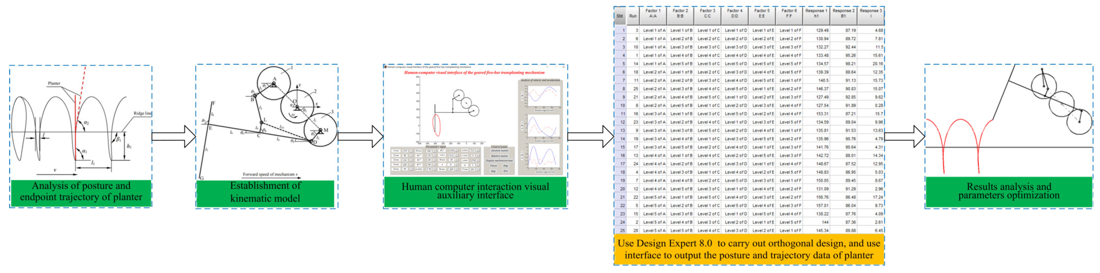
A flow chart of the optimization is shown in Figure 1. First, this section analyzes the posture and trajectory of the planter according to the agronomic requirements. Then, the human–computer interactive auxiliary interface is developed through the kinematics model of the transplanting mechanism. Finally, by taking the parameters of posture and trajectory for the planter obtained from the above analysis as the optimal objective, a group of optimal parameters is obtained by orthogonal design.
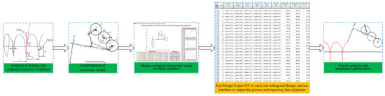
Figure 1.
Flow chart of optimization for geared five-bar transplanting mechanism.
3.1. Analysis of Posture and Endpoint Trajectory for Planter
In order to ensure the seedling rate of the mechanized planting of Salvia miltiorrhiza seedlings, the duck-billed planter of the transplanting mechanism planted the Salvia miltiorrhiza seedlings; this was necessary to ensure that the Salvia miltiorrhiza seedlings were perpendicular to the ridge surface when falling into the cavitation. In the process of withdrawing from the cavitation, it was important to try and keep the planter perpendicular to the ridge surface. After the planter exited the cavitation, the Salvia miltiorrhiza seedlings inclined slightly along the forward direction of operation velocity for the transplanting mechanism before separating from the planter completely. To prevent the Salvia miltiorrhiza seedlings from being pushed down by the planter, the angle between the Salvia miltiorrhiza seedlings and the ridge surface line was closer to 90°, as the included angle between the planter and ridge surface line should not be less than 80°.
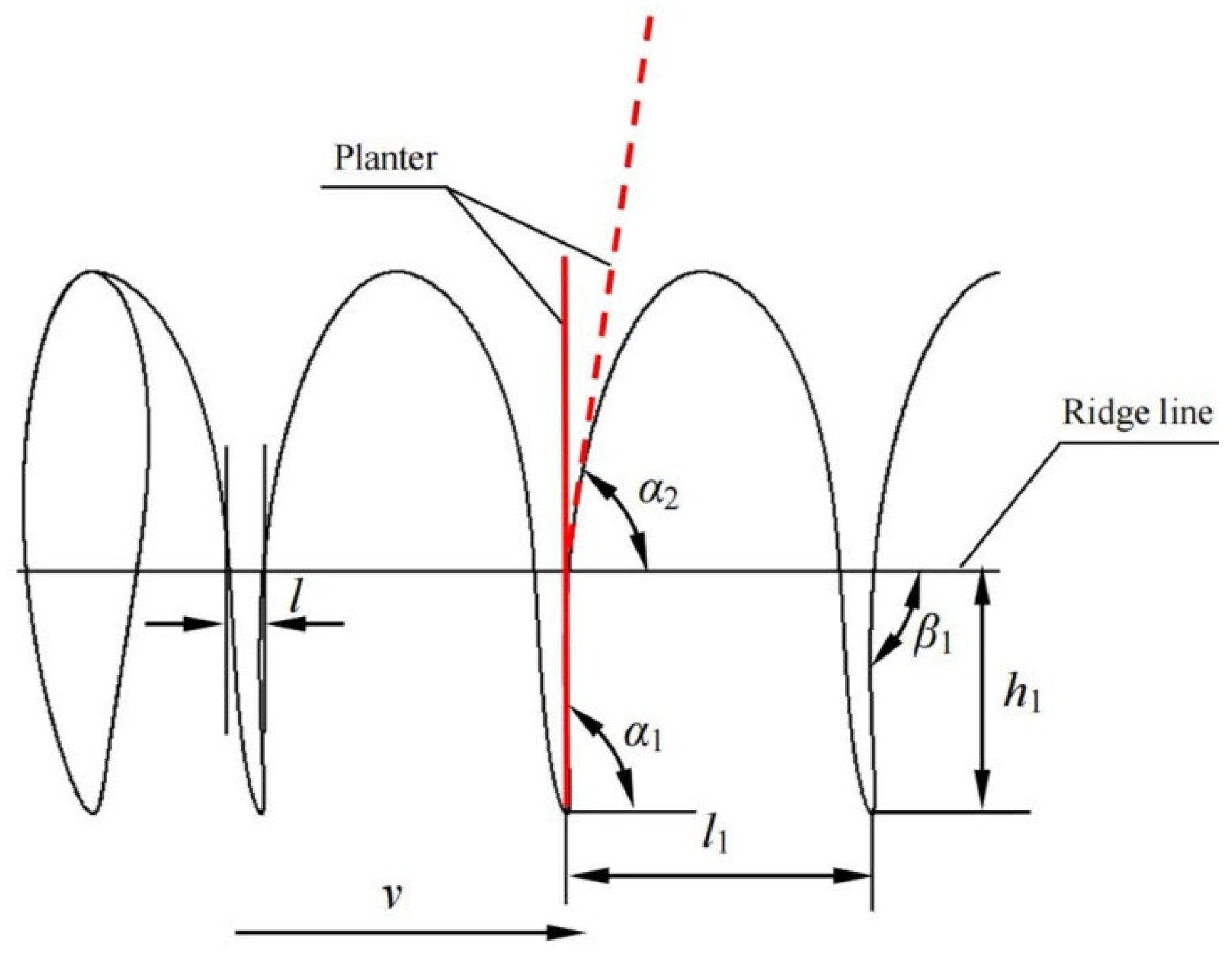
The relative and absolute trajectories of the endpoint for the planter are shown in Figure 2. The planting depth of the Salvia miltiorrhiza seedlings was 150 mm, and the planting space was 200 mm. In order to meet the agronomic requirements of the Salvia miltiorrhiza planting, the absolute trajectory met the following conditions: (1) the vertical distance h1 between the lowest point of the absolute trajectory and ridge surface line was 150 mm; (2) the included angle α1 between the planter and ridge surface line when the planter was at the lowest point of trajectory was not less than 80°; (3) the included angle α2 between the planter and ridge surface line when the planter started to withdraw from the ridge was not less than 80°; (4) the included angle β1 between the absolute trajectory and ridge surface line in the withdrawal process of the planter was not less than 80°; (5) the distance of the intersection l between the absolute trajectory and ridge surface line in a single motion cycle was as small as possible.
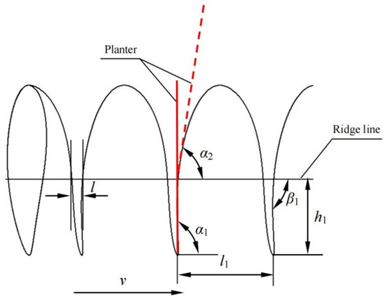
Figure 2.
Endpoint of trajectory analysis for planter. Notes: h1 represents the vertical distance between the lowest point of absolute trajectory and ridge surface; α1 represents the included angle between the planter and ridge surface line when the planter was at the lowest point of the trajectory; α2 represents the included angle between the planter and ridge surface line when the planter started to withdraw from the ridge; β1 represents the included angle between the absolute trajectory and ridge surface line in the withdrawing process of the planter; l represents the distance of intersection between the absolute trajectory and ridge surface line in a single motion cycle; v represents the forward velocity of the mechanism.
3.2. Working Principle and Model Establishment
3.2.1. Working Principle
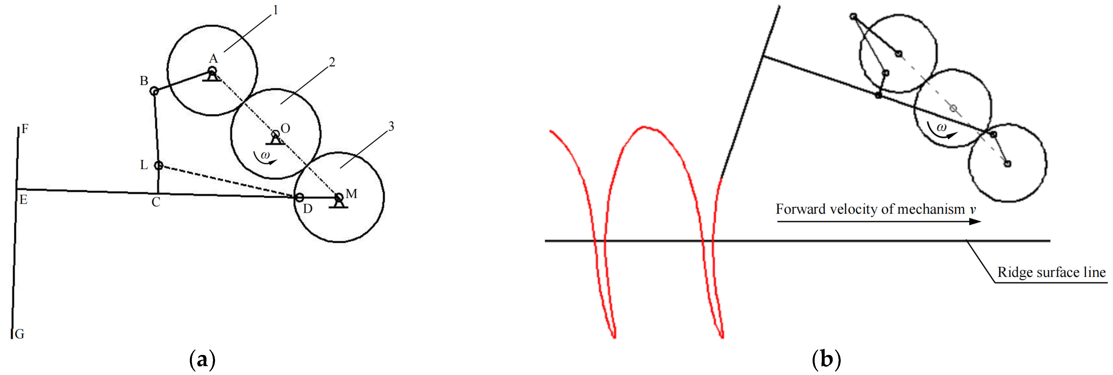
A structural diagram of the geared five-bar transplanting mechanism is shown in Figure 3a. The numbers 1, 2, and 3 refer to the spear gear, which comprised the straight cylindrical geared mechanism; AB and DM represent the double crank of the five-bar mechanism; BL and LD are the connecting rod of the five-bar mechanism; AM is the frame of the five-bar mechanism with spur gears; 1 and 3 in the geared mechanism being fixedly connected with the cranks AB and DM, respectively. The connecting rod DE was hinged with the crank DM, and FG was the planter fixedly connected with DE at a certain angle.
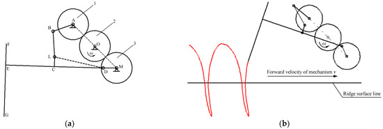
Figure 3.
Schematic diagram of transplanting mechanism: (a) Structural diagram; (b) Operation diagram.
During the operation, the power was transmitted from the spur gear at a constant angular velocity ω to drive spur gears 1 and 3 to rotate and to drive the cranks DM and AB to rotate in the same direction at the same velocity, and then to drive the connecting rods BL and DE to swing. The planter FG swung under the drive of DE, the mechanism moved forward at a constant velocity v, and, finally, the planter completed the planting operation under the combination of two movements, as shown in Figure 3b.
3.2.2. Model Establishment
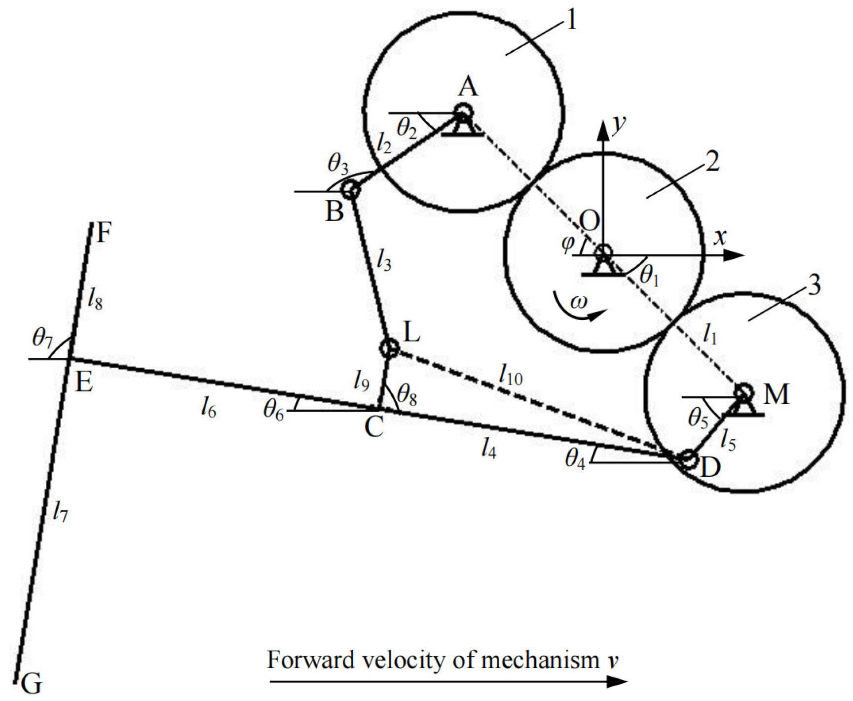
In this section, a rectangular coordinate system is established with point O as the coordinate origin, the horizontal direction as the x-axis, and the vertical direction as the y-axis, as shown in Figure 4. The parameters and meanings involved in the establishment of the model are shown in Table 1.
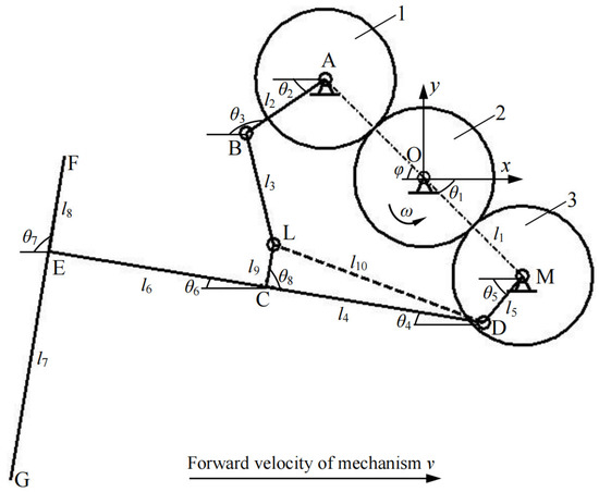
Figure 4.
Mathematical model of geared five-bar transplanting mechanism for Salvia miltiorrhiza. Notes: 1. cylindrical spur gear 1; 2. cylindrical spur gear 2; 3. cylindrical spur gear 1.

Table 1.
Explanation of related parameters.
The kinematic model of the mechanism was established as follows [29,30].
3.2.3. Displacement Equation
The displacement equation of point M,
The displacement equation of point A,
The displacement equation of point D,
The displacement equation of point B,
According to the vector equation ,
The displacement equation of point L,
Order,
Solving the Formula (5),
Replacing θ3 back into the Formula (6) to find θ4,
The displacement equation of point C,
The displacement equation of point E,
The displacement equation of point F,
The displacement equation of point G,
3.2.4. Velocity Equation
By deriving the displacement equation of point C, the velocity equation of point C was obtained,
Simplify Equation (11) to obtain the angular velocity of rod BC,
Replace Equation (12) to obtain the angular velocity of the DC rod,
By the derivation of the displacement equation at point E, the velocity equation of point E was obtained,
By the derivation of displacement equation at the point G, the velocity equation of point G was obtained,
3.2.5. Acceleration Equation
By the derivation of the C-point velocity equation to obtain the C point acceleration equation,
Order,
Calculation of the angular acceleration of DC rod and BC rod,
By the derivation of the E point velocity to obtain the E point acceleration equation,
By the derivation of the G point velocity to obtain the G point acceleration equation,
3.3. Human–Computer Interaction Visual Auxiliary Interface
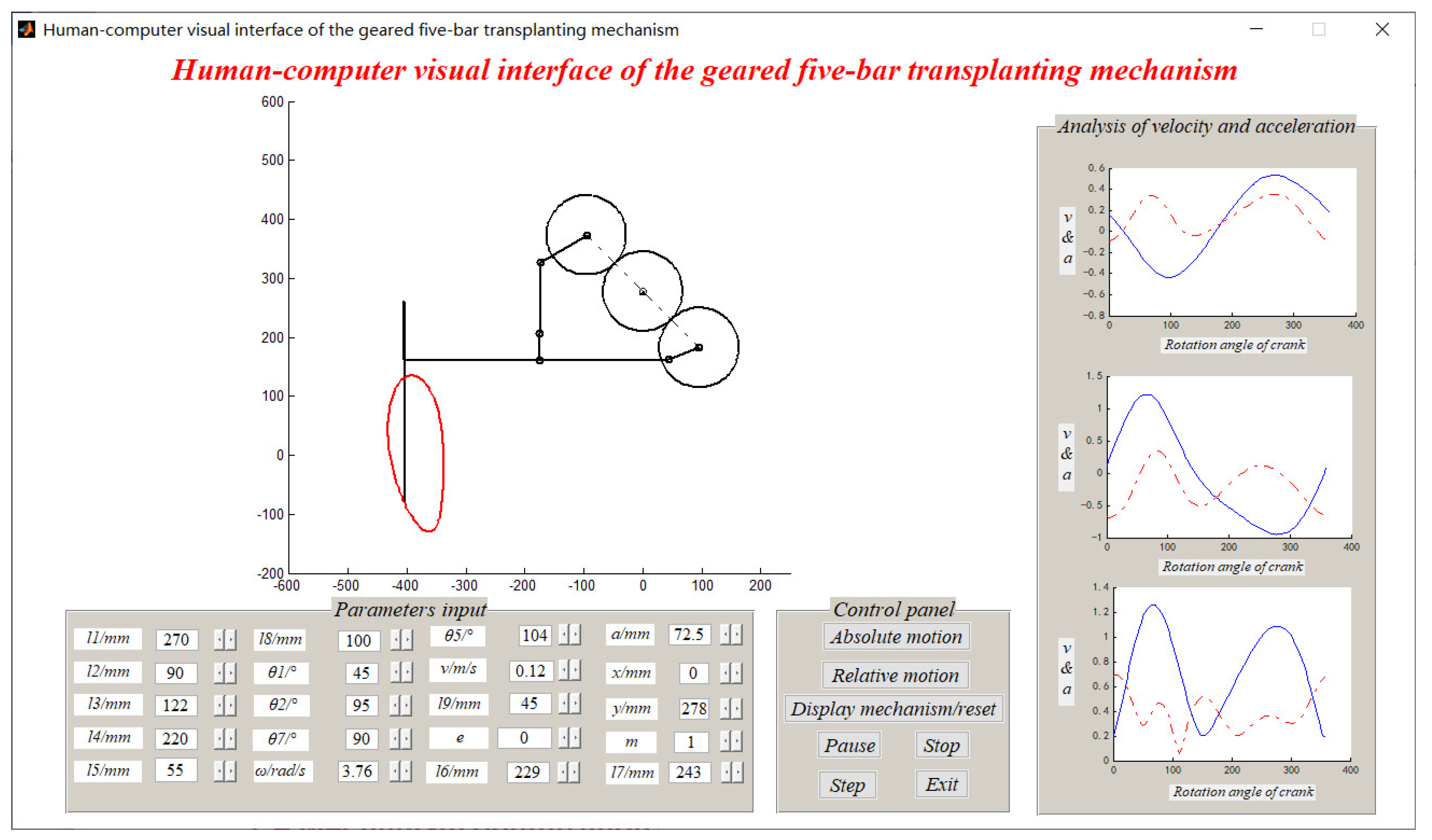
Based on the above mathematical model, this section uses MATLAB to compile the human–computer interaction visual auxiliary interface of the geared five-bar transplanting mechanism for Salvia miltiorrhiza (Software Copyright Registration Num., 2017sr663379), as shown in Figure 5.
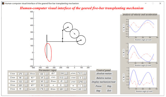
Figure 5.
Human–computer visual interface of the geared five-bar transplanting mechanism for Salvia miltiorrhiza.
3.4. Mechanism Optimization
Due to the large number of parameters on the geared five-bar transplanting mechanism for Salvia miltiorrhiza, this section takes the human–computer interaction visual auxiliary interface as the carrier, the key parameters of the mechanism as the factors, and the parameters of trajectory and inclined angle of the planter as the response indicators. Based on this, an orthogonal experimental design was carried out to obtain the optimal combination of parameters.
3.4.1. Determination of Factor Level
The selected factors were the various parameters of the five-bar transplanting mechanism that affected the absolute trajectory of mechanism. The main factors affecting the absolute trajectory of the five-bar transplanting mechanism were the length l2 of crank AB, the length l5 of crank MD, the difference between the installation angles θ5–θ2 of the double cranks, the length l3 of connecting rod BC, and the distance l10 between hinge points D and L. According to the value range of the constraint conditions, the level of the factors was determined to be five levels, and the test factor codes are shown in Table 2.
Table 2.
Experimental variables and levels.
3.4.2. Determination of Response Indicators
In terms of the constraint conditions obtained from the analysis of the posture and trajectory of the planter, the response index was determined as the vertical distance h1 between the lowest point of absolute trajectory and the ridge surface line, the included angle α1 between the planter and ridge surface line when the planter was at the lowest point of trajectory, the included angle α2 between the planter and ridge surface line when the planter started to withdraw from the ridge, the included angle β1 between the absolute trajectory and ridge surface line in the withdrawal process of the planter, and the distance of intersection l between the absolute trajectory and ridge surface line in a single motion cycle.
3.4.3. Method and Result Analysis
This section uses the five-factor and five-level orthogonal test L25 (56) method, utilizing Design-Expert 6.0 software for the orthogonal design, combined with the auxiliary interface simulation results. The scheme and results are shown in Table 3.
Table 3.
Orthogonal design layout and results.
As shown in Table 3, for h1, the factors affecting the order of priority is A > D > B > E > C. For β1, the factors affecting the order of priority is A > B > C > E > D. For l, the factors affecting the order of priority is C > D > B > A > E. For α1, the factors affecting the order of priority is A > D > C > E > B. For α2, the factors affecting the order of priority is A > B > D > E > C.
4. Results and Discussion
4.1. Results Analysis
4.1.1. Determination of Optimal Result
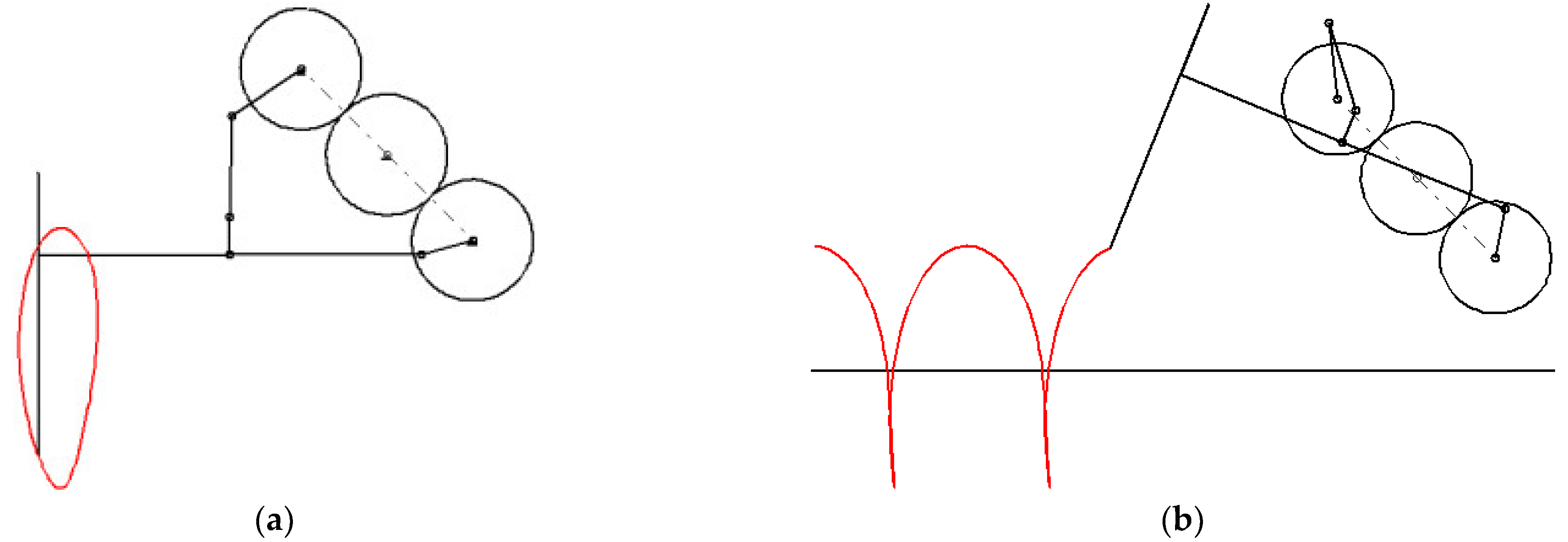
According to the analysis of the posture and trajectory for the planter, the optimal target of the response index was obtained, with the 19th A4B4C2D5E3 in Table 3 being the optimal parameter combination. Through the auxiliary interface, the relative and absolute trajectories under the optimal parameters were output, as shown in Figure 6. The parameter combination was l1 = 290 mm, l2 = 100 mm, l3 = 124 mm, l4 = 231 mm, l5 = 64 mm, l6 = 229 mm, l7 = 243 mm, l8 = 100 mm, l9 = 45 mm, θ1 = 45°, θ5–θ2 = 19°, θ7 = 90°, and θ8 = 90°. Meanwhile, the corresponding absolute trajectory parameter was h1 = 150.1 mm, β1 = 89.5°, l = 8.7 mm, α1 = 90.5°, and α2 = 82.5°.
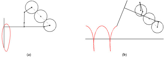
Figure 6.
Trajectory of endpoint for planter under the optimal parameters: (a) Relative trajectory for planter under the optimal parameters; (b) Absolute trajectory for planter under the optimal parameters.
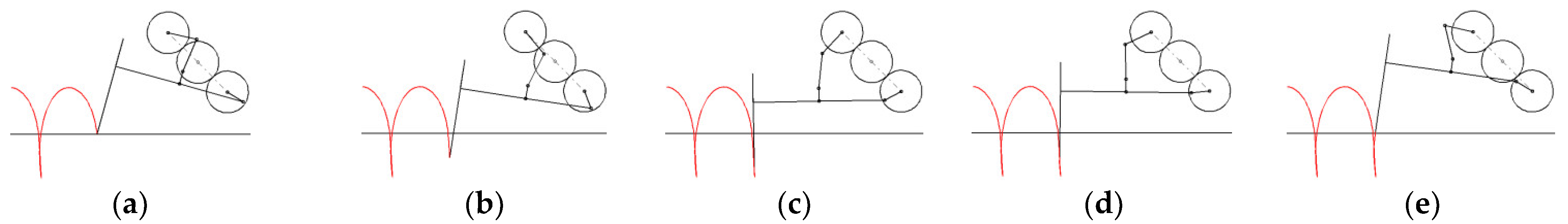
The posture of the planter in the process for planting Salvia miltiorrhiza seedlings is shown in Figure 7.
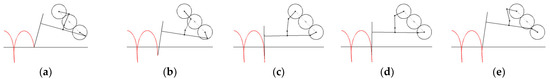
Figure 7.
Posture of planter in the process of planting: (a) Just entered the ridge; (b) Insert the ridge; (c) Start planting; (d) During planting; (e) Planting is over.
4.1.2. Comparing Results before and after Optimization
The optimal parameters of the absolute trajectory and posture of the planter were compared to the corresponding parameters in the literature [19], as shown in Table 4. The optimized h1, β1, and α2 basically remained unchanged. The optimized α1 increased approximately 1.9° compared to that before optimization. The optimized l reduced approximately 13.6 mm compared to that before optimization, which means that the length of the hole formed by the transplanting mechanism was reduced by 13.6 mm.
Table 4.
Parameter comparison of absolute trajectory and posture for planter before and after optimization.
4.2. Mechanism Development
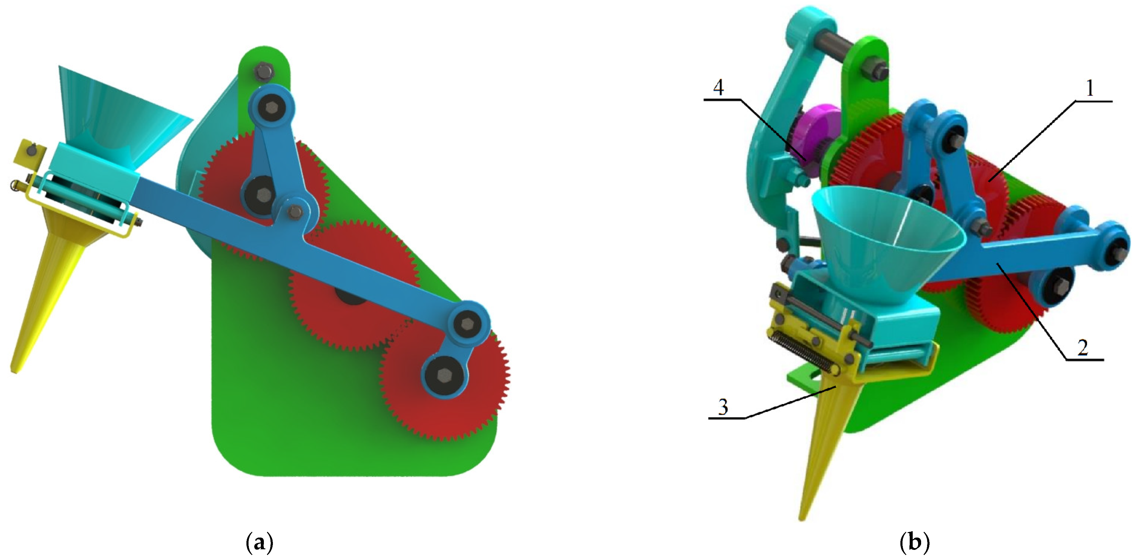
A three-dimensional model of the geared five-bar transplanting mechanism for Salvia miltiorrhiza is shown in Figure 8. It consists of a double-crank five-bar mechanism, a duck-billed planter, a cam-pull arm opening and closing control mechanism, and a geared transmission mechanism. The double-crank five-bar mechanism controls the duck-billed planter to make a reciprocating motion for seedling grafting and planting. The duck-billed planter is an end-effector for planting, which forms the cavitation and plants the Salvia miltiorrhiza seedlings into the cavitation. The cam-pull arm opening and closing control mechanism controls the rotation of the crank to drive the cam to rotate and realize the reciprocating motion of the pull arm, and then, it drives the pull wire to open and close the duck-billed planter to ensure that the Salvia miltiorrhiza seedlings enter the ridge from the planter. The geared transmission mechanism transmits the power to the double cranks of the five-bar mechanism.
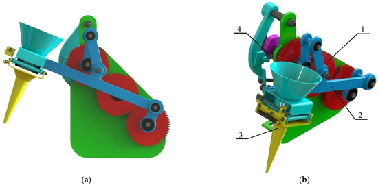
Figure 8.
Structural design of geared five-bar transplanting mechanism for Salvia miltiorrhiza: (a) Front view of geared five-bar transplanting mechanism; (b) Axonometric view of geared five-bar transplanting mechanism. Notes: 1. Geared transmission mechanism; 2. Double-crank five-bar mechanism; 3. Duck-billed planter; 4. Cam-pull arm opening and closing control mechanism.
4.3. Bench Test
The bench test was used to measure the actual trajectory formed by the endpoint of the planter to verify the accuracy of the mechanism optimization [31,32].
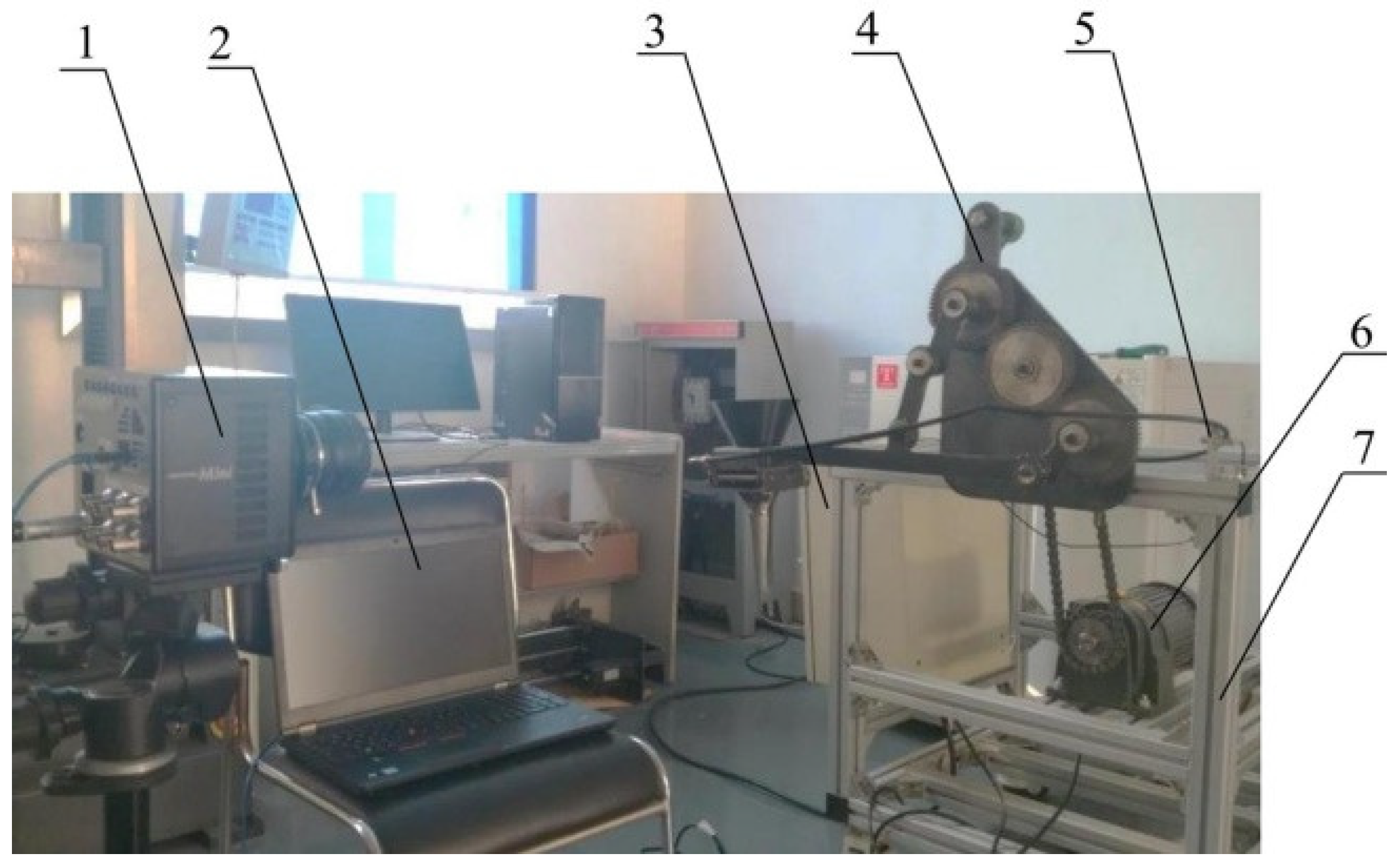
The prototype and test platform are shown in Figure 9. The test platform was composed of the geared five-bar transplanting mechanism for Salvia miltiorrhiza, YSJ750 speed-regulating motor, JAC580N frequency converter, SJM12-10P1 hall effect tachometric transducer, 160K-C-8GB high-speed camera, and the other equipment.
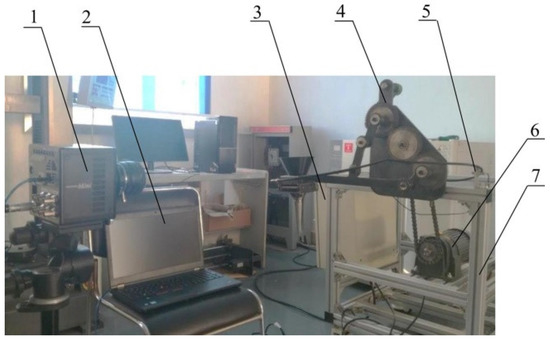
Figure 9.
Overall layout of the test platform. Notes: 1. High-speed camera; 2. Computer; 3. Frequency conversion cabinet; 4. Transplanting mechanism; 5. Hall effect tachometric transducer; 6. Speed regulating motor; 7. Frame.
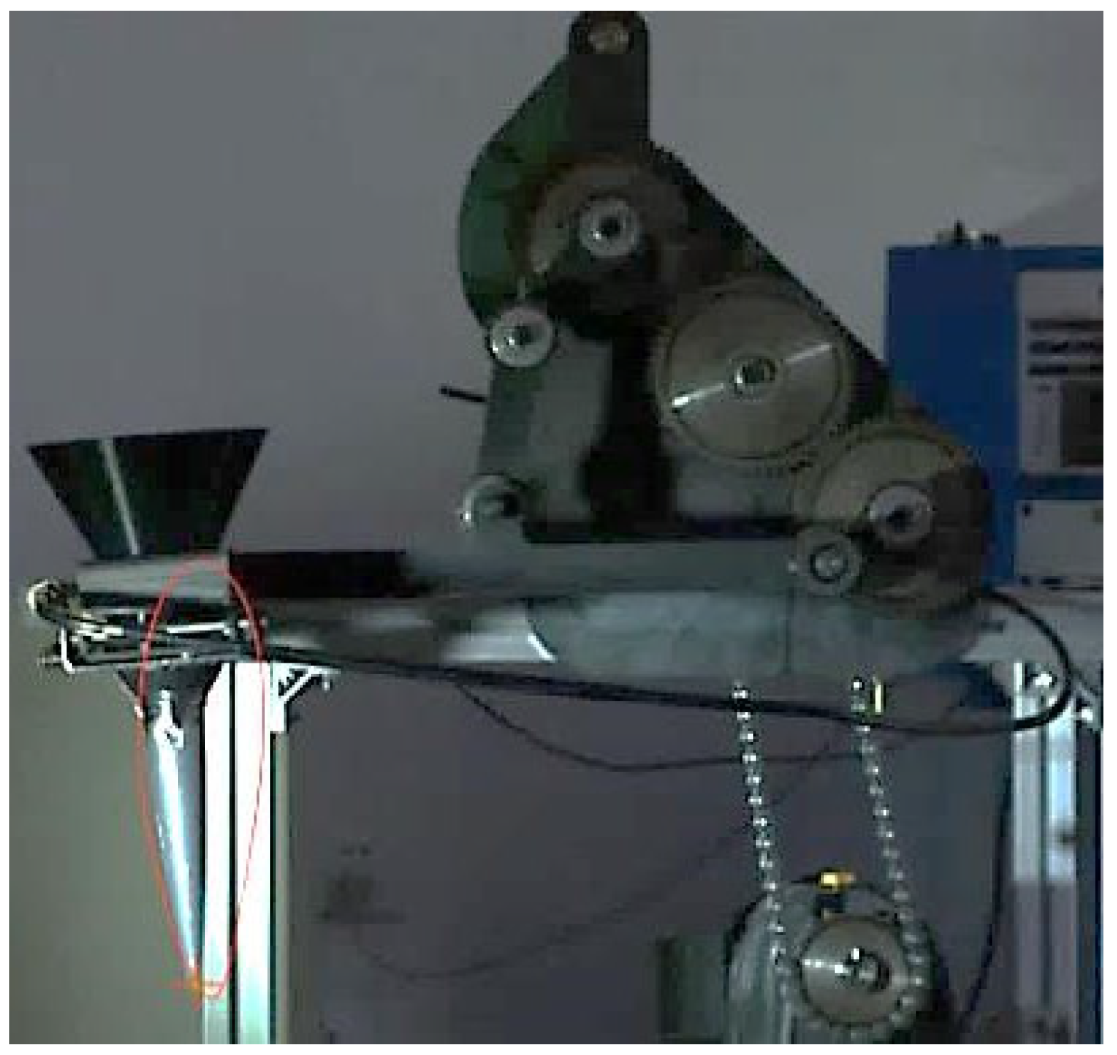
The actual trajectory of the geared five-bar transplanting mechanism for Salvia miltiorrhiza was measured by a high-speed camera for comparison with the simulation of the interface. The actual trajectory of the mechanism obtained by the high-speed camera system is shown in Figure 10. The theoretical trajectory in Figure 5a was basically the same as the actual trajectory, thus verifying the accuracy of the mechanism optimization.
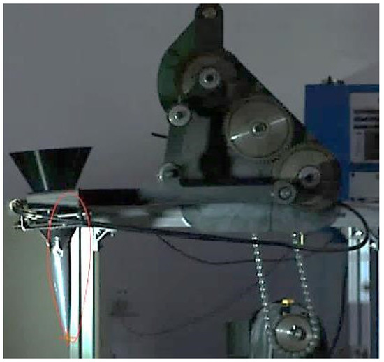
Figure 10.
Actual measurement of relative motion for transplanting mechanism.
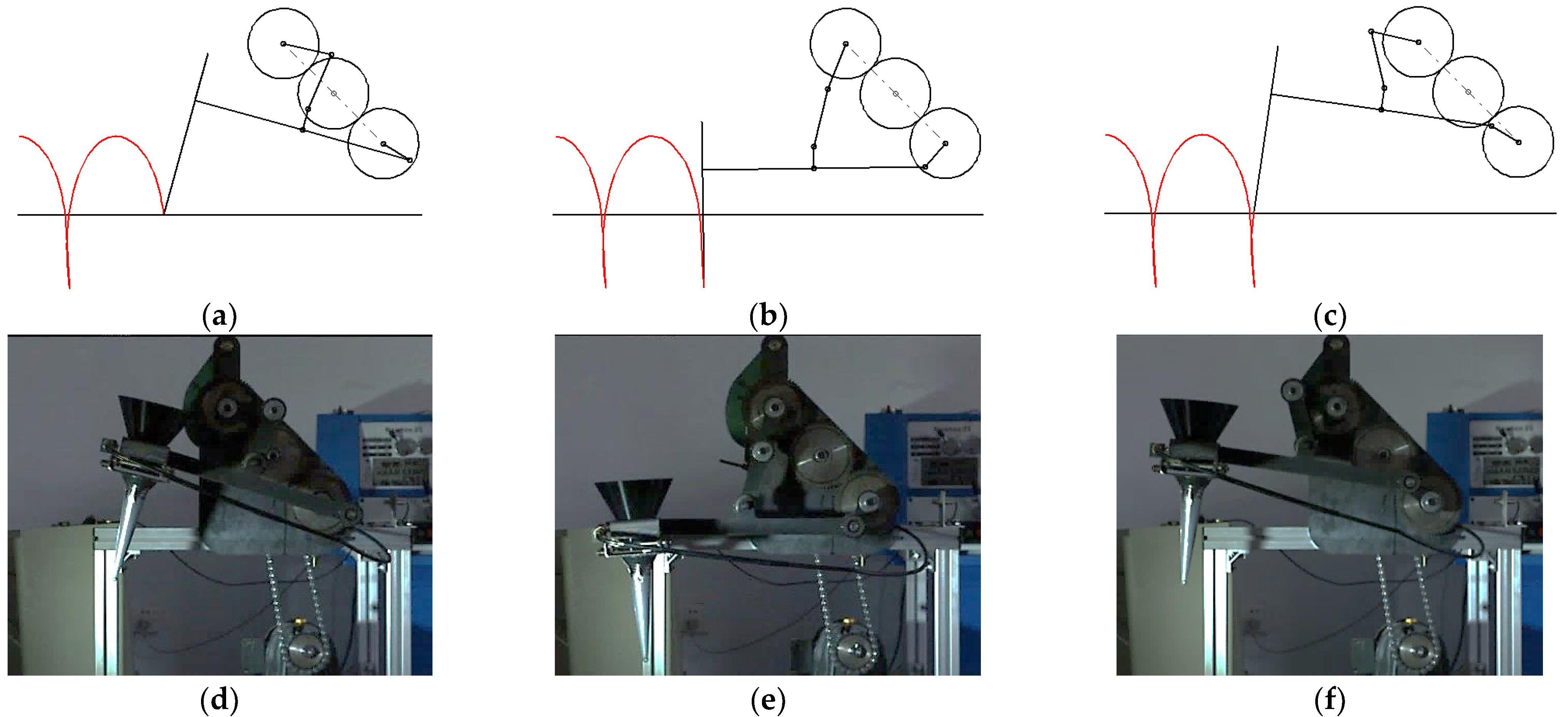
A comparison between the theoretical and actual postures of the planter for the mechanism is shown in Figure 11. The results show that the theoretical posture of the planter was basically the same as the actual posture of the planter, thus verifying the accuracy of the mechanism optimization.
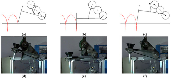
Figure 11.
Comparison of theoretical and actual posture of transplanting mechanism for Salvia miltiorrhiza: (a) Theoretical posture of intruding; (b) Theoretical posture of planting; (c) Theoretical posture of withdrawing; (d) Actual posture of intruding; (e) Actual posture of planting; (f) Actual posture of withdrawing.
5. Conclusions
- (1)
- On the basis of analyzing the structural composition and working principle for the transplanting mechanism, the human–computer interactive auxiliary interface was established through the kinematics model.
- (2)
- With the aid of the auxiliary interface and orthogonal design, the combination of parameters that improve the operation performance and quality of the geared five-bar transplanting mechanism for Salvia miltiorrhiza were obtained (l1 = 290 mm, l2 = 100 mm, l3 = 124 mm, l4 = 231 mm, l5 = 64 mm, l6 = 229 mm, l7 = 243 mm, l8 = 100 mm, l9 = 45 mm, θ1 = 45°, θ5–θ2 = 19°, θ7 = 90°, and θ8 = 90°). Compared to before optimization, the optimized h1, β1, and α2 were basically unchanged. The optimized α1 increased approximately 1.9°, while the optimized l reduced by approximately 13.6 mm, which means that the length of the hole formed by the transplanting mechanism was reduced by 13.6 mm.
- (3)
- According to the optimal combination of parameters, a test bench system of the transplanting mechanism was built. The actual trajectory of the transplanting mechanism prototype was obtained by using high-speed photography technology. The bench test results showed that the comparison between the actual measurements and the theoretical analysis results was basically consistent, thus verifying the accuracy of the mechanism optimization.
In this study, the optimal parameters of the transplanting mechanism were obtained through orthogonal design combined with the human–computer interaction interface, providing a new method of parameter optimization for the transplanting mechanism. The method did not analyze the influence of the parameters for the mechanism on the posture and trajectory of the planter. The actual cavitation-forming operation of the transplanting mechanism was realized by the interaction between the planter and soil, and the research on the cavitating law of the transplanting mechanism and soil will be the focus in the future.
Author Contributions
Conceptualization, G.X. and H.F.; Data curation, G.X. and Y.S.; Formal analysis, W.D.; Investigation, G.X. and Y.S.; Methodology, H.F. and Y.S.; Project administration, H.F.; Resources, G.X. and H.F.; Software, G.X. and N.W.; Supervision, G.X. and N.W.; Validation, G.X., H.F. and N.W.; Visualization, G.X. and W.D.; Writing—original draft, G.X. and H.F.; Writing—review and editing, Y.S. and W.D. All authors have read and agreed to the published version of the manuscript.
Funding
This research was supported by the National College Students Innovation and Entrepreneurship Training (202211510017), the Doctoral Scientific Research Foundation of Shandong Jiaotong University (BS2020002), and the Scientific Research Foundation of Shandong Jiaotong University (Z2020008).
Institutional Review Board Statement
Not applicable.
Informed Consent Statement
Not applicable.
Data Availability Statement
The data presented in this study are available on demand from the first author at (202107@sdjtu.edu.cn).
Conflicts of Interest
The authors declare no conflict of interest.
References
- Tian, Y.; Song, J.; Lai, M.; Song, Z. Influence of fertigation integrated cultivation of Salvia miltiorrhiza on weed biomass. Shandong Agric. Sci. 2020, 52, 96–99. [Google Scholar]
- Lei, L.; Guo, Q.; Wang, C.; Ma, Z.; Cao, Y.; An, J. Effects of compound planting on growth and quality of Salvia miltiorrhiza. China J. Chin. Mater. Med. 2018, 43, 1818–1824. [Google Scholar]
- Chen, X.; He, C.; Yan, B.; Li, W.; Geng, Y.; Hou, J.; Wang, W. Investigation and analysis on difference of cultivation technique situation of Salvia miltiorrhiza. China J. Chin. Mater. Med. 2019, 44, 1314–1320. [Google Scholar]
- Wang, K.; Chao, J.; Gu, W.; Sheng, Y.; Su, S.; Xia, Y.; Wang, Y.; Hui, X.; Wang, Y. Effects of different seedling raising methods on the morphology, agronomic characters and physiological and biochemical indexes of Salvia miltiorrhiza Bunge seedlings. J. South. Agric. 2020, 51, 162–168. [Google Scholar]
- Jiang, L.; Tian, C.; Li, J.; Sun, J. Standardized and industrialized planting technology of Salvia miltiorrhiza. J. Zhejiang Agric. Sci. 2019, 60, 1842–1845+1849. [Google Scholar]
- Zhao, Y.; Fan, F.; Song, Z.; Na, M.; Zuo, Y.; Feng, Y.; Ji, H. Design and simulation of inverted vegetable pot seedling transplanting mechanism with conjugate cam. Trans. Chin. Soc. Agric. Eng. 2014, 30, 8–16. [Google Scholar]
- Hwang, S.; Park, J.; Lee, J.; Shim, S.; Nam, J. Optimization of Main Link Lengths of Transplanting Device of Semi-Automatic Vegetable Transplanter. Agronomy 2020, 10, 1938. [Google Scholar] [CrossRef]
- Cui, Z.; Guan, C.; Xu, T.; Fu, J.; Chen, Y.; Yang, Y.; Gao, Q. Design and experiment of transplanting machine for cabbage substrate block seedlings. INMATEH Agric. Eng. 2021, 64, 375–384. [Google Scholar] [CrossRef]
- Xu, G.; Jian, S.; Song, Y.; Fang, H.; Qiu, X.; Ming, X. Design and Experiment of Cellar Cavitation Mechanism for Crops of Hilly Mountains Transplanter. Trans. Chin. Soc. Agric. Mach. 2022, 53, 105–113+125. [Google Scholar]
- Cui, W.; Liu, S.; Gao, L.; Wang, R.; Wang, J. Development of 2ZFS-1A multifunctional tobacco transplanting machine. Trans. Chin. Soc. Agric. Eng. 2012, 28, 36–41. [Google Scholar]
- Xie, Q.; Liu, F.; Yang, M.; Liu, J.; Yang, S.; Xie, S. DEM simulation and evaluation of well cellar making performance. INMATEH Agric. Eng. 2021, 63, 41–50. [Google Scholar] [CrossRef]
- Wu, J.; Yu, W.; Zhang, M.; Wu, C.; Jiang, L.; Tang, Q. Design and experiment of 2ZY-6 rapeseed blanket seedling transplanting machine. Trans. Chin. Soc. Agric. Mach. 2020, 51, 95–102+275. [Google Scholar]
- Sri, M.; Hwang, S.; Nam, J. Experimental safety analysis of transplanting device of the cam-type semi-automatic vegetable transplanter. J. Terramechanics 2022, 103, 19–32. [Google Scholar] [CrossRef]
- Iqbal, M.; Islam, M.; Ali, M.; Kiraga, S.; Kim, Y.; Chung, S. Theoretical overturning analysis of a 2.6-kW two-Row walking-type automatic pepper transplanter. J. Biosyst. Eng. 2022, 47, 79–91. [Google Scholar] [CrossRef]
- Reza, M.; Islam, M.; Chowdhury, M.; Ali, M.; Islam, S.; Kiraga, S.; Lim, S.; Choi, L.; Chung, S. Kinematic analysis of a gear-Driven rotary planting mechanism for a six-row self-propelled onion transplanter. Machines 2021, 9, 183. [Google Scholar] [CrossRef]
- Wang, K.; Gu, Y.; Sheng, Y.; Shen, X.; Han, Y.; Su, S.; Wang, Y.; Hui, X.; Gu, W.; Chao, J. Screening and optimization of nutrient solution for soilless seedling raising of Salvia miltiorrhiza. Soil Fertil. Sci. China 2020, 5, 243–249. [Google Scholar]
- Stubbs, S.; Colton, J. The Design of a Mechanized Onion Transplanter for Bangladesh with Functional Testing. Agriculture 2022, 12, 1790. [Google Scholar] [CrossRef]
- Liu, M.; Hu, X.; Liao, Y.; Liao, Y.; Wan, X.; Yi, M. Morphological parameters characteristics of mechanically transplanted plant in suitable transplanting period for different rape varieties. Trans. Chin. Soc. Agric. Eng. 2015, 31, 243–249. [Google Scholar]
- Xu, G.; Liu, H.; Jian, S.; Shi, S.; He, T. Design and Test of Transplanting Mechanism on Mulch-film of Salvia miltiorrhiza Based on Five-bar Mechanism. Trans. Chin. Soc. Agric. Mach. 2018, 49, 55–65. [Google Scholar]
- Yu, G.; Tong, Z.; Sun, L.; Tong, J.; Zhao, X. Novel gear transmission mechanism with twice unequal amplitude transmission Ratio. J. Mech. Des. 2019, 141, 092304. [Google Scholar] [CrossRef]
- Hu, J.; Pan, J.; Zhang, C.; Zhang, S.; Fei, W.; Pan, H. Optimization design and experiment on planetary gears planting mechanism of self-propelled transplanting machine. Trans. Chin. Soc. Agric. Mach. 2018, 49, 78–86. [Google Scholar]
- Wang, Y.; Chen, J.; Zhao, X.; Sun, X. Parameter optimization and experiment of planting mechanism driven by plantary non-circular gears. Trans. Chin. Soc. Agric. Mach. 2015, 46, 85–93. [Google Scholar]
- Zhou, H.; Yang, W.; Yu, G.; Wang, B.; Ye, B. Optimization design and experiments of ditching multi-bar seedling planting mechanism. Trans. Chin. Soc. Agric. Mach. 2023, 1–10. Available online: http://kns.cnki.net/kcms/detail/11.1964.S.20230112.0909.003.html (accessed on 16 January 2023).
- Wu, G.; Yu, G.; Ye, B.; Yu, Y. Forward-reverse design method for rice potted-seedling transplanting mechanism with compound planetary gear train. Trans. Chin. Soc. Agric. Mach. 2020, 51, 85–93+102. [Google Scholar]
- Sun, L.; Shen, J.; Zhou, Y.; Ye, Z.; Yu, G.; Wu, C. Design of non-circular gear linkage combination driving type vegetable pot seedling transplanting mechanism. Trans. Trans. Chin. Soc. Agric. Mach. 2019, 35, 26–33. [Google Scholar]
- Chen, J.; Huang, Q.; Wang, Y.; Sun, L.; Zhao, X.; Wu, C. Parametric analysis and inversion of transplanting mechanism with planetary non-circular gears for potted-seedling transplanter. Trans. Chin. Soc. Agric. Eng. 2013, 29, 18–26. [Google Scholar]
- Liao, Q.; Liu, M.; Zhang, Z.; Hu, X. Multi-objective optimization design of double five-bar transplanting mechanism for rape pot seedling. Trans. Chin. Soc. Agric. Mach. 2015, 46, 49–56. [Google Scholar]
- Zhu, W.; Zhang, C.; Pang, Q. Design and Optimization of the Crawling Mechanism of Rotary Sidewall Coring Device in Shale Gas Wells. Pet. Drill. Tech. 2021, 49, 100–104. [Google Scholar]
- Zhao, X.; Guo, J.; Li, K.; Dai, L.; Chen, J. Optimal design and experiment of 2-DoF five-bar mechanism for flower seedling transplanting. Comput. Electron. Agric. 2020, 178, 105746. [Google Scholar] [CrossRef]
- Chen, J.; Huang, Q.; Wang, Y.; Zhang, G. Kinematics modeling and analysis of transplanting mechanism with planetary elliptic gears for pot seedling transplanter. Trans. Chin. Soc. Agric. Eng. 2012, 28, 6–12. [Google Scholar]
- Ye, B.; Zeng, G.; Deng, B.; Yang, Q.; Liu, J.; Yu, G. Design and tests of a rotary plug seedling pick-up mechanism for vegetable automatic transplanter. Int. J. Agric. Biol. Eng. 2020, 13, 70–78. [Google Scholar] [CrossRef]
- Hu, S.; Hu, M.; Yan, W.; Zhang, W. Design and experiment of an integrated automatic transplanting mechanism for picking and planting pepper hole tray seedlings. Agriculture 2022, 12, 557. [Google Scholar] [CrossRef]
Disclaimer/Publisher’s Note: The statements, opinions and data contained in all publications are solely those of the individual author(s) and contributor(s) and not of MDPI and/or the editor(s). MDPI and/or the editor(s) disclaim responsibility for any injury to people or property resulting from any ideas, methods, instructions or products referred to in the content. |
© 2023 by the authors. Licensee MDPI, Basel, Switzerland. This article is an open access article distributed under the terms and conditions of the Creative Commons Attribution (CC BY) license (https://creativecommons.org/licenses/by/4.0/).