Communication

Influences of Flow Channel on Electrochemical Characteristics of Polymer Electrolyte Fuel Cells Humidified with NaCl Contained H2O

Department of Mechanical Engineering, Dankook University, 152 Jukjeon-ro, Suji-gu, Yongin-si 16890, Gyeonggi-do, Republic of Korea
*
Author to whom correspondence should be addressed.
Sustainability 2023, 15(3), 2415; https://doi.org/10.3390/su15032415
Submission received: 31 December 2022 / Revised: 12 January 2023 / Accepted: 18 January 2023 / Published: 29 January 2023
(This article belongs to the Topic Advanced Engines Technologies)

Abstract

:
In this study, the effects of flow field types on the electrochemical properties of polymer electrolyte membrane fuel cells (PEMFCs) humidified with NaCl solution are systematically investigated. The parallel flow field and serpentine flow field were used to investigate the PEMFCs. Long-term stability was evaluated for 20 h using chronoamperometry. Fuel cells with both parallel and serpentine flow fields showed a decrease in performance because of the NaCl solution. Interestingly, the PEMFC with the serpentine flow field showed significantly more severe degradation during long-term stability evaluation compared to the fuel cell with the parallel flow field. Electrochemical impedance spectroscopy analysis showed that a significant increase in faradaic resistance caused the degradation of the performance. After long-term stability examinations, regenerations of fuel cells were performed with deionized water at a constant voltage (0.4 V). After the regeneration, the performance of the fuel cells with the serpentine flow field was improved more (52.96%) than the PEMFC with the parallel flow field (1.22%).

1. Introduction

Fuel cells are known as one of the most efficient energy conversion devices since they directly convert the chemical energy of fuel into electrical energy [1]. Among various types of fuel cells, polymer electrolyte membrane fuel cells (PEMFCs) are commercialized due to their high energy density, fast start-up/shut-down, and low operating temperature (<100 °C) [1,2,3,4]. PEMFCs are widely adopted as the primary power sources of fuel cell electric vehicles, ships, and drones because of their strong points, especially the low operation temperature [5,6,7,8,9].
Fuel cells are composed of many components [1,10,11]. Among the components, bi-polar plates have a unique flow field. The flow field of the bipolar plate is a passage for the proper distribution of fuel, air, and H2O [1,12,13]. Furthermore, the flow field serves to remove products of electrochemical reactions (H2O) produced through electrochemical reactions at the triple phase boundaries (TPBs) of fuel cells [14,15,16]. Therefore, the design of the flow field is considered one of the most crucial factors for the improvement of the performance and durability of fuel cells [17,18,19]. Among various flow field patterns, the most commonly used types are the serpentine flow field and the parallel flow field [20]. The single-channel serpentine flow field can effectively remove products based on a high-pressure difference between the gas inlet and the outlet [21,22]. However, the parallel flow field can distribute concentrations of materials more evenly compared to other types of flow fields [1,23,24]. In addition, the design of the flow field should consider the appropriate H2O distribution inside the fuel cell. In general, H2O is supplied to fuel cells by the humidification of gases and generation by electrochemical reactions [1]. Externally supplied water is significantly crucial for the performance of the Nafion® electrolytes [1]. Hydrogen ions (H+) move through the ionomer, from the anode to the cathode, with water [1,25]. The transfer of the H2O to the ionomer effectively increases proton conductivity and current density. However, when excess H2O is supplied in the aerosol state, it easily changes to the droplet state in the fuel cell [26]. The droplets, i.e., liquid H2O, interrupt the gas supply through the gas diffusion layer (GDL) and the catalyst layer (CL) [27,28]. Therefore, the performance of fuel cells is due to a restricted supply of reactants and the removal of products. However, the ion conductivity and durability of the electrolytes decrease when moisture is insufficient, i.e., the ionomer dries [29]. Thus, appropriate humidification is critical for the polymer electrolyte membrane fuel cells.
As we mentioned above, the flow field is significantly important for the electrochemical properties of fuel cells. Additionally, the effects of the flow field related to the material distribution are substantially more important for the fuel cell used in marine environments due to the inherent impurities of seawater. When air is supplied to the fuel cell stack in marine environments, the NaCl solution in the air can be supplied. In addition, there are some reports that NaCl exists as a solution in the marine environment [30]. Na and Cl, which are one of the most abundant materials in seawater, are reported to be the main causes of performance degradation in PEMFCs [31]. Mikkola et al. reported that the proton conductivity of electrolytes decreased because Na+ is transported in place of H+ in the ionomers [32]. In addition, TPBs are reduced at the electrode of PEMFCs because of the absorption of Cl- on the Pt catalysts [33]. In addition, Cl affects PEMFC components such as the GDL and the separator [34]. L. Veleva et al. revealed that the cause of corrosion in copper specimens exposed to the marine environment was Cl [35]. In summary, impurities, including NaCl in seawater, can degrade the electrochemical properties of PEMFCs. In more detail, the supplied seawater mist, i.e., NaCl solution, moves through the flow field and then affects the electrochemical properties of fuel cells.
However, there are no systematic studies on the effects of the flow field on the electrochemical characteristics of fuel cells humidified with NaCl solution to the best of the author’s knowledge. Therefore, the effects of the flow field on the electrochemical characterization of PEMFCs humidified with NaCl solutions were systematically investigated. The performance and electrochemical impedance spectroscopy (EIS) of the fuel cells were measured. In addition, the long-term stability of the fuel cells was assessed for 20 h between 0.3 and 0.7 V. After the end of the long-term durability evaluation, a study on the regeneration of PEMFCs was conducted using deionized (DI) water.

2. Experiments

Figure 1 illustrates the piping and instrumentation drawing of the experimental setup. In this study, a custom-made mist generator was prepared using an ultrasonic vibrator. A mist of 3.5 wt.% NaCl solution was supplied using air blown by a mist generator. As shown in Figure 1, the mist generator was located between the fuel cell and the mass flow controller (MFC). The concentration of the NaCl solution was maintained at 3.5 wt.%, which is the average concentration of seawater. Then, 150 sccm of dry H2 (Samjung energy, Paju-si, Republic of Korea) was supplied to the anode side of the fuel cells, and 600 sccm of humidified air (Samjung energy, Paju-si, Republic of Korea) was supplied to the cathode of the fuel cells. The humidification of NaCl solution was conducted using a custom-made mist generator. The regeneration was carried out using a bubbler with DI water.
Commercial membrane electrode assemblies (MEAs) were used (CNL MEA C Type, CNL Energy, Seoul, Republic of Korea). The Pt loading of the MEA was 0.4 mg/cm2 for both the anode and cathode, and the total active area was 5.06 cm2. Additionally, the GDL was used (SGL, GDL 39 BB, Germany). Two graphite bipolar plates with a serpentine-type flow field and a parallel-type flow field were employed. The flow path had a depth of 0.8 mm and a width of 1.0 mm.
An electrochemical property analysis of PEMFCs was conducted using a commercial potentiostat (HCP-803, BioLogic, Seyssinet-Pariset, France) to measure the current density (j)–voltage (V)–power density (P) curves, EIS, chronoamperometry, and constant voltage mode (CV-mode). The EIS was measured at 0.5 V from the 0.2 MHz to 0.01 Hz frequency range. Chronoamperometry mode periodically measured the current of the fuel cells at 0.7 and 0.3 V for 20 h to evaluate the long-term stability of the fuel cells. After the long-term durability test with the custom-made mist generator, regeneration experiments were conducted using a bubbler with DI water. For the regeneration experiment, the current of fuel cells was measured with CV-mode at 0.4 V for 5 h. All experiments were conducted at 25 °C.

3. Results and Discussion

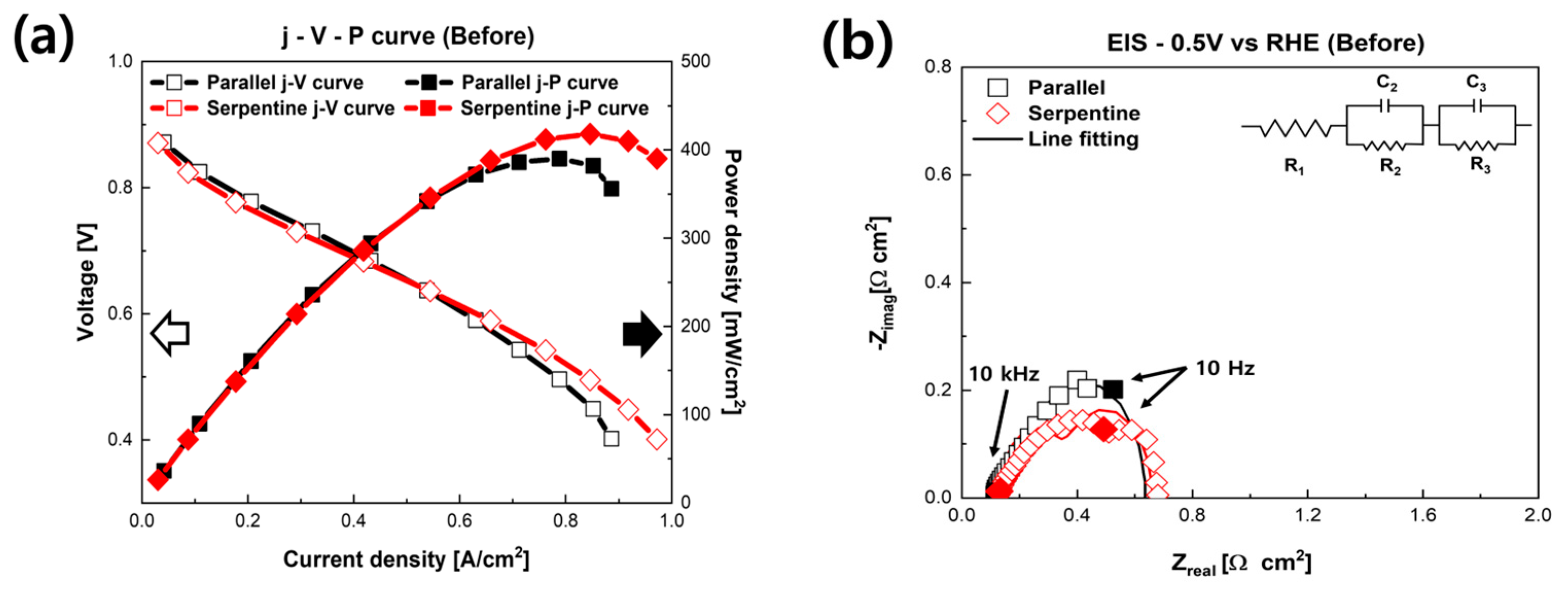
Figure 2 presents the polarization curves of fuel cells humidified with NaCl solution with different flow fields. Figure 2a shows the initial performance of PEMFCs humidified with NaCl solution. As shown in Figure 2a, the initial performances of the fuel cells were dependent on the flow field. The maximum power density of the PEMFCs with the serpentine flow field was 419.5 mW/cm2, and the maximum power density of the parallel flow field was 391.78 mW/cm2. We assumed that these results were caused by the different flow fields rather than the NaCl solution [36,37,38]. As mentioned above, the effect of Na+, i.e., replacing H+ in the ionomer, is related to ohmic resistance, which is generally shown in an intermediate current region [28]. Moreover, the increase in activation resistance related to a decrease in TPBs, which is caused by Cl, is typically shown in a low current region [29]. However, in Figure 2a, the difference between the low current region and the intermediate current region is negligible. Interestingly, the high current region shows a discernible difference. It is generally known that it is more challenging to remove liquid water in the parallel flow field structure than the serpentine flow field structure because of pressure loss. In order to evaluate more detailed electrochemical behavior, the EIS of the fuel cells was measured at 0.5 V. Figure 2b shows the Nyquist plots of the fuel cells. In the EIS results, the ohmic resistance of the fuel cells is represented from the origin to the point where the semicircle starts at the high-frequency area. Additionally, faradaic resistance is represented by the size of the semicircle, which is generally shown from the intermediate to low-frequency area [1]. The initial EIS results according to the flow field of the PEMFCs humidified with NaCl solution are shown in Figure 2b. The ohmic resistance of the PEMFC with the parallel flow field was measured at 0.117 Ω∙cm2, and the faraday resistance was measured at 0.518 Ω∙cm2. The ohmic resistance of the PEMFC with serpentine flow field was measured as 0.128 Ω∙cm2, and the faraday resistance was measured as 0.532 Ω∙cm2. There were negligible differences in both ohmic resistance and faradaic resistance in the initial performance according to the design of the flow field.
Long-term durability evaluation was performed after the characterization of the fuel cells. The chronoamperometry method was applied for 20 h. The results of chronoamperometry are shown in Figure 3. As shown in Figure 3, the current of the PEMFC with the parallel flow field decreased from 1.124 to 0.604 A/cm2 (−0.52 A/cm2, 46.26%) at 0.3 V and from 0.488 to 0.282 A/cm2 (−0.206 A/cm2, 42.21%) at 0.7 V, respectively. Interestingly, the fluctuation of the performance, i.e., the current, was observed at the fuel cell with the parallel flow field. We believe that this sudden fluctuation in the performance of the fuel cell was caused by the liquid water in the parallel flow field. The accumulated liquid-water-related performance fluctuation in PEMFCs has been reported in prior research [39,40,41,42,43]. As previously mentioned, the parallel flow field has an inherent weak point in the removal of liquid water [1]. Therefore, accumulated liquid water, generated during chronoamperometry measurement, blocked the supply of air, and then, the performance of the fuel cell was suddenly decreased. On the contrary, when the liquid water was removed by the supplied gas, the performance of the fuel cells was recovered, as shown in Figure 3.
Interestingly, significant performance deterioration was achieved at the fuel cell with the serpentine flow field. The current of the fuel cell with the serpentine flow field decreased from 1.174 to 0.138 A/cm2 (−1.036 A/cm2, 88.25%) at 0.3 V and from 0.486 to 0.0466 A/cm2 (−0.439 A/cm2, 90.33%) at 0.7 V, respectively. The degradation rate of the fuel cell with the parallel flow field was 2.11 A/cm2∙h at 0.7 V and 2.31 A/cm2∙h at 0.3 V. respectively. Additionally, the degradation rate of the PEMFC with the serpentine flow field was 4.52 A/cm2∙h at 0.7 V and 4.41 A/cm2∙h at 0.3 V, respectively.
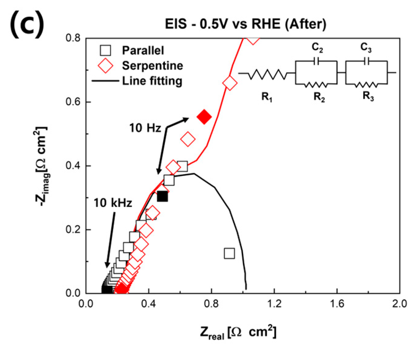
After the long-term durability evaluation, electrochemical characterizations were conducted. The polarization curves of fuel cells with different flow fields are shown in Figure 4a. The maximum power density of the PEMFC with the serpentine flow field was reduced from 419.5 to 64.96 mW/cm2 (−354.54 mW/cm2, −84.51%). Furthermore, the maximum power density of the fuel cell with the parallel flow field decreased from 391.78 to 270.71 mW/cm2 (−121.07 mW/cm2, −30.90%). As shown in Figure 4a, the effect of NaCl solutions on electrochemical characterizations of the fuel cell with the serpentine flow field was more fatal than with the parallel flow field. The Nyquist plots after the long-term durability evaluation are shown in Figure 4b,c. The faradaic resistance of the fuel cells increased more than the ohmic resistance in both the parallel and serpentine flow field cases compared with the EIS results after the long-term durability evaluation with the EIS, as shown in Figure 2b. In the case of the parallel flow field, the ohmic resistance increased by 0.017 Ω∙cm2 (+14.5%) after the long-term durability evaluation, and the faradaic resistance increased by 0.368 Ω∙cm2 (+71.04%). Notably, the ohmic resistance of the PEMFC using the serpentine flow field increased by 0.123 Ω∙cm2 (+96.09%), and the faraday resistance increased by 2.737 Ω∙cm2 (+514.47%). It implies that when the air was supplied with a NaCl solution for a long time, the faradaic resistance of the fuel cell was significantly increased compared to the ohmic resistance. These results are similar to the result of prior reports [29,33]. TPBs were decreased because of the humidification of the NaCl solution. In addition, it was confirmed that the effects of the NaCl solution were more critical in the serpentine flow field than in the parallel flow field.
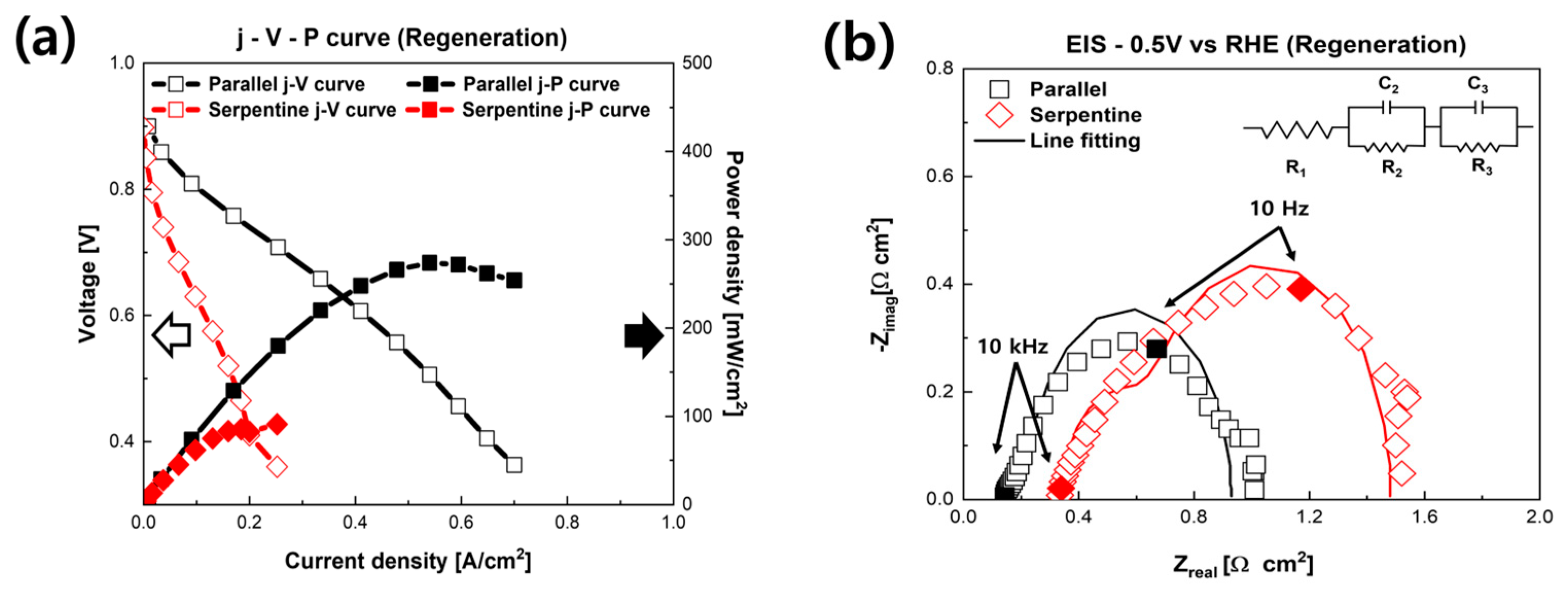
After the characterizations, regeneration evaluations were carried out. For regeneration, it is essential to remove the Na and Cl in fuel cells that adversely affect the PEMFCs. Pure DI water was supplied to remove Na and Cl. The Pt catalyst, GDL, gasket, and flow field were cleaned by supplying DI water to the cathode of the fuel cell. In addition, it was operated for 5 h in the high current region (0.4 V) to use the water generated by electrochemical reactions. The j-V-P curves of the regenerated PEMFCs are shown in Figure 5a. Notably, there were differences in recovery according to the flow field of the fuel cells. The maximum power density of the PEMFC using the parallel flow field was 274 mW/cm2 (+3.29 mW/cm2) after regeneration, which was recovered by 1.21%. However, the PEMFC with the serpentine flow field achieved 52.96% recovered performance, from 64.95 to 99.4 mW/cm2 (+34.4 mW/cm2). The PEMFC with the serpentine flow field was recovered around 3.5 times more than the PEMFC with the parallel flow field. Figure 5b shows Nyquist plots of the PEMFC after the regeneration process measured at 0.5 V. Interestingly, the ohmic resistance was not discernibly recovered; however, the faradaic resistance of the fuel cell was significantly decreased, i.e., recovered. The faradaic resistance of the parallel flow field was reduced to 0.786 Ω∙cm2 (−0.1 Ω∙cm2) from 0.886 Ω∙cm2, recovering 7.46%. Furthermore, the faradaic resistance of the serpentine flow field was recovered by 77.90%, from 3.269 to 1.137 Ω∙cm2 (−2.132 Ω∙cm2). The faradaic resistance decreased in both the parallel and serpentine flow fields with the DI water supply.
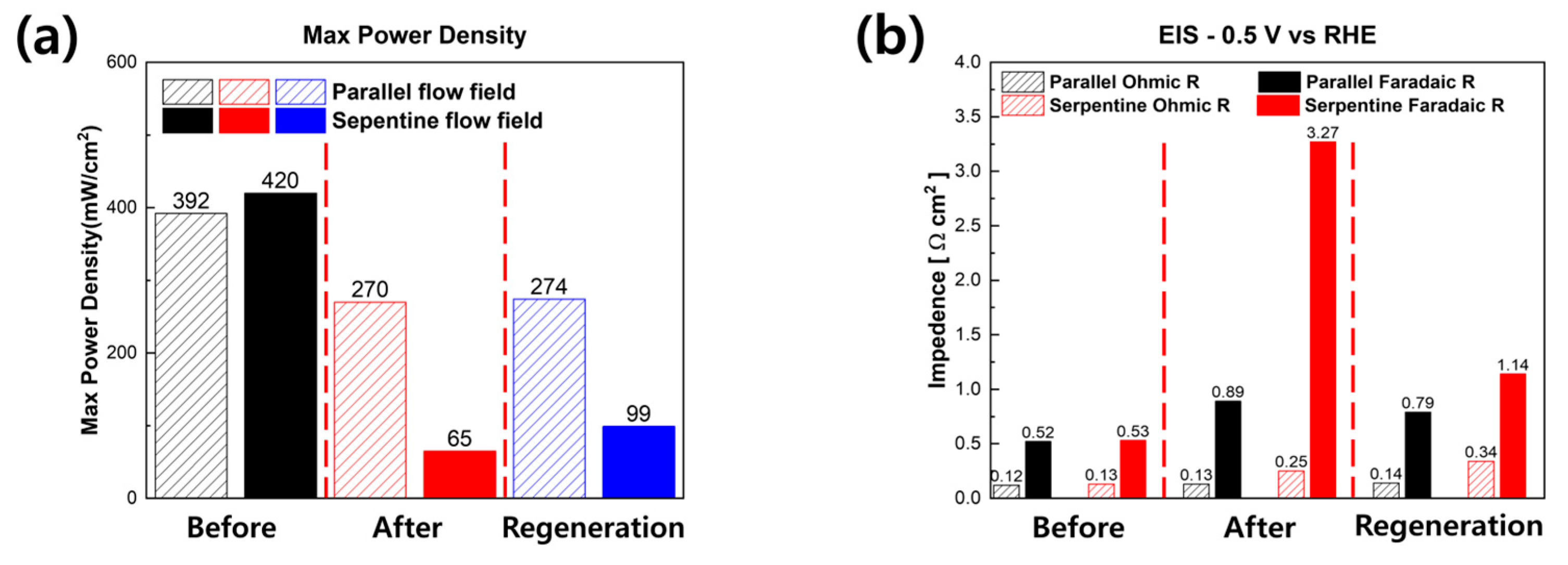
Figure 6 summarizes the results of all experiments. Figure 6a shows the maximum power density of the PEMFCs with different flow fields. As mentioned above, the performance degradation because of the effects of the NaCl solution was significantly more severe in the serpentine flow field than in the parallel flow field. After the long-term durability evaluation, the maximum power density of all fuel cells decreased. The PEMFC of the parallel flow field showed a 30.9% decreased performance after long-term stability. However, in the case of the fuel cell with a serpentine flow field, performance decreased by 84.52%. After long-term durability evaluation, regeneration was conducted with DI water. As a result of the regeneration, the performance of the fuel cell with the parallel flow field was recovered by 3.29 mW/cm2. However, the performance of the PEMFC with the serpentine flow field was recovered by 34.4 mW/cm2.
A summary of the EIS analysis results is shown in Figure 6b. After long-term durability evaluation, the faradaic resistances of the fuel cells were dramatically increased. Particularly, the faradaic resistance of the PEMFC with the serpentine flow field was increased by almost 6 times. Interestingly, after the regeneration experiments, which were carried out at a 0.4 V constant voltage mode with DI water, the faradaic resistances of the fuel cells were decreased. In particular, the faradaic resistance of the fuel cell with the serpentine flow field decreased by 77.90%. Therefore, the performance of the fuel cell with the serpentine flow field was increased to 99.4 from 64.95 mW/cm2.

4. Conclusions

In this study, the effects of a NaCl solution on the electrochemical characteristics of PEMFCs with different flow fields were systematically examined. A custom-made humidification system was prepared and used to supply NaCl solution based on an ultrasonic vibrator. Chronoamperometry was measured to evaluate the long-term durability of fuel cells humidified with NaCl solution. After 20 h of long-term durability evaluations, the performance of the fuel cells was significantly decreased. Interestingly, the performance of the PEMFC with the serpentine flow field was crucially decreased (−84.51%) compared with the performance of the fuel cell with the parallel flow field (−30.91%). In EIS analysis, the faradaic resistance was severely increased in the fuel cell with the serpentine flow field. After long-term examinations, regeneration experiments at 0.4 V were performed with DI water for 5 h. After the regenerations, the performance of the fuel cells was recovered because of the cleansing of Na and Cl from the fuel cell. Notably, the performance of the fuel cell with the serpentine flow field recovered more effectively (+52.96%) than the performance of the fuel cell with the parallel flow field (+1.22%) after regeneration because of the significantly reduced faradaic resistance (−2.132 Ω∙cm2 with the serpentine flow field vs. −0.1 Ω∙cm2 with the parallel flow field). We believe that the results of this study will provide insights into the marine application of PEMFCs.

Author Contributions

Writing—original draft, H.J.Y.; writing—review and editing, G.Y.C. All authors have read and agreed to the published version of the manuscript.

Funding

This research was partially supported by a Korea Institute Energy Technology Evaluation and Planning (KETEP) grant funded by the Korean government (MOTIE) (No. 20213030030260), an Institute for Information and communications Technology Promotion (IITP) grant funded by the Korean Government (MSIT), and a Korea Institute for Advancement of Technology (KIAT) grant funded by the Korean Government (MOTIE) (P0017120, The Competency Development Program for Industry Specialists).

Institutional Review Board Statement

Not applicable.

Informed Consent Statement

Not applicable.

Data Availability Statement

Not applicable.

Conflicts of Interest

The authors declare no conflict of interest.

References

  1. O’Hayre, R.; Cha, S.-W.; Colella, W.; Prinz, F.B. Fuel Cell Fundamentals; John Wiley & Sons: Hoboken, NJ, USA, 2016. [Google Scholar] [CrossRef]
  2. Costamagna, P.; Srinivasan, S. Quantum jumps in the PEMFC science and technology from the 1960s to the year 2000. J. Power Sources 2001, 102, 242–252. [Google Scholar] [CrossRef]
  3. Kirubakaran, A.; Jain, S.; Nema, R.K. A review on fuel cell technologies and power electronic interface. Renew. Sustain. Energy Rev. 2009, 13, 2430–2440. [Google Scholar] [CrossRef]
  4. Patil, A.S.; Dubois, T.G.; Sifer, N.; Bostic, E.; Gardner, K.; Quah, M.; Bolton, C. Portable fuel cell systems for America’s army: Technology transition to the field. J. Power Sources 2004, 136, 220–225. [Google Scholar] [CrossRef]
  5. Tang, Y.; Yuan, W.; Pan, M.; Wan, Z. Experimental investigation on the dynamic performance of a hybrid PEM fuel cell/battery system for lightweight electric vehicle application. Appl. Energy 2011, 88, 68–76. [Google Scholar] [CrossRef]
  6. Shih, N.-C.; Weng, B.-J.; Lee, J.-Y.; Hsiao, Y.-C. Development of a small fuel cell underwater vehicle. Int. J. Hydrogen Energy 2013, 38, 11138–11143. [Google Scholar] [CrossRef]
  7. Pan, Z.F.; An, L.; Wen, C.Y. Recent advances in fuel cells- based propulsion systems for unmanned aerial vehicles. Appl. Energy 2019, 240, 473–485. [Google Scholar] [CrossRef]
  8. Keim, M.; Kallo, J.; Friedrich, K.A.; Werner, C.; Saballus, M.; Gores, F. Multifunctional fuel cell system in an aircraft environment: An investigation focusing on fuel tank inerting and water generation. Aerosp. Sci. Technol. 2013, 29, 330–338. [Google Scholar] [CrossRef] [Green Version]
  9. Wang, B.; Zhao, D.; Li, W.; Wang, Z.; Huang, Y.; You, Y.; Becker, S. Current technologies and challenges of applying fuel cell hybrid propulsion systems in unmanned aerial vehicles. Prog. Aerosp. Sci. 2020, 116, 100620. [Google Scholar] [CrossRef]
  10. Javed, S.M.; Ahmad, Z.; Ahmed, S.; Iqbal, S.; Naqvi, I.J.; Usman, M.; Ashiq, M.N.; Elnaggar, A.Y.; El-Bahy, Z.M. Highly dispersed active sites of Ni nanoparticles onto hierarchical reduced graphene oxide architecture towards efficient water oxidation. Fuel 2022, 312, 122926. [Google Scholar] [CrossRef]
  11. Ahmad, Z.; Maqbool, A.; Hussain, M.A.; Pashameah, R.A.; Shahzadi, A.; Nazar, N.; Iqbal, S.; Alanazi, A.K.; Ashiq, M.N.; Abo-Dief, H.M. One-pot solvothermal synthesis of highly catalytic Janus transition metal phosphides (TMPs) for high per-formance OER. Fuel 2023, 331, 125913. [Google Scholar] [CrossRef]
  12. Reshetenko, T.V.; Bender, G.; Bethune, K.; Rocheleau, R. A segmented cell approach for studying the effects of serpentine flow field parameters on PEMFC current distribution. Electrochim. Acta 2013, 88, 571–579. [Google Scholar] [CrossRef]
  13. Spernjak, D.; Prasad, A.K.; Advani, S.G. In situ comparison of water content and dynamics in parallel, single-serpentine, and interdigitated flow fields of polymer electrolyte membrane fuel cells. J. Power Sources 2010, 195, 3553–3568. [Google Scholar] [CrossRef]
  14. Jiao, K.; Park, J.; Li, X. Experimental investigations on liquid water removal from the gas diffusion layer by reactant flow in a PEM fuel cell. Appl. Energy 2010, 87, 2770–2777. [Google Scholar] [CrossRef]
  15. Le, A.D.; Zhou, B. A general model of proton exchange membrane fuel cell. J. Power Sources 2008, 182, 197–222. [Google Scholar] [CrossRef]
  16. Zhang, Q.; Lin, R.; Técher, L.; Cui, X. Experimental study of variable operating parameters effects on overall PEMFC performance and spatial performance distribution. Energy 2016, 115, 550–560. [Google Scholar] [CrossRef]
  17. Yoshida, T.; Kojima, K. Toyota MIRAI Fuel Cell Vehicle and Progress Toward a Future Hydrogen Society. Interface Mag. 2015, 24, 45–49. [Google Scholar] [CrossRef]
  18. Bi, H.T.; Sauriol, P.; Stumper, J. Two-phase flow distributors for fuel cell flow channels. Particuology 2010, 8, 582–587. [Google Scholar] [CrossRef]
  19. Boddu, R.; Marupakula, U.K.; Summers, B.; Majumdar, P. Development of bipolar plates with different flow channel configurations for fuel cells. J. Power Sources 2009, 189, 1092. [Google Scholar] [CrossRef]
  20. Lim, B.H.; Majlan, E.H.; Daud, W.R.W.; Husaini, T.; Rosli, M.I. Effects of flow field design on water management and reactant distribution in PEMFC: A review. Ionics 2016, 22, 301–316. [Google Scholar] [CrossRef]
  21. Misran, E.; Hassan, N.S.M.; Daud, W.R.W.; Majlan, E.H.; Rosli, M.I. Water transport characteristics of a PEM fuel cell at various operating pressures and temperatures. Int. J. Hydrogen Energy 2013, 38, 9408. [Google Scholar] [CrossRef]
  22. Kim, D.K.; Koh, J.S.; Kim, M.S.; Song, H.H. Experimental and computational study on the dynamic interaction be-tween load variation and back pressure control in a polymer electrolyte membrane fuel cell for automotive application. Int. J. Hydrogen Energy 2015, 40, 12381. [Google Scholar] [CrossRef]
  23. Liu, H.; Li, P.; Juarez-Robles, D.; Wang, K.; Hernandez-Guerrero, A. Experimental Study and Comparison of Various De-signs of Gas Flow Fields to PEM Fuel Cells and Cell Stack Performance. Front. Energy Res. 2014, 2, 2. [Google Scholar] [CrossRef] [Green Version]
  24. Sando, Y. Research and Development of Fuel Cell Vehicles at Honda. ECS Trans. 2009, 25, 211–224. [Google Scholar] [CrossRef]
  25. Larminie, J.; Dicks, A. Fuel Cell Systems Analysed, Fuel Cell Systems Explained; John Wiley & Sons: Hoboken, NJ, USA, 2013; pp. 369–389. [Google Scholar] [CrossRef]
  26. Le, A.D.; Zhou, B. Fundamental understanding of liquid water effects on the performance of a PEMFC with serpentine-parallel channels. Electrochim. Acta 2009, 54, 2137–2154. [Google Scholar] [CrossRef]
  27. Wang, X.-D.; Duan, Y.-Y.; Yan, W.-M. Novel serpentine-baffle flow field design for proton exchange membrane fuel cells. J. Power Sources 2007, 173, 210–221. [Google Scholar] [CrossRef]
  28. Kim, H.; Kim, J.; Kim, D.; Kim, G.H.; Kwon, O.; Cha, H.; Choi, H.; Yoo, H.; Park, T. Mass diffusion characteristics on perfor-mance of polymer electrolyte membrane fuel cells with serpentine channels of different width. Int. J. Heat Mass Transf. 2022, 183, 122106. [Google Scholar] [CrossRef]
  29. Shimpalee, S.; Vanzee, J. Numerical studies on rib & channel dimension of flow-field on PEMFC performance. Int. J. Hydrogen Energy 2007, 32, 842–856. [Google Scholar] [CrossRef]
  30. Finlayson-Pitts, B.J.; Hemminger, J.C. Physical Chemistry of Airborne Sea Salt Particles and Their Components. J. Phys. Chem. A 2000, 104, 11463–11477. [Google Scholar] [CrossRef]
  31. Li, H.; Zhang, S.; Qian, W.; Yu, Y.; Yuan, X.Z.; Wang, H.; Jiang, M.; Wessel, S.; Cheng, T.T.H. Impacts of operating conditions on the effects of chloride contamination on PEM fuel cell performance and durability. J. Power Sources 2012, 218, 375–382. [Google Scholar] [CrossRef]
  32. Mikkola, M.S.; Rockward, T.; Uribe, F.A.; Pivovar, B.S. The Effect of NaCl in the Cathode Air Stream on PEMFC Performance. Fuel Cells 2007, 7, 153–158. [Google Scholar] [CrossRef]
  33. Ali, S.T.; Li, Q.; Pan, C.; Jensen, J.O.; Nielsen, L.P.; Møller, P. Effect of chloride impurities on the performance and durability of polybenzimidazole-based high temperature proton exchange membrane fuel cells. Int. J. Hydrogen Energy 2011, 36, 1628–1636. [Google Scholar] [CrossRef]
  34. Yan, W.-M.; Chu, H.-S.; Liu, Y.-L.; Chen, F.; Jang, J.-H. Effects of chlorides on the performance of proton exchange mem-brane fuel cells. Int. J. Hydrogen Energy 2011, 36, 5435–5441. [Google Scholar] [CrossRef]
  35. Veleva, L.; Farro, W. Influence of seawater and its aerosols on copper patina composition. Appl. Surf. Sci. 2012, 258, 10072–10076. [Google Scholar] [CrossRef]
  36. Carton, J.G.; Olabi, A.G. Design of experiment study of the parameters that affect performance of three flow plate con-figurations of a proton exchange membrane fuel cell. Energy 2010, 35, 2796–2806. [Google Scholar] [CrossRef] [Green Version]
  37. Dhahad, H.A.; Alawee, W.H.; Hassan, A.K. Experimental study of the effect of flow field design to PEM fuel cells performance. Renew. Energy Focus 2019, 30, 71–77. [Google Scholar] [CrossRef]
  38. Mojica, F.; Rahman, M.A.; Mora, J.M.; Ocon, J.D.; Chuang, P.Y.A. Experimental Study of Three Channel Designs with Model Comparison in a PEM Fuel Cell. Fuel Cells 2020, 20, 547–557. [Google Scholar] [CrossRef]
  39. Karthikeyan, M.; Karthikeyan, P.; Muthukumar, M.; Kannan, V.M.; Thanarajan, K.; Maiyalagan, T.; Hong, C.W.; Jothi, V.R.; Yi, S.C. Adoption of novel porous inserts in the flow channel of pem fuel cell for the mitigation of cathodic flooding. Int. J. Hydrogen Energy 2020, 45, 7863–7872. [Google Scholar] [CrossRef]
  40. Heidary, H.; Kermani, M.J.; Advani, S.G.; Prasad, A.K. Experimental investigation of in-line and staggered blockages in parallel flowfield channels of PEM fuel cells. Int. J. Hydrogen Energy 2016, 41, 6885–6893. [Google Scholar] [CrossRef]
  41. Lee, P.H.; Hwang, S.S. Performance Characteristics of a PEM Fuel Cell with Parallel Flow Channels at Different Cath-ode Relative Humidity Levels. Sensors 2009, 11, 9104–9121. [Google Scholar] [CrossRef] [PubMed] [Green Version]
  42. Le Canut, J.-M.; Abouatallah, R.M.; Harrington, D.A. Detection of Membrane Drying, Fuel Cell Flooding, and Anode Catalyst Poisoning on PEMFC Stacks by Electrochemical Impedance Spectroscopy. J. Electrochem. Soc. 2006, 153, A857. [Google Scholar] [CrossRef]
  43. Choi, H.; Kim, J.; Kwon, O.; Yoo, H.; Kim, H.; Cha, H.; Park, T. Observation of flooding-induced performance enhancement in PEMFCs. Int. J. Hydrogen Energy 2022, 47, 6259–6268. [Google Scholar] [CrossRef]
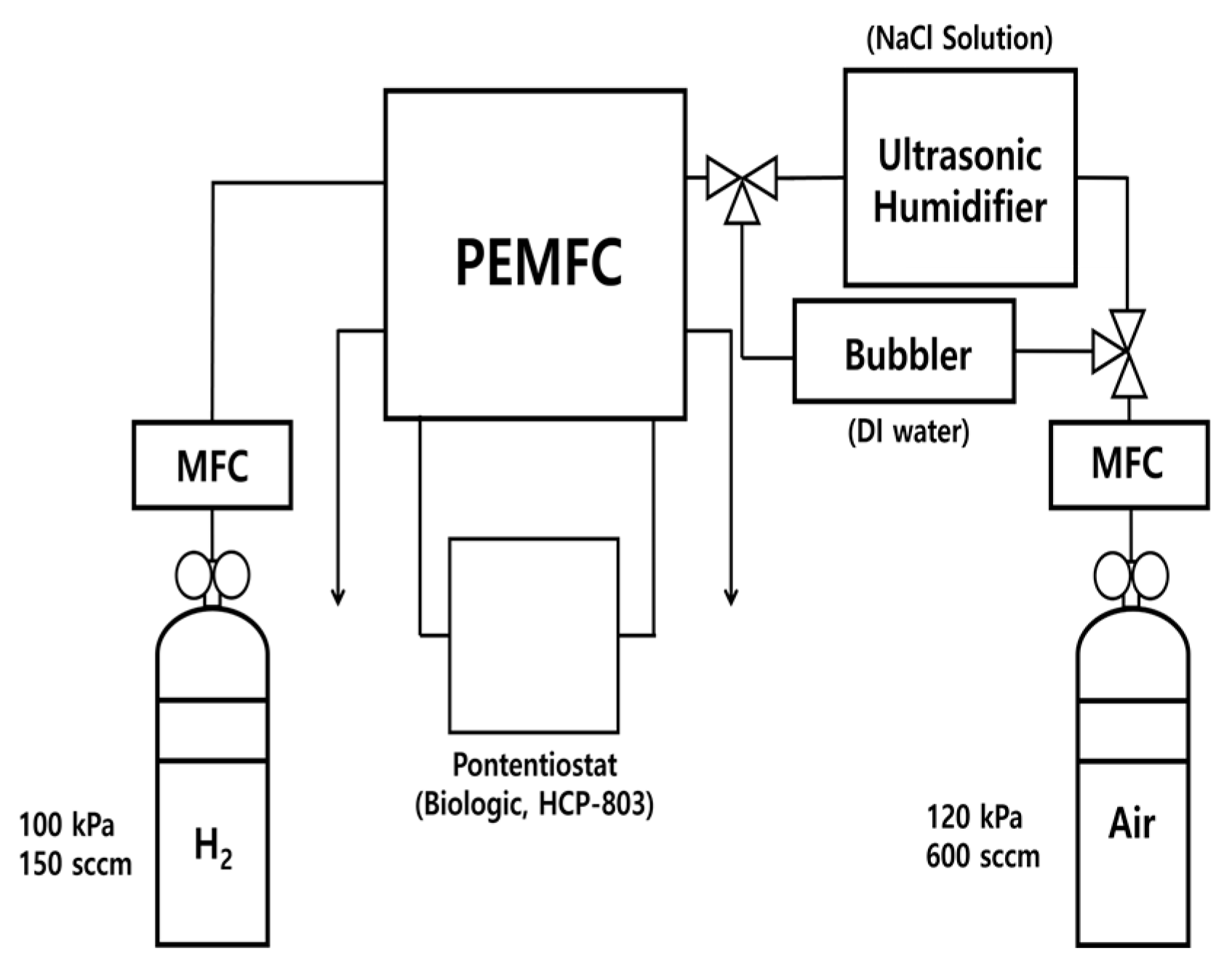
Figure 1. Schematics of the experimental setup.
Sustainability 15 02415 g001
Figure 2. Initial electrochemical characteristics of PEMFCs with different flow fields. (a) Polarization curves of fuel cells. (b) EIS results of fuel cells at 0.5 V.
Sustainability 15 02415 g002
Figure 3. Results of long-term stability evaluations of fuel cells with different flow fields.
Sustainability 15 02415 g003
Figure 4. Electrochemical characterizations of PEMFCs with different flow fields. (a) Polarization curves of fuel cells. Solid curves are the power density-voltage curves. (b) EIS results of fuel cells with different flow fields. (c) Partial enlargement of Nyquist plots. Solid point shows the frequency of the EIS.
Sustainability 15 02415 g004aSustainability 15 02415 g004b
Figure 5. Electrochemical performance of fuel cells after regeneration. (a) Polarization curves of fuel cells with different flow fields after regeneration. Solid curves are the power density-voltage curves. (b) Nyquist plots of fuel cells at 0.5 V with different flow fields after regeneration. Solid point shows the frequency of the EIS.
Sustainability 15 02415 g005
Figure 6. Summary of experiments. (a) Performances of fuel cells with different flow fields. Each blocks show the maximum power density measured at the initial, after the chronoamperometry, and after the regeneration (b) EIS results of PEMFCs with different flow fields.
Sustainability 15 02415 g006
Disclaimer/Publisher’s Note: The statements, opinions and data contained in all publications are solely those of the individual author(s) and contributor(s) and not of MDPI and/or the editor(s). MDPI and/or the editor(s) disclaim responsibility for any injury to people or property resulting from any ideas, methods, instructions or products referred to in the content.