Abstract
As a result of China’s urbanization, it has been a common phenomenon that adjacent deep excavations were constructed near underground structures, which can have a series of detrimental effects on existing tunnels. Thus, it is crucial to assess the tunnel response induced by the overlying excavation, with the aim of maintaining the safety and serviceability of operating tunnels. The shield tunnel is idealized as an infinite beam lying upon a three parameter Kerr-model and the vertical force equilibrium equation of the tunnel element is established. Then, a theoretical solution is derived for capturing the soil–tunnel interaction. To prove the accuracy of the proposed method, the calculation results are compared with field measurements, along with the data of finite element studies. Thereafter, a parametric analysis will be conducted to assess some characteristic factors for tunnel responses caused by overlying excavations, such as tunnel-excavation horizontal distance, tunnel bending stiffness, and the buried depth of the tunnel. The results indicate that the increase in the bending stiffness and the buried depth of tunnel, as well as the tunnel-excavation horizontal distance, will significantly alleviate the tunnel deformation. However, the inner force will be increased when increasing the tunnel bending stiffness.
1. Introduction
With the continued growth of urbanization in China, the commercial value of underground space is widely acknowledged by urban designers. To meet the continuous development requirements and to improve the urban infrastructure construction, increasingly deep excavation pits in the basements of tall buildings were built in close proximity to the existing subway line. However, due to the increment of unloading stress induced by the overlying excavation, there is a significant increase in the displacement and internal forces of the tunnels, which can cause the tunnels’ lining segments to crack, leakage of groundwater, and even distortion of the longitudinal rail tracks [1], and the safety and serviceability of existing tunnels could be threatened. Therefore, it is crucial to evaluate the existing tunnels’ behavior due to the adjacent deep excavation in geotechnical engineering. Over recent decades, the influence of adjacent excavation on existing tunnels has been investigated by using different methods, including measurements analysis [2,3,4,5], indoor testing [6,7], numerical analysis [8,9,10,11,12,13,14], and theoretical analysis [15,16,17,18,19,20,21].
Compared with the long-time experimental model tests and high-cost numerical analysis, the analytical method can serve as a simplified solution to assess the tunnel response caused by rapid overlying excavation. The analytical solution usually takes some presumption before establishing formulas, and it can provide valuable suggestions for the excavation design before the start of a project. Observing existing analytical methods [15,16,17,18,19,20,21], it can be noted that the two-stage method has been commonly selected to estimate the soil–tunnel interaction. Firstly, the unloading stress along the shield tunnel caused by an overlying excavation could be assessed by a Mindlin solution [22]. Secondly, the shield tunnel is idealized as an infinite beam resting upon the single-parameter Winkler-model [23] or a double-parameter Pasternak-model [24]. Combing these two different but connected stages, the adjacent existing tunnel response due to deep excavation will be derived.
Among the previous approaches, the Winkler-model and the Pasternak-model, due to their simplicity and convenience, have been widely used for estimating the soil–tunnel interaction [25,26,27]. However, the Winkler-model, ignoring the affection of the continuity of adjacent springs, will overvault the deflection and inner force along the length of beam. Although the Pasternak-model and the Vlasov-model [28] can account for a new shearing layer for simulating the soil continuity of an adjacent spring, they could not deal with the compression deformation. For the purpose of solving this problem, a three-parameters Kerr-model [29,30,31] was proposed. A fundamental feature of the three parameters model is the flexibility and convenience, because it determines the level of “continuity” of the deformation in the boundary between the loading and unloading soil surfaces [32]. This feature offers them the ability to correctly distribute soil stresses [33].
To develop a theoretical solution for estimating the effect of an overlying excavation on tunnel response, the shield tunnel is idealized as an infinite beam. Meanwhile, with the purpose of improving the level of “continuity” of deformation in the boundary between the loading and unloading soil surfaces, the three-parameters Kerr-model is adopted here to simulate soil–tunnel interactions. The accuracy of this study is proved by an existing finite element method and a field measurement. Then, parametric analysis is performed to figure out the effect of overlying excavation on the existing tunnel.
2. Establishment of Theoretical Method
The two-stage method is usually selected to estimate the tunnel response induced by adjacent excavation, which has been widely recognized as a conventional method in analyzing the interaction between soil and structure in geotechnical engineering. Therefore, this method is selected here for estimating the excavation–soil–tunnel interaction.
2.1. The Calculation of Unloading Stress
The tunnel–excavation relative location is illustrated in Figure 1, where the excavation length, width, and depth are idealized as L, B, and H, respectively. If we take the midpoint O of the foundation pit to be the origin of the planar coordinate system, the positive ξ-axis direction is set in the long side of the excavation, and the positive ŋ-axis direction is set in the short side of the excavation. To investigate the situation where the tunnel is not parallel to the excavation edge, an auxiliary coordinate system xO ‘y is established, and a global coordinate system around the tunnel axis is set with O ‘. Note that the x direction is along the direction of the tunnel axis, while the y direction is perpendicular to the x direction. The buried depth at the tunnel axis is denoted with z0, the shortest distance between the tunnel axis and the point O of the excavation center is denoted with d, and α is denoted as the x-ξ related angle. According to the theory of Mindlin’s formula [22] and the existing literature [19,20,21], the unloading stress q(x) along the tunnel is mainly induced by the unloading load at the excavation bottom, they can be described as below:
where p is the unloading vertical load at the excavation base. υ is the Poisson’s ratio of soil. R1 and R2 can be calculated as:
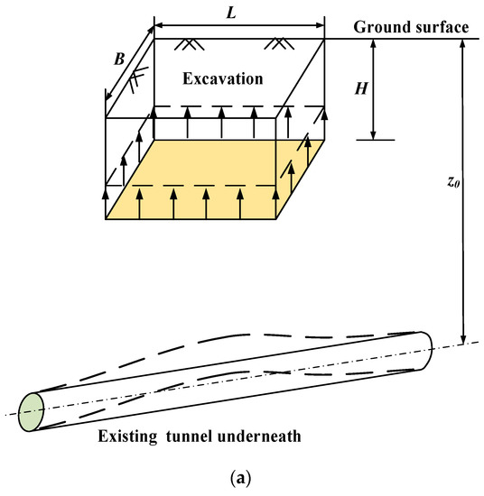
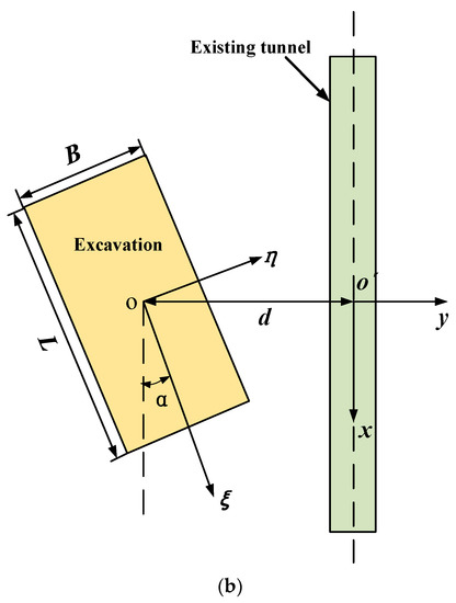
Figure 1.
Tunnel-excavation relative location. (a) over view. (b) plan view.
However, it is necessary to incorporate the plane coordinate system of the excavation into a global coordinate system in a real project. Then, the relation between the two coordinates is described as below:
Combing Equations (1)–(3), the unloading stress q(x) due to overlying excavation is calculated rapidly.
2.2. Theoretical Solution for Tunnel Deformation
Here, the existing tunnel is idealized as an infinite beam resting upon the three parameter Kerr-model (shown in Figure 2). Some assumptions can be found below:
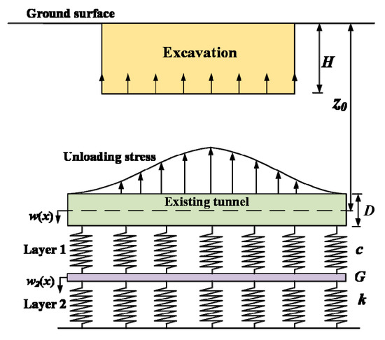
Figure 2.
The schematic of Kerr-model.
- (1)
- The existing tunnel can be idealized as a Euler–Bernoulli beam and the soil–tunnel interaction can be simulated as three-parameters Kerr-model.
- (2)
- The unloading stress due to foundation pit excavation is estimated by Mindlin’s formula, ignoring the influence of the existing tunnel.
- (3)
- The existing tunnel and the surrounding soil are co-deformed and have no local separation between them.
- (4)
- The influence of ground water and the variation of soil properties are ignored in this study.
According to the theoretical Kerr-model:
where w(x) is the displacement of tunnel, w1(x) and w2(x) are the displacement of layer 1 and 2 spring, respectively.
Assuming that p1(x) and p2(x) is denoted as the stress setting on the layer 1 and 2 spring, respectively, then:
where c and k are the stiffness of layer 1 and 2 spring, respectively.
Considering the force acting upon the layer 2 spring, p1(x) can be expressed as:
where G is a shear modulus of the Kerr-model.
Combining Equations (5) and (6):
Considering the theoretical of Euler–Bernoulli beam:
where M and EI are the bending moment and bending stiffness of the tunnel, respectively.
Considering the deformation of the tunnel element is illustrated in Figure 3, the vertical force balance equation about this element is obtained as:
where Q and M are the shear force and bending moment of the tunnel, respectively. dx is the tunnel element length, dQ and dM are the shear force and bending moment increment of the element along the tunnel direction, respectively. D is the diameter of tunnel.
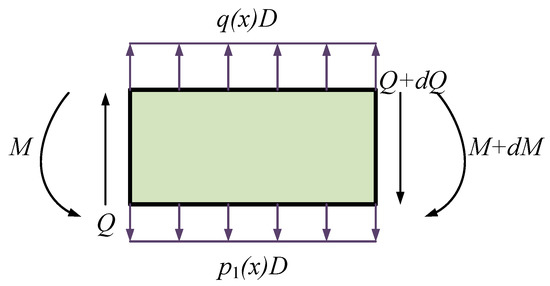
Figure 3.
Force analysis of element.
Meanwhile, the moment of shear layer Ms satisfies:
Combining Equations (7)–(10) yields:
In aiming to solve the Equation (11), the finite differential method is selected. Figure 4 shows the tunnel is divided into a length l = L1/n with n notes, L1 is the length of tunnel. Here, the elements of the tunnel are marked as 0, 1, …, n − 1, n from the left to right, successively. Meanwhile, there are six virtual elements marked as −3, −2, −1, and n + 1, n + 2, and n + 3 at the tunnel ends.
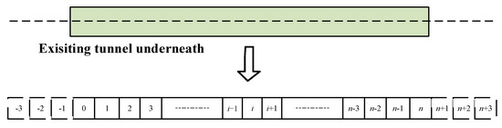
Figure 4.
The tunnel discretization.
Then Equation (11) can be rewritten as
where i = 0, 1, …., n−1, n. (w2)i is the deformation of layer 2 as shown in Figure 2. qi is the unloading stress as shown in Equation (1). Two ends of the tunnel can be idealized as they are free because of the assumption of the infinity of the tunnel. Therefore, the bending moment and shear force, as well as the bending moment of the shear layer at two tunnel ends can be idealized as 0. Then the solution of deformation w2 can be obtained as below:
where w2 and Qs are the column vector of deformation w2 and unloading stress q, respectively. K is the stiffness matrix of the tunnel. w2 and Qs can be expressed as:
K can be expressed as:
where
Therefore, the deformation of the layer 2 spring w2 is obtained. Considering the Euler–Bernoulli beam theoretically, the displacement and inner forces of tunnel can be calculated as below:
where
However, when the parameter c = 0, this study could be degenerated as the Pasternak-model (EB-P model). Meanwhile, when parameter c = 0 and G = 0, this study could be degenerated as the classic Winkler-model (EB-W model).
2.3. Determination of Parameters of Kerr-Model
Because the calculation accuracy of the behavior of the elastic beam is determined by parameters of the Kerr foundation model, so it is necessary to pay attention to ensure the parameter of the Kerr foundation model. In this paper, a modified three parameters relationship was proposed by Avramidis [34], for evaluating the parameters of this model by 2D FEM method, as follows:
where Es is the soil Yong’s modulus.
3. Verification of This Study
To test the efficacy of this study, a field measurement in Shanghai, and the results from a finite element study, are collected here to compare with the calculation results given by this study.
3.1. Comparing with FEM Method
Liang et al. [21] have analyzed the effect of an overlying excavation on an existing tunnel based on Plaxis 3D software. The length, width, and depth of the excavation are 8 m, 8 m, and 6 m, respectively. According to the proposal of Liang et al. [21], the size of the 3D model is 200 m × 200 m × 40 m. Meanwhile, in order to resist the action of horizontal earth pressure, four underground continuous walls with a length of 10 m were set up. The soil in this model is isotropic elastic, and the weight of the homogeneous soil is 18 KN/m3. The diameter of the tunnel is 12.4 m and the tunnel is located directly below the excavation and parallel to the long side of the excavation, the tunnel–excavation vertical clearance is 12.8 m. According to Shiba [35], the bending stiffness of the tunnel can be calculated as 7.8 × 10⁴ MN·m2. The other parameters in need are represented in Table 1.

Table 1.
Parameters of FEM method.
Figure 5 represents the calculated results of the tunnel deformation given by the finite element method (FEM), this study, the EB-P model, and the EB-W model. The deformation trends of the existing tunnel given by the four different calculation methods have a good consistency. Compared with the calculated result from the FEM, the prediction of the tunnel’s maximum deformation given by this study is slightly smaller. This may be attributed to the fact that the unloading load of the soil at the excavation bottom leads to the continuous reduction of the soil stiffness with the gradual excavation, and the solution obtained by the proposed method is difficult to take this influence of the weakening of soil stiffness into consideration. Meanwhile, the calculated results obtained by the EB-P and EB-W method will overestimate the deformation of the tunnel. This result may be ascribed to the three-parameter Kerr-model as it determines the level of “continuity” of the deformation in the boundary between the loading and unloading soil surfaces [32]. In general, Figure 5 indicates that the calculated results given by this study are closer to the FEM results than the ones from the EB-P and EB-W methods.
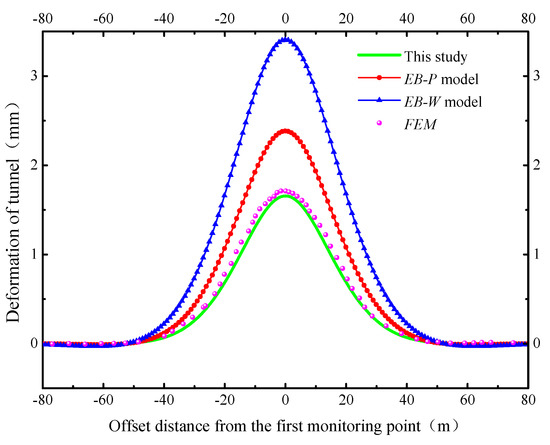
Figure 5.
Comparison of calculated and FEM results of deformation of tunnel.
3.2. Comparing with Measurements in Shanghai
An actual project has been reported by Huang et al. [13] and the relative position between an excavation and the shield tunnel are shown in Figure 6. Meanwhile, a corresponding finite element model is performed for clarifying the tunnel response due to the overlying excavation. The length, width, and depth of the nearly rectangular excavation are 50 m, 10 m, and 11 m, respectively. The outer diameter of the tunnel is 11 m with a lining thickness of 55 cm. The angle from the long side of the excavation to this tunnel’s centre line is 75°. The soil elastic modulus can be taken as 30.8 MPa. According to Shiba et al. [34], the bending stiffness of the tunnel can be calculated as 3.99 × 10⁵ MN·m2. Liang et al. [21] treated the tunnel as an infinite beam lying upon a Pasternak-model and the rationality of this model has been verified. The other parameters needed are shown in Table 2. The comparison between the finite element simulation, the existing method by Liang et al. [21], and the field measured data of the north line tunnel was conducted by Huang et al. [13]. A similar analysis will be conducted next.
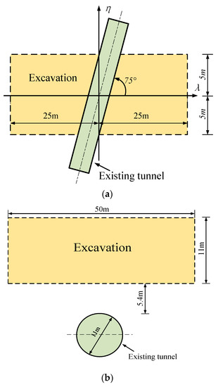
Figure 6.
Tunnel–excavation relative location. (a) plan view. (b) overview.
Table 2.
Parameters of Project in Shanghai.
Figure 7 represents the prediction of tunnel deformation given by this study, the existing method by Liang et al. [21] (shown as Liang method in Figure 7), FEM, and the field measurements. The deflection trends of the tunnel obtained from the three different solutions have a good consistency. Compared with the field measurements, the prediction results of the tunnel maximum deformation given by this study is slightly larger. It can be concluded that this phenomenon is because the behavior of the tunnel is limited by the separation of the tunnel wall, and this effect cannot be considered in this study. Meanwhile, compared with the calculation of this study, the results given by FEM are more close to the field measurements, the reason for this is that the results of FEM can take the effect of the tunnel separation wall into consideration. Compared with the prediction from Liang et al. [21], this study is coincides more with the field measurements. In general, Figure 7 indicates that the calculated results given by this study are closer to the FEM results and the field measurements. Therefore, the rationality of this study is verified.
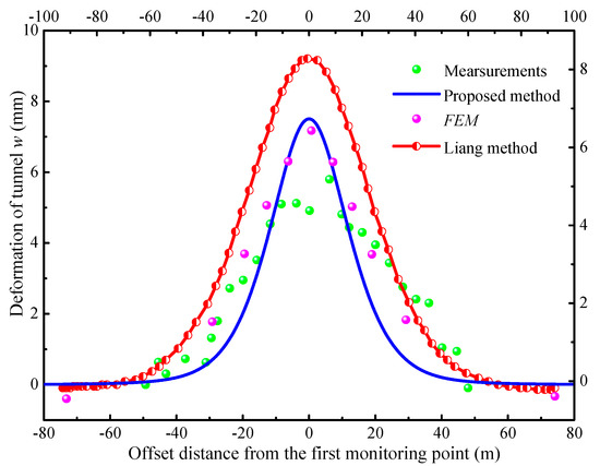
Figure 7.
Comparison of calculated, FEM, and measured results of deformation of tunnel.
4. Discussion
A series of factors are selected to analyze the effects of tunnel behaviors caused by overlying excavations, such as tunnel–excavation relative distance, tunnel bending stiffness, and tunnel depth. The length L, width B, and depth H of the excavation can be regarded as 40 m, 20 m, and 8 m, respectively. The short edge of the foundation pit is parallel with the tunnel. The soil of this model is assumed as homogeneous soil, and the unit weight, Young’s modulus, and Poisson’s ratio are generally taken as 10 KN/m3, 20 MPa, and 0.33, respectively. The depth of the tunnel centerline is set as 25 m and the original tunnel–excavation relative distance d = 0. The tunnel parameter can be considered as Yan’an Road tunnel case in Section 3.2.
4.1. Tunnel-Excavation Horizontal Distance
Figure 8 represents the existing tunnel response behavior induced by the overlying excavation in variation of the tunnel–excavation horizontal distance. The tunnel–excavation horizontal distance can be estimated with normalized distance d/(B/2).
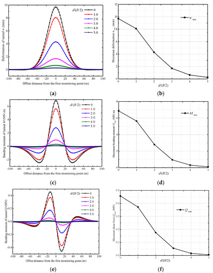
Figure 8.
Inner forces and deformation of tunnel in variation of d/(B/2). (a) Tunnel deformation. (b) Maximum tunnel deformation. (c) Tunnel Bending moment. (d) Maximum tunnel bending moment. (e) Tunnel shearing forces. (f) Maximum tunnel shearing forces.
Based on the calculation results from this study, the deformation, bending moment, and shearing forces of the tunnel generally decrease with the augmentation of horizontal distance d/(B/2) as illustrated in Figure 8a,c,e. The reason for this is that the greater the tunnel–excavation horizontal distance, the less tunnel response is caused by the adjacent excavation. Meanwhile, the maximum deformation, bending moment, and shearing forces of the existing tunnel also decreases with the increment of the horizontal distance d/(B/2) as illustrated in Figure 8b,d,f, and the responses of the tunnel fall sharply with d/(B/2), but at a subsequently lower rate. Meanwhile, the deformation and internal forces of the tunnel can be considered negligible when the horizontal distance d ≥ 3.0(B/2). It can be concluded that the unloading stress along the tunnel falls precipitously with the condition that the tunnel is located outside the range of the excavation in the aerial plane. From the observation of Figure 8, the maximum deformation and bending moments localize to the excavation center and the maximum shear force is located at 1.0(B/2), which localizes just below the excavation edge. Therefore, the tunnel segment in these positions may be more likely to be cracked.
4.2. Tunnel Bending Stiffness
To analyze the influence of tunnel bending stiffness on an existing tunnel induced by an overlying excavation, five values of tunnel bending stiffness were selected to figure out the influence of bending stiffness for tunnel behaviors. The tunnel bending stiffness EI can be regarded as 3.99 × 10⁵ MN·m, which is extracted from the project in Shanghai. To take this factor into consideration, the tunnel bending stiffness is assumed to be 0.1 EI, 0.5 EI, 1.0 EI, 5 EI, 10 EI, and 50 EI in this section. Based on the calculation results given by the proposed method, Figure 9 shows the overlying excavation induced responses of the existing tunnel with different bending stiffnesses.
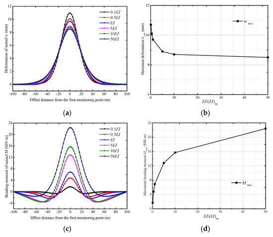
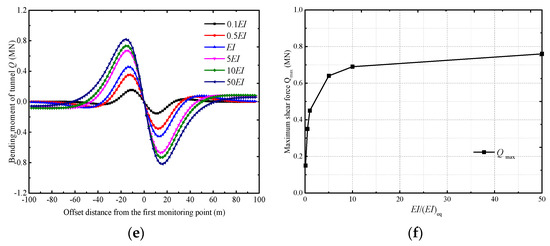
Figure 9.
Inner forces and deformation of tunnel in variation of tunnel bending stiffness. (a) Tunnel deformation. (b) Maximum tunnel deformation. (c) Tunnel Bending moment. (d) Maximum tunnel bending moment. (e) Tunnel shearing forces. (f) Maximum tunnel shearing forces.
From observation of Figure 9a,c,e, the increase of tunnel bending stiffness generally leads to a decrease in the deformation of the existing tunnel, but a significant increase in inner forces of the tunnel. This phenomenon may be caused because the tunnel resistance increases with the increment in tunnel bending stiffness, thereby resulting in the reduction of the tunnel response. Nevertheless, the inner force of the tunnel increases when the tunnel is subjected to the unloading stress. From observation of Figure 9b,d,f, the increase in tunnel bending stiffness results in a sharp decrease in the tunnel maximum deformation, but a sharp increase in the maximum inner forces of tunnel. However, the maximum deformation, bending moment, and shearing forces start to gradually approach stability when the tunnel bending stiffness is greater than 10. That is, the behavior response of the tunnel gets less sensitive to the change of tunnel bending stiffness at high bending stiffness levels (>10). Figure 9 also indicates that the location of the tunnel with maximum deformation and inner force, i.e., the weakest positions within the tunnel, does not change with the variation of bending stiffness. These may pose a great threat to the tunnel safety. It can therefore be found that tunnel bending stiffness is important for governing the tunnel response, and any variation in tunnel bending stiffness during the design stage should be given more attention.
4.3. Tunnel Depth
To analyze the influence of the tunnel depth on the existing tunnel due to the overlying excavation, five different depths of the tunnel axis are selected to figure out the influence of tunnel buried depth for tunnel behaviors. Figure 10 presents the calculation results of tunnel deformation and inner forces obtained by this study in variation of the depths of the tunnel axis. The buried depths of the tunnel axis can be denoted as 16 m, 20 m, 24 m, 28 m, and 32 m.
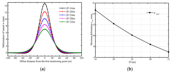
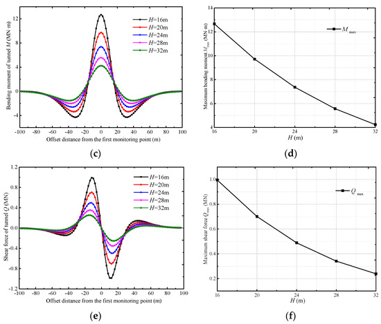
Figure 10.
Inner forces and deformation of tunnel in variation of tunnel buried depth. (a) Tunnel deformation. (b) Maximum tunnel deformation. (c) Tunnel Bending moment. (d) Maximum tunnel bending moment. (e) Tunnel shearing forces. (f) Maximum tunnel shearing forces.
From observation of Figure 10a,c,e, the deformation, bending moment, and shearing forces of the tunnel decrease significantly with the increase in tunnel depth, but at a slightly decreasing rate. This phenomenon can be concluded as the ground disturbance induced by the overlying excavation decreasing with the augmentation of the buried depth of the tunnel axis. From observation of Figure 10b,d,f, the maximum deformation and inner force of the existing tunnel fall precipitously with the augmentation of the buried depth of the tunnel axis, with a subsequently decreasing rate. From the observation of Figure 10, the behavior response of the tunnel decreases nonlinearly with the increment of the buried depth of the tunnel axis. This may be ascribed to the truth that the unloading stress due to the overlying excavation decreases nonlinearly with an increase in the tunnel-excavation vertical distance. In other words, based on this finding, it is useful to alleviate the response of the exiting tunnel through enlarging the vertical distance between the tunnel and the excavation.
5. Conclusions
In this study, an improved theoretical solution is introduced for evaluating the tunnel response caused by overlying excavation. Compared with the classic Winkler and Pasternak-model, the Kerr-model is adopted here to simulate the soil–tunnel interaction, which can determine the level of “continuity” of the deformation in boundary between the loading and unloading soil surfaces. Then, the two-stage method can be selected to investigate soil–tunnel interaction.
The rationality of this study is verified by FEM and an actual case in Shanghai. The prediction given by this study is closely consistent with FEM results and field measurements. In contrast to the existing solutions given by the Pasternak-model and Winkler-model, the calculation results of this study yield a much better accuracy to FEM data and field measurements.
The parameter analysis indicates that the tunnel-excavation relative distance, tunnel bending stiffness, and the tunnel depth are the key design factors for tunnel responding induced by an overlying excavation. The increment of tunnel-excavation relative distance could significantly reduce the deformation and inner force of the tunnel, such that the tunnel response can be controlled safely under the condition that the tunnel is located outside the excavation range in the aerial plane. Furthermore, the increment of the tunnel bending stiffness would result in a significant decrease in the tunnel deformation, but an increase in the inner force of tunnel. The increment of the buried depth of the tunnel axis could result in a nonlinear decrease in the deformation and inner force of the tunnel. In addition, the maximum strain and bending moment localizes to the excavation center, but the maximum shearing forces localizes just below the excavation edge. This improved theoretical solution would be applied for estimating the tunnel response due to the overlying excavation in real engineering projects.
This improved theoretical solution cannot consider local separation in the tunnel–soil interaction. The influence of ground water and the variation of soil properties are also ignored. These shortcomings will be taken into account in future studies.
Author Contributions
Conceptualization, G.F. and Q.C.; software, G.F.; validation, P.W. and F.S.; formal analysis, G.F.; investigation, Q.C.; data curation, P.W. and F.S; writing—original draft preparation, G.F.; writing—review and editing, Q.C.; visualization, Y.L. and Z.S.; supervision, C.X.; funding acquisition, C.X. All authors have read and agreed to the published version of the manuscript.
Funding
This research was funded by the National Natural Science Foundation of China, grant number 52238009, 51878276, U1934208, and 52008373; the Natural Science Foundation of Jiangxi Province, grant number 20223BBG71018; and the Centre for Balance Architecture of Zhejiang University, grant number 20203512-10C.
Institutional Review Board Statement
Not applicable.
Informed Consent Statement
Not applicable.
Data Availability Statement
Not applicable.
Conflicts of Interest
The authors declare no conflict of interest.
References
- Chang, C.; Sun, C.; Duann, S.; Richard, N. Response of a Taipei Rapid Transit System (TRTS) tunnel to adjacent excavation. Tunn. Undergr. Space Technol. 2001, 16, 151–158. [Google Scholar] [CrossRef]
- Hu, Z.; Yue, Z.; Zhou, J.; Tham, L.G. Design and construction of a deep excavation in soft soils adjacent to the Shanghai Metro tunnels. Can. Geotech. J. 2003, 40, 933–948. [Google Scholar] [CrossRef]
- Wang, J.; Xu, Z.; Wang, W. Wall and Ground Movements due to Deep Excavations in Shanghai Soft Soils. J. Geotech. Geo-Environ. Eng. 2010, 136, 985–994. [Google Scholar] [CrossRef]
- Khoiri, M.; Ou, C.Y. Evaluation of deformation parameter for deep excavation in sand through case histories. Comput. Geotech. 2013, 47, 57–67. [Google Scholar] [CrossRef]
- Cao, C.; Shi, C.; Lei, M.; Peng, L.; Bai, R. Deformation Characteristics and Countermeasures of shallow and Large-span Tunnel Under-crossing the Existing Highway in Soft Soil: A Case Study. SCE J. Civ. Eng. 2018, 22, 3170–3181. [Google Scholar] [CrossRef]
- Zheng, G.; Wei, S.; Peng, S.; Diao, Y.; Ng, C.W. Centrifuge modeling of the influence of basement excavation on existing tunnels. In Proceedings of the International Conference on Physical Modelling in Geotechnics, Zurich, Switzerland, 28 June–1 July 2010; Volume 1, pp. 523–527. [Google Scholar]
- Ng, C.W.; Shi, J.; Hong, Y. Three-dimensional centrifuge modelling of basement excavation effects on an existing tunnel in dry sand. Can. Geotech. J. 2013, 50, 874–888. [Google Scholar] [CrossRef]
- Chen, Y. Research on the Heave Displacement of Tunnel Induced by Foundation pit. Master’s Thesis, Tongji University, Shanghai, China, 2005. [Google Scholar]
- Liu, H.; Li, P.; Liu, J. Numerical investigation of underlying tunnel heave during a new tunnel construction. Tunn. Undergr. Space Technol. 2011, 26, 276–283. [Google Scholar] [CrossRef]
- Zheng, G.; Wei, S. Numerical analyses of influence of overlying pit excavation on existing tunnels. J. Cent. South Univ. Technol. 2008, 15, 69–75. [Google Scholar] [CrossRef]
- Shi, J.; Ng, C.W.; Chen, Y. Three-dimensional numerical parametric study of the influence of basement excavation on existing tunnel. Comput. Geotech. 2015, 63, 146–158. [Google Scholar] [CrossRef]
- Shi, C.; Cao, C.; Lei, M.; Peng, L.; Ai, H. Effects of lateral unloading on the mechanical and deformation performance of shield tunnel segment joints. Tunn. Undergr. Space Technol. 2016, 51, 175–188. [Google Scholar] [CrossRef]
- Huang, H.; Huang, X.; Schweiger, H.F. Numerical analysis of the influence of deep excavation on underneath existing road tunnel. Chin. Civ. Eng. J. 2012, 45, 182–189. [Google Scholar]
- Afifipour, M.; Sharifzadeh, M.; Shahriar, K.; Jamshidi, H. Interaction of twin tunnels and shallow foundation at Zand underpass, Shiraz metro, Iran. Tunn. Undergr. Space Technol. 2011, 26, 356–363. [Google Scholar] [CrossRef]
- Liao, S.; Peng, F.; Shen, S. Analysis of shearing effect on tunnel induced by load transfer along longitudinal direction. Tunn. Undergr. Space Technol. 2008, 23, 421–430. [Google Scholar] [CrossRef]
- Zhang, Z.; Zhang, M.; Wang, W. Two-stage method for analyzing effects on adjacent metro tunnels due to foundation pit excavation. Rock Soil Mech. 2011, 32, 2085–2092. [Google Scholar]
- Zhang, Z.; Huang, M. Boundary element model for analysis of the mechanical behavior of existing pipelines subjected to tunneling-induced deformations. Comput. Geotech. 2012, 81, 93–103. [Google Scholar] [CrossRef]
- Zhang, Z.; Huang, M.; Wang, W. Evaluation of deformation response for adjacent tunnels due to soil unloading in excavation engineering. Tunn. Undergr. Space Technol. 2013, 38, 244–253. [Google Scholar] [CrossRef]
- Feng, G.; Xu, C.; Liang, L.; Tey, M.; Chi, M.; Ge, S. Simplified method for evaluating the response of existing tunnel induced by adjacent excavation. Int. J. Numer. Anal. Methods Geomech. 2023, 47, 54–81. [Google Scholar] [CrossRef]
- Liang, R.; Xia, T.; Huang, M.; Lin, C. Simplified method for evaluating the effects of adjacent excavation on shield tunnel considering the shearing effect. Comput. Geotech. 2017, 81, 167–187. [Google Scholar] [CrossRef]
- Liang, R.; Wu, W.; Yu, F.; Jiang, G.; Liu, J. Simplified method for evaluating shield tunnel deformation due to adjacent excavation. Tunn. Undergr. Space Technol. 2018, 71, 94–105. [Google Scholar] [CrossRef]
- Mindlin, R.D. Force at a Point in the Interior of a Semi-Infinite Solid. Physics 1936, 7, 195–202. [Google Scholar] [CrossRef]
- Winkler, E. Die Lehre von der Elastizitat und Festigkeit (The Theory of Elasticity and Stiffness); Dominicus Prague: Czechoslovakia, Germany, 1867. [Google Scholar]
- Pasternak, P.L. On a New Method of Analysis of an Elastic Foundation by Means of Two Foundation Constants; Gosudarstvennoe Izdatelstvo Literaturi po Stroitelstvu I Arkhitekture: Moscow, Russia, 1954. [Google Scholar]
- Wu, H.; Shen, S.; Liao, S.; Yin, Z. Longitudinal structural modelling of shield tunnels considering shearing dislocation between segmental rings. Tunn. Undergr. Space Technol. 2015, 50, 317–323. [Google Scholar] [CrossRef]
- Wu, H.; Shen, S.; Yang, J.; Zhou, A. Soil-tunnel interaction modelling for shield tunnels considering shearing dislocation in longitudinal joints. Tunn. Undergr. Space Technol. 2018, 78, 168–177. [Google Scholar] [CrossRef]
- Liu, J.; Shi, C.; Lei, M.; Cao, C.; Lin, Y. Improved analytical method for evaluating the responses of a shield tunnel to adjacent excavations and its application. Tunn. Undergr. Space Technol. 2020, 98, 103339. [Google Scholar] [CrossRef]
- Vlasov, V.Z.; Leontev, U.N. Beams, Plates and Shells on Elastic Foundations; Israel Program for Scientific Translations: Jerusalem, Russia, 1966. [Google Scholar]
- Kerr, A.D. Elastic and viscoelastic foundation models. Appl. Mech. 1964, 25, 491–498. [Google Scholar] [CrossRef]
- Kerr, A.D. A study of a new foundation model. Acta Mech. 1965, 1, 135–147. [Google Scholar] [CrossRef]
- Kerr, A.D. On the determination of foundation model parameters. Geotech. Engrg. 1985, 111, 1334–1340. [Google Scholar] [CrossRef]
- Hetenyi, M. A general solution for the bending of beams on an elastic foundation of arbitrary continuity. J. Appl. Phys. 1950, 21, 55–58. [Google Scholar] [CrossRef]
- Reissner, E. Note on the formulation of the problem of the plate on an elastic foundation. Acta Mech. 1967, 4, 88–91. [Google Scholar] [CrossRef]
- Avramidis, I.E.; Konstantinos, M. Bending of beams on three-parameter elastic foundation. Int. J. Solids Struct. 2006, 43, 357–375. [Google Scholar] [CrossRef]
- Shiba, Y.; Kawashima, K.; Obinata, N. Evaluation method of longitudinal stiffness of shield tunnel linings for application to seismic response analysis. Proc. Jpn. Soc. Civil Eng. 1988, 398, 319–327. [Google Scholar]


Disclaimer/Publisher’s Note: The statements, opinions and data contained in all publications are solely those of the individual author(s) and contributor(s) and not of MDPI and/or the editor(s). MDPI and/or the editor(s) disclaim responsibility for any injury to people or property resulting from any ideas, methods, instructions or products referred to in the content. |
© 2023 by the authors. Licensee MDPI, Basel, Switzerland. This article is an open access article distributed under the terms and conditions of the Creative Commons Attribution (CC BY) license (https://creativecommons.org/licenses/by/4.0/).