Article

Performance of Enhanced Problematic Soils in Roads Pavement Structure: Numerical Simulation and Laboratory Study

by
Gamil M. S. Abdullah
Civil Engineering Department, College of Engineering, Najran University, Najran 55461, Saudi Arabia
Sustainability 2023, 15(3), 2595; https://doi.org/10.3390/su15032595
Submission received: 9 January 2023 / Revised: 27 January 2023 / Accepted: 29 January 2023 / Published: 1 February 2023

Abstract

:
The deficiency of high-quality soils in Saudi Arabia’s southern and northern regions, as well as along the Arabian Gulf coasts, is regarded as one of the most common issues with the construction of roads. High compressibility, low shear strength, substantial volume change (particularly in Sabkha), and low bearing capacity are the most typical issues with these problematic soils. In this study, finite element simulations were performed using the Plaxis 3D software v20 to simulate the performance and study the critical responses (fatigue, rutting strains, and damage ratio) of an enhanced pavement structure with a geogrid reinforcement resting on the naturally problematic Sabkha subgrade. A normal asphalt concrete layer, a base layer of Sabkha soil stabilized with Foamed Sulfur Asphalt (FSA), and a sand dune subbase layer comprised the pavement structure. For each layer, the model’s input parameters were a mix of laboratory and literature data. The simulation was performed on a pavement structure without reinforcement and on another section enhanced with a geogrid positioned at various locations to determine the ideal placement for lowering the important responses such as fatigue, rutting stresses, and damage ratio. The nonlinear behavior of an FSA–Sabkha base, sand subbase layer, and Sabkha subgrade was simulated using the hardening soil model, whereas the asphaltic concrete layer and geogrid material were simulated using the linear elastic model. The findings of the simulations demonstrated that placing geogrid reinforcement at the top of the subgrade layer resulted in the greatest reduction in horizontal tensile (fatigue) and vertical compressive (rutting) strains, as well as vertical displacement (32.71%, 13.2%, and 14.2%, respectively). In addition, geogrid reinforcement greatly reduced the fatigue damage ratio (33% to 55%), although the reduction in the rutting damage ratio was slightly lower (14% to 30%). The simulation results were validated using a wheel tracking machine and it was clear that there is a reasonable agreement between the results.

1. Introduction

Marginal and problematic soils such as dune sand and Sabkha cover wide areas in the eastern, southern, and western portions of the Kingdom of Saudi Arabia and the Arabian Gulf shoreline. Generally, Sabkha soils can be defined as evaporative flats and salt-encrusted with a high proportion of organic matter. This unique type of soil is referred to as “Sabkha” in Arabic; other names for it include saline soils and evaporate soils. Indeed, Sabkha soils are more prone to form in hot, arid areas with higher evaporation rates than precipitation. The characteristics of Sabkha soil are extremely unusual. Typically, it has a loose, porous, permeable texture that ranges from sandy to granular. The terrain of Sabkha changes with the seasons as well. For instance, it varies from a very smooth crust to a weak polygonal shape and flat, uneven units during the dry season of the year. Akili [1] reported that Sabkha soil covers 20% of the Arabian Gulf coastal strip area, approximately 50,000 km2, i.e., 1000 km long with 50 km wide. Figure 1 shows Sabkha soil distribution in the Kingdom of Saudi Arabia and the shoreline of the Arabian Gulf. The construction of roads in these areas without using the available local marginal soils, i.e., dune sand and Sabkha, is not cost beneficial, not to mention the scarcity of good construction materials. Stabilization of the marginal and problematic soils including Sabkha soil has proved its effectivity in enhancing their engineering properties, which can be performed with any suitable stabilizers such as cement, cement kiln dust, emulsion asphalt, foamed asphalt, Emulsified Sulfur Asphalt (ESA), Foamed Sulfur Asphalt (FSA) [2,3,4,5], lime, and many other familiar chemical stabilizers and fabric stated in literature [6].
The first studies on Sabkha soil were performed by Asi et al. [9,10], who conducted a number of laboratory tests to assess the viability of using foamed asphalt technology in Saudi Arabia to enhance the dune sands or Sabkha soils for potential use as a base or subbase material in the pavement structure. In order to establish design techniques for the potential application of foamed asphalt technology in the challenging climatic circumstances of eastern Saudi Arabia, several parameters were examined to assess the relative improvement of local soils. The effects of foamed asphalt treatment, both with and without the addition of Portland cement, on the strength properties of the treated mixtures were confirmed using statistical analysis of the data. The performance of foamed asphalt mixtures was found to be significantly better than that of the emulsified asphalt mixtures, according to the results exhibited. A previous experimental program (Al-Homidy et al., [3]) was carried out to evaluate the viability of using cement kiln dust to enhance the characteristics of Sabkha soil. Testing was performed on soil specimens to ascertain their unconfined compressive strength, soaking California bearing ratio, and durability. Soil specimens were made with 2% cement and various cement kiln dust ratios (10%, 20%, and 30%). Advanced methods, including X-ray diffraction analysis (XRD), scanning electron microscopy (SEM), backscattered electron imaging (BEI), and energy dispersive X-ray analysis (EDX), are used to study the mechanism of stabilization. The authors reported that Sabkha soil can be used as a sub-base material in rigid pavements when combined with 2% cement and 30% cement kiln dust. The inclusion of cement kiln dust has both technical and financial advantages. In addition, Abdullah [11] presents the use of models that were already created from the results of dynamic triaxial testing on marginal soils (i.e., marl and sabkha) stabilized with foamed and emulsified sulfur asphalt. In order to forecast rutting performance and magnitude, permanent strain relations derived from dynamic triaxial testing were used in the VESYS model. The models’ predicted rutting efficiency and magnitude were reasonably similar to the actual rut depth discovered during wheel tracking experiments. For low-to-moderate traffic volume roads, treated Sabkha soil with emulsified sulfur asphalt or emulsified asphalt can be utilized as a base layer. Kazmi [12] conducted an experimental study to improve the strength and durability properties of the Sabkha soil. In this investigation, date palm ash, a locally produced industrial waste, is used as an additive to enhance the problematic Sabkha soil’s strength properties. According to the author, the compressive strength and compaction properties both improved noticeably. The ideal amount (i.e., 7.5 percent of date palm ash) of additive, with regard to compressive strength, was discovered by examining the effects of various mixtures. Raja and Shukla [13] developed a new hybrid technique by combining grey-wolf optimization and artificial neural network algorithms (the ANN-GWO model) for forecasting the settlement of geosynthetic-reinforced soil foundations. The accurate relevant data were produced for this purpose using numerical simulations carried out on a validated large-scale 3D FE model. The model’s prediction ability was evaluated using a variety of well-known statistical indices and validated against a number of independent scientific investigations that were presented in the literature. The authors reported that the developed hybrid ANN-GWO model can predict the maximum settlement of a geosynthetic-reinforced soil foundation under service loads in an intelligent and reliable manner and can, thus, be used as a predictive tool for the early design of a geosynthetic-reinforced soil foundation.
The finite element method (FEM), which has advantages such as time and cost savings as well as the capacity to test full-scale specimens computationally, is now frequently employed. The complete pavement structures may be modeled in the FEM simulation. The FEM simulation, which uses commercial software, can help investigate many design variables more accurately for the behavior of pavement structures. Over the few past decades, researchers have analyzed the performance of pavement structures with conventional materials using different simulation programs such as ANSYS [14,15], ABAQUS [16,17], Plaxis [18,19,20,21], etc. The analysis was performed for unreinforced and reinforced sections with geogrids, geotextiles, or any other reinforcement materials. Using geogrid strengthening in the building of pavement structures was introduced in the 1970s. Thereafter, the practice of geogrid reinforcement has been widely used, and several laboratory and theoretical investigations have been conducted to evaluate the behavior of flexible pavement structures reinforced with geogrids [22,23,24,25]. Finite elements were modeled via the ABAQUS software, used by Wathugala et al. [26], to investigate the possibility of rut depth reduction due to the reinforcement of flexible pavements with geogrid membranes at different locations. The geogrids were placed at the interface of the base layer and subgrade, base, and asphalt concrete layers and inside the base layer at its first third of thickness from the bottom. The study showed the maximum reduction of the fatigue strains was attained by about 46% to 48% when geogrids were put between the asphaltic concrete and base layers. Mousavi et al. [18] evaluated the optimal position of the geogrid reinforcement inside the aggregate base layer in an unpaved road using the Plaxis 3D finite element modeling commercial software. Results showed that regardless of the thickness of the aggregate base course layer, the surface deformation was diminished when the geogrid membrane was placed at a distance equating to half of the radius of the loaded area (D = 0.5r). Previous studies (Valašková et al., [27]) investigated the modeling of the pavement at a small scale, including the subgrade, experimentally and numerically. To establish the bearing capacity and settlement, a static plate-load test is utilized. Dynamic testing was used to determine the response in time-acceleration patterns. They reported that for the modeling of the earth’s environment in contact with building structures, gelatin-based simulation mass can be used. Ling et al. [28] conducted a numerical study to investigate airfield composite pavement rutting based on metrics obtained from China-based laboratory and field tests. After being verified by full-scale accelerated pavement testing, the numerical study showed acceptable accuracy. They reported that the typical dual-wheel rutting profiles show non-uniform, W-shaped distortions with double peaks. The extent and range of rutting deformations are the only factors influenced by the aircraft load level and overlay thickness. Rutting properties are highly impacted by changes in temperature, interface bonding conditions, and drive states in terms of escalating deformations as well as changing profiles. Liu et al. [29] studied the performance of asphalt pavement’s dynamic responses experimentally and numerically. The accelerated pavement testing was conducted with diverse loads from varied axle weights, temperatures, and speeds, and the longitudinal strain was chosen as the analytical index. The consistency of the time-history curve and the closeness of the dynamic response peak locations were used to validate the numerical model. According to the results of a dynamic response analysis, the pavement structure in the wheel track’s influence range was in a condition of strain alternation known as compression–tension–compression. The longitudinal strain at the base of the underlayer asphalt increased with increasing axle weight and temperature, but it decreased with increasing loading speed. The numerical analysis also demonstrated that the transverse distribution of the compressive stress increased and, subsequently, declined from the center of the wheel track, where it was predominantly concentrated under the wheel track. Liu et al. [30] carried out the uniaxial static compression creep and dynamic modulus experiments to investigate the impact of temperature, size, and fatigue on asphalt pavements. The experimental results indicated that the modified subroutine has great viability in both single-layer and multi-layer materials from the real pavement. Additionally, a remarkable agreement was found between the numerically and experimentally tested results. Many researchers and studies focused on this field using various 2D or 3D simulation programs and different constitutive models such as the linear elastic, Mohr–Coulomb, and hardening soil models. Some of them used plain strain and others used axisymmetric models according to the problem conditions [16,19,31,32,33,34,35,36]. Some researchers recommended that the optimal place of geogrid reinforcement is at the interface of base and subbase layers, while some others recommended using reinforcement between the subgrade and subbase course layers. All these outcomes imply that the position of geogrid reinforcement in a pavement structure is still an area of investigation and research. Abdullah and Al-Abdul Wahhab [2,4] studied the potentiality of stabilizing Sabkha soil with the use of ESA and FSA. FSA stabilizer, a new stabilizer in the field of soil stabilization, is produced by replacing asphalt with 30% sulfur. This stabilizer material was a part of a patent investigated by the investigation group at the King Fahd University of Petroleum and Minerals (KFUPM), patent number 11201604034Y [37]. The results of the study indicated that FSA-stabilized Sabkha fulfilled the specifications in terms of indirect tensile strength, Marshal, and shear strength tests, where it can be used in sections of the pavement structure such as the base layers. However, the critical responses in terms of fatigue and rutting distress performance of this material (FSA–Sabkha) when considered as a base layer in a structure of pavement resting on problematic Sabkha subgrade were not studied.
In this study, finite element simulations were performed using the Plaxis 3D software to simulate the performance and study the critical responses (fatigue, rutting strains, and damage ratio) of an enhanced pavement structure with a geogrid reinforcement resting on the naturally problematic Sabkha subgrade pavement structure comprising a standard asphaltic concrete layer, Sabkha soil treated with a Foamed Sulfur Asphalt (FSA) base, and a subbase layer of sand used for drainage benefit. The analysis was also performed on the previously mentioned pavement structure with an additional geogrid reinforcement at various locations. The Plaxis 3D software was selected as the tool of analysis because it is a geotechnical-based software capable of perfectly representing and simulating soil–structure interactions besides easy modeling and self-adaptive mesh generation; Plaxis 3D analyses are always close and in agreement with the experimental work results. Thus, this study investigated the performance of a new stabilized base material (FSA–Sabkha), of which its performance has never been simulated or investigated yet.

2. Finite Element Modeling

A typical section of flexible pavement comprising a surface bituminous (hot mixed asphalt, i.e., HMA) layer, a base layer of stabilized Sabkha (i.e., FSA–Sabkha), a sand subbase layer, and a natural Sabkha subgrade soil was modeled in a three-dimensional manner using the Plaxis 3D software shown in Figure 2. The thicknesses of the surface bituminous layer, stabilized Sabkha base, and subbase layers were 0.1, 0.15, and 0.3 m, respectively. The model was developed for pavement sections both with and without geogrid reinforcement at different locations. Axisymmetric simulation was chosen and performed since it can represent and simulate circular loads and takes little time to compute. Because of the symmetry, only one quadrant was modeled in order to save computational time. Axisymmetric simulation was used by many investigators such as Moayedi et al. [38], Kazemien et al. [39], Howard and Warren [25], and Abdullah [19] because of the advantages mentioned beforehand. For the appropriate boundaries of the model, according to Alex [40], at roughly ten times the radius of the zone of distributed loading representing utilized tire load, the strains of radially nodes should be neglected. Moreover, at twenty times the radius of the area of load underneath the surface of the pavement, nodular deformations and stresses were assumed to be insignificant and ignored. Based on that, the length, width, and depth of the pavement section model were put as 3, 3, and 5 m, respectively [25]. The finite element modeling was performed for pavement sections without geogrids and with geogrids, placed at three locations. These locations are on the stabilized Sabkha base layer, subbase layer, and, finally, the subgrade layer. Figure 3 shows the axisymmetric finite element modeling for a pavement section with geogrid positioned between the asphaltic concrete and the FSA–Sabkha base layers, whereas Figure 4 shows the model when the geogrid positioned between the FSA–Sabkha base and subbase layer.

2.1. Constitutive Models and Materials Parameters

The model of hardening soil, accessible in Plaxis 3D [41], was used to model the nonlinear performance of the FSA–Sabkha base, sand subbase, and the natural problematic Sabkha subgrade materials. The hardening soil model is a hyperbolic strain—a stress model having limit phases that are similar to Mohr–Coulomb’s to the angle of friction , cohesion c , and angle of dilatancy ψ [42]. The Mohr–Coulomb model, an elastic–plastic constitutive model, was used to simulate the behavior of the soil layers (widely utilized in the FEM simulations, e.g., Wu et al. [43]), as shown in Figure 5. Five input variables are used in the Mohr–Coulomb model. These variables include for the soil’s elastic part, there are elasticity modulus (E) and Poisson’s ratio (v), and for the soil’s plastic part, there are , c , ψ . In the hardening model, there are three different inputs of stiffness to represent the dependency of soil stiffness on applied stress as shown in Figure 5b. These inputs are the triaxial stiffness ( E 50 ), the oedometer loading tangent stiffness ( E o e d ), and the triaxial unloading stiffness ( E u r ). In addition to secant, oedometric, and unloading–reloading stiffness, the model is defined by extra parameters such as reference stress and a power factor ( p r e f , m ). For the asphaltic concrete layer and reinforcement geogrid materials, a linear elastic isotropic model was selected to simulate their performance. The relation between the angle of dilation ψ and the friction angle of the soil proposed by Bolton [44] has been adopted.
The soil–geogrid element interface was simulated as rigid and there was no drop-in interface strength, meaning that R i n t e r = 1.0 as recommended by Mirmoradi and Ehrlich [45] for geogrids. The physical meaning of presuming rigid interfaces is that the relative motion among the geogrid and soil interfaces is not allowed. The material properties and parameters utilized in the hardening finite element modeling were obtained from laboratory tests and literature data, which have already been introduced from Abdullah and Al-Abdul Wahhab [2], as given in Table 1.

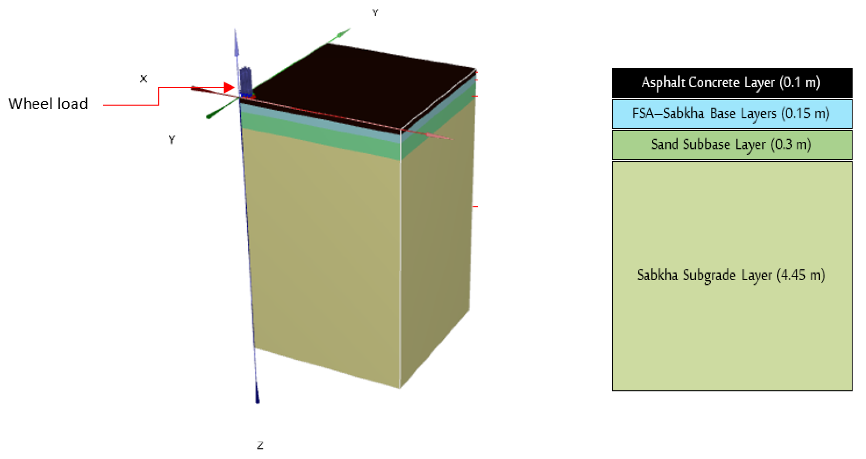
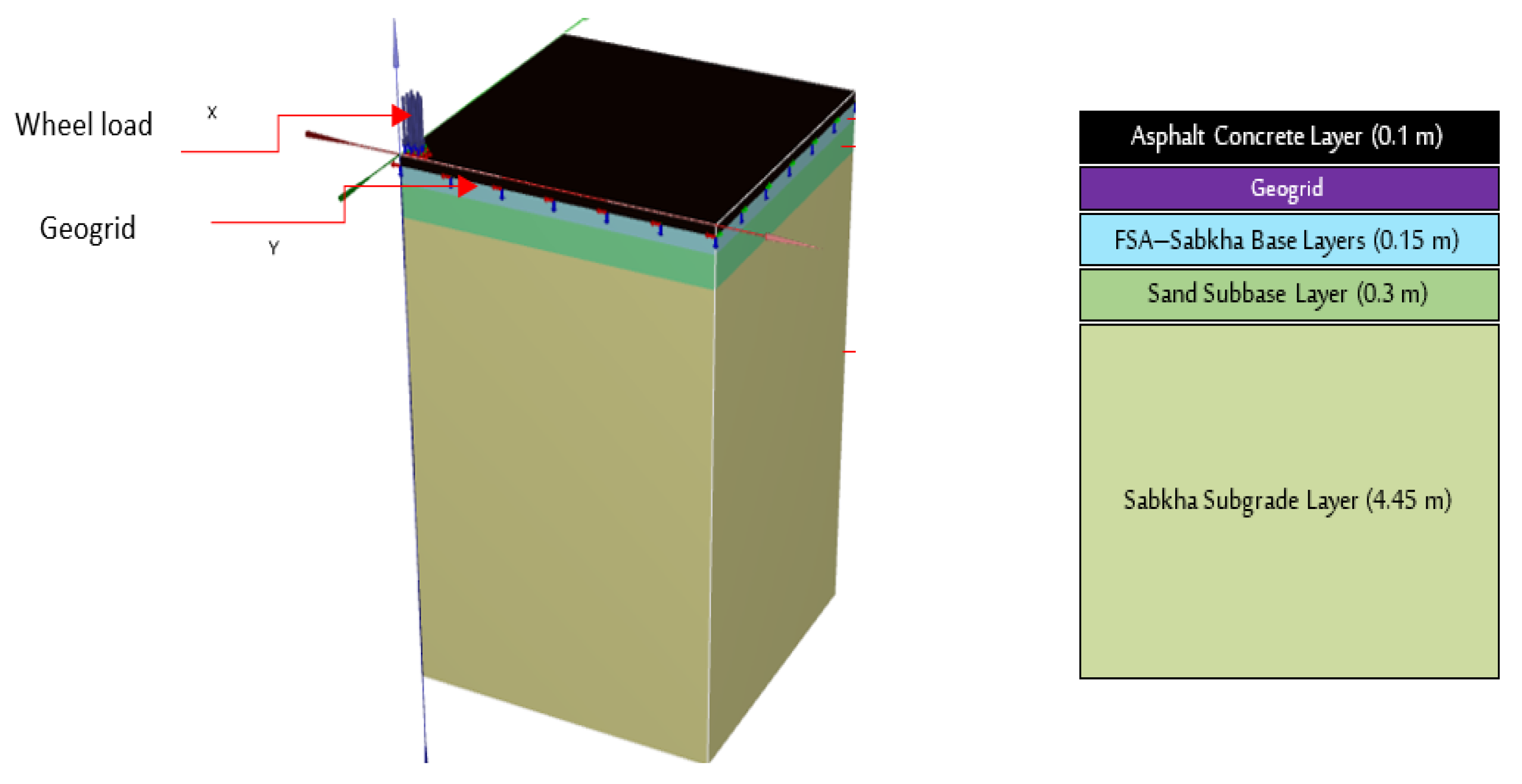
2.2. Loading, Boundary Conditions, and Meshing

Many factors affect the design of a flexible pavement system. These factors can be categorized into four groups: traffic and loading, structural models, material characterizations, and environmental conditions. Traffic is considered the greatest significant factor in designing a pavement structure. Tire pressure, wheel load, load movement and repetition, and configuration of axles are all key factors. Heavier vehicles are the main cause of the distress and failure of pavements. The contact area and pressure between the surface of the pavement and the wheel depends on tire pressure. The real shape of the contact area is elliptical; however, scientists consider it as circular for the purpose of analysis simplification. The radius of this circular area is defined based on tire contact pressure and wheel load. To model the dual wheel exercised load on the pavement surface, a pressure of contact approximately 550 kPa was utilized in the modeling, and it is a repeated load, as shown in Figure 2. The pressure of tire contact on the pavement is equivalent to tire inflation pressure with a circular area of a radius of 200 mm representing the tire imprint. The tire wall stiffening’s effect was ignored. The boundary conditions adopted in the modeling are such that the model is limited at the bottom, and no movements were considered in the orientations vertical to the symmetric axes, i.e., roller support.
Plaxis 3D can generate the mesh automatically as seen in Figure 6. The mesh of the finite element model was established by utilizing ten-node tetrahedral elements to simulate all layers of pavement. The geogrid reinforcement was simulated using geogrid elements offered by the Plaxis 3D software, consisting of six-node triangular surface elements. The mesh size effect was avoided by using fine mesh analysis for reinforced and unreinforced pavement sections to achieve accurate results. The final target mesh generation created around 54,481 elements and 78,817 nodes in the unreinforced section and 86,619 elements and 122,752 nodes in the reinforced section. In comparison to the used mesh size results, further mesh refining requires greater resources and CPU running times, without any convergence enhancement.

3. Results and Discussion

A parametric investigation was conducted to surmise the influence of the position of a geogrid membrane on the structural behavior of flexible pavement sections with a stabilized Sabkha base layer. Three locations were selected to place the geogrid separately. First, the geogrid was positioned between the surface asphaltic concrete layer and stabilized Sabkha base (FSA–Sabkha) layer. The second location was between the FSA–Sabkha base and sand subbase layers. The last location was on the Sabkha subgrade. Using the Plaxis 3D software, pavement critical responses such as fatigue and rutting strains ( ε t m a x and ε c m a x ) were computed for all reinforced and unreinforced pavement sections. The tensile and compression strains ( ε t m a x and ε c m a x ) were estimated at bottom of the asphaltic concrete and stabilized base layers and the top of the subgrade, respectively. Table 2 presents the predicted responses of all cases.
Based on the presented results, it is seen that fatigue strains (horizontal strain) at the bottom of the asphaltic concrete layer were reduced by 5.94% when the pavement was reinforced with a geogrid located at the interface of bituminous concrete and a stabilized Sabkha base layer. However, a decrease of approximately 27.68% in fatigue strains was attained once the geogrid was located at the bottom of the stabilized Sabkha base layer while a decrease of 32.71% was achieved when placed on the subgrade. It is clear that when the geogrid reinforcement is placed at the bottom of the stabilized base layer, it substantially helps reduce the horizontal fatigue tensile strain developed at the interface. This could be attributed to the high modulus of the stabilized Sabkha base layer, thus, resulting in high layer stiffness, making it behave similar to the top asphaltic layer in fatigue resistance.
On the other hand, no significant reduction in the rutting strains (vertical strains) was observed in all cases of pavement geogrid reinforcement. The maximum reduction was noticed when the geogrid was put on the Sabkha subgrade and was about 13.2%. Similarly, marginal differences in total vertical displacement under the load were found between unreinforced pavement and geogrid-reinforced sections. Maximum reduction was at about 14.2% when the geogrid reinforcement was located on the subgrade. This could be attributed to the fact that geogrids are tensile-resistant materials and are not used mainly to reduce vertical displacement in most cases [34,46,47]. However, from Table 2, it is noticed that the maximum reduction in fatigue, rutting strains, and vertical displacement values are obtained when the geogrid is placed on the subgrade, concluding that this is the best location for the geogrid. Figure 7 shows the FE results for the specimen on which the geogrid is placed on the subgrade.
The analysis outcomes of this research are quantitative in comparison with the investigation outcomes of the reported literature. It was seen that an insignificant reduction in fatigue strains was obtained (2.1%) in the case of positioning the geogrid between the asphaltic concrete layer and stabilized base. However, there was a fairly good matching in the reduction (21.1%) noticed in the horizontal strains (fatigue strains) obtained in this research once the geogrid reinforcement was positioned at the interface of the stabilized base and subbase course layers, the outcomes stated previously by Dondi [48] and Pandey et al. [34] (20% and 22.35%, respectively). These remarkable results may be attributed, as mentioned beforehand, to the stabilization-induced high stiffness of the base course layer. Al-Azzawi [33] reported the same trend even though the user base course layer was not stabilized. For rutting strains (vertical strains), the maximum reduction occurred when the geogrid was placed at the subgrade layer. This trend was stated and documented in literature by many investigators [26,34,38,39,49]. Alkaissi and Al-Soud [50] reported that the implementation of the geogrid layer led to decreases in permanent deformation on the subgrade and surface layers by approximately 44% and 35.5%, respectively. Furthermore, vertical strains and stresses were reduced by 50% and 12%, respectively. Alharbi et al. [14] observed that there was a noticeable reduction in the produced vertical compressive stresses under the loading area that the geogrid resists. Amena [51] evaluated various models to establish the safety factors and tensile strength of geogrid necessary to stabilize the embankment. The author reported that the inclusion of geogrid reinforcement significantly raises the safety factor for embankments. Sadiq et al. [52] also reported that the geogrid layer serves as a reinforcing material to lessen rutting in the road by decreasing displacement.

4. Impact of Geogrid Reinforcement on Fatigue and Rutting Life Intervals

Based on field examinations and evaluations of the pavement surface conditions of most roads, it was found that fatigue cracking and rutting are considered the most significant distresses of a pavement’s structure. The load repetition applied by the moving wheel leads to the initiation of cracking in the asphaltic concrete layer, called fatigue cracking. However, the accumulation of plastic strains in all pavement layers under the repeated loads is called rutting that formed along the wheel path. It is known that horizontal tensile strains ( ε t m a x ) evolved at the bottom of the asphaltic concrete layer are considered as an index for fatigue distress, whereas vertical compression strains ( ε c m a x ) are considered as an indicator for rutting distress. Many models related tensile strains and load repetitions number with fatigue failure and between load repetitions number and compressive strains for rutting failure [53,54,55]. In this study, the failure criterion for fatigue cracking and rutting was evaluated based on the correlations established by the asphalt institute (Equations (1) and (2)) as follows:
For fatigue,
N f = 0.0796 ( ε t ) 3.291 ( E ) 0.854
where N f = Load applications number till failure,   ε t = Horizontal tensile strains at the bottom of the asphaltic layer, and E = Modulus of elasticity of asphaltic concrete layer.
For permanent deformation (rutting),
N f = 1.365 × 10 9 ( ε c ) 4.477
where N f = Load applications number till failure, and ε c = Vertical compressive strains at the bottom of the asphaltic layer.
It is well known that damage to pavement structure occurs and develops rapidly under heavier loads. To address the influence of geogrid reinforcement on rutting and fatigue strains, higher axle loads were applied through the 3D finite element model, built using the Plaxis 3D software, for the unreinforced pavement structure section and geogrid-reinforced pavement structure in which the geogrid membrane was positioned at the Sabkha subgrade. The developed horizontal strains, i.e., fatigue strains, at the bottom of the asphaltic concrete layer, and the vertical compressive strains, i.e., rutting strains, at the top of the Sabkha subgrade, were used in Equations (1) and (2) to deduce the fatigue and rutting life intervals.
The damage ( D i ) produced by each application of a single axle load can be determined by Equation (3):
D i = 1 / N i
where D i is known as the accumulative damage and N i the lowest number of load applications caused either by rutting or fatigue failure, as given by Equations (1) and (2). The whole number of load applications ( N f ) that are accepted over the pavement service life could be found when the entire accumulative damage ( D i ) amounts to one. Figure 8 presents the determined fatigue damage ratios against axle loads for unreinforced and geogrid-reinforced pavement structures. A noticeable decrease in fatigue damage was observed in pavements with geogrid reinforcement ranging from 33% to 55% for the various axle loads applied. On the other hand, no significant differences in the rutting damage ratio were found, per Figure 9; a reduction in the rutting damage ratio, ranging from 14% to 30%, was noticed for the various applied axle loads. From the results, geogrid is a tensile-resistant material that can mitigate fatigue cracking to a certain degree, and its effects in reducing rutting distress are marginal. The analysis’s findings in the study by Qadir et al. [56] demonstrate that using flexible geogrid increases rutting resistance. Jayalath et al. [57] observed that composite geogrid reinforcement is efficient at reducing vertical stresses, as well as subgrade deformations, on weak subgrades in thinner granular pavements.

5. Comparing Plaxis 3D Outcomes with Laboratory Test Results

To validate the simulation results of Plaxis 3D, simulated pavement layers were constructed in the laboratory and then tested using a Wessex wheel-tracking machine. The geogrid was placed on the Sabkha subgrade at the optimum location, based on the finite element simulation outcomes discussed beforehand. Two sample models were prepared with lengths of 50 cm and widths of 25 cm. Figure 10 shows the setup of samples on the Wessex wheel tracker. The test was applied under a wheel load of 552 kPa (as used in the Plaxis 3D simulation), by putting sets of weights on each wheel of the tracker (see Figure 10). Each wheel weighed 18 kg. A static weight of steel plates provides the necessary contact stress (4.5 kg each). In other words, we needed to put eight steel plates (4.5 kg each) on each wheel, thus, the weight of these plates combined with the wheel’s weight, divided by the contact area (1000 mm2), gave the required load for testing (552 kPa). The deformation of pavement samples with the number of wheel passes is recorded through the wheel tracker deformation-recording unit. Figure 11 demonstrates the comparison of the vertical deformation resulting from the finite element analysis using the Plaxis 3D software and the laboratory wheel tracking test results. Based on the figure, a satisfactory consistency between the results was clearly shown. This leads to the conclusion that using Plaxis 3D in the FEM can help predict the performance and deformation of a pavement section with stabilized Sabkha soil as a base layer.

6. Conclusions

A series of 3D finite element models were constructed to estimate the merits of incorporating a layer of geogrid inside pavement structures containing a base layer of marginal problematic Sabkha soil stabilized with Foamed Sulfur Asphalt (FSA). The simulations were performed under a parametric investigation to figure out the positive effects of an FSA–Sabkha base layer and geogrid reinforcement on the rutting and fatigue strains criteria. Based on the outcomes of the simulations, the conclusions are as follows:
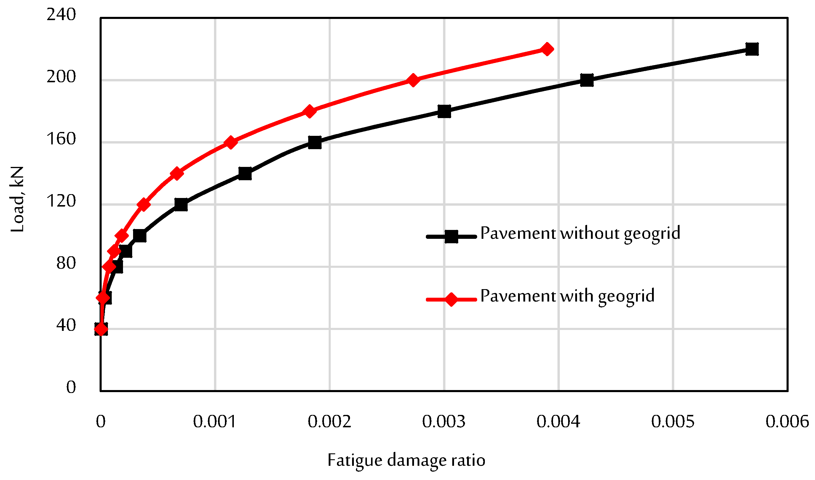
  • When the geogrid was positioned at the Sabkha subgrade layer, it led to the maximum reduction in horizontal tensile strains, up to 32.71%. Thus, geogrid reinforcement showed good potential for decreasing fatigue strains in the pavement structure.
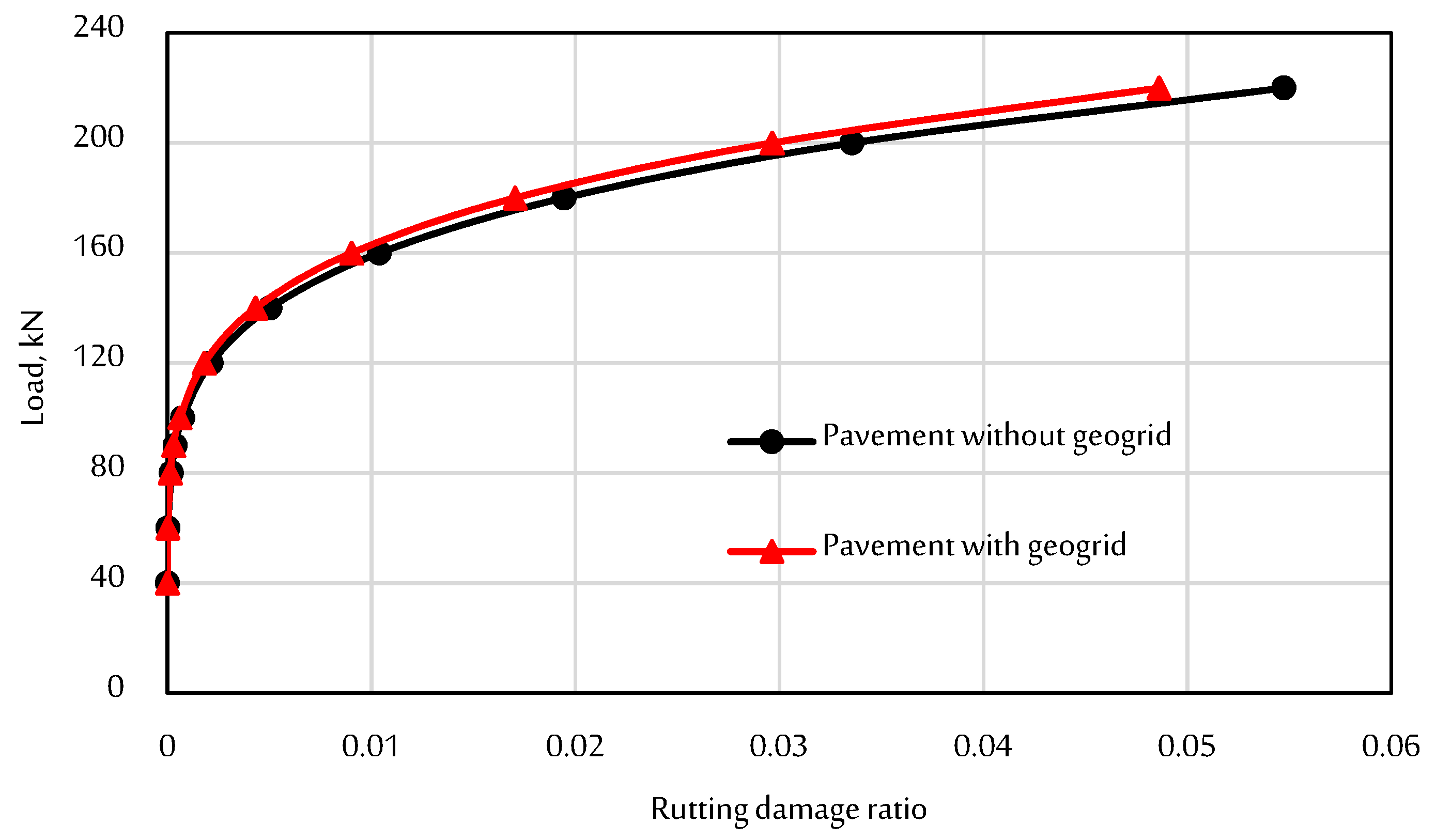
  • No significant differences in the vertical strains were found between reinforced and geogrid-reinforced pavements. The highest reduction was about 13.2%. Similarly, the maximum reduction for vertical displacement was about 14.2%.
  • Geogrid reinforcement decreased the fatigue damage ratio significantly (33% to 55%), while the reduction in rutting damage ratio was a little bit lower (14% to 30%). However, its effect in reducing vertical displacement was marginal.
  • Positioning a geogrid on the subgrade leads to a higher reduction in fatigue, rutting strains, and vertical displacement.
  • Geogrid reinforcement enhanced the performance of the pavement structures consisting of stabilized Sabkha with a foamed sulfur asphalt base layer, which was resting at the marginal problematic Sabkha subgrade and was usable for low-to-moderate traffic volume roads.
  • The use of FE simulations with the Plaxis 3D software is a powerful and reliable tool for predicting the performance of Sabkha soil in pavement structure materials under traffic loading, as evidenced by extremely satisfactory results when compared to laboratory experimental tests.

Funding

This research was funded by the Deanship of Scientific Research at Najran University under the National Research Priorities funding program (NU/NRP/SERC/11/33).

Institutional Review Board Statement

Not applicable.

Informed Consent Statement

Not applicable.

Data Availability Statement

Data are contained within the article.

Acknowledgments

The author is thankful to the Deanship of Scientific Research at Najran University for funding this work under the National Research Priorities funding program (NU/NRP/SERC/11/33).

Conflicts of Interest

The author declares that he has no conflict of interest to report regarding the present study.

References

  1. Akili, W. Salt encrusted desert flats (sabkha): Problems, challenges and potential solutions. In Unsaturated Soils 2006; American Society of Civil Engineers: Reston, VA, USA, 2006; pp. 391–402. [Google Scholar] [CrossRef]
  2. Abdullah, G.M.; Wahhab, H.I.A.-A.J.C.; Materials, B. Evaluation of foamed sulfur asphalt stabilized soils for road applications. Constr. Build. Mater. 2015, 88, 149–158. [Google Scholar] [CrossRef]
  3. Al-Homidy, A.A.; Dahim, M.H.; El Aal, A.K.A. Improvement of geotechnical properties of sabkha soil utilizing cement kiln dust. J. Rock Mech. Geotech. Eng. 2017, 9, 749–760. [Google Scholar] [CrossRef]
  4. Abdullah, G.M.; Al-Abdul Wahhab, H.I.J.R.M.; Design, P. Stabilisation of soils with emulsified sulphur asphalt for road applications. J. Rock Mech. Geotech. Eng. 2019, 20, 1228–1242. [Google Scholar] [CrossRef]
  5. Abdullah, G.M.S. Modeling the Behavior of Sulfur Modified Foamed and Emulsified Asphalt Soils Mixes for Local Road Applications. Ph.D. Thesis, King Fahd University of Petroleum and Minerals, Dhahran, Saudi Arabia, 2014. [Google Scholar]
  6. Abdullah, G.M.; El Aal, A.A. Assessment of the reuse of COVID-19 healthy personal protective materials in enhancing geotechnical properties of Najran’s soil for road construction: Numerical and experimental study. J. Clean Prod. 2021, 320, 128772. [Google Scholar] [CrossRef]
  7. Al-Amoudi, O.S.B.; Abduljauwad, S.N.; El-Naggar, Z.R.J.E.G. Response of sabkha to laboratory tests: A case study. Eng. Geol. 1992, 33, 111–125. [Google Scholar] [CrossRef]
  8. Abduljauwad, S.; Al-Amoudi, O.J.G. Geotechnical behaviour of saline sabkha soils. Geotechnique 1995, 45, 425–445. [Google Scholar] [CrossRef]
  9. Asi, I.; Siddiqui, Z.; Al-Abdul Wahhab, H.; Khan, M. Stabilization of sabkha soil for road bases using foamed asphalt technology. In Proceedings of the Fifth Saudi Engineering Conference, Makkah, Saudi Arabia, 1–4 March 1999. [Google Scholar]
  10. Asi, I.M.; Wahhab, H.A.-A.; Al-Amoudi, O.B.; Khan, M.I.; Siddiqi, Z. Stabilization of dune sand using foamed asphalt. Geotech. Test. J. 2002, 25, 168–176. [Google Scholar]
  11. Abdullah, G.M.J.G.; Engineering, G. Pavement thickness design charts derived from rut depth models developed for foamed and emulsified sulfur asphalt soil mixes. Geotech. Geol. Eng. 2020, 38, 3053–3065. [Google Scholar] [CrossRef]
  12. Kazmi, Z.A. Application of date palm ash to improve strength characteristics of sabkha soil. IOP Conf. Ser. Mater. Sci. Eng. 2020, 958, 012007. [Google Scholar] [CrossRef]
  13. Raja, M.N.A.; Shukla, S.K. Predicting the settlement of geosynthetic-reinforced soil foundations using evolutionary artificial intelligence technique. Geotext. Geomembr. 2021, 49, 1280–1293. [Google Scholar] [CrossRef]
  14. Alharbi, F.; Almoshaigeh, A.; Almoshaogeh, M.; Elragi, A.; Elkholy, S.J.E. Effect of Geo-Grid Depth in Roads Cross-Section on Reducing Pavement Rutting. Eng 2022, 3, 1–8. [Google Scholar] [CrossRef]
  15. Krishna, U.S.R.; Ch, N.S.K. Analytical modelling of ultra-thin white topping cement concrete overlay on bituminous concrete pavement using ANSYS. World J. Eng. 2022; ahead-of-print. [Google Scholar] [CrossRef]
  16. Abdullah, G.M. 3D finite element modeling to predict the foamed sulfur asphalt marl soil mixes rutting behavior. Ain Shams Eng. J. 2019, 10, 661–668. [Google Scholar] [CrossRef]
  17. Peng, J.; Zhang, J.; Li, J.; Yao, Y.; Zhang, A. Modeling humidity and stress-dependent subgrade soils in flexible pavements. Comput. Geotech. 2020, 120, 103413. [Google Scholar] [CrossRef]
  18. Mousavi, S.H.; Gabr, M.A.; Borden, R.H. Optimum location of geogrid reinforcement in unpaved road. Can. Geotech. J. 2017, 54, 1047–1054. [Google Scholar] [CrossRef]
  19. Abdullah, G.M. Using Plaxis 2D finite element modeling to assess bearing capacity of Sultana’s soil in Najran Region, Kingdom of Saudi Arabia. Mater. Today Proc. 2022, 49, 2679–2687. [Google Scholar] [CrossRef]
  20. Djellali, A.; Sarker, D.; Saghafi, B. Experimental and numerical prediction of airport pavement over expansive subgrade stabilized by asphalt layers. Arab. J. Geosci. 2022, 15, 1503. [Google Scholar] [CrossRef]
  21. Mudiyono, R. Evaluating the Road Construction Feasibility Performance of the Rigid Pavement in the Flood-Prone Area: A Case Study of Indonesia. IOP Conf. Ser. Earth Environ. Sci. 2022, 971, 012007. [Google Scholar] [CrossRef]
  22. Berg, R.R.; Christopher, B.R.; Perkins, S. Geosynthetic reinforcement of the aggregate base course of flexible pavement structures. In Geosynthetic Materials Association; Ryan R. Berg & Associates, Inc.: Roseville, MN, USA, 2000; Volume 130. [Google Scholar]
  23. Perkins, S.W. Mechanistic-Empirical Modeling and Design Model Development for Geosynthetic Reinforced Flexible Pavements; Montana. Dept. of Transportation, Research Section: Helena, Montana, 2001. [Google Scholar] [CrossRef]
  24. Perkins, S. Evaluation of Geosynthetic Reinforced Flexible Pavement Systems Using Two Pavement Test Facilities; Federal Highway Administration: Washington, DC, USA, 2002. [Google Scholar] [CrossRef]
  25. Howard, I.L.; Warren, K.A. Finite-element modeling of instrumented flexible pavements under stationary transient loading. J. Transp. Eng. 2009, 135, 53–61. [Google Scholar] [CrossRef]
  26. Wathugala, G.W.; Huang, B.; Pal, S. Numerical simulation of geosynthetic-reinforced flexible pavements. Transp. Res. Rec. J. Transp. Res. Board 1996, 1534, 58–65. [Google Scholar] [CrossRef]
  27. Valašková, V.; Vlček, J.; Papán, D. Determination of the Small-Scale Physical Model Parameters of Pavement Structure. Sustainability 2020, 12, 9637. [Google Scholar] [CrossRef]
  28. Ling, J.; Wei, F.; Zhao, H.; Tian, Y.; Han, B.J.C.; Materials, B. Analysis of airfield composite pavement responses using full-scale accelerated pavement testing and finite element method. Constr. Build. Mater. 2019, 212, 596–606. [Google Scholar] [CrossRef]
  29. Liu, Z.; Gu, X.; Ren, H.; Zhou, Z.; Wang, X.; Tang, S. Analysis of the dynamic responses of asphalt pavement based on full-scale accelerated testing and finite element simulation. Constr. Build. Mater. 2022, 325, 126429. [Google Scholar] [CrossRef]
  30. Liu, Z.; Gu, X.; Ren, H.; Wang, X.; Dong, Q. Three-dimensional finite element analysis for structural parameters of asphalt pavement: A combined laboratory and field accelerated testing approach. Case Stud. Constr. Mater. 2022, 17, e01221. [Google Scholar] [CrossRef]
  31. Ling, H.I.; Liu, H. Finite element studies of asphalt concrete pavement reinforced with geogrid. J. Eng. Mech. 2003, 129, 801–811. [Google Scholar] [CrossRef]
  32. Sukumaran, B.; Willis, M.; Chamala, N. Three dimensional finite element modeling of flexible pavements. In Advances in Pavement Engineering; American Society of Civil Engineers: Reston, VA, USA, 2005; pp. 1–12. [Google Scholar] [CrossRef]
  33. Al-Azzawi, A.A. Finite element analysis of flexible pavements strengthed with geogrid. ARPN J. Eng. Appl. Sci. 2012, 7, 1295–1299. [Google Scholar]
  34. Pandey, S.; Rao, K.; Tiwari, D. Effect of geogrid reinforcement on critical responses of bituminous pavements. In Proceedings of the ARRB Conference, 25th, 2012, Perth, Western Australia, Australia, 23–26 September 2012. [Google Scholar]
  35. Sinha, A.K.; Chandra, S.; Kumar, P. Finite element analysis of flexible pavement with different subbase materials. Indian Highw. 2014, 42, 57–66. [Google Scholar]
  36. Tapase, A.B.; Ranadive, M. Performance evaluation of flexible pavement using the finite element method. In Geo-China 2016; American Society of Civil Engineers: Reston, VA, USA, 2016; pp. 9–17. [Google Scholar] [CrossRef]
  37. Al-Mehthel, M.; Al-Idi, S.H.; Wahhab, H.I.A.-A.; Hussein, I.A. Foamed Sulfur Asphalts for Pavement Recycling and Soil Stabilization. U.S. Patent 9,346,956, 24 May 2016. [Google Scholar]
  38. Moayedi, H.; Kazemian, S.; Prasad, A.; Huat, B.B.K. Effect of geogrid reinforcement location in paved road improvement. EJGE 2009, 14, 1–11. [Google Scholar]
  39. Sina, K.; Maassoumeh, B.; Arun, P.; Hossein, M.; Bujang, B.H.K. Reinforced pavement above trench under urban traffic load: Case study and finite element (FE) analysis. Sci. Res. Essays 2010, 5, 3313–3329. [Google Scholar]
  40. Alex, A. Characterization of Unbound Granular Layers in Flexible Pavements; Report No. ICAR/502-3; Texas Transportation Institute: Bryan, TX, USA, 2000. [Google Scholar]
  41. Brinkgreve, R.; Engin, E.; Swolfs, W. PLAXIS 3D 2020 User Manual; Plaxis bv: Delft, The Netherlands, 2020. [Google Scholar]
  42. Schanz, T.; Vermeer, P.; Bonnier, P.G. The hardening soil model: Formulation and verification. In Beyond 2000 in Computational Geotechnics; Routledge: Abingdon, UK, 2019; pp. 281–296. [Google Scholar] [CrossRef]
  43. Wu, K.; Ma, J.; Chuai, M.; Li, C.-H.; Chen, Y.; Lv, F. Numerical simulation of the near-fault spontaneous rupture and its influence on dynamic soil-structure interaction. Structures 2022, 38, 808–819. [Google Scholar] [CrossRef]
  44. Bolton, M.J.G. The strength and dilatancy of sands. Can. Geotech. J. 1986, 36, 65–78. [Google Scholar] [CrossRef]
  45. Mirmoradi, S.; Ehrlich, M. Modeling of the compaction-induced stress on reinforced soil walls. Geotext. Geomembr. 2015, 43, 82–88. [Google Scholar] [CrossRef]
  46. Ibrahim, E.; El-Badawy, S.; Ibrahim, M.; Gabr, A.; Azam, A. Effect of geogrid reinforcement on flexible pavements. Innov. Infrastruct. Solut. 2017, 2, 54. [Google Scholar] [CrossRef]
  47. Majedi, P.; Ghalehjough, B.K.; Akbulut, S.; Çelik, S. Effect of Reinforcement on stability and Settlement of Embankment: A finite element analysis of different kinds of reinforcing and construction conditions. Eur. J. Adv. Eng. Technol. 2017, 4, 759–764. [Google Scholar]
  48. Dondi, G. Three-dimensional finite element analysis of a reinforced paved road. In Proceedings of the fifth International Conference on Geotextiles, Geomembranes and Related Products, Singapore, 5–9 September 1994; pp. 95–100. [Google Scholar]
  49. Saad, B.; Mitri, H.; Poorooshasb, H. 3D FE analysis of flexible pavement with geosynthetic reinforcement. J. Transp. Eng. 2006, 132, 402–415. [Google Scholar] [CrossRef]
  50. Alkaissi, Z.A.; Al-Soud, M.S. Effect of Geogrid Reinforcement on Behavior of Unpaved Roads. IOP Conf. Ser. Earth Environ. Sci. 2021, 856, 012007. [Google Scholar] [CrossRef]
  51. Amena, S. Analysis of the Stability of Reinforced Plastic Waste Treated Clay as Embankment Fill on Soft Soils. Adv. Civ. Eng. 2022, 2022, 1831970. [Google Scholar] [CrossRef]
  52. Sadiq, N.; Hilal, M.M.; Fattah, M.Y. Analysis of Asphalt Geogrid Reinforced Pavement Rutting by Finite Element Method. IOP Conf. Ser. Earth Environ. Sci. 2022, 961, 012049. [Google Scholar] [CrossRef]
  53. Heukelom, W.; Klomp, A. Dynamic testing as a means of controlling pavements during and after construction. In Proceedings of the International Conference on the Structural Design of Asphalt PavementsUniversity of Michigan, Ann Arbor, MI, USA, 20–24 August 1962. [Google Scholar]
  54. Asphalt-Institute. Research and Development of the Asphalt Institute’s Thickness Design Manual (Ms-1), 9th ed.; Asphalt Institute: Lexington, KY, USA, 1982. [Google Scholar]
  55. Finn, F.; Saraf, C.; Kulkarni, R.; Nair, K.; Smith, W.; Abdullah, A. Development of Pavement Structural Subsystems; Transportation Research Board: Washington, DC, USA, 1986. [Google Scholar]
  56. Qadir, A.; Gazder, U.; Choudhary, K.-U. Statistical analysis for comparing and predicting rutting resistance of asphalt pavements with rigid and flexible geogrid layers. Constr. Build. Mater. 2021, 302, 124136. [Google Scholar] [CrossRef]
  57. Jayalath, C.; Gallage, C.; Wimalasena, K.; Lee, J.; Ramanujam, J. Performance of composite geogrid reinforced unpaved pavements under cyclic loading. Constr. Build. Mater. 2021, 304, 124570. [Google Scholar] [CrossRef]
Figure 1. Distribution of Sabkha soil in the Kingdom of Saudi Arabia [7,8].
Sustainability 15 02595 g001
Figure 2. Modeling of pavement section without reinforcement in Plaxis 3D software.
Sustainability 15 02595 g002
Figure 3. FE modeling of a reinforced pavement structure at the top of the FSA–Sabkha base layer in Plaxis 3D software.
Sustainability 15 02595 g003
Figure 4. FE modeling of a reinforced pavement structure at the bottom of FSA–Sabkha base layer in Plaxis 3D software.
Sustainability 15 02595 g004
Figure 5. The Mohr–Coulomb’s material model: (a) Yield surface; (b) E 0 and E 50 definitions; (c) Failure model [41].
Sustainability 15 02595 g005
Figure 6. The final target mesh used in this study.
Sustainability 15 02595 g006
Figure 7. The FE results of a reinforced pavement structure at the top of subgrade: (a) Deformed shape; (b) Total displacement; (c) Tensile strains; (d) Compressive strains.
Sustainability 15 02595 g007
Figure 8. Fatigue damage ratio in unreinforced and reinforced pavement (geogrid is positioned on the Sabkha subgrade).
Sustainability 15 02595 g008
Figure 9. Rutting damage ratio in unreinforced and reinforced pavement (geogrid is positioned on the Sabkha subgrade).
Sustainability 15 02595 g009
Figure 10. Wheel tracker machine.
Sustainability 15 02595 g010
Figure 11. Comparisons of the FEM and laboratory test results.
Sustainability 15 02595 g011
Table 1. Material parameters for the finite element modeling (reported by Abdullah and Al-Abdul Wahhab [2]).
ParameterAsphaltic ConcreteStabilized Base (FSA–Sabkha)Subbase
(Sand)
Subgrade
(Sabkha)
Geogrid
Thickness (mm)1001503004450-
Unsaturated Unit Weight, γ u n s a t (KN/m3)20201715.5-
Saturated Unit Weight, γ s a t (KN/m3)-211817.5-
Material ModelLinear elasticHardening soilHardening soilHardening soil-
Drainage Typenon-porousDrainedDrainedDrained-
E 50 ref (KPa)-8.5 × 10530,0006000-
E o e d ref (KPa)-8.5 × 10530,0006000-
E u r ref (KPa)-2550 × 10390,00018,000-
Power in Stiffness Laws, m -0.50.50.5-
Unloading–Reloading Poisson’s Ratio, ν -0.20.20.2-
Cohesion, c (KN/m2)-1511-
Angle of Friction, (°)-353534-
Angle of Dilatancy, ψ (°)-554-
Interface Reduction Factor, R i n t e r 1111-
Axial Stiffness, E A (KN/m)----960
Table 2. Fatigue, rutting strains, and total displacement predicted through the finite element model.
Geogrid Location ε t m a x (×10−3)Relative Variation ε c m a x (×10−3) Relative VariationTotal Displacement |u| (×10−3) mRelative Variation
Unreinforced pavement3.299-1.572-6.653-
Geogrid at the top of FSA–Sabkha base.3.103−5.9%1.542−1.9%6.354−4.5%
Geogrid at the bottom of FSA–Sabkha base (Top of subbase)2.386−27.7%1.456−7.4%6.045−9.1%
Geogrid at the top of subgrade 2.262−31.4%1.400−10.9%5.718−14.1%
Disclaimer/Publisher’s Note: The statements, opinions and data contained in all publications are solely those of the individual author(s) and contributor(s) and not of MDPI and/or the editor(s). MDPI and/or the editor(s) disclaim responsibility for any injury to people or property resulting from any ideas, methods, instructions or products referred to in the content.

