1. Introduction
Geothermal energy is a clean and renewable energy source that can be developed for power generation and for direct use, such as space heating. Hot dry rock (HDR) resources denote high-temperature geothermal energy occurring in crystalline rock with low permeability and porosity. The total HDR resources within a 10 km depth all over the world amounts to about 40–400 M EJ (1EJ = 10
18J), approximately 100–1000 times the quantity of fossil fuel energy [
1]. In the past five years, the government of China has been actively investing in the exploration of HDR resources. Many potential HDR targets in China have been found, including the Songliao Basin, southern Hainan, Wendeng, Datong, Zhangzhou, Gonghe-Guide basin and Subei Basin [
2]. In 2020, the government of China announced that China’s carbon emissions will peak by 2030, and they will strive to achieve carbon neutrality by 2060. Large-scale non-carbon energy sources are urgently needed to improve China’s energy structure. Therefore, HDR geothermal energy has attracted the attention of the government and researchers because of its huge reserves and low-carbon emissions.
Economical quantities of geothermal fluids cannot be obtained directly from HDR reservoirs due to their naturally low permeability. Enhanced geothermal systems (EGS), including reservoir stimulation and heat mining technology, can be adopted to extract the thermal energy stored in the HDR. Since the 1970s, numerous EGS projects have experimented with enhancing permeability at both existing and new geothermal sites. Pollack et al. reviewed and described challenges experienced in EGS projects, based on observations from 64 EGS sites [
3]. Six sites ceased operations due to seismicity concerns. Drilling and plant operation issues, such as stuck drill strings and well collapses, delayed or terminated at least 24 EGS projects. At least 18 sites faced challenges in reservoir creation and circulation. The inability to raise financing either initially or in later project phases has been a major block for many EGS projects. While EGS sites have often encountered difficulties, at least 29 of the projects, including in-field and green field projects, continue to operate and generate electricity at an increasing rate.
Lessons learned from these EGS projects show that there are many factors affecting the final heat production of an EGS reservoir during the whole operational process. The stress state and rock properties of the target reservoir have an important influence on the geometry and permeability of the created reservoir [
4]. When selecting the target reservoir for an EGS, the ideal target formation is one with a high temperature and well-developed natural fractures. The temperature factor is easy to determine, just by the selection of a high-temperature layer. However, better natural fracture development does not necessarily mean better productivity. This depends on fracturing and heat transfer effects. The effect of reservoir stimulation determines the amount of thermal energy that can then be extracted. During the heat-extraction stage, the well layout pattern and operational parameters affect the final productivity significantly. Therefore, the influence of reservoir characteristics and the stimulation scheme on heat-production performance from EGS should be investigated to optimize the heat-mining strategy.
Hydraulic shear stimulation in naturally fractured formation has been proven to be effective for power generation and has been used widely in EGS projects [
5,
6,
7]. The fracture network is formed through the self-support of staggered natural fractures after fracturing [
8,
9]. For the stimulated EGS reservoir, there are mainly two methods for characterizing the fracture network for evaluating the heat-production performance: the equivalent continuous porous medium and real discrete fracture network [
10,
11]. The equivalent continuous porous method approximates the discrete fracture system as continuous porous media. Variants of this approach are the equivalent porous media method (EPM), the effective continuum method (ECM), the double-porosity method (DPM), and the multiple interacting continua (MINC) method. EPM is mainly used to model densely fractured reservoirs, where fracture density is high and fracture spacing is small, with the average fracture spacing less than 2~3 m, for example [
5,
10]. When the average fracture spacing is small, the EPM can attain good simulation results, while for large average fracture spacings, the DPM method gives better results [
12]. The MINC method yields intermediate behaviors between a porous medium model and a single fracture model [
13]. Suzuki et al. [
14] conducted fractional diffusion modeling of heat transfer in porous and fractured media. They concluded that the porous media model matched the results of the MINC model for smaller fracture spacing (<5 m), while the single-fracture model agreed with the results of the MINC model for larger fracture spacing (>20 m). Fracture networks are the dominant channels for water to transfer mass and heat in an HDR reservoir. A detailed description of the fractures is critical for numerical simulations. The discrete fracture network (DFN) model can be used to analyze the fracture orientation, size, spacing and other mechanical properties [
15]. If the data of reservoir fracture distribution are adequate, the DFN model can be adopted.
Geological conditions and the fracturing scheme have a significant influence on fractured HDR reservoirs. Hence, the heat-extraction scheme should be optimized based on the results of the reservoir stimulation. Whether a formation is suitable as an EGS target reservoir is mainly determined by the final productivity performance. During the water circulation stage, the well pattern and operational parameters have important effects on thermal energy production. The main indices for evaluating EGS performance include power generation and flow impedance (or injectivity). The water production rate [
16], production temperature [
17], injection pressure [
18], pump power [
8,
19], and energy efficiency [
18,
20], are also considered by many researchers.
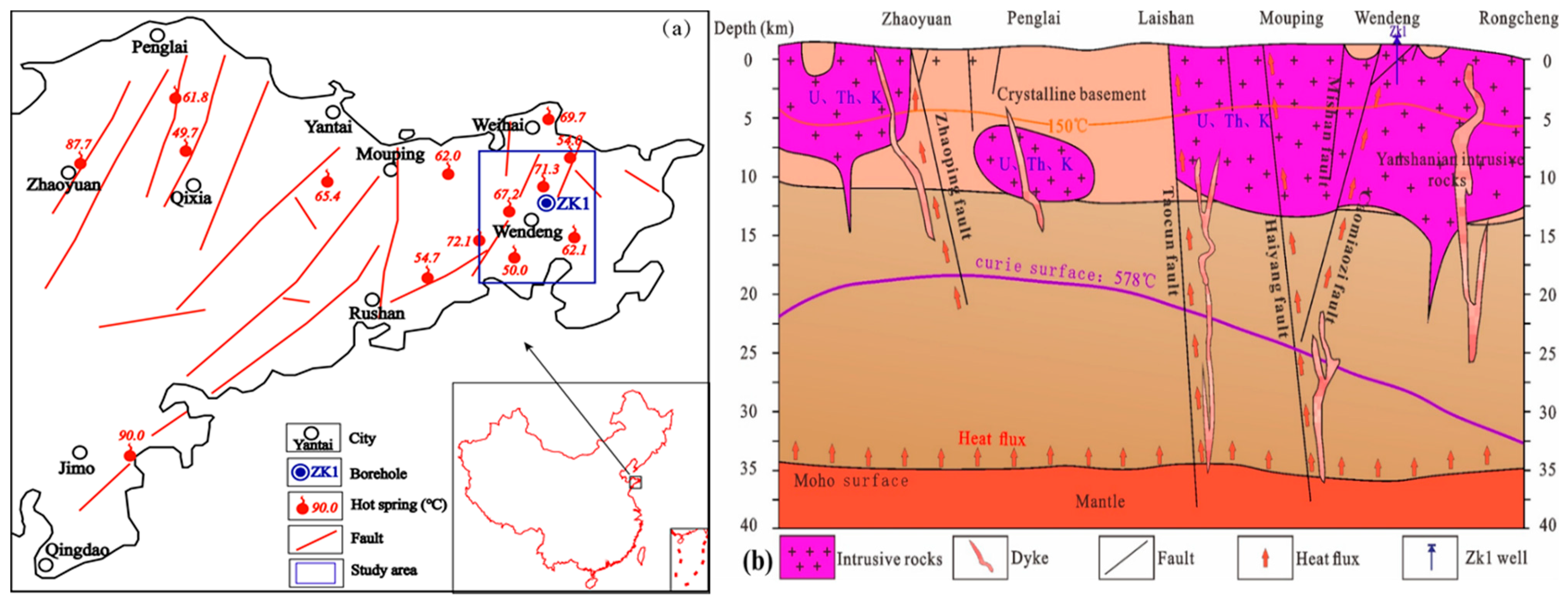
Wendeng geothermal field has been developed for its hydrothermal geothermal resources for many years. This indicates that there exist abundant thermal resources in the underground. Super-thick shallow granites are widely distributed in Wendeng geothermal field. They are largely exposed to the surface without a cap layer, and their thermal structure is different from sedimentary-type geothermal fields. In order to evaluate whether this area has the potential for the development of HDR geothermal resources, Shandong provincial government has carried out a geothermal geological survey, drilling and logging in the Wendeng geothermal field area. The project is still in the feasibility study stage. The next plan is to select the appropriate reservoir for reservoir stimulation. In this study, we carried out field tests, laboratory tests and numerical simulations in succession to evaluate its productivity potential as an EGS. The geothermal characteristics and deep rock mechanical properties were identified based on real geological and core data from the borehole ZK1 in Wendeng geothermal field. Then, a numerical model of reservoir hydraulic fracturing based on discrete fracture network was established. Thermal extraction simulations were conducted to assess the long-term productivity of an EGS project based on the fracturing results. These research conclusions could serve as a reference for the development of future HDR geothermal resources in the Wendeng geothermal field.
4. Results
4.1. Geothermal Features
The trend line of temperature changes with depth was obtained (
Figure 4). The average geothermal gradient was 36.8 °C/km between 0 m and 3000 m. The geothermal gradient decreased gradually from 55 °C/km at 200 m to 0 °C/km at 3000 m. Between 0 m and 1100 m, the formation temperature changes were almost linear. The reason is that the lithology is uniform, its thermal conductivity changes little, and there is no cap layer. Below 1100 m, the temperature drops because the well has penetrated along the water-conducting fault, which indicates a possible convection-type geothermal system. This is good for traditional hydrothermal geothermal development, but the temperature is still too low for a HDR reservoir, which require further drilling. Generally, geothermal gradients increase linearly with depth in this super-thick shallow granite area, as long as water-filled faults are not drilled. Therefore, when choosing shallow high-temperature HDR reservoirs in such super-thick granite areas, attention should be paid to avoiding deep fault zones.
The thermal properties of 40 core samples taken at different depths were obtained. Their heat conductivity ranged from 3.02 to 4.82 W/(m·K), with an average value of 3.52 W/(m·K). The average specific heat capacity was 850 J/(kg·K).
At present, the ZK1 well is only drilled to 3000.17 m, and the bottom-hole temperature is about 121.09 °C, which still corresponds to a middle-low temperature geothermal resource. To extract higher quality energy from the HDR resource, the well needs to be drilled deeper in the future. In this study, the formation at depth of 4000 m was initially selected as the potential target reservoir for production analysis. The formation temperature is expected to be about 181 °C at 4000 m if the deep formation belongs to conductive type of geothermal system.
4.2. Stress State
The natural formation is in a triaxial stress state. The size and morphology of hydraulic fractures are greatly affected by the in situ stress. During the process of drilling, the ZK1 well encountered 20 “broken cake” rock layers. “Broken cake” is an indicator of a high level of existing in situ stress. The thinner the cake, the higher the stress.
Table 4 lists a total of five layers with a thickness of “broken cake” layer greater than 7 m. After drilling, the original stress condition is destroyed, leading to the cracking.
Hou proposed that once the in situ stress is large enough, “broken cake” core will occur [
33]. The maximum horizontal principal stress (
σH) can be deduced from the “broken cake” core characteristics according to the following equations
where
t is the thickness of each “broken cake” core (mm);
D is the diameter (mm);
τ0 is the shear strength.
In well ZK1, the thickness of “broken cake” core varies with depths. Taking the layer 2838.98~2872.51 m as an example, the thickness of “broken cake” core is mostly between 12 mm and 18 mm. The known core diameter is 62 mm, and the average shear strength is 24 MPa. Therefore, the calculated value of σH between 2838.98 m and 2872.51 m is 70.0~78.1 MPa.
After analyzing the hydraulic fracturing data from 13 oil wells in Shengli Oilfield in Shandong province [
34], the stress magnitude as function of depth (for 1300 m~3300 m depth) can be summarized as
where
H is the depth (m);
σH is the maximum principal stress (MPa);
σh is the minimum principal stress (MPa). The vertical principal stress (
σv) is often calculated by
σv =
ρgh. Thus, at the depth of 2850 m, the calculated in-situ stress is
σH = 76.1MPa,
σh = 53.2MPa,
σV = 74.1 MPa. It can be seen that the difference of
σH calculated according to Equations (6) and (7) is very small. It shows that horizontal stress plays a dominant role in the study area. Therefore, at the depth of 4000 m, the calculated
σH,
σh and
σV are expected to be 109.4 MPa, 79.6 MPa and 103.9 MPa, respectively.
4.3. Stimulated Reservoir and Well Pattern
Table 5 shows the results for the stimulated fracture network under Case 1. Due to the limitation of stress shielding and the large maximum horizontal principal stress, the reservoir fracture network mainly extends in the horizontal direction.
Horizontal or deviated wells were used in this study. The fracturing well was used as the injection well. The production wells are not fractured and are drilled directly through the boundary of the EGS reservoir (
Figure 5). Due to the low permeability of the boundary zone of the fractures, the internal zone of the fracture network was selected as the simulated EGS reservoir. Based on the fracturing result, the thermal extraction well layout mode was set up as seen in
Figure 6. The size of the EGS reservoir is 1400 m (Length) × 400 m (Width) × 35 m (Height). A triplet well layout mode was considered. It should be noted that the MShale simulator processes fractures into an orthogonal distribution. Thus, the injection and production wells are placed on the main fracture profile to obtain the longest flow path, as shown in
Figure 6b. However, the natural fracture distribution has the characteristics of spatial heterogeneity. Well placement is strongly influenced by the fracture map and has a great impact on the heat productivity [
35]. When more detailed reservoir information is available in the future, the effect of fracture properties should be considered in determining the well placement pattern.
4.4. Heat Production Performance
Figure 7 shows the evolutions of
Tpro and
We at different injection rates (
qinj) over the 20 years. With the increase of injection rate,
Tpro decreases continuously. When the injection rate is 20 kg/s,
Tpro decreases down to 119.8 °C. When the injection rate increases to 70 kg/s,
Tpro drops to 109.6 °C in the 5th year and 85.2 °C in the 20th year, which is 20.2 °C higher than the injection temperature. The higher the injection rate, the higher the
We in the early stages of the project, but the decline rate of
We is fast, and
We is soon lower than that at the low injection rate. For 20 kg/s and 70 kg/s, for example, the two
We curves intersect in the fifth year. Five years later, the
We at 20 kg/s is consistently higher than that at 70 kg/s.
Figure 8 shows the evolutions of
IR and
Pinj at different injection rates (
qinj) over the 20 years. The
IR and
Pinj both increase with the increase of injection rate. During the 20 years of operation, the
IR and
Pinj at 70 kg/s are, respectively, 0.03 MPa/(kg/s)~0.05 MPa/(kg/s) and 38.3 MPa~40.0 MPa.
Figure 9 shows the evolution of
WP and
ηe at different injection rates (
qinj) over the 20 years. As the injection rate increases,
WP increases, and its increment also increases. Since the
We between different injection rates does not change much at the later stage of the project, the efficiency
ηe is greatly different. During the 20-year period, the efficiencies
ηe at 20 kg/s and 70 kg/s are 197.2~44.1 and 57.2~2.1, respectively.
For the stimulated reservoir, because its length and width are both large, the injected fluid has sufficient time to exchange heat with the reservoir. In addition, the fracture network reservoir has good connectivity between fractures, and so even when the injection rate reaches 70 kg/s, the IR and Pinj indicators are still within the engineering allowable range. However, a too large injection rate results in large energy consumption and makes the energy efficiency decrease too fast. Thus, from the point of view of energy efficiency and power generation, an injection rate of 30 kg/s would be more suitable. For the triplet-well mode, the maximum injection rate is 60 kg/s, the power generation over 20-year period is 8.32 MW~1.62 MW, and the energy efficiency ranges from 142.4 to 17.1.
Figure 10 shows the spatial variations of reservoir temperature fields at the plane
z = 100 m when
qinj is 30kg/s during the 20-year period. The cold halo expands fastest on the connection between the injection well and the production well (the axis). Due to better fracture permeability and connectivity, the cold halo has arrived at the production well by year 2.94. Then, the water flow mainly began to extract heat from the reservoirs on both sides of the axis. In the 20th year, the influence range of heat transfer at the side of the EGS reservoir has extended to 650 m at the plane z = 100 m.
5. Discussions
5.1. Influence of Well Pattern on Production Performance
According to
Section 4.3, the size of EGS reservoir under Case 1 is 1400 m (Length) × 400 m (Width) × 35 m (Height). Because the fracture network is long and wide, production wells can be drilled through different areas of the reservoir. Therefore, thermal extraction simulation analysis with a five-spot well layout mode (Case 2) was also considered to investigate the influence of the well-layout mode on heat-transfer performance (
Figure 11).
Figure 12 shows the evolution of
Tpro and
We at different injection rates (
qinj) over the 20 years under Case 2. By comparing
Figure 7 and
Figure 12, it can be seen that the variation trend of
Tpro and
We curves for Case 2 is almost the same as that for Case 1. However, at the same injection rate, the
Tpro and
We curves in Case 2 are both slightly higher than those in Case 1.
Figure 13 shows the evolution of
IR and
Pinj at different injection rates (
qinj) over the 20 years under Case 2. The
IR and
Pinj of Case 2 are both smaller than those in Case 1. For 70 kg/s, as an example, the
IR and
Pinj are respectively 0.02 MPa/(kg/s)~0.03 MPa/(kg/s) and 37.0 MPa~38.2 MPa.
Figure 14 shows the evolution of
WP and
ηe at different injection rates (
qinj) over the 20 years under Case 2. The
WP of Case 2 is smaller than that in Case 1, thus the
ηe of Case 2 is higher than that in Case 1. The reason for the increasing pump consumption over time is that the temperature decreases, resulting in a viscosity increase, and this requires more injection pressure to push the fluid toward the production wells.
Case 2 and Case 1 have the same reservoir, but different well-layout modes. Therefore, the variation trends of each indicator for the two cases are very similar, but the indicator values are different. The pressure indicator is more sensitive to the well-layout mode than the temperature indicator. For Case 2, from the point of view of energy efficiency and power generation, an injection rate of 30 kg/s or 40 kg/s would be more suitable. For the five-spot well mode, and a maximum injection rate between 60 kg/s and 80 kg/s, the power generation over the 20-year period is 8.32 MW ~1.92 MW or 11.08 MW~1.74 MW, and the energy efficiency ranges from 176.5 to 25.8 or from 131.0 to 12.6. It can be seen that for the same reservoir, the production temperature of the five-spot well mode is slightly improved over that of the triplet-well mode (
Figure 15). However, drilling extra-deep wells will increase the initial cost of the project.
Figure 16 shows the spatial variations of reservoir temperature fields at the plan
z = 100m when
qinj is 30kg/s during 20 years under Case 2. Comparing
Figure 10 (Case 1) and
Figure 16 (Case 2), there are the following differences between them: (1) The temperature field on both sides of Case 2 are less affected by cold water injection than those of Case 1; (2) More heat was extracted from the EGS reservoir in Case 2 than from Case 1, with more cold zones in Case 2; (3) the area of low temperature in Case 2 is larger than that in Case 1 in the 20th year. Therefore, the five-spot well mode is better for energy extraction than the triplet-well mode for the same reservoir.
5.2. Influence of Fracture Spacing on Production Performance
The logging results for well ZK1 show that there are multiple fracture zones in the super-thick granite strata and the formation fracture ratio varies with depth (
Figure 17). Generally, the formation with developed fractures is selected as the EGS reservoir. However, the fracture spacing may vary greatly at different depths. Therefore, the selection of the target EGS reservoir should consider the influence of fracture spacing.
Figure 18 shows the characteristic parameters of stimulated fracture networks under different fracture spacing. With the increase of fracture spacing, the length, width and
SRV of the fracture network all increase, while the
SRA decreases. When the same fluid volume is injected, the larger the fracture spacing, the longer is the length of fracture network that is formed. Overall, the
SRV is also larger. The decrease of the total fracture area indicates that the smaller the fracture spacing, the larger the heat exchange area is. When the fracture spacing increases from 0.5 m to 20 m, the half-length increases from 13.27 m to 75.61 m, an increase of 469.78%; the
SRV increases by 3064.18% and the
SRA decreases by 10.64%.
Based on the small fracture spacing of 0.5 m, representing a very developed fractured reservoir, fracturing simulation was performed to obtain the stimulated reservoir (Case 3).
Table 6 lists the results of stimulated fracture network based on the natural fracture spacing of 0.5 m (Case 3). With the same volume of injection fluid, the reservoir size of Case 1 is much larger than that of Case 3. The Case 1 stimulation is more difficult to generate and more energy-consuming than Case 3 during actual fracturing operation. Then, thermal extraction simulation analysis with triplet-well mode was carried out based on the fractured reservoir (
Figure 19).
Figure 20 shows the evolution of
Tpro and
We at different injection rates (
qinj) over the 20 years under Case 3. The
Tpro and
We decrease with the increase of injection rate. At 1 kg/s, the
Tpro is relatively stable at the beginning (0~1.5 a) and begins to decrease at the later stage. When the injection rate is greater than 3 kg/s, the
Tpro drops rapidly at the initial stage of the project operation, and then enters a slow decline stage. The
We also declines fast in the early stages.
Figure 21 shows the evolution of
IR and
Pinj at different injection rates (
qinj) over the 20 years under Case 3. The
IR and
Pinj both increase rapidly in the early stages and then enter a slow rise stage. When the injection rate is 20 kg/s, the maximum
IR is 0.025 MPa/(kg/s) and does not exceed 0.1 MPa/(kg/s). The corresponding
Pinj is 41.1 MPa, which increases by 1.1 MPa compared with the initial value.
Figure 22 shows the evolution of
WP and
ηe at different injection rates (
qinj) over the 20 years under Case 3. As can be seen, the
WP and
ηe vary greatly with injection rate. At the injection rate of 1 kg/s, during the 20-year period the
WP is 1 × 10
−5 MW~3 × 10
−5 MW, and the
ηe is 10044~1118. Because the
ηe of 1 kg/s and 2 kg/s are too large, these two cases are not reflected in the figure.
Because the fractures in the EGS reservoir were very well developed (fracture spacing is 0.5 m) and the well spacing was only 110 m, a thermal short circuit occurred early, and the production temperature dropped very quickly. Meanwhile, the IR and Pinj quickly reached a quasi-steady state after about two years. Thus, from the point of energy efficiency and power generation, an injection rate of 5 kg/s would be more suitable. For the triplet-well mode, the maximum injection rate is 10 kg/s, the power generations over the 20-year period are 1.40 MW~0.2 MW (0~2 a) and 0.2 MW~0.06 MW (2~20a), and the energy efficiency ranges from 2106.5 to 131.3 (0~2a) and from 131.3 to 38.1 (2~20a).
5.3. Recommendations for EGS Operation
Taking the above three cases together, Case 3 has a good reservoir stimulation effect, but due to the small well spacing and good permeability, the circulating water flow is short-circuited prematurely, and the final power generation is not ideal. For an EGS project with a doublet of wells to be profitable over a 25-year life cycle, the boreholes at depth should be at least 0.5–2 km from each other [
1,
3]. Longer reservoirs are preferred over thicker ones. Accurate measurement of the variation of in situ stress with depth is helpful for predicting the direction of the reservoir extension. At Rosemanowes, shallow stress measurements at 300m test wells did not correspond to stress measurements at the reservoir creation depth, which led to propagation of the stimulated zone in unexpected directions [
1]. Thus, naturally fractured formations with stress shielding should be selected and well spacing should be maintained as large as possible. Meanwhile, reservoirs with overdeveloped natural fractures should not be selected in order to avoid premature thermal short circuit.
The most favorable option is Case 2, which has high injection rates and good power generation, but is prone to high pump costs when the reservoir length is too long, and the flow rate is too high. In addition, due to the lack of natural fractures (fracturing spacing is 20 m), it is difficult to stimulate such a large reservoir. It should be noted that the premise of the MINC method is good connectivity between fractures, even if the fractures are far apart. However, in practice, the size of self-supported fractures is too large to cause partial area closure, affecting the whole connectivity. Therefore, in theory, when selecting the target reservoir, the formations with moderate natural fracturing, high in situ stress shielding and small shielding thickness are preferred. On this basis, a large volume of fracturing fluids should be injected to stimulate the reservoir, making the reservoir length as large as possible. The fracturing fluids can carry low concentrations of proppant to maintain fracture aperture and ensure overall connectivity of large fracture networks. If the desired large-scale reservoir is created, the five-point well mode is preferable.
6. Conclusions
In this paper, we carried out a field test, laboratory test and numerical simulation in succession to evaluate the EGS productivity potential of Wendeng geothermal field. The geothermal characteristics and deep rock mechanical properties were identified based on real geological and core data of the borehole ZK1. Then, a numerical model of reservoir hydraulic fracturing based on a discrete fracture network was established. Thermal extraction simulations were conducted to assess the long-term dynamic productivity of EGS based on the fracturing results. The main conclusions are shown as follows:
- (1)
For Wendeng geothermal field, the average geothermal gradient is 36.8 °C/km between 0 m and 3000 m. It can be seen that the temperature of the super-thick shallow granite reservoir in Wendeng geothermal field is not as high as the ideal, and the temperature change of shallow strata is almost linear. The reason is that the lithology is uniform and there is no insulating cap layer to keep in the heat. The high thermal conductivity of granite rocks radiates heat from below into the atmosphere. The deep geothermal gradient greatly decreases because it is controlled by tectonic faults and belongs to a convective geothermal zone. Therefore, when choosing shallow high-temperature HDR reservoirs in such super-thick granite areas, attention should be paid to avoiding deep water-filled faults.
- (2)
Wendeng geothermal field has high horizontal tectonic stress, which is conducive to forming a horizontal EGS reservoir after stimulation. The well-logging results show that there are also multiple fracture zones in the super-thick granite strata and the formation fracture ratio varies greatly at different depths. The selection of a target EGS reservoir should consider the influence of fracture spacing.
- (3)
For naturally fractured formations with stress shielding, large well spacings should be maintained and reservoirs with overdeveloped natural fractures should not be selected. For the same created reservoir, the production performance of five-spot and triplet-well modes of production is different. The variation trends of each production indicator of the two modes are very similar, but the indicator value is different. The pressure indicator is more sensitive to the choice of well-layout mode than the temperature indicator. For the same reservoir, the power generation of the five-spot well mode is slightly improved over that of the triplet-well mode.
- (4)
When selecting the target reservoir, formations with high temperatures, moderate natural fractures and high I -situ stress shielding are preferable. On this basis, a large volume of fracturing fluids should be injected to stimulate the reservoir, making the reservoir length as large as possible. If the desired large-scale reservoir is created, the five-point well mode is preferable.
- (5)
For the potential target reservoir at depth of 4000 m in the Wendeng geothermal field, the optimal scenario for an EGS reservoir is Case 2. With the five-spot well mode, and a maximum injection rate between 60 kg/s and 80 kg/s, the power generation over a 20-year period is 8.32 MW~1.92 MW or 11.08 MW~1.74 MW, and the energy efficiency ranged from 176.5 to 25.8 or from 131.0 to 12.6. It can be seen that the Wendeng geothermal field also has an HDR-resource development potential after reasonable screening of target reservoirs and good targeted fracturing and thermal extraction design.
As the stress regime of the study area is mainly a compressive one, it may close the fractures and reduce the hydraulic conductivity. In practical EGS projects, we suggest that one should be very careful when choosing which formation to use as the EGS target reservoir. Additionally, a previous study showed that a large portion of the heat loss happens inside the wellbore and it may be more important than the reservoir response [
36]. The wellbore model should be taken into account when a more accurate heat transfer simulation is carried out in the future. In this study, we used a simplified numerical model. Only the coupling of the hydraulic-thermal effect was considered and water losses in the reservoir were neglected. The distribution characteristics of the fracture spacing, aperture, and orientation should be collected to establish a more realistic hydraulic–thermal–mechanical–chemical model in the future.


 ,
, 


