Article

Flexural Wave Bandgaps in a Prestressed Multisupported Timoshenko Beam with Periodic Inerter-Based Dynamic Vibration Absorbers

School of Transportation, Southeast University, Nanjing 211189, China
*
Author to whom correspondence should be addressed.
Sustainability 2023, 15(4), 3680; https://doi.org/10.3390/su15043680
Submission received: 16 December 2022 / Revised: 1 February 2023 / Accepted: 15 February 2023 / Published: 16 February 2023

Abstract

:
Locally resonant (LR) metamaterial structures possess bandgaps in which wave propagation is significantly attenuated. In this paper, we discuss flexural wave bandgaps in an LR beam subjected to a global axial force and multiple vertical elastic supports. An array of inerter-based dynamic vibration absorbers (IDVAs) was periodically attached to the LR beam. The flexural wave band structure of this prestressed multisupported LR beam was first derived using the transfer matrix method (TMM) and then explicitly illustrated through a numerical example. Four bandgaps were identified: a bandgap located in the low-frequency zone, a Bragg band generated by Bragg scattering, and two LR bands generated by the local resonance of the IDVAs. The effects of the IDVA parameters, axial force, and vertical elastic support on the properties of the bandgaps were evaluated. In particular, the bandgaps merged accompanied by an exchange of their edge frequencies. The bandwidth of the merged bandgap was nearly equal to the sum of the bandwidths of the bandgaps involved, indicating a method for controlling broadband flexural vibration through the bandgap splicing mechanism.

1. Introduction

Elastic metamaterials are artificially designed composites that consist of elastic scatterers periodically embedded in a host structure [1,2,3]. One of their most prominent properties is that the bandgaps occur in a dispersive relation, where waves are forbidden from propagating through the structure, which has gained substantial attention for their application in wave propagation control and manipulation [4,5,6]. Bragg scattering, local resonance (LR), and inertial amplification mechanisms are the three widely reported main mechanisms for the formation of bandgaps [7,8]. The Bragg band is generated by the interference of propagating waves, as waves scatter at coherent interfaces owing to the periodicity of the structure, and the LR band is induced by the coupling of waves propagating along the structure and the localized mode of the scatters. Although the frequency of the LR band could be two orders of magnitude lower than that of the Bragg band, very heavy resonators are still required in low-frequency wave propagation scenarios. A complementary mechanism to generate bandgaps is to amplify the effective inertia of the wave propagation medium through embedded amplification mechanisms in which the amplification could be achieved by levered masses supported by rigid arms, hinges, etc. [8]. The inertia of a resonating mass could be magnified to a degree proportional to the arm length; thus, large inertial forces will be generated by amplifying the motion of a small mass, which will reduce its resonance frequency accordingly [9].
In the field of elastic structural systems, beam, plate, and shell analyses of bandgaps were first conducted by Cremer and Leilich [10] and later by Mead [11,12]. In a recent study by Yu et al. [13,14], flexural systems with bandgap properties were addressed, including the analysis of Euler–Bernoulli beams with locally resonant structures, as well as flexural vibration bandgaps in Timoshenko beams. In general, elastic periodic systems have been analyzed from a number of perspectives. Flexural wave propagation control based on LR metamaterials for a beam subjected to a uniform axial force and multiple vertical elastic supports was considered in this study. To avoid heavy resonators, a novel mechanical device called an inerter was utilized, which is capable of amplifying inertia. Analogous to electrical capacitors, an inerter is a two-terminal element that substitutes the mass elements, where the inertial forces are proportional to the relative acceleration between the two terminals and the proportionality coefficient is referred to as inertance [15]. Deliberately tailored LR metamaterials with inerters could possess LR bands with low-frequency ranges by tuning the inertance, which indicates a new approach to low-frequency vibration suppression without an undesirable increase in the dead load. In recent decades, inerters have been introduced into dynamic vibration absorbers, called inerter-based dynamic vibration absorbers (IDVAs), to isolate structures from vibration [16,17,18,19]. In engineering, single or several IDVAs are generally attached to a host structure for vibration control following dynamic mechanics [20,21,22,23], whereas only a few attempts have been made for beams with periodic IDVAs. Zeighami et al. combined a mass–spring resonator and two inerters to form an inertial amplified resonator as a building block for a tunable metasurface to control surface waves. By changing the geometry of the mechanism, metasurfaces with a specified static response and tunable dynamic response could be obtained, which could shift the band spectrum without changing the mass and stiffness of the resonators [24]. This concept utilizing the coupling between translational and rotational motions was later experimentally verified to be effective for its vibration absorption capability in the low and broadband operating frequency ranges [25]. Recently, Fang et al. [26] introduced IDVAs into Euler–Bernoulli beams and concluded that a single LR bandgap of a traditional LR beam could be split into two bandgaps and that all bandgaps could be merged into a wide bandgap. Although a low-frequency bandgap could be obtained with a large inertance ratio, the bandwidth became narrow. Moreover, the band structure was derived from the vibration equation of the Euler beam. In engineering practice, the effects of rotary inertia and shear deformation cannot be neglected; thus, investigations based on the Timoshenko beam would be more reasonable.
In this paper, we aimed to introduce a bandgap into a Timoshenko beam supported by an elastic foundation and prestressed under an axial force to suppress the engineering vibration. To achieve a low-frequency bandgap with a small attached mass, inerter-based dynamic vibration absorbers (IDVAs) were periodically arranged on the beam. Following the transfer matrix method (TMM) and Bloch–Floquet theorem, the bandgap spectrum of the metamaterial beam was determined. Four bandgaps including a low-frequency bandgap, a Bragg-type bandgap, and two LR bandgaps were observed within the frequency range of 0–600 Hz. An extensive parametric study on the tuned IDVA, axial force, and foundation stiffness of the beam was performed. The results show that by properly tuning these parameters, different bandgaps can be merged into one combined wide bandgap, which yields significant attenuation of flexural waves.

2. Prestressed Multisupported LR Beam with Attached IDVAs

2.1. Layout of the LR Beam

Figure 1 shows the layout of an LR Timoshenko beam subjected to global axial force and multiple vertical elastic supports. It is assumed that the tensile axial force is positive and the compressive axial force is negative. The IDVAs are periodically attached to the beam in the longitudinal direction at an equal distance L, that is, the length of the unit cell, which is the smallest repeating unit constituting metamaterial structures. In the IDVAs, the attached mass and inertance are denoted as m and b, respectively. For convenience, the inertance ratio δ = b / m is defined in the following calculation. k 1 is the stiffness of the spring that connects the mass lump and the beam element. k 2 is the stiffness of the spring that links the inerter to the beam element.

2.2. Calculation of the Band Structure

Considering the global axial force, the free flexural vibration of the Timoshenko beam is governed by the following:
κ G A ( u φ ) N u ρ A u ¨ = 0
E I φ + κ G A ( u φ ) ρ I u ¨ = 0
where u is the deflection of the beam, φ is the rotational angle caused by the bending deformation, E and G are the Young’s and shear moduli, respectively, κ is the shear-shape coefficient, ρ is the mass density, N is the axial force, and A and I are the area and inertia of the beam cross-section, respectively.
Equation (1) can be rewritten as a fourth-order partial differential equation about u .
E I ( 1 - N κ G A ) u + N u + ρ A u ¨ - ( ρ I + E I κ G A ρ A ) u ¨ = 0
Regardless of the boundary conditions and distributed loads of the beam, it is assumed that the general solution of the dynamic deflection takes the form of u ( x , t ) = W ( x ) e i ω t , where W ( x ) is the mode-shape function, which is expressed as W ( x ) = α e i k ( ω ) x , and ω is the circular frequency. By substituting the deflection into Equation (2), the following is obtained:
( 1 - η 1 ) k 4 ( η 2 + K H + K G ) k 2 K F = 0
where k is the wavenumber (m−1). The coefficients of Equation (3) are as follows:
η 1 = N κ G A ,   η 2 = N E I ,   K G = ρ A ω 2 κ G A ,   K F = ω 2 ρ A E I ,   K H = ρ I ω 2 E I
The four roots of Equation (3) are derived using the following:
k 1 , 2 , 3 , 4 = ± 1 ( 1 - η 1 ) ( η 2 + K H + K G ) 2 ± ( η 2 + K H + K G ) 2 4 + K F ( 1 - η 1 )
The general solution of W ( x ) is expressed as
W ( x ) = α 1 e i k 1 ( ω ) x + α 2 e i k 2 ( ω ) x + α 3 e i k 3 ( ω ) x + α 4 e i k 4 ( ω ) x
where α j for j = 1 , 2 , 3 , 4 are undetermined constants.
Similarly, following Equations (1) and (6), the general solution of the rotational angle φ ( x ) is as follows:
φ ( x ) = β 1 e i k 1 ( ω ) x + β 2 e i k 2 ( ω ) x + β 3 e i k 3 ( ω ) x + β 4 e i k 4 ( ω ) x
Subsequently, introduce a local coordinate x j = x j L into the jth unit cell and define the state vector for each beam element as
v j ( x ) = [ W ( x j ) W ( x j ) W ( x j ) W ( x j ) ] T = H ( x j ) α
in which
H ( x j ) = [ e i k 1 ( ω ) x e i k 1 ( ω ) x e i k 1 ( ω ) x e i k 1 ( ω ) x i k 1 ( ω ) e i k 1 ( ω ) x i k 2 ( ω ) e i k 1 ( ω ) x i k 3 ( ω ) e i k 1 ( ω ) x i k 4 ( ω ) e i k 1 ( ω ) x k 1 2 ( ω ) e i k 1 ( ω ) x k 2 2 ( ω ) e i k 1 ( ω ) x k 3 3 ( ω ) e i k 1 ( ω ) x k 4 2 ( ω ) e i k 1 ( ω ) x i k 1 3 ( ω ) e i k 1 ( ω ) x i k 2 3 ( ω ) e i k 1 ( ω ) x i k 3 3 ( ω ) e i k 1 ( ω ) x i k 3 4 ( ω ) e i k 1 ( ω ) x ]
and
α = [ α 1 α 2 α 3 α 4 ] T
The state vector at the two ends of the j th unit cell is expressed as
v j ( 0 ) = H ( 0 ) α
v j ( L ) = H ( L ) α
A locally resonant beam unit with an IDVA and an elastic vertical support is considered. By applying the continuity conditions of the displacement, rotational angle, bending moment, and shear force at the interface between the jth and (j + 1)th units, the state vector at x j = L and x j = 0 must satisfy the following:
v j + 1 ( 0 ) = P v j ( L )
where
P = [ 1 0 0 0 0 1 0 0 0 0 1 0 ( D I D V A + D C ) 0 0 1 ]
D c and D I D V A denote the stiffness values of the IDVA and elastic vertical support, respectively, and are expressed as
D c = k c
D I D A V = m ω 2 1 m ω 2 G ( ω ) + m ω 2
G ( ω ) is the transfer function of the IDVA, which is expressed as
G ( ω ) = k 1 + 1 1 k 2 + 1 δ ω 2 m ω 2
When ω tends to zero and infinity, G ( ω ) tends to k 1 and infinity; D I D V A tends to zero and k 1 + k 2 .
Combining Equations (11) and (12), we obtain the following:
v j + 1 ( 0 ) = PH ( L ) H ( 0 ) 1 v j ( 0 )
Thus, the transfer matrix T between the state vectors of the beam units is
T = PH ( L ) H ( 0 ) 1
For elastic wave propagation along an infinite periodic structure, the state vectors at the boundaries of the unit cells obey the Bloch–Floquet theorem.
v j + 1 ( 0 ) = e i k L v j ( 0 )
Substituting Equation (18) into Equation (16), the following eigenvalue equation is obtained:
| T e i k L I | = 0
where I is the 4 × 4 diagonal matrix.
By solving Equation (19), the Bloch wave number k can be determined when the angular frequency ω is provided. Therefore, the bandgap distribution of the prestressed multisupported LR beam with periodic IDVAs can be obtained.
The displacement (or acceleration) transmission characterizing the vibration reduction in the LR beam consisting of N unit cells can be obtained from the following definition:
F ( ω ) = 20 log 10 | W N ( L , ω ) W 1 ( 0 , ω ) |
where W 1 ( 0 , ω ) and W N ( L , ω ) are the displacements at the excited point and the other end of the finite LR beam, respectively.

3. Bandgap Characteristics of the Prestressed Multisupported LR Beam with IDVAs

In this section, the propagation behavior of flexural waves in an infinite prestressed LR beam under multiple vertical supports is illustrated using a numerical example. The material parameters of the host beam are as follows: the Young’s and shear moduli are E = 210 × 10 9   Pa and G = 79 × 10 9   Pa , respectively, and the mass density and Poisson ratio are ρ = 7850   kg / m 3 and ν = 0.3 , respectively. The beam has a rectangular cross-section with a width of b = 0.05   m and a height of h = 0.002   m ; the shear shape factor is κ = 1.2 . The beam is vertically supported at the rigid boundary every 0.1 m by a spring with a stiffness of k c = 2 × 10 4   N / m . The beam is divided into equal spacings of L = 0.1   m (unit length) in the longitudinal direction. An IDVA with an inertance ratio of δ = 1.0 is attached to each unit, thus transforming the beam into an LR beam. The stiffness values of the spring that connects the mass lump to the host beam and the spring that links the inerter to the beam are set as k 1 = 2.5 × 10 4   N / m and k 2 = 1 × 10 4   N / m , respectively. To address the problem more clearly, we introduce the mass ratio m = m / ρ A L and dimensionless axial force N = N / E A . In this illustrative example, we use m = 0.2 and N = 5 × 10 5 , respectively.
The branches of the bandgaps of the LR beam with the attached IDVAs are derived by solving the eigenvalue equation in Equation (19) and the results are plotted in Figure 2a, relating to the imaginary part of the wave propagation constant k. The corresponding real part of k is shown in Figure 2b. From Figure 2a,b, the proposed IDVA-attached LR beam has four bandgaps in the frequency range of 0–600 Hz. In these bandgaps, the imaginary part of k that indicates the attenuation index of flexural waves is not zero, and the flexural vibration of the LR beam is significantly reduced. The first bandgap that ranges from 0 to 66 Hz is the bandgap frequency band, hereinafter collectively referred to as the BG band. The fourth bandgap is the well-known Bragg band, which is generated by Bragg scattering in the periodic structures. The starting frequency of the Bragg band in this example is 431 Hz, which is governed by the first-order Bragg condition ( k b L / π = 1 ) of the periodic lattice. Between the BG band and Bragg band, there are two bandgaps with large magnitudes of k but relatively narrow bandwidths. These bands, referred to as LR1 (127–157 Hz) and LR2 (248–283 Hz), are generated through local resonance due to the modulation of the parasite mass and inertance in the IDVA. Note that in the practical realization of the inerter (see Refs. [27,28,29]), a small device converts linear motion into high-speed rotational motion and provides a relatively large acceleration-dependent dynamic mass. Through inertia amplification, relatively low-frequency bandgaps can be generated with a given inertance ratio without the need for an undesirable mass increase in resonators.

4. Parametric Bloch–Floquet Analysis

We have already obtained the band structure of a typical prestressed multisupported LR beam with periodic IDVAs. Now, the effects of the mass ratio, spring stiffnesses, inertance, dimensionless axial force, and vertical support stiffness on the bandgap characteristics are analyzed separately using the Bloch–Floquet analysis. The mechanical properties, geometrical parameters, and unit length of the beam for all the following examples are set to be the same as those of the IDVA-attached LR beam prototype presented in the previous section.

4.1. Effects of Mass Ratio

First, we investigate the effect of different mass ratios m on the bandgaps of the LR beam. The spring stiffnesses of the IDVAs, inertance, dimensionless axial force, and vertical elastic support stiffness are set as k 1 = 2 × 10 4   N / m ,   k 2 = 5 × 10 4   N / m , δ = 1.0 , N = 0 , and k c = 5 × 10 4   N / m , respectively.
The band structure of the LR beam at mass ratios ranging from 0.4 to 1.4 is shown in Figure 3. To differentiate the four bandgaps, the BG band (yellow line), LR1 band (blue line), LR2 band (red line), and Bragg band (black line) are plotted in color. The dashed and solid lines represent the starting and cutoff frequencies, respectively. With an increase in the mass ratio, the bandgap edge frequency of the BG band barely changes and its starting frequency remains at 471 Hz, which is determined by the periodicity of the structure. The bandgaps BG, LR1, and LR2 gradually move toward the low-frequency range as m increases. In particular, two merged bandgaps are observed. When m = 1.12 , the starting frequency of the LR1 band decreases to the cutoff frequency of the BG band and these two bands merge into a wide bandgap, as denoted by the pink region. The bandwidth of the merged bandgap is nearly equal to the sum of the bandwidths of the BG and LR1 bands. As m continues to increase, the passband between the LR1 and LR2 bands becomes narrower. When m = 1.31 , the BG, LR1, and LR2 bands finally merge into a super-wide bandgap, as indicated by the green region. To illustrate the merging process when the mass ratios m are 1.12 and 1.31, the bandgaps that include the BG band and two LR bands are shown in Figure 4. It can be seen that two bandgaps can merge into a wider bandgap when the cutoff frequency of the low-frequency bandgap coincides with the starting frequency of the high-frequency bandgap. Moreover, the bandwidth of the merged bandgap is approximately equal to the sum of the bandwidths of the two bandgaps. This bandgap-merge mechanism indicates an approach to broadband vibration control by designing the IDVA parameters. Figure 5 shows the displacement transmission of the 30-cell LR beam carrying IDVAs with different attached mass ratios according to Equation (20). By comparing the imaginary part of the wave attenuation constant in Figure 3 and the displacement transmission in Figure 5, the bandgaps of the infinite and finite LR beams agree well with each other. When the mass ratio is 0.2, the displacement transmission is negative in all four bandgaps, indicating that the wave in these frequency ranges cannot propagate through the beam. The merged broad bandgap BG-LR1-LR2 with significant wave attenuation could be also observed when the mass ratio was increased to 1.4.

4.2. Effects of IDVA Stiffness

We study the effect of the stiffness of the two springs in the IDVA and more focus is given to k 2 . The LR beam parameters, such as the mass ratio, inertance, dimensionless axial force, and vertical stiffness, are reset to m = 0.2 , k 1 = 4 × 10 4   N / m , δ = 1.0 , N = 0 , and k c = 5 × 10 4   N / m , respectively. The stiffness ratio k 2 / k 1 varies from 0.2 to 1.6, and the bandgaps of the LR beam under different k 2 are described in Figure 6a within the range 0 < f < 700   Hz .
When the stiffness ratio is less than 0.27, the starting frequency of the LR1 band coincides with the cutoff frequency of the BG band and thus the two bandgaps merge (pink region). With the increase in k 2 / k 1 , the LR1 band moves slowly toward the high-frequency range, whereas the BG band remains almost unchanged. The merged bandgap rips into two bandgaps when k 2 / k 1 = 0.27 and a narrow passband occurs in the merged bandgap; thus, the LR1 band gradually moves away from the BG band. It is worth noting that under some special situations, the Bragg band will merge with the adjacent LR band, as shown in Figure 7. Prior to k 2 / k 1 = 1.2 , the LR2 band is located below the Bragg band. As the stiffness ratio continues to increase, the starting frequency of the Bragg band remains at 471 Hz, whereas the LR2 band moves quickly to the high-frequency range. When the stiffness ratio is 1.2, the cutoff frequency of the LR2 band reaches 471 Hz and coincides with the starting frequency of the Bragg band, producing a broad merged bandgap. When the stiffness ratio is 1.4, the merged bandgap begins to split into two bandgaps again. Apart from the merging, the Bragg and LR2 bands exchange their bandgap edge frequencies during the merging process when 1.2 < k 2 / k 1 < 1.4 . After the bandgap edge frequency exchange, the LR2 band swaps with the Bragg band when the stiffness ratios are 1.2 and 1.4.
Similarly, the effect of the spring stiffness k 1 can be also evaluated using the Bloch–Floquet analysis. All beam and IDVA parameters are the same as those used in the previous analysis, except for the spring stiffness k 2 = 2.5 × 10 4   N / m . The stiffness ratio k 1 / k 2 varies from 0.2 to 5. Figure 6b shows the bandgaps under different k 1 . Similar to k 2 , four bandgaps are distributed in the frequency range of 0–700 Hz. As the stiffness ratio increases, the two LR bands move to a high frequency; however, the LR2 band moves faster than the LR1 band. The starting frequency of the Bragg band remains constant and the cutoff frequency of the BG band slightly increases when k 1 / k 2 < 2 . Initially, the BG and LR1 bands merge into a wide bandgap and then a narrow passband occurrs when k 1 / k 2 > 0.47 . The LR2 band is located below the Bragg band when k 1 / k 2 < 3.9 and then shifts to a high frequency, replacing the position of the Bragg band when the stiffness ratio is 4.1. The exchange of bandgap edge frequencies between the LR2 and Bragg bands is also observed when 3.9 < k 1 / k 2 < 4.1 .

4.3. Effects of Inertance

The effect of the inertance ratio δ in the IDVA on the bandgap characteristics can also be evaluated and a new set of LR beam parameters are adopted as follows: the mass ratio m is 0.2, the spring stiffness values are k 1 = 2.5 × 10 4   N / m and k 2 = 5 × 10 4   N / m , the dimensionless axial force N is zero, and the stiffness of the vertical support is k c = 5 × 10 4   N / m . Using Equation (19), the band spectrum of the LR beam with different inertance values is shown in Figure 8a. The cutoff frequency of the BG band and the starting frequency of the Bragg band are unaffected by the inertance, whereas the two LR bandgaps move downward as expected when δ increases. A larger inertance value results in a larger mass amplification, which opens a lower-frequency bandgap through the local resonance of the periodic IDVAs. For instance, the starting frequency of LR2 decreases by 19.5 % when the inertance ratio increases from 0.2 to 0.4. Bandgap merging accompanied by bandgap edge frequency exchange also occurs when the inertance increases. When 0.23 < δ < 0.26 , the LR2 band merges with the Bragg band and exchanges the edge frequencies. When the merging completes, LR2 moves to a lower-frequency zone below the Bragg band and continues to move downward to the LR1 band. When δ = 1.27 , a merged bandgap with a bandwidth of 135 Hz that comprises the BG and LR1 bands is formed, as shown in the pink region. The corresponding displacement transmission of the 30-cell LR beam carrying IDVAs with different inertance ratios is described in Figure 8b. The attenuation zones of the finite beam are consistent with the bandgaps of the infinite beam. The BG-LR1 band generated when δ = 0.25 and the LR2-Bragg band generated when δ = 1.30 can be observed to have significant wave attenuation.

4.4. Effects of Axial Force

Prestress N can be employed to modify and tune the dynamic properties of a periodic beam-like structure, as shown theoretically by Gei et al. [30] and experimentally by Nudehi et al. [31]. Here, we specifically investigate how a global prestress variable affects the positions of the bandgaps of the dispersion diagram for flexural waves of an LR beam subjected to vertical elastic supports. We reset the parameters of the LR beam. In the IDVA, the mass ratio, inertance, and spring stiffness are set as m = 0.2 , δ = 1.0 , k 1 = 4 × 10 4   N / m , and k 2 = 2 × 10 4   N / m , respectively. The stiffness of the vertical elastic support is assumed to be k c = 5 × 10 4   N / m . The dimensionless axial force N varies from −0.6 to +0.6 (smaller than the buckling load), where the negative and positive numbers represent the compressive and tensile forces, respectively.
The bandgap distributions of the LR beams with different axial loads are shown in Figure 9a. As the N varies, the BG band and two LR bands remain nearly invariant. It is clear that the tensile (compressive) axial force increases (decreases) the edge frequencies of the Bragg band. The corresponding displacement transmission curve of the LR beam is presented in Figure 9b. This behavior can be explained from a mechanical perspective, that is, the applied prestress changes the effective stiffness of the structure. When a tensile prestress is applied, the effective stiffness increases and the Bragg band increases correspondingly owing to the stiffening response. This reasoning can also be applied to the case of an axial force inducing a compression state of solicitation and a softening response. This indicates that prestressing is a feasible way to control the bandgap distribution of IDVAs attached to an LR beam subjected to multiple vertical supports, considering their remarkable influence on the Bragg band.

4.5. Effects of the Stiffness of the Vertical Elastic Supports

The last parameter to be discussed is the stiffness of the vertical elastic supports that connect the beam to the rigid boundary. The values of the mass ratio, inertance, and spring stiffnesses used are the same as those used in the previous analysis. The dimensionless axial force is set to zero. The variation range of the vertical elastic support stiffness k c is 1 × 10 4   N / m ~ 6 × 10 4   N / m .
The band spectrum of the LR beam with respect to the vertical elastic supports is shown in Figure 10a. With an increase in k c , the starting frequency of the Bragg band and the edge frequencies of the LR1 and LR2 bands remain unaffected. The cutoff frequency and bandwidth of the Bragg band tend to increase slowly as k c increases, which is mainly driven by the periodicity changes of the beam induced by the stiffening of the vertical supports. Moreover, the BG band rapidly increases in its frequency regime with the increase in k c . Figure 10b shows the corresponding displacement transmission curve of the LR beam with different stiffnesses of the vertical elastic supports following Equation (20). It can be seen that the cutoff frequency of the BG band increases with the increment of k c . This can be simply explained by the fact that the greater the stiffness of the vertical elastic supports, the stricter the deformation limit of the beam. If k c increases infinitely, the vertical supports will eventually evolve into a fixed end.

5. Conclusions

In this study, we presented an effective method to control the flexural wave propagation properties in a prestressed multisupported beam by attaching a periodic array of IDVAs. The dispersion relation of the LR beam was determined according to the transfer matrix method and the Bloch–Floquet theorem. The effects of the mass ratio, inertance, IDVA stiffness, axial force, and vertical elastic supports on the band structure were discussed in detail. It was found that the LR band relies on the IDVAs, whereas the Bragg band is significantly influenced by the axial force. In addition, one bandgap exchanged edge frequencies and merged with the adjacent bandgaps. Therefore, a tunable broad bandgap can be achieved by the proper tuning of the metamaterial beam parameters to comply with the specific requirements.
The following conclusions can be drawn:
(1)
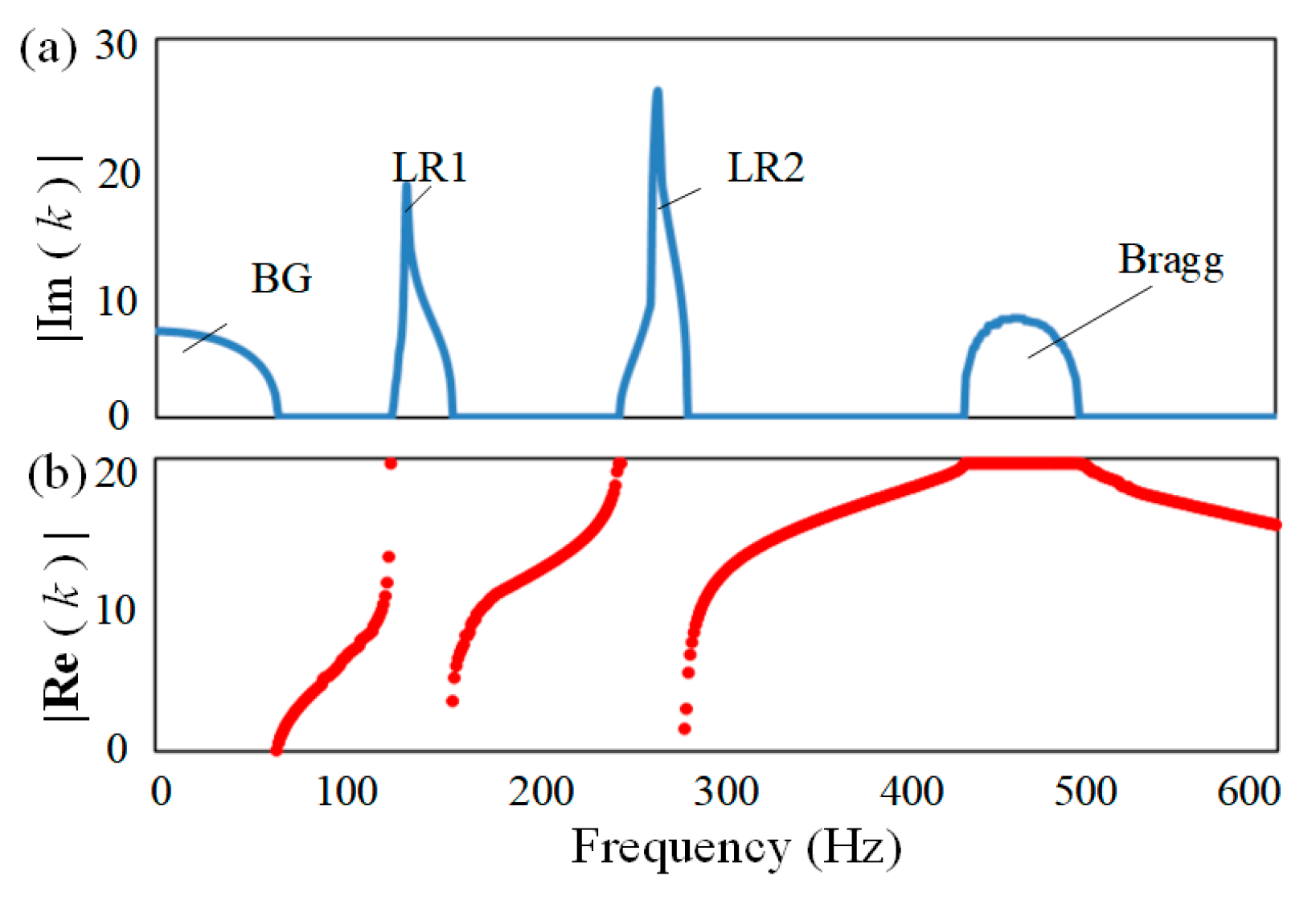
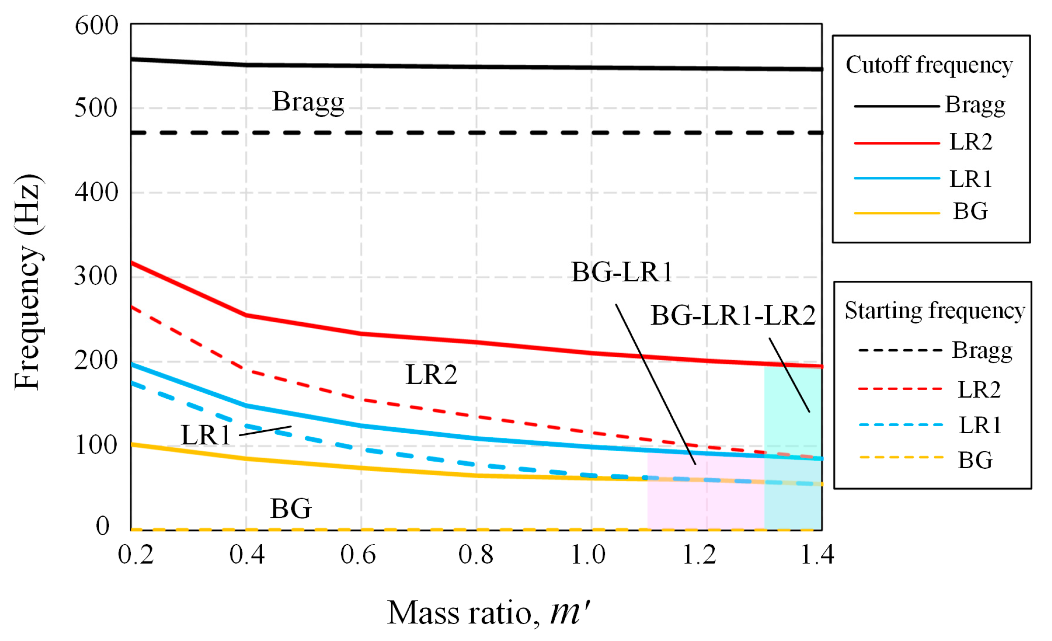
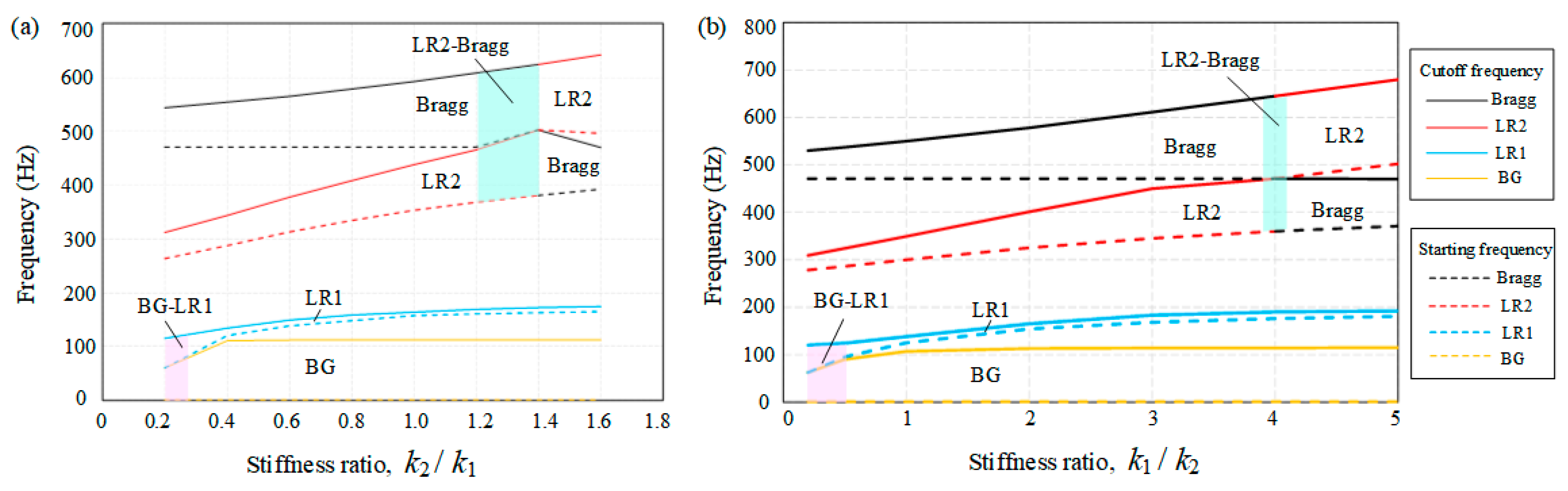
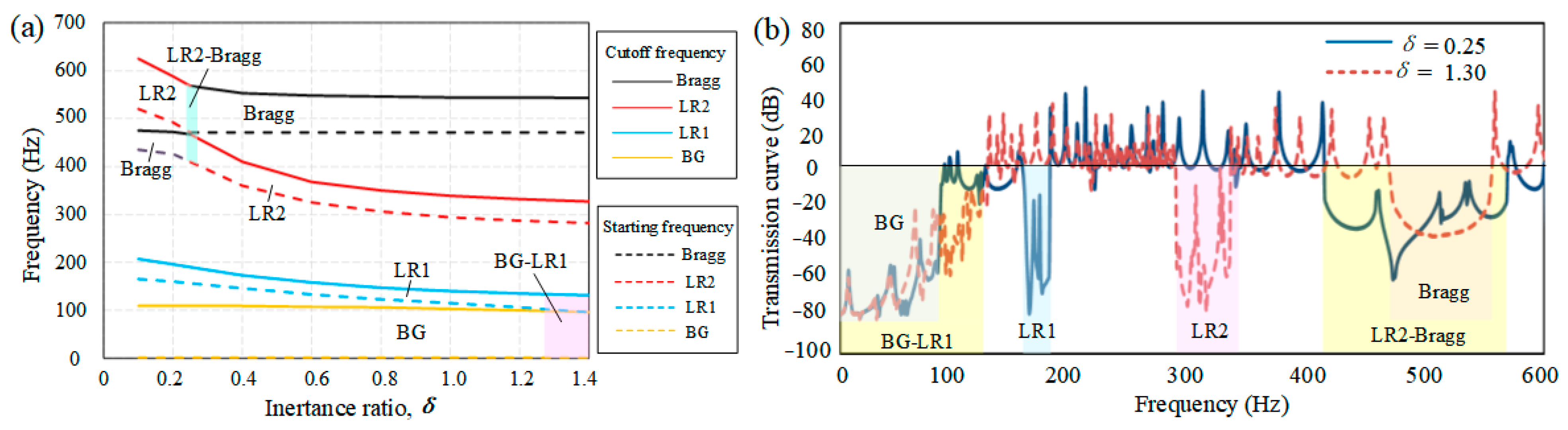
The band spectrum of the LR beam was a combination of the BG, LR1, LR2, and Bragg bands in which the LR bands caused a relatively sharper wave attenuation than the BG and Bragg bands. The two LR bands were generated by the local resonance of the additional mass and inerter in the IDVA. Therefore, the LR bands moved toward a lower-frequency range as the additional mass and inertance increased and the spring stiffness decreased.
(2)
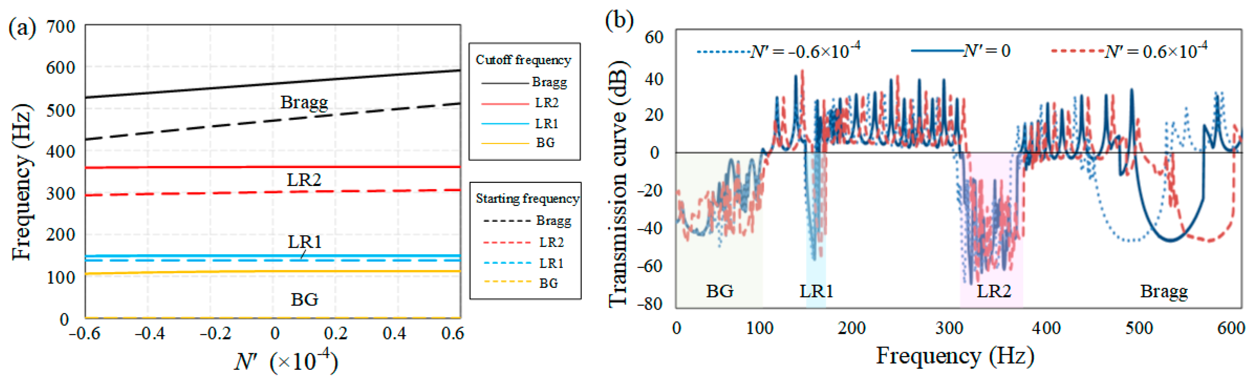
The Bragg band was determined through structural periodicity. The tensile (compressive) axial force applied to the LR beam was able to increase (decrease) the frequency range of the Bragg band, indicating that prestressing is a feasible way to tune the bandgap. The BG band located in the low-frequency zone depended on the stiffness of the vertical elastic supports, and the cutoff frequency of the BG band increased as the supports became more rigid.
(3)
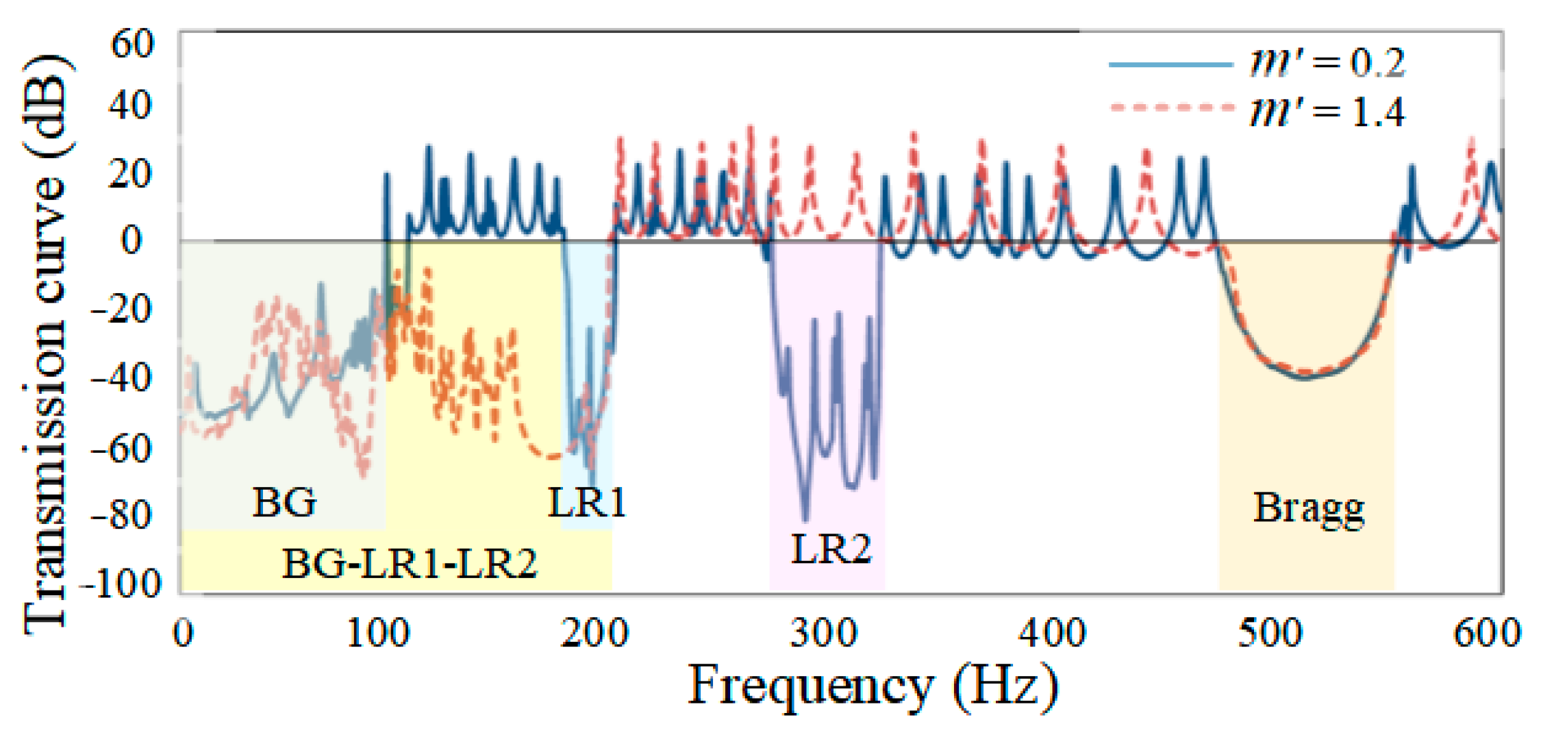
Bandgap merging accompanied by edge frequency exchange occurred for a specific combination of LR beam parameters. The bandwidth of the merged bandgap was approximately equal to the sum of the bandwidths of the bandgaps involved, suggesting that a tunable broad bandgap can be achieved through bandgap splicing.

Author Contributions

W.H.: Conceptualization, Methodology, Investigation, Data curation, Validation, Writing—original draft. S.W.: Conceptualization, Funding acquisition, Supervision, Data curation, Writing—review and editing. All authors have read and agreed to the published version of the manuscript.

Funding

This study was supported by the National Natural Science Foundation of China (Grant No. 51878151).

Institutional Review Board Statement

Not applicable.

Informed Consent Statement

Not applicable.

Data Availability Statement

Some or all data, models, or code that support the findings of this study are available from the corresponding author upon reasonable request.

Conflicts of Interest

The authors declare no conflict of interest.

References

  1. Kushwaha, M.S.; Halevi, P.; Dobrzynski, L.; Djafari-Rouhani, B. Acoustic band structure of periodic elastic composites. Phys. Rev. Lett. 1993, 71, 2022–2025. [Google Scholar] [CrossRef] [PubMed]
  2. Sigalas, M.; Economou, E. Elastic and acoustic wave band structure. J. Sound Vib. 1992, 158, 377–382. [Google Scholar] [CrossRef]
  3. Li, J.; Chan, C.T. Double-negative acoustic metamaterial. Phys. Rev. E 2004, 70, 055602. [Google Scholar] [CrossRef] [PubMed] [Green Version]
  4. Hussein, M.I.; Hulbert, G.M.; Scott, R.A. Dispersive elastodynamics of 1D banded materials and structures: Analysis. J. Sound Vib. 2006, 289, 779–806. [Google Scholar] [CrossRef] [Green Version]
  5. Mohammadi, S.; Eftekhar, A.; Khelif, A.; Moubchir, H.; Westafer, R.; Hunt, W.; Adibi, A. Complete phononic bandgaps and bandgap maps in two-dimensional silicon phononic crystal plates. Electron. Lett. 2007, 43, 898–899. [Google Scholar] [CrossRef] [Green Version]
  6. Liu, Y.; Liang, Z.; Zhu, J.; Xia, L.; Mondain-Monval, O.; Brunet, T.; Alù, A.; Li, J. Willis Metamaterial on a Structured Beam. Phys. Rev. X 2019, 9, 011040. [Google Scholar] [CrossRef] [Green Version]
  7. Liu, Z.; Chan, C.T.; Sheng, P. Three-component elastic wave band-gap material. Phys. Rev. B 2002, 65, 165116–1651166. [Google Scholar] [CrossRef] [Green Version]
  8. Yilmaz, C.; Hulbert, G.M.; Kikuchi, N. Phononic band gaps induced by inertial amplification in periodic media. Phys. Rev. B 2007, 76, 054309. [Google Scholar] [CrossRef]
  9. Yilmaz, C.; Hulbert, G. Theory of phononic gaps induced by inertial amplification in finite structures. Phys. Lett. A 2010, 374, 3576–3584. [Google Scholar] [CrossRef]
  10. Cremer, L.; Leilich, H.O. Zur theorie der biegekettenleiter. Arch. Elektr. Ubertragung 1953, 7, 261–270. [Google Scholar]
  11. Mead, D. Wave propagation and natural modes in periodic systems: II. Multi-coupled systems, with and without damping. J. Sound Vib. 1975, 40, 19–39. [Google Scholar] [CrossRef]
  12. Mead, D.M. Wave propagation in continuous periodic structures: Research contributions from Southampton, 1964–1995. J. Sound Vib. 1996, 190, 495–524. [Google Scholar] [CrossRef]
  13. Yu, D.; Liu, Y.; Wang, G.; Zhao, H.; Qiu, J. Flexural vibration band gaps in Timoshenko beams with locally resonant structures. J. Appl. Phys. 2006, 100, 124901. [Google Scholar] [CrossRef]
  14. Yu, D.; Liu, Y.; Zhao, H.; Wang, G.; Qiu, J. Flexural vibration band gaps in Euler-Bernoulli beams with locally resonant structures with two degrees of freedom. Phys. Rev. B 2006, 73, 064301. [Google Scholar] [CrossRef]
  15. Smith, M. Synthesis of mechanical networks: The inerter. IEEE Trans. Autom. Control 2002, 47, 1648–1662. [Google Scholar] [CrossRef] [Green Version]
  16. Wang, X.; Liu, X.; Shan, Y.; Shen, Y.; He, T. Analysis and Optimization of the Novel Inerter-Based Dynamic Vibration Absorbers. IEEE Access 2018, 6, 33169–33182. [Google Scholar] [CrossRef]
  17. Jin, X.; Chen, M.Z.Q.; Huang, Z. Suppressing Random Response of a Regular Structure by an Inerter-Based Dynamic Vibration Absorber. J. Vib. Acoust. 2019, 141, 041004. [Google Scholar] [CrossRef]
  18. Hu, Y.; Chen, M.Z. Performance evaluation for inerter-based dynamic vibration absorbers. Int. J. Mech. Sci. 2015, 99, 297–307. [Google Scholar] [CrossRef] [Green Version]
  19. Shen, Y.; Chen, L.; Yang, X.; Shi, D.; Yang, J. Improved design of dynamic vibration absorber by using the inerter and its application in vehicle suspension. J. Sound Vib. 2016, 361, 148–158. [Google Scholar] [CrossRef]
  20. Pietrosanti, D.; De Angelis, M.; Giaralis, A. Experimental study and numerical modeling of nonlinear dynamic response of SDOF system equipped with tuned mass damper inerter (TMDI) tested on shaking table under harmonic excitation. Int. J. Mech. Sci. 2020, 184, 105762. [Google Scholar] [CrossRef]
  21. Chen, J.; Chen, M.Z.Q.; Hu, Y. Vortex-Induced Vibration Suppression of Bridges by Inerter-Based Dynamic Vibration Absorbers. Shock. Vib. 2021, 2021, 4431516. [Google Scholar] [CrossRef]
  22. Chen, M.Z.Q.; Li, Z.; Wang, H.; Hu, Y. Seismic response mitigation of a wind turbine via inerter-based structural control. Bull. Earthq. Eng. 2023, 21, 1361–1388. [Google Scholar] [CrossRef]
  23. Zhang, S.Y.; Neild, S.; Jiang, J.Z. Optimal design of a pair of vibration suppression devices for a multi-storey building. Struct. Control Health Monit. 2019, 27, e2498. [Google Scholar] [CrossRef]
  24. Zeighami, F.; Palermo, A.; Marzani, A. Inertial amplified resonators for tunable metasurfaces. Meccanica 2019, 54, 2053–2065. [Google Scholar] [CrossRef]
  25. Dong, Z.; Sheng, P. Inertial-Amplified Mechanical Resonators for the Mitigation of Ultralow-Frequency Vibrations. Phys. Rev. Appl. 2022, 18, 014027. [Google Scholar] [CrossRef]
  26. Fang, X.; Chuang, K.-C.; Jin, X.; Huang, Z. Band-Gap Properties of Elastic Metamaterials with Inerter-Based Dynamic Vibration Absorbers. J. Appl. Mech. 2018, 85, 071010. [Google Scholar] [CrossRef]
  27. Ge, Z.; Wang, W. Modeling, Testing, and Characteristic Analysis of a Planetary Flywheel Inerter. Shock. Vib. 2018, 2018, 2631539. [Google Scholar] [CrossRef] [Green Version]
  28. Smith, M.C.; Wang, F.-C. Performance Benefits in Passive Vehicle Suspensions Employing Inerters. Veh. Syst. Dyn. 2004, 42, 235–257. [Google Scholar] [CrossRef] [Green Version]
  29. Wang, F.-C.; Hong, M.-F.; Lin, T.-C. Designing and testing a hydraulic inerter. Proc. Inst. Mech. Eng. Part C J. Mech. Eng. Sci. 2010, 225, 66–72. [Google Scholar] [CrossRef]
  30. Gei, M.; Movchan, A.B.; Bigoni, D. Band-gap shift and defect-induced annihilation in prestressed elastic structures. J. Appl. Phys. 2009, 105, 063507. [Google Scholar] [CrossRef] [Green Version]
  31. Nudehi, S.; Mukherjee, R.; Shaw, S. Active Vibration Control of a Flexible Beam Using a Buckling-Type End Force. J. Dyn. Syst. Meas. Control 2005, 128, 278–286. [Google Scholar] [CrossRef]
Figure 1. Schematic of the prestressed multisupported LR beam with IDVAs.
Sustainability 15 03680 g001
Figure 2. Bandgaps of the prestressed multisupported LR beam with IDVAs. (a) The imaginary part of wave propagation constant k. (b) The real part of wave propagation constant k.
Sustainability 15 03680 g002
Figure 3. Bandgap map of LR beam with different attached mass ratios of the IDVA.
Sustainability 15 03680 g003
Figure 4. Bandgap merging of the BG band and LR band with different mass ratios.
Sustainability 15 03680 g004
Figure 5. Transmission curve of the 30-cell LR beam carrying IDVAs with different mass ratios.
Sustainability 15 03680 g005
Figure 6. Bandgap behavior of LR beam with different IDVA spring stiffnesses. (a) k 2 / k 1 (b) k 1 / k 2 .
Sustainability 15 03680 g006
Figure 7. Bandgap merging of the LR2 and Bragg bands with different IDVA spring stiffnesses.
Sustainability 15 03680 g007
Figure 8. (a) Bandgap characteristics of the IDVA-attached LR beam with different inertance ratios. (b) Transmission curve of the 30-cell LR beam with different inertance ratios of the IDVA.
Sustainability 15 03680 g008
Figure 9. (a) Band spectrum of the IDVA-attached LR beam with different axial force. (b) Transmission curve of the 30-cell IDVA-attached LR beam with different axial forces.
Sustainability 15 03680 g009
Figure 10. (a) Band spectrum of the IDVA-attached LR beam with different stiffnesses of the vertical elastic supports. (b) Transmission curve of the 30-cell IDVA-attached LR beam with different stiffnesses of the vertical elastic supports.
Sustainability 15 03680 g010
Disclaimer/Publisher’s Note: The statements, opinions and data contained in all publications are solely those of the individual author(s) and contributor(s) and not of MDPI and/or the editor(s). MDPI and/or the editor(s) disclaim responsibility for any injury to people or property resulting from any ideas, methods, instructions or products referred to in the content.

