Article

Hydraulic Characteristics Analysis of Double-Bend Roadway of Abandoned Mine Pumped Storage

1
School of Mechanics and Civil Engineering, China University of Mining & Technology, Xuzhou 221116, China
2
State Key Laboratory for Geomechanics & Deep Underground Engineering, China University of Mining & Technology, Xuzhou 221116, China
*
Author to whom correspondence should be addressed.
Sustainability 2023, 15(5), 3958; https://doi.org/10.3390/su15053958
Submission received: 16 January 2023 / Revised: 12 February 2023 / Accepted: 14 February 2023 / Published: 22 February 2023

Abstract

:
The roadway of an abandoned mine is an ideal site for the construction of underground pumped storage hydropower, but the operation of the power station is deeply restricted by the structural characteristics of the roadway. With the common double-bend roadway of an abandoned mine as the research object, this study conducted numerical simulations based on the theory of mass conservation and momentum conservation and explored the law of the flow field characteristics and energy loss of a double-bend roadway with the roadway structure and angle. The results showed that a velocity gradient and a pressure gradient form from the outer wall to the inner wall when the fluid flows through the two bends of the roadway. The low-speed zone and maximum positive pressure appeared at the outside of the bend, while the high-speed zone and maximum negative pressure appeared at the inside of the bend. As the angle rose, the peak value of positive pressure increased correspondingly when the fluid flowed through Model A, whereas the negative pressure displayed a fluctuating trend of increasing first and then decreasing and reached its peak when β = 45°. By contrast, when the fluid flowed through Model B, the velocity gradient was symmetrically distributed at the two bends. The peak value of the positive pressure of the first bend increased, and the other positive and negative pressures displayed a trend of “first increasing and then decreasing” when the angle increased, and they reached their peak when β = 45°. When β ≥ 60°, the fluid formed a backflow zone when it flowed through each bend. With an increase in the angle, the area of the backflow zone increased correspondingly. The head loss of the two models increased with the angle. At the same angle, the head loss of Model B was greater than that of Model A. According to the requirement of abandoned mine pumped storage, the roadways with a bend angle of 15° or 30° in Model A and 15° in Model B can be used. The research results can provide some reference for the underground space exploitation and utilization of abandoned mine pumped storage.

1. Introduction

The carbon peaking and carbon neutrality goals accelerate the optimization of energy structures and the process of low-carbon development. With the advancement of overcapacity reduction in the coal industry, more and more coal mines have been closed. According to statistics, 7448 mines closed during the 13th Five-Year Plan period [1,2], with the number expected to reach 15,000 by 2030 [3,4,5,6,7], leaving an underground space of about 90 billion cubic meters [8]. To realize the full utilization of abandoned mine resources and the collaborative development of renewable energy development, Yuan Liang, Xie Heping et al. [9,10,11,12,13] put forward a new key energy storage technology called abandoned mine pumped storage. At present, the underground reservoirs of abandoned mine pumped storage are mainly built by abandoned roadways. However, the complex geometric structure of roadways affects the fluidity of water and reduces energy storage efficiency. In January 2022, “The 14th Five-Year Plan for the Development of new Energy Storage”, jointly released by the National Development and Reform Commission and the Ministry of Energy, emphasized the importance of this new key energy storage technology, which can simultaneously solve the problems of space utilization of abandoned mines and improve the utilization rate of renewable energy sources. Therefore, it is important for the development of abandoned mine pumped storage to study the topological relationship of the underground space of abandoned mines and to select suitable roadways for the construction of the reservoir.
In recent years, the study on the site selection of the underground reservoirs of abandoned mine pumped storage has attracted widespread attention. Nzotcha et al. [14] put forward the influencing factors for site selection, including technology, economy, social, and environmental considerations, from the perspective of sustainability. Vasileios Kitsikoudis et al. [15] used numerical simulation to simulate the abandoned mine chamber as the reservoir of an underground pumped storage power station and quantitatively analyzed the influence of connecting passage sections between connecting chambers and chamber ventilation on the change in water level of the underground reservoir. Based on the threshold theory, Wang Bing et al. [16] proposed a preliminary selection model for the site of the abandoned mine pumped storage power station and explored the site selection of the pumped storage power station by way of a fuzzy multi-criteria decision model. Based on the characteristics of different levels of mines, Zhu Chaobin et al. [17] expounded the analysis method of the underground space structure of abandoned mines from the perspective of space syntax and established a topological model of underground space of small-scale multivariate convex space. Javier Menéndez et al. [18] simulated different tunnel network models to study the air–water two-phase flow characteristics. On this basis, they also evaluated the safety of the tunnel. In addition, they used MATLAB and Fluent to conduct numerical analysis and simulation of the water pump shutdown and first operation stage and explored the influence of the size of the ventilation shaft surge chamber on the operation safety and energy storage efficiency of the power station [19,20]. Estanislao Pujades et al. used the finite element numerical code SUFT 3D to establish a numerical model of groundwater flow. Considering the two actual initial conditions of complete depletion and complete injection of water in the groundwater reservoir, they evaluated the hydraulic exchange effects of the mine reservoir and roadway surrounding rock when the power station was in operation for a long time [21,22,23]. Based on the flow equation of air and water under different operating conditions of the abandoned mine pumped storage power station, Ye Peng [24] used the Fluent software to conduct numerical simulation and analyzed the influence of different geometric designs on water–air flow characteristics as well as water energy utilization rate under each operating conditions. Rudakov, D. et al. [25] presented and validated an analytical model of water inflow and rising levels in a flooded mine and examined the model’s robustness and sensitivity to variations of input data considering the examples of three closed hard coal mines. However, the above studies mainly consider the influence of external factors such as economy and environment, as well as the roadway structure, such as the ventilation shaft and surge chamber, on the overall space of the roadway. Quite little has been done to explore the site selection of power stations from the local geometric features of the roadway.
In view of the above problems, this study selected two typical underground double-bend roadways to establish three-dimensional models and used Fluent software to conduct numerical simulations of various models under turbine operating conditions to analyze the fluid velocity field and pressure field under different tunnel geometric characteristics, as well as the influence of tunnel geometric characteristics on energy storage efficiency. The research results can provide a certain reference for the underground space planning and utilization of abandoned mine pumped storage.

2. Numerical Model of the Double-Bend Roadway in Abandoned Mine

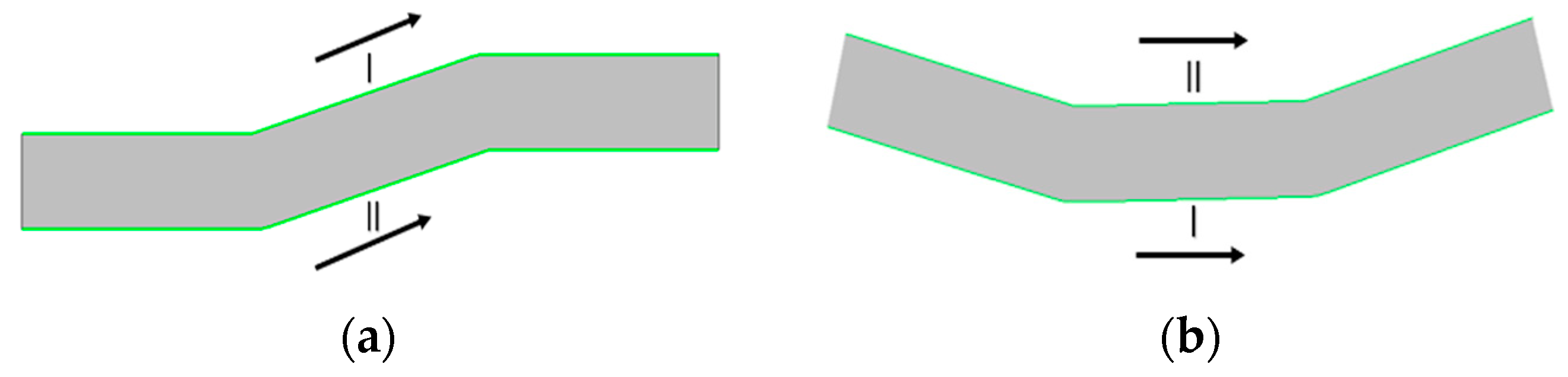
2.1. The Establishment of the Geometric Model

Due to the needs of mining, the roadway of abandoned mines have different shapes and many bends, and the spacing between bends is commonly short. Therefore, a roadway with two continuous and short-spaced bends can be represented as a “double-bend roadway”. As is shown in Figure 1, the two types of double-bend roadways in the Longdong Mine in Xuzhou, Jiangsu Province, are highly representative of a double-bend roadway. Double-bend roadways have a great impact on the energy storage efficiency and surrounding rock stability of abandoned mine pumped storage. Therefore, this study established two geometric models based on two typical double-bend roadways in Longdong Mine (Model A and Model B). The mining depth of Longdong Mine is −300 m, and the roadway section is a semicircular arch shape, with a width of 4700 mm and a height of 3750 mm.
The geometric models were created by SolidWorks software, and the model size was designed according to the roadway data of Longdong Mine. Given the small slope and long length of the roadway, the slope of the roadway was not considered, and the roadway length before and after the bend was uniformly 15 m. The working models of this simulation were Model A and Model B, as shown in Figure 2. The two models were further divided into six types according to the different bend angles. The bend angle β of the roadway refers to the angle between the inflow direction and the transition section, which was set to 15°, 30°, 45°, 60°, 75°, and 90°, respectively. In order to simulate the real roadway, smooth processing was done in the bending parts. Meanwhile, in order to avoid the influence of gravity on the fluid in the roadway, the gravity direction of the numerical simulation of the roadway was the -Y direction of the model. All the models were placed horizontally, and there was no height difference between the inlet and outlet.

2.2. Governing Equation

In the turbine operating condition of abandoned mine pumped storage, the roadway will be filled with fluid, which mainly consists of two phases, water and air, and mainly presents stratified flow. Heat exchange is not considered in the process, so the fluid flow governing equations mainly include the momentum conservation equation, continuity equation, and volume fraction conservation equation [24]. The specific equations are as follows:
Momentum conservation equation:
t ( ρ υ ) + ( ρ υ υ ) = p + [ μ ( υ + υ T ) ] + ρ g + F ,
Continuity equation:
ρ t + ( ρ V ) = 0 ,
Volume fraction conservation equation:
α q t + V q q α q = S ρ q + 1 ρ q p = 1 n ( m ˙ p q m ˙ q p ) ,
where  ρ  denotes the mean density of two-phase flow;  V  denotes the mean velocity of two-phase flow;  t  is time;  ν  represents the velocity vector;  μ  refers to the fluid dynamic viscosity;  p  denotes the pressure on the element;  F  denotes the mass force on the element;  α q  is the volume fraction of  q -phase fluid;  V q  denotes the fluid velocity of  q -phase fluid;  S  refers to the cross-sectional area of the control volume;  ρ q  denotes the mean density of  q -phase flow;  m ˙ p q  is the mass transport from  p -phase to  q -phase; and  m ˙ q p  is the mass transport from  q -phase to  p -phase.

2.3. Model Solution Setup

The mesh generation of the models was conducted by means of the mesh module under the Workbench platform. The total mesh of each model reached up to 450,000. The pressure base solver was used for transient calculation, and the gravity acceleration in the negative direction of the Y-axis was set as −9.8 m2/s. The k-epsilon Re-Normalization Group (RNG) model was selected as the turbulence model; for the two-phase (water and air) modeling, the Volume Of Fluid (VOF) approach was selected. In order to enhance computational stability, the option “Implicit Body Force” was activated. The primary phase was water, and the secondary phase was air. The gas was ideal air, and the water was incompressible, and they were considered to have constant densities and dynamic viscosities. The values for air were a density of 1.225 kg/m3 and a dynamic viscosity of 1.789 × 10⁻⁵ kg/ms, and for water, a density of 998 kg/m3 and a dynamic viscosity of 1.003 × 10⁻³ kg/ms. The surface tension coefficient between water and air was set as 0.073 N/m. In this paper, the roadway of Longdong Mine was taken as the reservoir, so the mining depth of the mine was taken as the basis for the pressure setting. The inlet boundary condition was set as the pressure inlet, with a pressure of 300 mH2O; the outlet boundary condition was set as the pressure outlet, with atmospheric pressure. The operating pressure value was set to the atmosphere. The solid wall boundary was set as no-slip by default, with a surface roughness of 3 mm. The transient form of the Pressure-Implicit with the Splitting of Operators (PISO) algorithm was used. Standard initialization was adopted and proceeded from the inlet. The maximum residual of all parameters was set as 1 × 10⁻⁵; the time step was set as 0.001 s, with 10,000 steps in total; and the maximum number of iteration steps was 500.

3. Results and Analysis

3.1. The Velocity Field Analysis of the Double-Bend Roadway

Figure 3 and Figure 4 show the velocity nephogram and flow diagram of the cross-section with a height of 1.3 m at different bend angles. As is shown in the figures, the fluid velocity in the middle of the roadway is greater than that near the roadway wall. This is due to the viscosity of the fluid, which makes the fluid velocity near the wall equal to zero. Before entering the first bend, the distribution of fluid velocity in the middle is relatively uniform; after the fluid enters the first bend, a velocity gradient is formed from the outer wall to the inner wall due to centrifugal force. The outside of the bend is a low-speed zone, while the inside is a high-speed zone. The velocity change in the fluid at the second bend is similar to that at the first one. The velocity at the outlet decreases with the increase in the angle because the impact and friction between the fluid and the wall increase with the increase in the angle; the more mainstream energy dissipation, the greater the head loss, and the average velocity at the outlet decreases. As the angle increases, the velocity around the bend changes obviously, and the area with an obvious difference in velocity changes tends to increase with the angle. When the fluid flows through Model A, the range of the high- and low-speed zone in the second bend is larger due to the influence of the first bend. By contrast, when the fluid flows through Model B, the velocity gradient is symmetrically distributed at the two bends.
When the angle is greater than or equal to 60°, there is an obvious backflow zone when the fluid flows through the two bends. This is because the fluid inside the bend is separated from the roadway wall by centrifugal force, the mainstream is compressed, and energy is dissipated, thus generating a backflow zone on the cross-section. The backflow zone spreads along the roadway wall from the first bend to the second one, and it increases with the bend angle. To be specific, when the bend angle is 90°, the backflow zone formed by the fluid flowing through Model A accounts for half of the cross-section area. This is because, with the increase in bend angle, the roadway produces more extrusion on the fluid, changing the flow direction and state of the fluid and increasing the internal disturbance of the fluid, which finally leads to a decrease in the fluid velocity. As can be seen from Figure 4, there is no backflow at the outlet, indicating that the fluid flow has been fully developed at the outlet.

3.2. The Pressure Field Analysis of the Double-Bend Roadway

Figure 5 displays the pressure nephogram of the cross-section with a height of 1.3 m of the two models at different bend angles. As is shown in the figures, in the initial stage of fluid flowing in the roadway, the pressure changes uniformly in Model A; by contrast, it gradually decreases in Model B. With the fluid flowing, the fluid forms a pressure gradient from the outside to the inside at the first and second bends. The maximum positive pressure appears on the outside of the roadway bend, and the maximum negative pressure appears on the inside of the roadway bend. This is because when the fluid flows to the bend, the local boundary of the roadway changes sharply, resulting in the separation of the mainstream from the roadway wall, which also changes the structure and velocity distribution of the flow. The mainstream is squeezed to the outside of the bend, and negative pressure is formed inside the bend. Under the action of inertia, the fluid causes an impact on the roadway wall, and the pressure on the outer wall increases, which consumes energy. After flowing through the first bend, the influence of the local boundary on the flow state is weakened, the direction of the mainstream is restored, and the pressure distribution is also restored to the uniform state. After flowing through the second bend, the boundary changes again, leading to a change in the direction of the mainstream, and the mainstream energy is further reduced. However, the maximum pressure on both the outside and inside of the second bend is lower than that of the first bend. For a double-bend roadway with the same model, the increase in angle leads to an increase in head loss, while pressure changes also increase. The main reason is that the larger the angle, the greater the inertial force of the fluid to overcome and the more energy required. Of the two models, the pressure gradient of Model A is the largest. With the increase in the angle, the negative pressure zone formed by the fluid at the two bends increases correspondingly. When β = 90°, the negative pressure region reaches its maximum and traverses the entire section when the fluid flows through Model A, which is mainly caused by the roadway structure. When the fluid flows through Model A, it collides with the roadway wall at the bend, while in Model B, the two bends have a smoother transition and follow the direction of fluid flow, which is conducive to the movement of the fluid.
In addition, when the fluid flows through the two bends of the roadway, the inner pressure gradient changes from positive to negative, indicating the occurrence of fluid separation. The reason for this phenomenon is that: when the fluid flows through the bend, it is constrained by the bend wall, and the outer wall forces the fluid to turn, thus generating centrifugal force; this, in turn, results in the phenomenon that the closer it gets to the outer wall, the higher the pressure is. By contrast, the fluid on the inner wall tends to fall off, and the closer it gets to the inner wall, the higher the negative pressure is. Combined with the results of velocity field analysis, it can be known that the presence of a roadway bend subjects the fluid to centrifugal force and inertia and that the change in flow direction leads to the change in the internal flow field and the formation of the backflow zone. As indicated by the comparison of Figure 4 and Figure 5, the negative pressure zone coincides with the backflow zone. This shows that the backflow zone formed by the roadway bends would cause the energy loss of the fluid, which in turn results in pressure decay and hydraulic head loss and vibration. Accordingly, the energy loss of fluid in the roadway mainly consists of the loss that causes the change in the flow direction, the loss of the flow velocity distribution caused by centrifugal force, the loss along the fluid flow, and so on.

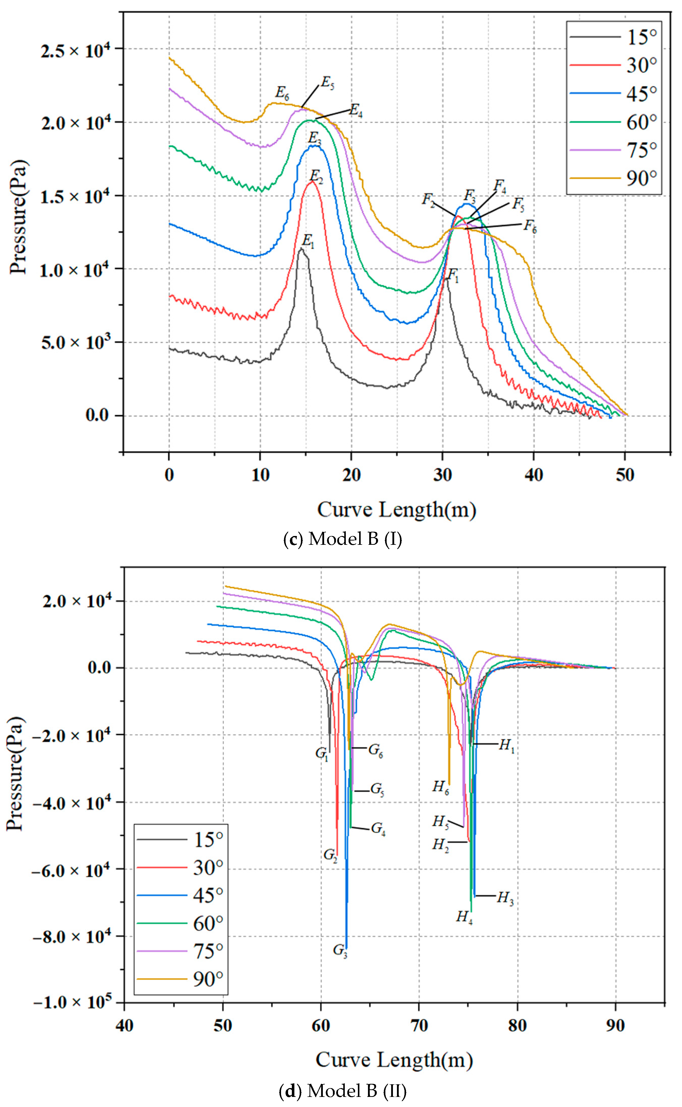
3.3. The Pressure Analysis along the Line
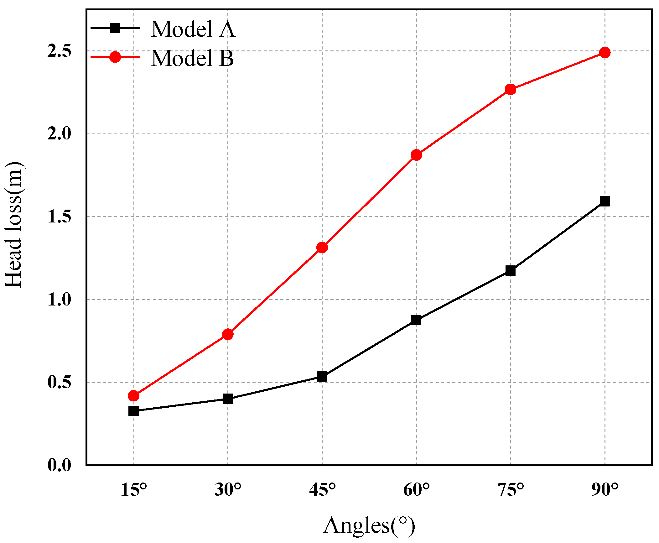
Figure 6 shows the intersection line between the cross-section with a height of 1.3 m and the roadway wall when the bend angle of the two models is 15°. Figure 7 displays the distribution of the pressure along the line of the two models (length calculated from I→II) at different bend angles. The peak pressure points inside the first bend, outside the second bend, outside the first bend, and inside the second bend of Model A are denoted as A, B, C, and D, respectively; inside the first bend, inside the second bend, outside the first bend, and outside the second bend of Model B are denoted as E, F, G, and H, and the bend angle is denoted as 1, 2, 3, 4, 5, and 6. Then, the peak point of Model A, when the first bend angle is 15°, is denoted as A1, and so on for other peak points. As can be seen from Figure 6 and Figure 7, positive pressure appears outside the bend, and negative pressure appears inside the bend. When the fluid flows through the straight part of Model A, the pressure changes uniformly, whereas when it flows through the straight part of Model B, the pressure decreases gradually. When the fluid flows through the two bends, the pressure on the outer and inner side both increases first and then decrease. When the fluid flows through the bends of Model A, the peak positive pressure increases as the angle increases and the peak value reaches its maximum when β = 90°, whereas the peak value of negative pressure increases first and then decreases, and the peak value of negative pressure reaches the maximum when β = 45°. By contrast, when the fluid flows through the bends of Model B, the peak value of the positive pressure of the first bend increases, and the other positive and negative pressures display a trend of “first increasing and then decreasing” when the angle increases and they reach the maximum when β = 45°.
In addition, when the fluid flows through the roadway whose bend angle is equal to or greater than 60°, the pressure along the line oscillates, and the position where the pressure converts from negative to positive delays as the bend angle increases. Combined with the velocity field and pressure field analysis results, it can be known that this phenomenon is caused by the fluid backflow occurring in this part. Specifically, the greater the bend angle, the greater the backflow area.

3.4. Energy Loss

As can be known from the above analyses, when the fluid flows past the bends of the roadway, it changes its flow direction under the action of the roadway wall. In this process, part of its energy is consumed, and the pressure experiences a significant and sudden drop correspondingly. In fact, the larger the bend angle becomes, the greater the pressure drop and the greater the energy loss. Accordingly, the energy loss caused by the double-bend roadway can be analyzed by the mean pressure difference between the inlet section and the outlet section.
The geometric model in Figure 2 was set as the research control body, with the inlet as Section 1 and the outlet as Section 2, and the total flow Bernoulli Equation (4) between the inlet and outlet of the model was established, thus obtaining the local head loss of the roadway (5):
z 1 + P 1 ρ g + α 1 υ 1 2 2 g = z 2 + P 2 ρ g + α 2 υ 2 2 2 g + h f 1 2 ,
h f 1 2 = z 1 z 2 + P 1 P 2 ρ g + α 1 υ 1 2 α 2 υ 2 2 2 g ,
where  z 1  and  z 2  denote the position head of the inlet and outlet, respectively, m;  v 1  and  v 2  denote the mean velocity of the inlet and outlet, respectively, m/s;  P 1  and  P 2  denote the pressure of the inlet and outlet, respectively, Pa;   h f 1 2  denotes the head loss between the inlet and the outlet; and  α  refers to the kinetic energy correction factor. Where  α  is correlated with the velocity distribution on the cross-section. When the velocity distribution is relatively uniform,  α  is close to one. As is shown by the simulation results, both  α 1    and  α 2  are one. Since there is no height change in the roadway,  z 1  =  z 2 . Accordingly, Equation (5) can be simplified as:
h f 1 2 = P 1 P 2 ρ g + υ 1 2 υ 2 2 2 g ,
P s 1 = P 1 , P s 2 = P 2
P d 1 = ρ υ 1 2 2 , P d 2 = ρ υ 2 2 2
P t 1 = P s 1 + P d 1 , P t 2 = P s 2 + P d 2
where  P s 1  and  P s 2  denote the static pressure of the inlet and outlet, respectively, Pa;  P d 1  and  P d 2  denote the dynamic pressure of the inlet and outlet, respectively, Pa;  P t 1  and  P t 2  denote the total pressure of the inlet and outlet, respectively, Pa; and  ρ  denotes the fluid density, kg/m3.
Substituting Equations (7)–(9) into Equation (6), the local head loss in the roadway can be obtained as follows:
h f 1 2 = P t 1 P t 2 ρ g
Figure 8 displays the changing curves of head loss of the two models at different bend angles. As can be seen, the head loss increases as the bend angle increases. When the bend angle is 90°, the energy loss of Model A is 1.6 m while that of Model B is 2.5 m. The head loss caused by the fluid flowing through Model A increases uniformly as the bend angle increases. By contrast, the growth rate of the head loss of Model B increases first and then decreases. Specifically, when the bend angle is within the range of 0~60°, the growth rate is fast, indicating that the bend angle exerts a significant impact on the head loss when the bend angle is within the range of 0~60°. In addition, at the same bend angle, the head loss of Model B is greater than that of Model A.
In order to further study the influence of the double-bend roadway on the flow characteristics, a straight roadway was simulated with the same method, considering only the influence of bend angle on the flow characteristics with the other conditions unchanged. Through calculation, it can be known that the head loss along the straight roadway is 0.30 m, which is marked as H. Then the head loss caused by the fluid flowing through Model A can be characterized as 1.09 H, 1.32 H, 1.77 H, 2.89 H, 3.88 H, and 5.26 H and those of Model B are 1.39 H, 2.61 H, 4.34 H, 6.18 H, 7.49 H, and 8.23 H, respectively. According to the storage requirements of abandoned mine pumped storage, the roadways with a bend angle of 15° or 30° in Model A and 15° in Model B can be used as water storage roadways.
When the initial pressure of the straight roadway is set to 50 mH2O, 100 mH2O, and 200 mH2O, the head loss calculated is 0.03 m, 0.07 m, and 0.18 m, respectively. Therefore, it can be safely concluded that the greater the pressure on the inlet, the greater the head loss. As can be known from Equation (10), the local head loss of a double-bend roadway can be calculated by the pressure difference between the inlet and outlet. If the inlet pressure of the double-bend roadway is large, the local head loss will be large correspondingly. Therefore, in the design of the abandoned mine pumped storage power station, the catchment channel of the power station should be selected far away from the bend so that when the fluid flows to the bending section, the inlet pressure will be smaller, thus reducing the local head loss and improving the energy storage efficiency.

4. Feasibility Analysis of Abandoned Mine Pumped Storage

In the working process of abandoned mine pumped storage hydropower, the fluid acts circularly on the surrounding rock and affects the stability and tightness of the surrounding rock. Therefore, it is easier to analyze the failure and disaster control mechanism of the surrounding rock by studying hydraulic characteristics, and on this basis, the long-term stability control technology of the surrounding rock is proposed. Furthermore, the fluid may affect the load-carrying capacity of machinery and equipment. Learning hydraulic characteristics can reduce their damage and provide technical support for the selection of pump turbines and the construction of power stations. The study of hydraulic characteristics can provide an optimal design method for the efficient operation of abandoned mine pumped storage systems.
In view of the research, there are some prospects: (a) this paper considers the hydraulic characteristics of abandoned mine pumped storage from the perspective of short-distance and double-bend roadways. However, in reality, roadways have many continuous bends, and the simulated results are different from the actual process. (b) This paper only considers the hydraulic characteristics of abandoned mine pumped storage under the turbine operating condition, while the pump operating condition also needs to be considered. (c) This paper ignores the effect of bend section spacing on the model, which will be the content of subsequent research. (d) This study only studies the hydraulic characteristics under the single turbine working condition. However, in reality, the operation process is a pumping cycle process, and the roadway will be deformed and damaged by the action of circulating force. Therefore, it is necessary to study the stability of the surrounding rock and put forward corresponding support control countermeasures based on the failure characteristics of the surrounding rock in the follow-up to effectively improve the stability of the surrounding rock structure. (e) The change in fluid characteristics under the action of gravity and roadways with different geometric shapes will affect the safe operation of machinery and equipment and thus affect the selection and design of equipment, which should be taken into account in the subsequent research.

5. Conclusions

The roadway of an abandoned mine is an ideal site for the construction of underground pumped storage hydropower. However, the complex geometric structure of roadways affects the fluidity of water and reduces energy storage efficiency. Therefore, it is necessary to explore the influence of local geometric features of the roadway on hydraulic characteristics. In this paper, Fluent software was used to conduct numerical simulations of two typical double-bend roadways, and the research results show the following.
As the fluid flows through the bends of the two roadways, a velocity gradient increasing from the outer wall to the inner wall appears in both Models. However, when the fluid flows through Model A, due to the influence of the first bend on the fluid flow, the range of the high- and low-speed zone in the second bend is larger; and it displays a rising trend with the increase in bend angle and reaches its peak value when the bend angle is 90°. By contrast, when the fluid flows through Model B, the velocity gradient is symmetrically distributed at the two bends.
The fluid forms a hydrostatic pressure gradient from the outer wall to the inner wall at both bends. The maximum positive pressure appears on the outside of the bend, and the maximum negative pressure on the inside of the bend. As the bend angle rises, the peak value of positive pressure increases correspondingly when the fluid flows through Model A, whereas the peak value of negative pressure displays a fluctuating trend of increasing first and then decreasing. When β = 90°, the positive pressure reaches its peak; when β = 45°, the negative pressure reaches its peak. By contrast, when the fluid flows through Model B, the peak value of the positive pressure of the first bend increases, and the other positive and negative pressures display a trend of “first increasing and then decreasing” when the bend angle increases and they reach their peak value when β = 45°.
When β ≥ 60°, under the action of centrifugal force and inertia, the internal flow field changes. When the fluid flows through each bend, it forms a backflow zone from the inflection point, and the backflow zone spreads along the wall from the first inflection point to the second bend. With the increase in the bend angle, the area of the backflow zone increases correspondingly.
The head loss of the two models increases with the increase in the bend angle. At 90°, the energy loss of Model A is 1.6 m, and that of Model B is 2.5 m. At the same bend angle, the head loss of Model B is greater than that of Model A. According to the requirements of pumped storage power stations in abandoned mines, roadways with a bend angle of 15° or 30° in Model A and 15° in Model B can be used as water storage roadways.
Based on the hydraulic characteristics of abandoned mine pumped storage, the feasibility of this study was analyzed from the stability of the surrounding rock, the safety of the machinery and equipment, and the optimization of site selection, and the prospect of this study was put forward.

Author Contributions

Conceptualization, X.Z. and Y.Z.; methodology, X.Z.; software, X.Z.; validation, X.Z.; formal analysis, X.Z.; investigation, X.Z.; resources, X.Z.; data curation, X.Z.; writing—original draft preparation, X.Z.; writing—review and editing, Y.Z., X.X., C.Z. (Chunlin Zeng), and C.Z. (Chaobin Zhu); visualization, X.Z.; supervision, X.Z.; project administration, X.Z.; funding acquisition, X.Z. All authors have read and agreed to the published version of the manuscript.

Funding

This research was funded by the National Natural Science Foundation of China (grant number No. 52061135111) and the National Key R&D Program of China (grant number No. 2022YFE0129100).

Institutional Review Board Statement

Not applicable.

Informed Consent Statement

Not applicable.

Data Availability Statement

The data presented in this study are available upon request from the corresponding author.

Conflicts of Interest

The authors declare no conflict of interest.

References

  1. Sun, W.J.; Ren, S.L.; Wu, Q.; Dong, D.L.; Gan, X.Y. Waterpollution’s prevention and comprehensive utilization of abandoned coal mines in China under the new normal life. J. China Coal Soc. 2022, 47, 2161–2169. [Google Scholar]
  2. Sun, Y.J.; Xu, Z.M.; Li, X.; Zhang, L.; Chen, G.; Zhao, X.M.; Gao, Y.T.; Liu, Q.; Zhang, S.G.; Wang, W.J.; et al. Mine water drainage pollution in China’s coal mining areas and the construction of prevention and control technical system. Coal Geol. Explor. 2021, 49, 1–16. [Google Scholar]
  3. Yuan, L.; Jiang, Y.D.; Wang, K.; Zhao, Y.X.; Hao, X.J.; Xu, C. Precision exploitation and utilization of closed/abandoned mine resources in China. J. China Coal Soc. 2018, 43, 14–20. [Google Scholar]
  4. Xie, H.P.; Wu, L.X.; Zheng, D.Z. Prediction on the energy consumption and coal demand of China in 2025. J. China Coal Soc. 2019, 44, 1949–1960. [Google Scholar]
  5. Yuan, L.; Yang, K. Further discussion on the scientific problems and countermeasures in the utilization of abandoned mines. J. China Coal Soc. 2021, 46, 16–24. [Google Scholar]
  6. Yuan, L. Scientific conception of precision coal mining. J. China Coal Soc. 2017, 42, 1–7. [Google Scholar]
  7. Yuan, L. Strategic thinking of simultaneous exploitation of coal and gas in deep mining. J. China Coal Soc. 2016, 41, 1–6. [Google Scholar]
  8. Wang, S.M.; Shen, Y.J.; Sun, Q.; Liu, L.; Shi, Q.M.; Zhu, M.B.; Zhang, B.; Cui, S.D. Underground CO2 storage and technical problems in coal mining area under the “dual carbon” target. J. China Coal Soc. 2022, 47, 45–60. [Google Scholar]
  9. Yuan, L.; Zhang, T.; Zhang, Q.H.; Jiang, B.Y.; Lü, X.; Li, S.S.; Fu, Q. Construction of green, low-green and multi-energy completmentary system for abandoned mines under global carbon neutrality. J. China Coal Soc. 2022, 47, 2131–2139. [Google Scholar]
  10. Xie, H.P.; Gao, M.Z.; Gao, F.; Zhang, R.; Ju, Y.; Xu, H.; Wang, Y.W. Strategic conceptualization and key technology for the transformation and upgrading of shut-down coal mines. J. China Coal Soc. 2017, 42, 1355–1365. [Google Scholar]
  11. Xie, H.P.; Gao, M.Z.; Liu, J.Z.; Zhou, H.W.; Zhang, R.X.; Chen, P.P.; Liu, Z.Q.; Zhang, A.L. Research on exploitation and volume estimation of underground space in coal mines. J. China Coal Soc. 2018, 43, 1487–1503. [Google Scholar]
  12. Xie, H.P.; Hou, Z.M.; Gao, F.; Zhou, L.; Gao, Y.N. A new technology of pumped-storage power in underground coal mine: Principles, present situation and future. J. China Coal Soc. 2015, 40, 965–972. [Google Scholar]
  13. Bian, Z.F.; Zhou, Y.J.; Zeng, C.L.; Huang, J.; Pu, H.; Axel, P.; Zhang, B.S.; Habil, C.B.; Bai, H.B.; Meng, Q.B.; et al. Discussion of the basic problems for the construction of under-ground pumped storage reservoir in abandoned coal mines. J. China Coal Soc. 2021, 46, 3308–3318. [Google Scholar]
  14. Nzotcha, U.; Kenfack, J.; Manjia, M.B. Integrated multi-criteria decision making methodology for pumped hydro-energy storage plant site selection from a sustainable development perspective with an application. Renew. Sustain. Energy Rev. 2019, 112, 930–947. [Google Scholar] [CrossRef]
  15. Kitsikoudis, V.; Archambeau, P.; Dewals, B.; Pujades, E.; Orban, P.; Dassargues, A.; Pirotton, M.; Erpicum, S. Underground Pumped-Storage Hydropower (UPSH) at the Martelange Mine (Belgium): Underground Reservoir Hydraulics. Energies. 2020, 13, 3512. [Google Scholar] [CrossRef]
  16. Wang, B.; Liu, P.S.; Deng, K.L. Site selection of pumped storage power station in abandoned mines: Results from fuzzy-based multi criteria decision model. J. Min. Sci. Technol. 2021, 6, 667–677. [Google Scholar] [CrossRef]
  17. Zhu, C.B.; Zhou, Y.J.; Bian, Z.F.; Chen, N.; Xia, C.Y.; Bai, H.B. Topological model construction and space optimization of abandoned mine pumped storage from the perspective of space syntax. J. China Coal Soc. 2022, 47, 2279–2288. [Google Scholar]
  18. Menéndez, J.; Loredo, J.; Galdo, M.; Fernandez-Oro, J.M. Energy storage in underground coal mines in NW Spain: Assessment of an underground lower water reservoir and preliminary energy balance. Renew. Energy 2019, 134, 1381–1391. [Google Scholar] [CrossRef]
  19. Menéndez, J.; Fernandez-Oro, J.M.; Galdo, M.; Loredo, J. Transient Simulation of Underground Pumped Storage Hydropower Plants Operating in Pumping Mode. Energies 2020, 13, 1781. [Google Scholar] [CrossRef] [Green Version]
  20. Menéndez, J.; Fernandez-Oro, J.M.; Galdo, M.; Loredo, J. Pumped-storage hydropower plants with underground reservoir: Influence of air pressure on the efficiency of the Francis turbine and energy production. Renew. Energy 2019, 143, 1427–1438. [Google Scholar] [CrossRef]
  21. Pujades, E.; Orban, P.; Archambeau, P.; Kitsikoudis, V.; Erpicum, S.; Dassargues, A. Underground Pumped-Storage Hydropower (UPSH) at the Martelange Mine (Belgium): Interactions with Groundwater Flow. Energies 2020, 13, 2353. [Google Scholar] [CrossRef]
  22. Brouyère, S.; Orban, P.; Wildemeersch, S.; Couturier, J.; Gardin, N.; Dassargues, A. The Hybrid Finite Element Mixing Cell Method: A New Flexible Method for Modelling Mine Ground Water Problems. Mine Water Environ. 2009, 28, 102–114. [Google Scholar] [CrossRef] [Green Version]
  23. Wildemeersch, S.; Brouyère, S.; Orban, P.; Couturier, J.; Dingelstadt, C.; Veschkens, M.; Dassargues, A. Application of the Hybrid Finite Element Mixing Cell method to an abandoned coalfield in Belgium. J. Hydrol. 2010, 392, 188–200. [Google Scholar] [CrossRef] [Green Version]
  24. Ye, P. Fluid Dynamics Analysis and Structural Optimization Design of Underground Pumped-Storage Power Station in Abandoned Coal Mine. Master’s Thesis, China University of Mining and Technology, Xuzhou, China, 2020. [Google Scholar]
  25. Rudakov, D.; Westermann, S. Analytical modeling of mine water rebound: Three case studies in closed hard-coal mines in Germany. Min. Miner. Depos. 2021, 15, 22–30. [Google Scholar] [CrossRef]
Figure 1. The two types of double-bend roadways of Longdong Mine.
Sustainability 15 03958 g001
Figure 2. The geometric model of: (a) Model A; (b) Model B; (c) Longitudinal section of Model A and Model B.
Sustainability 15 03958 g002
Figure 3. The velocity nephogram of the cross-section with a height of 1.3 m of Model A (a) and Model B (b) at different bend angles.
Sustainability 15 03958 g003
Figure 4. The flow diagram of the cross-section with a height of 1.3 m of Model A (a) and Model B (b) at different bend angles.
Sustainability 15 03958 g004
Figure 5. The pressure nephogram of the cross-section with a height of 1.3 m of Model A (a) and Model B (b) at different bend angles.
Sustainability 15 03958 g005
Figure 6. The intersection line diagram of Model A (a) and Model B (b) when the bend angle is 15°.
Sustainability 15 03958 g006
Figure 7. The distribution of hydrostatic pressure along the line of (a) Model A (I); (b) Model A (II); (c) Model B (I) and (d) Model B (II) at different bend angles:.
Sustainability 15 03958 g007aSustainability 15 03958 g007b
Figure 8. The head loss of Model A and Model B at different bend angles.
Sustainability 15 03958 g008
Disclaimer/Publisher’s Note: The statements, opinions and data contained in all publications are solely those of the individual author(s) and contributor(s) and not of MDPI and/or the editor(s). MDPI and/or the editor(s) disclaim responsibility for any injury to people or property resulting from any ideas, methods, instructions or products referred to in the content.

