Article

Leaching Behaviour of Synthetic Leachate through a Sewage Sludge and Red Gypsum Composite as Intermediate Landfill Cover

by
Nor Azalina Rosli
1,2,
Hamidi Abdul Aziz
3,4,*,
Ahmad Beng Hong Kueh
1,2,*,
Leonard Lik Pueh Lim
1,2 and
Mohd Hafiz Zawawi
5
1
Department of Civil Engineering, Faculty of Engineering, Universiti Malaysia Sarawak, Kota Samarahan 94300, Sarawak, Malaysia
2
UNIMAS Water Centre (UWC), Faculty of Engineering, Universiti Malaysia Sarawak, Kota Samarahan 94300, Sarawak, Malaysia
3
School of Civil Engineering, Engineering Campus, Universiti Sains Malaysia, Minden 14300, Pulau Pinang, Malaysia
4
Solid Waste Management Cluster, Engineering Campus, Universiti Sains Malaysia, Minden 14300, Pulau Pinang, Malaysia
5
Department of Civil Engineering, College of Engineering, Universiti Tenaga Nasional, Kajang 43000, Selangor, Malaysia
*
Authors to whom correspondence should be addressed.
Sustainability 2023, 15(5), 4229; https://doi.org/10.3390/su15054229
Submission received: 25 January 2023 / Revised: 14 February 2023 / Accepted: 21 February 2023 / Published: 26 February 2023

Abstract

:
This paper examines the environmental impact of the use of compacted sewage sludge:red gypsum (SS:RG) mixture as intermediate landfill cover in terms of yield and quality of leachate as characterised by hydraulic conductivity and leaching behaviour. A series of column tests using the constant head method is carried out by percolating the synthetic leachate through samples that have been compacted at various degrees (60, 70, 75, 80 and 85%). The leachate quality is monitored at pre-determined days for pH, COD, Cu, Fe and Zn. In general, hydraulic conductivity decreases in three stages, in which the first stage is mainly attributed to the particle rearrangement and hydration of calcium silicate hydrate (CSH). The hydration of CSH increases the pH, which causes the heavy metal to precipitate and be entrapped within the matrices of CSH gel, thereby further reducing the porosity and hydraulic conductivity. A minimum of 75% compaction has shown favourable final porosity, hydraulic conductivity, and leachate quality, although a minimum of 80% compaction is recommended in order to achieve a satisfactory compressive strength of greater than 345 kPa for a landfill operation.

1. Introduction

A cover system is customarily employed to isolate the landfilled waste from the surface environment, which can be categorised as the daily, intermediate, and final covers. The primary function of the daily cover is to seclude the landfilled waste from pests and rodents as well as to minimise the odour for the night before the commencement of the new operation the next day. Therefore, daily cover requires a minimum thickness of soil but not much concern on the specification of hydraulic conductivity, as the reduction in the precipitation of rainwater is not its main purpose. For the final cover, which is applied after the completion of a landfill, it needs to be compacted to achieve a permeability of less than 10−7 cm/s to mitigate the emission of landfill gas and the infiltration of rainwater as well as leachate yield by diverting the rainwater to surface runoff [1,2,3].
An intermediate cover, on the other hand, is a permanent layer applied on compacted waste in a landfill cell for a period between 7 and 180 days during landfill work progression [3]. It is designed to control the infiltration of rainwater and to provide access to heavy machinery during landfill operation [3,4,5]. As such, the hydraulic conductivity behaviour of the cover is important considering its direct correlation with leachate yield [6]. A too-low hydraulic conductivity would result in ponding or perched leachate build-up within the landfill and low leachate output with higher concentration, which in turn requires an advanced leachate treatment method to comply with the regulated limit set by EQA 1974 [7,8]. On the other hand, a too-high hydraulic conductivity would adversely affect the control of rainfall infiltration, which would then lead to the excessive production of diluted leachate [4,8].
The usage of a significant amount of soil, about 150 to 1000 mm for landfill cover [3], is not economically and environmentally sustainable due to the scarcity of suitable soil that needs to be transported from an off-site source, which increases the price of the soil and risk of erosion at the source location [5]. This has motivated the study of alternative landfill cover materials to conserve natural resources. There have been many studies conducted to find alternative materials for landfill cover, which involved various types of waste materials, such as sewage sludge (SS), paper mill sludge (PMS), construction sludge (CS), and tire chips (TC) [4,5,6,9,10,11]. In this study, SS and RG were chosen as composite due to the prospect of the respective silica (Si) and calcium (Ca) compositions, which upon contact would react to form alite and belite, and, in turn, after hydration, the calcium silicate hydrate gel.
Cover materials are subjected to frequent contact with leachate due to the persistent absorption of rainwater by waste and the amount of moisture in the waste [12]. A long-term saturation with leachate typically leads to an increased compressive strength but decreased hydraulic conductivity of soil due to reduced porosity via the formation of hydration products and pore-clogging, respectively [6,13,14,15]. Pore-clogging refers to the filling (or occupation) of voids within a media by particulate, either due to solid entrapment at fine pores by physical rearrangement (physical clogging) [16] or precipitation because of the chemical reaction between compounds in leachate and media such as crystallisation and hydration [17,18]. The decrease in porosity can also be attributed to the occupation of the voids by biofilm due to the growth of bacteria and yeast colonies stimulated by nutrients in the leachate [16,18,19]. However, there are also studies showing an increase in hydraulic conductivity with extended saturated duration due to the dissolution of clay mineral particles, which leads to increased pore space [12,20]. Therefore, there is a need to study the hydraulic conductivity behaviour in regard to the aforementioned issues by means of flowing synthetic leachate through compacted composites.
With most studies focusing on the hydraulic conductivity and strength properties of the materials [21,22], there is scarce data available on the environmental impact, such as the leaching of hazardous chemicals from the mixtures. A six-month study conducted by the authors of [23] has demonstrated that the hydraulic conductivity of the SS:RG composite can be maintained at 10−6 cm/s and the leaching of chemicals from the composite is within the regulated limits when flowing distilled water through the composite. Nevertheless, the response of the composite when percolated by synthetic leachate and its effects on the environmental impact are not well understood. Therefore, the current work investigates the composite characteristics in terms of hydraulic conductivity and leaching behaviour in response to the percolation of synthetic leachate. The quality of leachate is analysed to develop a clearer picture of the connection between composite and synthetic leachate to manage leachate migration in landfills.

2. Materials and Methods

2.1. Synthetic Leachate

Synthetic leachate was prepared to represent the typical composition of municipal solid waste (MSW) young leachate, as communicated in the literature, to regulate the influent on the media column [24,25,26,27]. Parameters, namely COD, BOD, NH3-N, and heavy metals such as iron (Fe), copper (Cu), and zinc (Zn) were selected as factors of interest due to their common presence in leachate [28,29,30] and to ensure consistent leachate concentration throughout the experiment for ease of analysis. The mass of each chemical was weighted using a Shinko Denshi VIBRA AJ-620E scale with an accuracy of ±0.001 g. In order to ensure uniform feed composition through the column, a stock solution of synthetic leachate (10 times concentrate) was prepared by dissolving 5.280 g C6H12O6·H2O, 42.553 g C8H5KO4, 44.47 g NH4-NO3, 0.210 g CuCl2, 1.207 g FeCl3·6H2O and 0.442 g ZnSO4·7H2O in every litre of distilled water (Table 1). The stock solution was stirred at 60 rpm overnight and later filtered using a Whatman No. 1 (nominal pore size 11 μm) filter paper to eliminate the constituents of the solids. The feed solutions were created through 10 times dilution using distilled water.

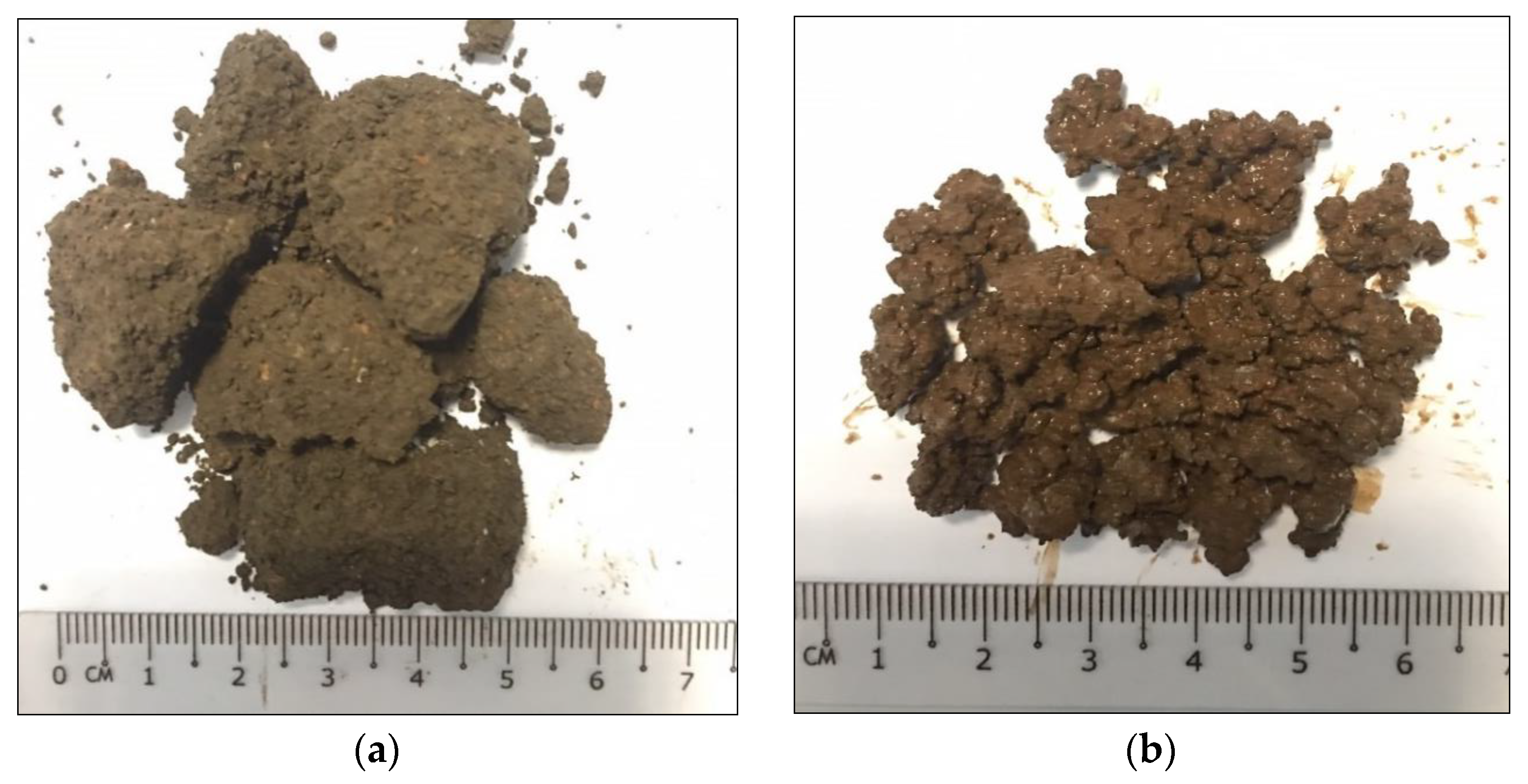
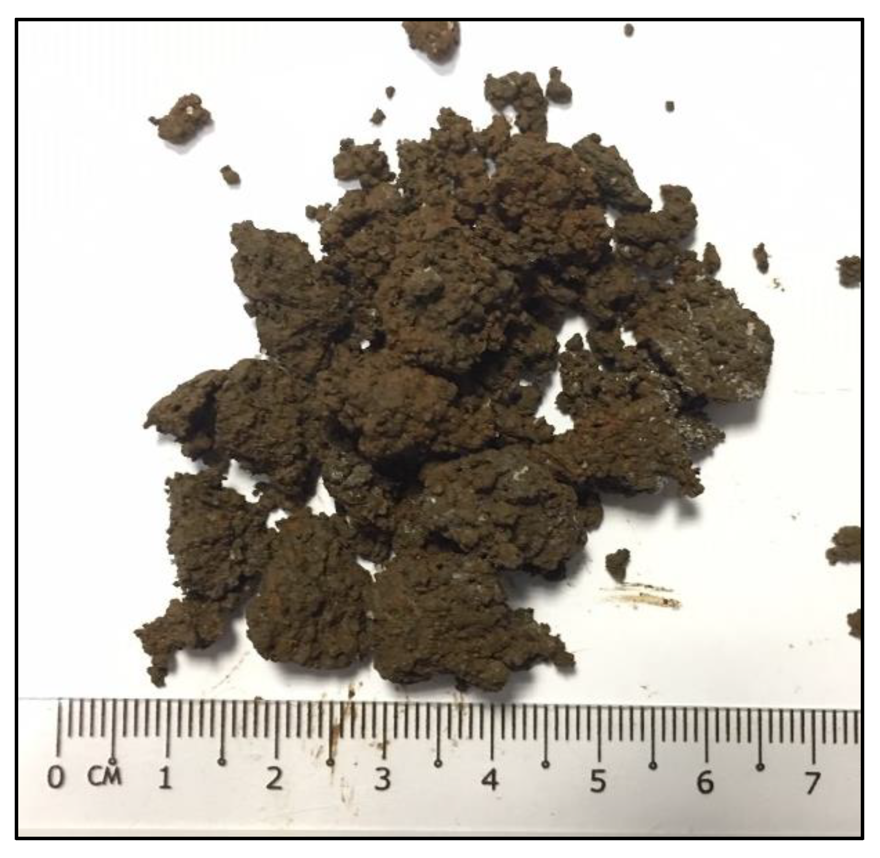
2.2. Composite Sample Preparation

The composite of sewage sludge (SS) and red gypsum (RG) at a weight ratio of 1:1 [31] was used as a sample in the column study. The selection of the composition was based on the result obtained from the previous study [31], in which 1SS:1RG is the ideal mix ratio to have a Ca:Si composition closest to 3 with comparable performance to that of soil as landfill cover. At other ratios, the lesser content of Ca or Si becomes the limiting factor for forming CSH gel, resulting in poorer performance. SS was directly taken from the sludge dewatering conveyor at Kuching Centralized Wastewater Treatment Plant, Sarawak, Malaysia, while the titanium dioxide factory in Telok Kalong, Terengganu, Malaysia, supplied RG. Both materials were oven-dried at 103 °C for 72 h and pulverized to granules no larger than 2 mm using a mortar and pestle. Samples were set up by mixing equal weights of dried SS and RG (1:1) in a Hobart A200-BHE mixer for 10 min at 60 rpm.

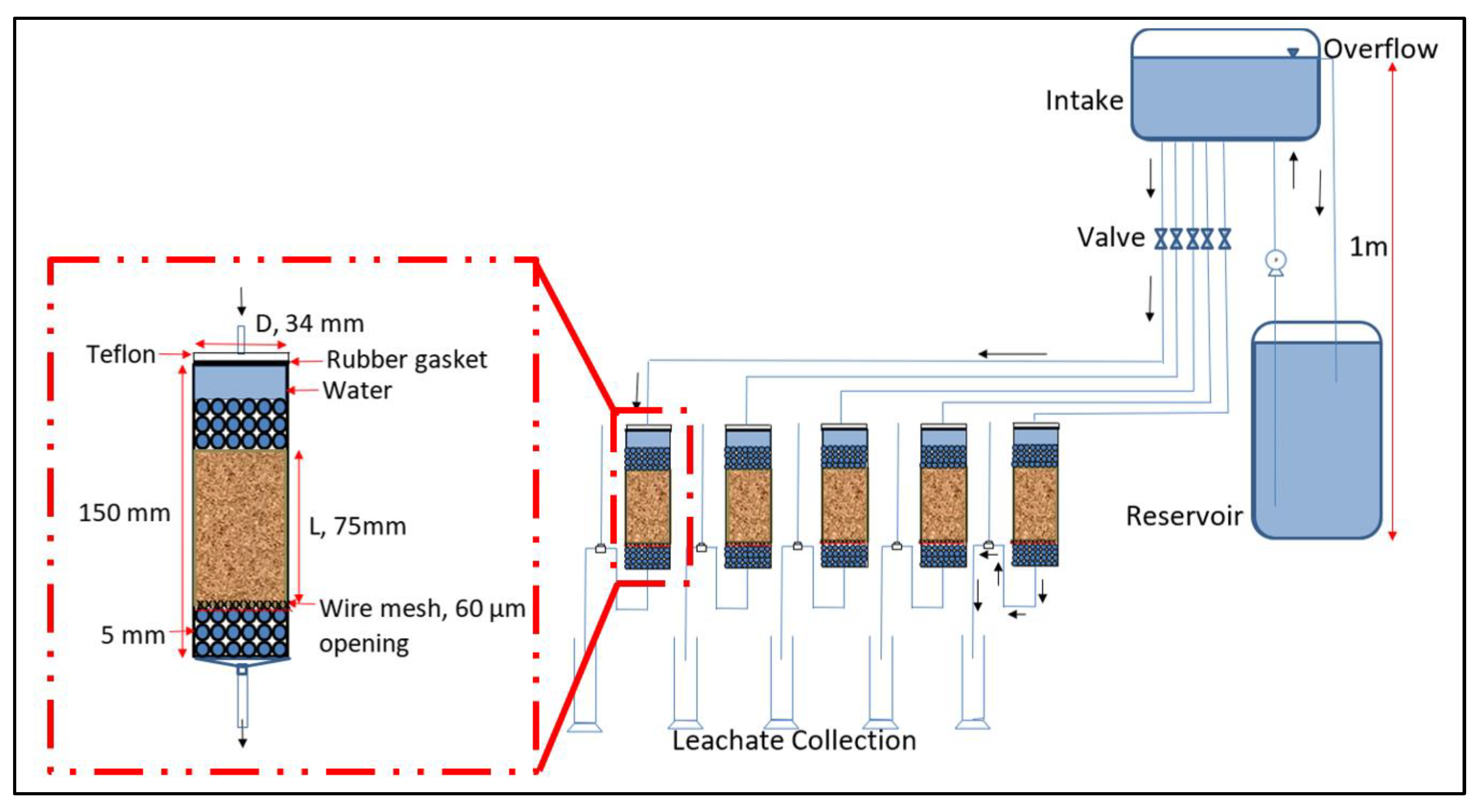
2.3. Hydraulic Conductivity Using Column Test

Hydraulic conductivity tests were carried out in a series of columns using the constant head technique for 180 days (Figure 1). The column set-up was identical to that of [23]. Each sample was compacted to about 75 mm thick using a caulk gun and sandwiched between two 25 mm thick layers of 5 mm glass beads. The mass of samples was set based on the predetermined dry densities of 0.64, 0.75, 0.80, 0.86 and 0.91 g/cm3, corresponding to 60, 70, 75, 80, and 85% compaction. Every interface between layers was lined using a 60 µm stainless steel mesh. The distilled water was then filled into the column, which was sealed with a rubber gasket, Teflon, and silicone (inset of Figure 1). The hydraulic gradient was fixed throughout the experiment by maintaining the water level in the constant head tank. The leachate was sampled at the base of each column on pre-determined days: 1, 3, 7, 14, 28, 42, 56, 75, 90, 120, 150 and 180. The hydraulic conductivity was calculated based on the volume of leachate collected, V, within a specified time interval, t, length of the sample, L, and cross-sectional area, A, using Equation (1).
k c m s = V A t L h

2.4. Leachate Sample Analysis

2.4.1. PH

PH testing was conducted in accordance with the APHA 4500-H B method. All leachate samples were tested immediately using a Fisher Scientific Accumet AB150 pH benchtop meter.

2.4.2. Chemical Oxygen Demand (COD)

The COD test was performed using standard method 5220 C, closed reflux titrimetric method [32]. For leachate and blank samples, 2.5 mL of leachate and distilled water were added to 1.5 mL of potassium dichromate and 3 mL of sulphuric acid reagent, respectively. The samples were heated in a HACH, DRB 200 COD digester at 150 °C for 2 h. A few drops of ferroin indicator were then added to the samples, where the blank ones were titrated using 0.1 N ferrous ammonium sulphate (FAS) solution until the solution turned from blue-green to reddish-brown.

2.4.3. Heavy Metals

Ion conductive plasma (ICP-OES, Varian, Australia) was used to determine the concentrations of iron (Fe), copper (Cu) and zinc (Zn). The leachate collected from the columns was first acidified with a few drops of nitric acid and refrigerated at 4 °C for storage purposes. The samples were next filtered using a 0.45 μm glass microfibre filter before analysis to minimise colour interference and risk of tube clogging. The samples were then diluted 10 times using distilled water to ensure that the measurement of concentration was within the linear calibration range while maintaining the condition of ICP.

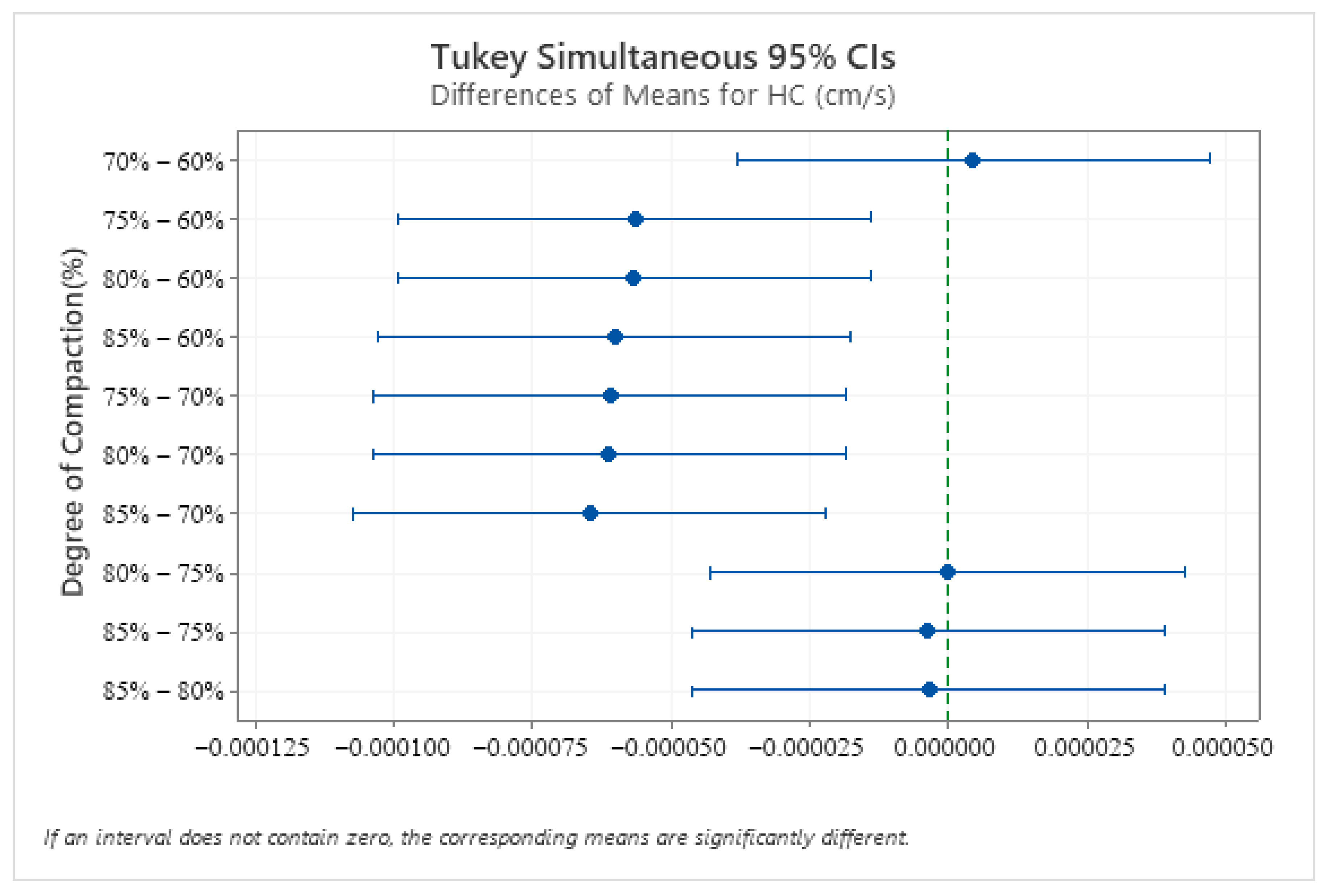
2.5. Statistical Analysis

The statistical analysis was carried out using Minitab 17 software [33]. Regression analysis was used to study the relationship and correlation of the parameter of interest (degree of compaction and hydraulic conductivity). The fitted line plot with an R squared of more than 99% and a P value of less than 0.05 indicates a strong correlation between parameters. Tukey pairwise comparison was used to assess the effects of compaction on the measured variables. The P-value of less than 0.05 shows the significant effect of compaction on the measured variables.

3. Results

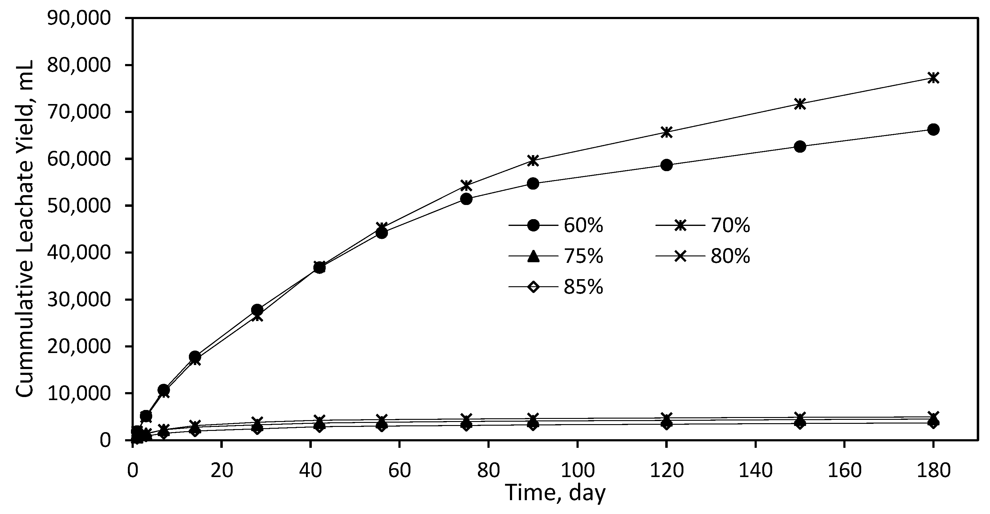
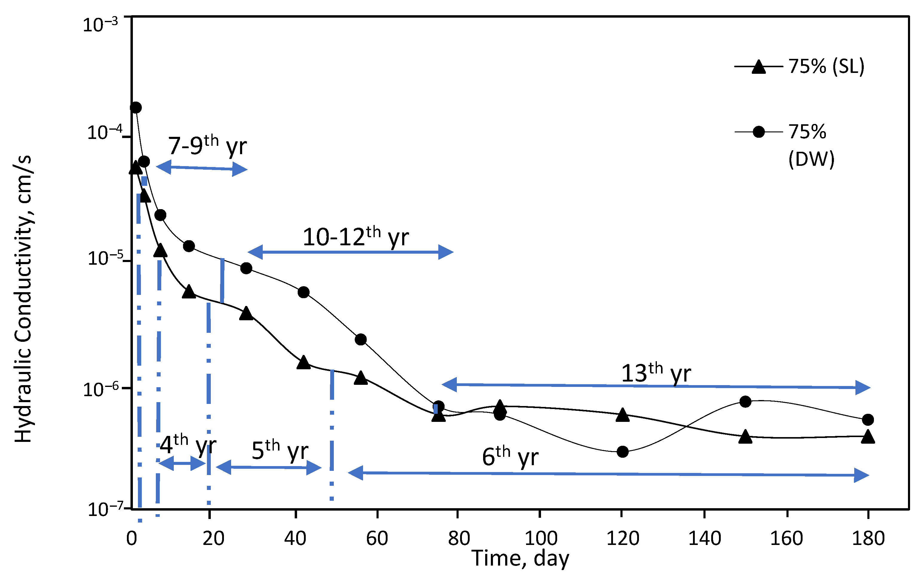
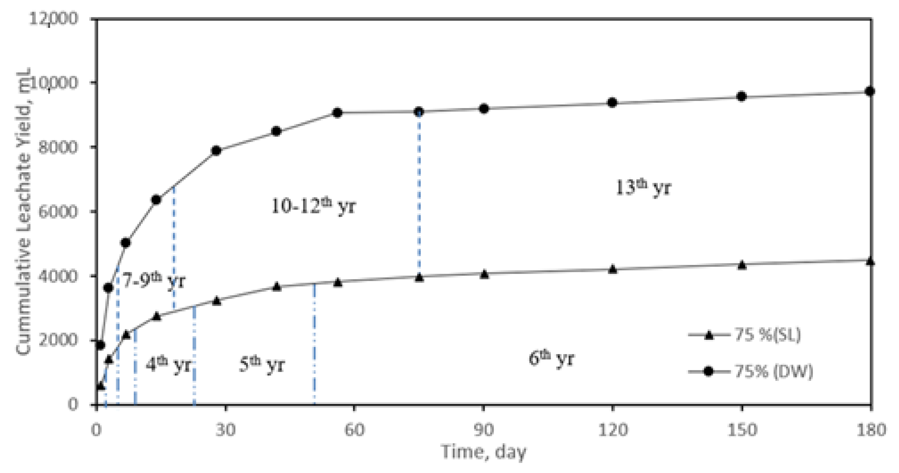
3.1. Hydraulic Conductivity and Leachate Yield

The effects of compaction on the hydraulic conductivity of samples were examined by flowing synthetic leachate through columns for 180 days. The hydraulic conductivity varied significantly in samples compacted up to 70% and those with values of 75% or greater (Figure 2). The result shows that the degree of compaction has a direct effect on the initial porosity and hydraulic conductivity. For samples compacted by more than 75%, the low porosity contributes to the slow velocity, which allows the formation of calcium silicate hydrate (CSH) gel. As for samples compacted up to 70%, they contain more pores, which lead to a fast flow, thereby inhibiting the formation of CSH gel. The significance of compaction on hydraulic conductivity was supported by the grouping information using the Tukey method, where the compacted composite can be grouped into two different groups, A and B (Table 2 and Figure 3). In this analysis, samples compacted at 70% and 75% were then used as the referenced sets to represent the hydraulic conductivity response. In particular, the hydraulic conductivity reduced in a first-order manner for samples compacted at 70%, resulting in a reduction by one order of magnitude (10−4 to 10−5 cm/s) after 180 days. Samples compacted at 75% showed a second-order decrease in hydraulic conductivity, resulting in a 2-fold reduction in magnitude (10−5 to 10−7 cm/s). The variation of hydraulic conductivity was more pronounced on the leachate yield, as shown in Figure 3.
The hydraulic conductivity ranging from 10−4 to 10−5 cm/s for a 70% compacted sample yielded 77,284 mL of leachate, as shown in Figure 4, while it was between 10−5 and 10−7 cm/s for a sample compacted at 75%, resulting in 4560 mL leachate over 180 days. The difference of two orders of magnitude in hydraulic conductivity between samples compacted at 70% and 75% (Figure 2) resulted in a reduction in leachate yield of up to 90% over 180 days. The total leachates yielded for 70% and 75% compaction over 180 days corresponding to average linear velocities of 13.67 m/s and 0.8 m/s, respectively. The total leachate achieved by samples compacted at 75% in 180 days was yielded by that at 70% in three days (Figure 4). The significant reduction in leachate yield helps to regulate the leachate quality, which facilitates the leachate management for compliance with the discharge requirements by EQA 1974 [7]. Therefore, it is worthwhile to recognise that samples compacted at 75% or more are specifically favourable for use in tropical countries where precipitation is relatively high, i.e., >3500 mm/year.
The drop in hydraulic conductivity is attributed to the reduction in porosity; the porosity of samples compacted at 70 and 75% reduced from 60 to 52% and from 57 to 40%, respectively, in 180 days. The porosity of samples was estimated based on the correlation between the degree of compaction and porosity developed in [23]. The initial rapid reduction in hydraulic conductivity within the first 14 days for samples compacted at 75% or more (Figure 2) was due to the particle rearrangement as the leachate percolated through the samples.
Rosli et al. [23] observed that when the mixture was percolated using distilled water, there existed a hydration reaction based on the formation of CSH and CH identified from SEM and EDX. From this finding, the percolation of leachate through the mixture is also expected to form CSH, which is proven by the formation of the lump with an average size of 25 to 30 mm observed in samples extracted from the column after 180 days (Figure 5a). This contributed to the slow velocity, as CSH had occupied the pores and interlocked the particles in the mixture. The reduction in porosity beyond 14 days was attributed to the further formation of CSH and entrapment of precipitated heavy metals due to an increase in pH (which is discussed further in Section 3.2.1).
Figure 5a displays that the extracted sample from the 75% compacted column is relatively dry compared to that of 70% as the water content was utilized for the hydration process. Samples compacted up to 70% consist of moist and loose agglomeration of fine granules with an average size of 5 to 10 mm (Figure 5b), indicating the formation of CSH gel was inhibited by the relatively fast flow, which transported the Ca2+ ion, and in turn contributed to voids’ occurrence (Figure 5b). The relatively fast flow suggests that the slower reduction in hydraulic conductivity is predominantly affected by particle rearrangement.
Therefore, 75% compaction is significant in limiting the velocity to allow the formation of CSH to provide the required strength for the landfill operation.

3.2. Leachate Quality

The leachate quality was monitored at pre-determined time intervals for pH, Cu, Fe and Zn to address the response of compacted samples towards synthetic leachate in terms of the immobilisation of metals. The results of leachate quality after 180 days are summarised in Table 3, and the details of the result analysis are further discussed in the following subsection. The quality of the leachate flowing through the composite sample varied based on the degree of compaction, similar to that of hydraulic conductivity.

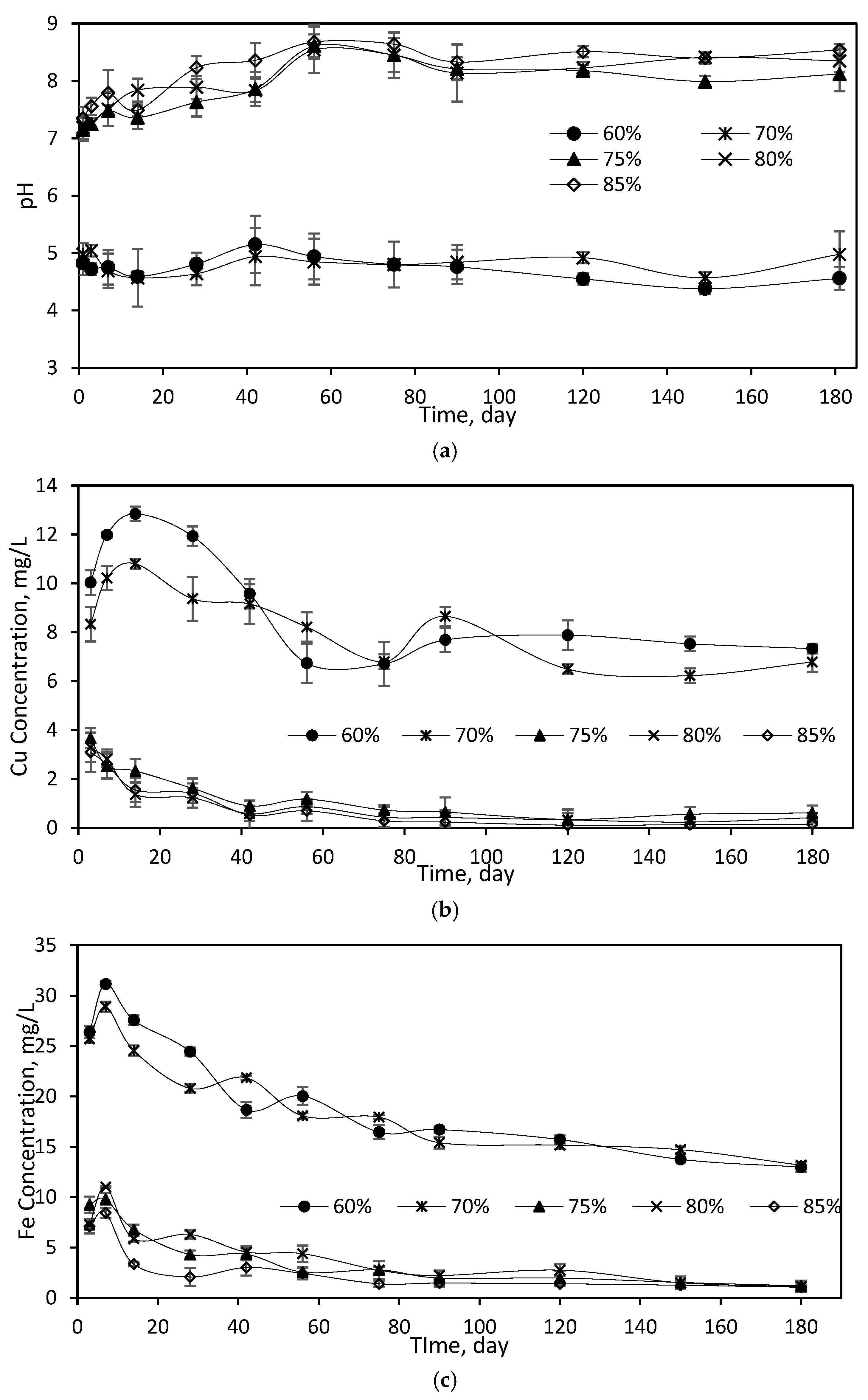
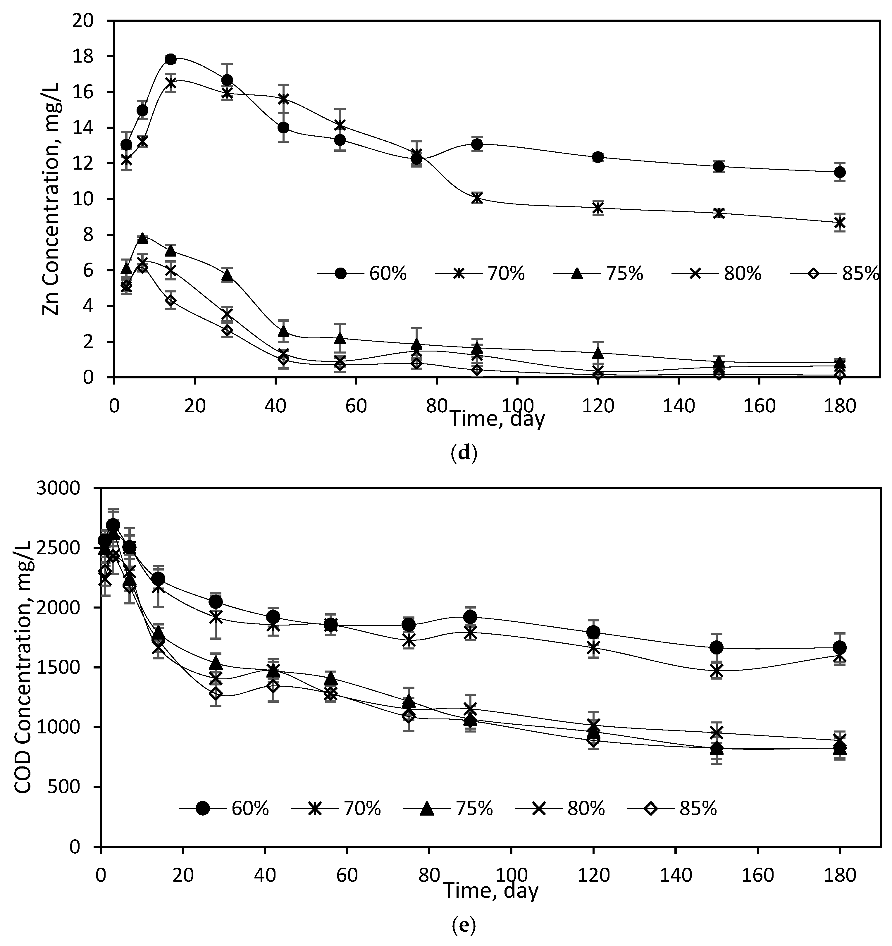
3.2.1. PH, Heavy Metals and COD

Following similar trends observed in Figure 2 and Figure 3, the leachate flowing through samples shows a significant variation of pH between samples compacted up to 70% and more than 75%. It can be seen in Table 3 that the pH of leachate flowing through samples compacted at 70% is 4.98 ± 0.4, similar to the pH of the feed solution. The low pH and relatively fast velocity (13.67 m/s) enhance the solubility and mobility of cations, including metals [34,35]. Consequently, Ca2+ ions are transported by leachate prior to the formation of CSH gel [36] and the soluble metals flow through the pores of samples, which have a relatively greater porosity (Figure 2 and Figure 4). Consequently, the concentration of Cu, Fe and Zn in leachate flowing through samples compacted at 70% is 10-fold higher than that of samples compacted at 75% and 2-fold higher for COD (Figure 6).
The pH of leachate flowing through the samples compacted at 75% is 8.12 ± 0.3 (Table 3). The increase in pH to circa 8 due to the hydration of CSH [37] promoted heavy metal precipitation [35,38], which was consequently entrapped among the pores, and thereby the interlocking of CSH (chemical clogging) as shown in Figure 5a. This phenomenon contributes to the further reduction in porosity and low hydraulic conductivity and therefore reduces the heavy metal concentration in leachate. Due to the entrapment of heavy metal precipitation, the sample compacted at 75% shows a reduction in COD concentration by 68%, whereas in those compacted at 70% it reduces by 38% (Table 3).
Therefore, it is significant to compact the sample up to 75% to allow the hydration of CSH and entrap the precipitate heavy metals, which consequently reduces the strength of leachate for treatment.

3.3. Effects of Feed Solution on the Leaching Behaviour

This section examines the effects of feed solution (distilled water, DW, and synthetic leachate, SL) on the leaching behaviour by comparing the hydraulic conductivity and formation of lumps for composites compacted at 75%. The hydraulic conductivity can be observed to be reducing faster by about an order of magnitude when flowing synthetic leachate through the sample, compared to that of distilled water (Figure 7). This difference is attributed to concentration gradient and initial fluid velocity, both of which affect the hydration of CSH. The concentration gradient between composite and synthetic leachate is less than that for distilled water, which results in a slower diffusion rate of Ca and Si into leachate. In addition, the initial fluid velocity for synthetic leachate was 3-fold slower than that of distilled water, thus promoting the hydration of CSH, which formed larger lumps of 25 to 30 mm (Figure 5a) compared to those between 5 and 15 mm for distilled water (Figure 8). The hydration of CSH increased the pH of leachate, resulting in the precipitation of heavy metals, which were subsequently entrapped within the interlocking of CSH (Section 3.2.1), thus contributing to a further reduction in porosity and hydraulic conductivity.
The significance of synthetic leachate in reducing hydraulic conductivity faster than distilled water was more pronounced in the leachate yield as shown in Figure 9. The leachate yield using distilled water was 9712 mL and a reduction in leachate yield circa 50% was achieved when flowing synthetic leachate through composite. The study provides the means of a continuous infiltration of fluid (distilled water or synthetic leachate), which expedites the leaching process through the composites.
To put things into a practical perspective, the design rainfall for this study was 4000 mm/year for Sarawak, Malaysia [39]. Assuming only 20% of the total annual rainfall infiltrates the composite [40], 800 mm/year of rainfall is expected to pass through the soil cover every year. The amount of leachate collected in this study can then be divided proportionally to the equivalent rainfall amount of 800 mm/year. Hence, the leachate yield (Figure 9) and hydraulic conductivity (Figure 7) in this study correspond to 6 and 13 years of equivalent rainfall infiltration into the composites, using synthetic leachate and distilled water, respectively.

3.4. Recommended Degree of Compaction

This study reveals that a minimum of 75% compaction exhibits a decreased hydraulic conductivity by two orders of magnitude and a leachate yield reduction of up to 90%, which are favourable for intermediate landfill cover application in a tropical climate. In addition, 75% of compaction is able to limit the migration of leachate constituents, resulting in a lower concentration of leachate for treatment prior to discharge. However, based on an earlier study using distilled water [23], 75% compaction achieved a compressive strength of 331 kPa, which does not meet the minimum required strength of 345 kPa for landfill site stability [41,42]. Therefore, a minimum of 80% compaction is recommended by this study in order to fulfil all the requirements for landfill applications.

4. Conclusions

This study presented the leaching responses of sewage sludge and red gypsum composite as intermediate landfill cover through the effects of compaction towards long-term exposure to synthetic leachate. From the examined range, the significance of compaction is statistically obtained, such that compacting composite at 75% can help to reduce leachate yield by circa 90%. The reduction in hydraulic conductivity throughout the 180 days is due to the particle rearrangement, formation of CSH, and entrapment of precipitated heavy metals, which occupy the pores in the mixtures. It was found that the hydraulic conductivity reduces in a second-order manner and stabilises as early as 75 days after compaction. In addition, the obtained results from the leachate quality reveal that compacting composite at 75% also can retain a significant amount of leachate constituents from flowing into the leachate treatment plant, which favours leachate management at landfills. Nevertheless, a minimum of 80% compaction is recommended as it fulfils all the requirements of landfill cover. This study, therefore, provides a useful reference for managing intermediate landfill cover at landfills.

Author Contributions

Conceptualization, H.A.A.; Data curation, N.A.R.; Formal analysis, N.A.R., A.B.H.K. and L.L.P.L.; Funding acquisition, H.A.A.; Investigation, N.A.R., A.B.H.K. and L.L.P.L.; Methodology, N.A.R., H.A.A., A.B.H.K., L.L.P.L. and M.H.Z.; Project administration, H.A.A.; Resources, H.A.A.; Software, N.A.R., A.B.H.K. and M.H.Z.; Supervision, H.A.A.; Validation, N.A.R.; Visualization, N.A.R. and A.B.H.K.; Writing—original draft, N.A.R.; Writing—review and editing, N.A.R., H.A.A., A.B.H.K., L.L.P.L. and M.H.Z. All authors have read and agreed to the published version of the manuscript.

Funding

This research was funded by the Fundamental Research Grant Scheme (FRGS), grant number No. 203.PAWAM.6071412 and GL/F02/USM/01/2019.

Institutional Review Board Statement

Not applicable.

Informed Consent Statement

Not applicable.

Data Availability Statement

Data is contained within the article.

Acknowledgments

The authors would like to thank the Ministry of Higher Education, Malaysia (Kementerian Pendidikan Tinggi, KPT) for funding this work through the Fundamental Research Grant Scheme, No. 203.PAWAM.6071412 and GL/F02/USM/01/2019. The authors also extend gratefulness to Universiti Sains Malaysia (USM) and Universiti Malaysia Sarawak (UNIMAS) for the facilities provided for the study. Furthermore, the authors acknowledge the support given by the School of Materials and Mineral Resources Engineering, USM for access to the use of special equipment.

Conflicts of Interest

The authors declare no conflict of interest.

References

  1. Fuller, J.M. Landfill cap designs using geosynthetic clay liners. In Geosynthetic Clay Liners, Proceedings of the International Symposium, Nuremberg, Germany, 16–17 April 2002; CRC Press: London, UK, 2020; p. 129. [Google Scholar] [CrossRef]
  2. Zhang, D.; Wang, J.; Chen, C. Gas and liquid permeability in the variably saturated compacted loess used as an earthen final cover material in landfills. Waste Manag. 2020, 105, 49–60. [Google Scholar] [CrossRef] [PubMed]
  3. NSWEPA. Draft Environmental Guidelines: Solid Waste Landfills, 2nd ed.; NSW EPA: Sydney, Australia, 2015. [Google Scholar]
  4. Fan, X.; Zhu, W.; Qian, Y.; Wu, S.; Shu, S.; Lin, N. Increasing the Hydraulic Conductivity of Solidified Sewage Sludge for Use as Temporary Landfill Cover. Adv. Civ. Eng. 2019, 2019, 8163563. [Google Scholar] [CrossRef] [Green Version]
  5. Vinitha, V.N.; Latha, P.; Jaya, V. Permeability study of modified forms of sewage sludge suitable for temporary landfill cover material. In Recent Advances in Materials, Mechanics and Management, Proceedings of the 3rd International Conference on Materials, Mechanics and Management (IMMM 2017), Trivandrum, Kerala, India, 13–15 July 2017; CRC Press: London, UK, 2019; p. 183. [Google Scholar] [CrossRef]
  6. He, J.; Li, F.; Li, Y.; Cui, X.-L. Modified sewage sludge as temporary landfill cover material. Water Sci. Eng. 2015, 8, 257–262. [Google Scholar] [CrossRef] [Green Version]
  7. ILBS. Environmental Quality Act 1974 (Act 127), Regulations, Rules & Orders: Environmental Quality (Control of Pollution from Solid Waste Transfer Station and Landfill) Regulations 2009 (as at 10th June 2019); International Law Book Services: Kuala Lumpur, Malaysia, 2019. [Google Scholar]
  8. Zhang, P.; Zhang, G.; Wang, W. Ultrasonic treatment of biological sludge: Floc disintegration, cell lysis and inactivation. Bioresour. Technol. 2007, 98, 207–210. [Google Scholar] [CrossRef]
  9. Balkaya, M. Assessment of the geotechnical aspect of the use of paper mill sludge as landfill cover and bottom liner material. Desalination Water Treat. 2019, 172, 70–77. [Google Scholar] [CrossRef]
  10. Sharma, A.; Kaushik, M.K.; Naval, S. Present Status of MSW Disposal in Jalandhar and Suitability of Tire Derived Aggregates as a Drainage Material in Cover System of Landfill. J. Innov. Res. Sci. Eng. Technol. 2016, 5, 1111–1118. [Google Scholar] [CrossRef]
  11. Inazumi, S. Waste Sludge Barrier for Landfill Cover System. Doctoral Dissertation, Kyoto University, Kyoto, Japan, 2003. [Google Scholar] [CrossRef]
  12. Durak, S.G.; Özçoban, M.Ş.; Balcıoğlu, E.B.; Salmanli, Ö.M.; Demirkol, G.; Tüfekci, N. The Effect of Leachate on the Compacted and Consolidated Clay Soils. Eurasian J. Environ. Res. 2017, 1, 36–47. [Google Scholar]
  13. Dąbska, A. Hydraulic Conductivity of Compacted Lime-Softening Sludge Used as Landfill Liners. Water Air Soil Pollut. 2019, 230, 280. [Google Scholar] [CrossRef] [Green Version]
  14. Ozcoban, M.S.; Cetinkaya, N.; Celik, S.O.; Demirkol, G.T.; Cansiz, V.; Tufekci, N. Hydraulic conductivity and removal rate of compacted clays permeated with landfill leachate. Desalination Water Treat. 2013, 51, 6148–6157. [Google Scholar] [CrossRef]
  15. Edil, T.B.; Sandstrom, L.K.; Berthouex, P.M. Interaction of Inorganic Leachate with Compacted Pozzolanic Fly Ash. J. Geotech. Eng. 1992, 118, 1410–1430. [Google Scholar] [CrossRef]
  16. Safari, E. Preliminary Assessment of Proposed Soil Liner Compatibility with Leachate at New Landfill of Tehran. J. Biol. Sci. 2006, 6, 324–330. [Google Scholar] [CrossRef] [Green Version]
  17. Wang, G.; Gao, Y.; Tang, Y. Research on the mechanism for chemical clogging and its effect on the stability of tailing dam. Bulg. Chem. Commun. 2017, 49, 228–233. [Google Scholar]
  18. Francisca, F.M.; Glatstein, D.A. Long term hydraulic conductivity of compacted soils permeated with landfill leachate. Appl. Clay Sci. 2010, 49, 187–193. [Google Scholar] [CrossRef]
  19. VanGulck, J.F.; Rowe, R.K. Evolution of clog formation with time in columns permeated with synthetic landfill leachate. J. Contam. Hydrol. 2004, 75, 115–139. [Google Scholar] [CrossRef] [PubMed]
  20. Sunil, B.M.; Shrihari, S.; Nayak, S. Soil-leachate interaction and their effects on hydraulic conductivity and compaction characteristics. In Proceedings of the 12th International Conference on Computer Methods and Advances in Geomechanics, Goa, India, 1–6 October 2008; Volume 3, pp. 2380–2386. [Google Scholar]
  21. Ray, S.; Mishra, A.K.; Kalamdhad, A.S. Hydraulic performance, consolidation characteristics and shear strength analysis of bentonites in the presence of fly-ash, sewage sludge and paper-mill leachates for landfill application. J. Environ. Manag. 2022, 302, 113977. [Google Scholar] [CrossRef] [PubMed]
  22. Shang, K. Mechanical Characteristics and Micro-Mechanism of Modified Dredged Sludge Based on Calcium-Containing Solid Waste Used as Landfill Cover Materials. Processes 2022, 10, 451. [Google Scholar] [CrossRef]
  23. Rosli, N.A.; Aziz, H.A.; Selamat, M.R.; Lim, L.L.P.; Zawawi, M.H. Effect of compaction on physical properties of a sewage sludge and red gypsum mixture as intermediate landfill cover. Constr. Build. Mater. 2021, 289, 123153. [Google Scholar] [CrossRef]
  24. Zakaria, S.N.F.; Aziz, H.A. Characteristic of leachate at Alor Pongsu Landfill Site, Perak, Malaysia: A comparative study. IOP Conf. Ser. Earth Environ. Sci. 2018, 140, 012013. [Google Scholar] [CrossRef] [Green Version]
  25. Yong, Z.J. Papan Landfill Leachate Treatment Using a Sequencing Batch Reactor and Coagulation. Doctoral Dissertation, UTAR, Perak, Malaysia, 2017. [Google Scholar]
  26. Mohamad, M.; Abustan, I.; Samuding, K.; Mohamad, A.; Mohamad, N. Enhancement of Landfill Daily Cover in Minimizing the Migration of Heavy Metals in Landfill Leachate by Using Natural Soil, Pressmud Empty Fruit Bunch (EFB) in Pulau Burung Landfill. Int. J. Adv. Eng. Manag. Sci. 2017, 3, 37–47. [Google Scholar]
  27. Aziz, S.Q.; Aziz, H.A.; Yusoff, M.S.; Bashir, M.J.; Umar, M. Leachate characterization in semi-aerobic and anaerobic sanitary landfills: A comparative study. J. Environ. Manag. 2010, 91, 2608–2614. [Google Scholar] [CrossRef]
  28. Zerrouqi, Z.; Tazi, M.R.; Chafi, A.; Zerrouqi, A. Impact of Sewage Sludge Leaching on Soil Constituents and Quality. Environ. Res. Eng. Manag. 2020, 76, 87–96. [Google Scholar] [CrossRef]
  29. Geng, H.; Xu, Y.; Zheng, L.; Gong, H.; Dai, L.; Dai, X. An overview of removing heavy metals from sewage sludge: Achievements and perspectives. Environ. Pollut. 2020, 266, 115375. [Google Scholar] [CrossRef] [PubMed]
  30. Mohamed, B.A.; Ruan, R.; Bilal, M.; Khan, N.A.; Awasthi, M.K.; Amer, M.A.; Leng, L.; Hamouda, M.A.; Vo, D.N.; Li, J. Co-pyrolysis of sewage sludge and biomass for stabilizing heavy metals and reducing biochar toxicity: A review. Environ. Chem. Lett. 2022, 1–20. [Google Scholar] [CrossRef]
  31. Rosli, N.A.B.; Aziz, H.A.; Selamat, M.R.; Lim, L.L.P. A mixture of sewage sludge and red gypsum as an alternative material for temporary landfill cover. J. Environ. Manag. 2020, 263, 110420. [Google Scholar] [CrossRef]
  32. APHA; WEF. Standard Methods for the Examination of Water and Wastewater, 21st ed.; American Public Health Association: Washington, DC, USA, 2005; pp. 258–259. [Google Scholar]
  33. Minitab Inc. Minitab (Version 17), 17th ed.; Minitab Statistical Software; State College: Centre County, PA, USA, 2015. [Google Scholar]
  34. Söderberg, T.U.; Kleja, D.B.; Åström, M.; Jarsjö, J.; Fröberg, M.; Svensson, A.; Augustsson, A. Metal solubility and transport at a contaminated landfill site–From the source zone into the groundwater. Sci. Total Environ. 2019, 668, 1064–1076. [Google Scholar] [CrossRef]
  35. Ayres, D.M.; Davis, A.P.; Gietka, P.M. Removing heavy metals from wastewater. Eng. Res. Cent. Rep. 1994, 90, 1–21. [Google Scholar]
  36. Fang, H.Y. Soil Stabilization and Grouting. Foundation Engineering Handbook; Springer Science & Business Media: New York, NY, USA, 2013. [Google Scholar]
  37. Šiler, P.; Kolářová, I.; Sehnal, T.; Másilko, J.; Opravil, T. The Determination of the Influence of pH Value of Curing Conditions on Portland Cement Hydration. Procedia Eng. 2016, 151, 10–17. [Google Scholar] [CrossRef] [Green Version]
  38. Kjeldsen, P.; Barlaz, M.A.; Rooker, A.P.; Baun, A.; Ledin, A.; Christensen, T.H. Present and Long-Term Composition of MSW Landfill Leachate: A Review. Crit. Rev. Environ. Sci. Technol. 2002, 32, 297–336. [Google Scholar] [CrossRef]
  39. Malaysian Meteorological Department. Determination of Z-R Relationship and Inundation Analysis for Kuantan River Basin. 2017. Available online: https://www.met.gov.my/data/research/researchpapers/2017/researchpaper_201702.pdf (accessed on 18 April 2019).
  40. Markovič, G.; Zeleňáková, M.; Káposztásová, D.; Hudáková, G. Rainwater infiltration in the urban areas. WIT Trans. Ecol. Environ. 2014, 181, 313–320. [Google Scholar] [CrossRef] [Green Version]
  41. Phenrat, T.; Marhaba, T.F.; Rachakornkij, M. XRD and unconfined compressive strength study for a qualitative examination of calcium–arsenic compounds retardation of cement hydration in solidified/stabilized arsenic–iron hydroxide sludge. J. Environ. Eng. 2007, 133, 595–607. [Google Scholar] [CrossRef]
  42. Wang, Y.X.; Ding, J.W.; Hong, Z.S. Compressive Strength Characteristics and Volume Change of Sewage Sludge Matrices Solidified by a New Binder. Adv. Mater. Res. 2011, 255–260, 2819–2823. [Google Scholar] [CrossRef]
Figure 1. Experimental set-up of column test and packing of samples in column (L = 0.075 m, A = 9.08 cm2, h = 1 m, hydraulic gradient, i = 13.3).
Sustainability 15 04229 g001
Figure 2. Hydraulic conductivity of samples at various degrees of compaction.
Sustainability 15 04229 g002
Figure 3. Effect of degree of compaction on hydraulic conductivity using Tukey method: differences of means.
Sustainability 15 04229 g003
Figure 4. Effect of degree of compaction on leachate yield.
Sustainability 15 04229 g004
Figure 5. Sample extracted from (a) 75% compaction consisting of dry lump sizing between 25 and 30 mm and (b) 70% compaction in moist and agglomerated granules with sizes ranging between 5.0 and 10 mm.
Sustainability 15 04229 g005
Figure 6. Variation of the leachate concentration (a) pH (b) Cu (c) Fe (d) Zn and (e) COD.
Sustainability 15 04229 g006aSustainability 15 04229 g006b
Figure 7. The reduction in hydraulic conductivity is faster when synthetic leachate is flowed through the composite. Corresponding to the rainfall infiltration, the composites require about 6 and 13 years to achieve hydraulic conductivity of 10−7 cm/s when flowing synthetic leachate and distilled water, respectively.
Sustainability 15 04229 g007
Figure 8. Formation of the lump for sample feed with distilled water, with lump sizes ranging between 5 to 15 mm.
Sustainability 15 04229 g008
Figure 9. Initial fluid velocity for synthetic leachate is slower than that of distilled water with a 50% reduction in the cumulative leachate yield when synthetic leachate is flowing through the composite in the former. The leachate yields of 9712 and 4560 mL for distilled water and synthetic leachate correspond to 13 and 6 years of rainfall infiltration into the composite, respectively.
Sustainability 15 04229 g009
Table 1. Designed and measured solution of synthetic leachate.
ElementChemical ProductDesigned (mg/L)Measured Feed Solution (mg/L)Young Leachate (Acid Phase Formation)
Stock SolutionFeed Solution
pH---4.83<6.5
CODPotassium Hydrogen Phthalate (C8H5KO4)50,00050005210>10,000
NH3-NAmmonium Nitrate (NH4-NO3)10,0001000670<400
CuCopper (II) Chloride Anhydrous
(CuCl2)
1001011.65>2
FeIron (III) Chloride Hexahydrate (FeCl3·6H2O)2502525.37>2
ZnZinc Sulphate Heptahydrate (ZnSO4·7H2O)1001013.7>2
Table 2. Effect of degree of compaction on hydraulic conductivity using Tukey method: grouping information.
Degree of
Compaction (%)
NMeanGrouping
70%120.0000711A
60%120.0000667A
75%120.0000102B
80%120.0000102B
85%120.0000067B
Table 3. Comparison of leachate quality from variously compacted samples after 180 days with feed solution and typical raw leachate.
ParameterTypical Raw Leachate [25]Feed SolutionDegree of Compaction (%)
6070758085
Leachate Yield (mL)--66,26477,284449949553677
pH7.8–8.394.834.56 ± 0.24.98 ± 0.48.12 ± 0.38.35 ± 0.28.54 ± 0.1
COD (mg/L)1929–497552101664 ± 881600 ± 78824 ± 95888 ± 75824 ± 85
Cu (mg/L)0.095–1311.657.3 ± 0.46.8 ± 0.40.6 ± 0.20.4 ± 0.40.1 ± 0.3
Fe (mg/L)3.61–23.225.413 ± 0.313.2 ± 0.21.2 ± 0.41.1 ± 0.41.1 ± 0.4
Zn (mg/L)0.24–7.513.711.5 ± 0.48.7 ± 0.30.8 ± 0.40.6 ± 0.20.1 ± 0.4
Disclaimer/Publisher’s Note: The statements, opinions and data contained in all publications are solely those of the individual author(s) and contributor(s) and not of MDPI and/or the editor(s). MDPI and/or the editor(s) disclaim responsibility for any injury to people or property resulting from any ideas, methods, instructions or products referred to in the content.

