
Dynamic Analysis of a Combined Spiral Bevel Gear and Planetary Gear Set in a Bucket Elevator with High Power Density
Abstract
:1. Introduction
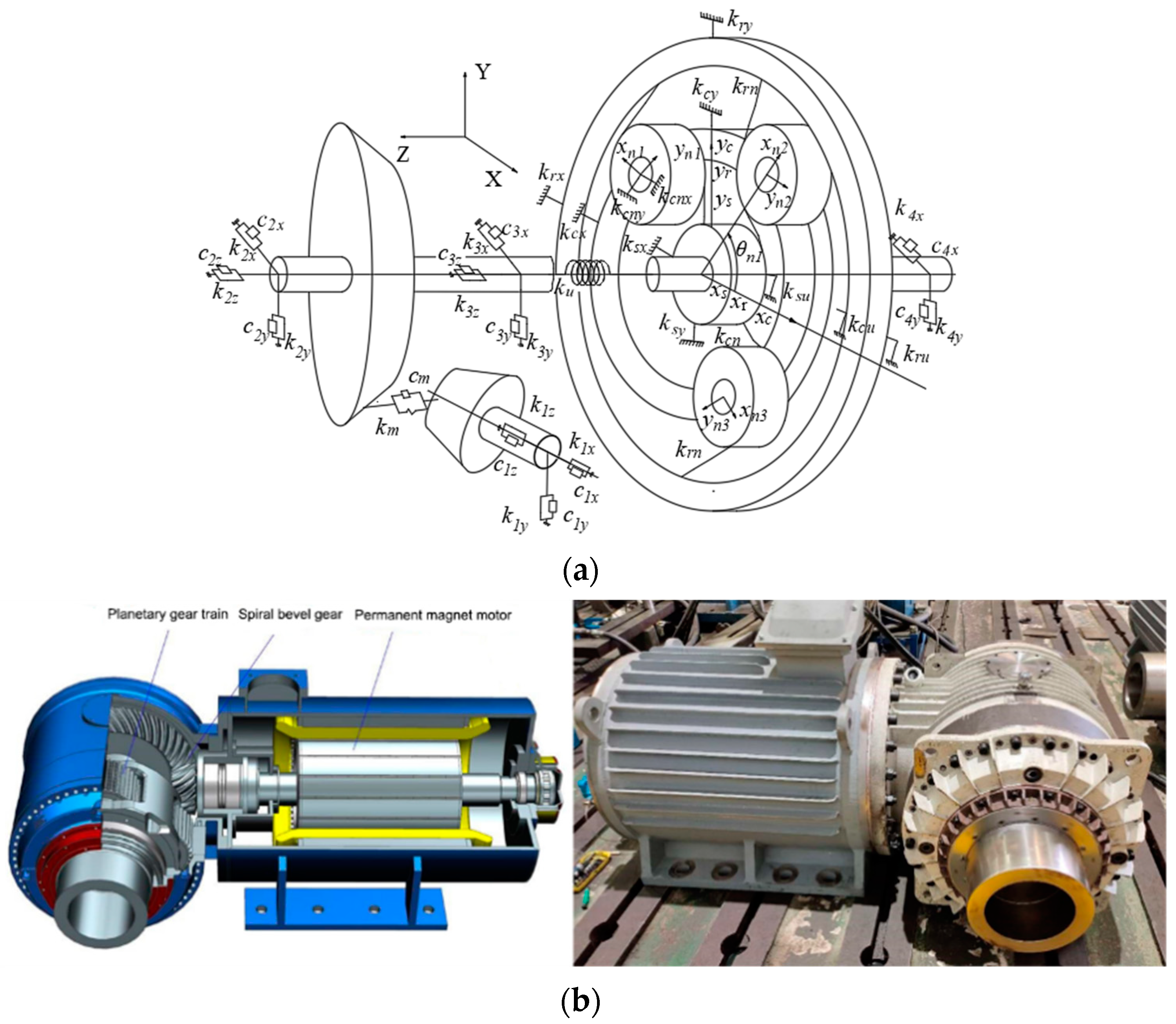
2. Dynamic Modeling
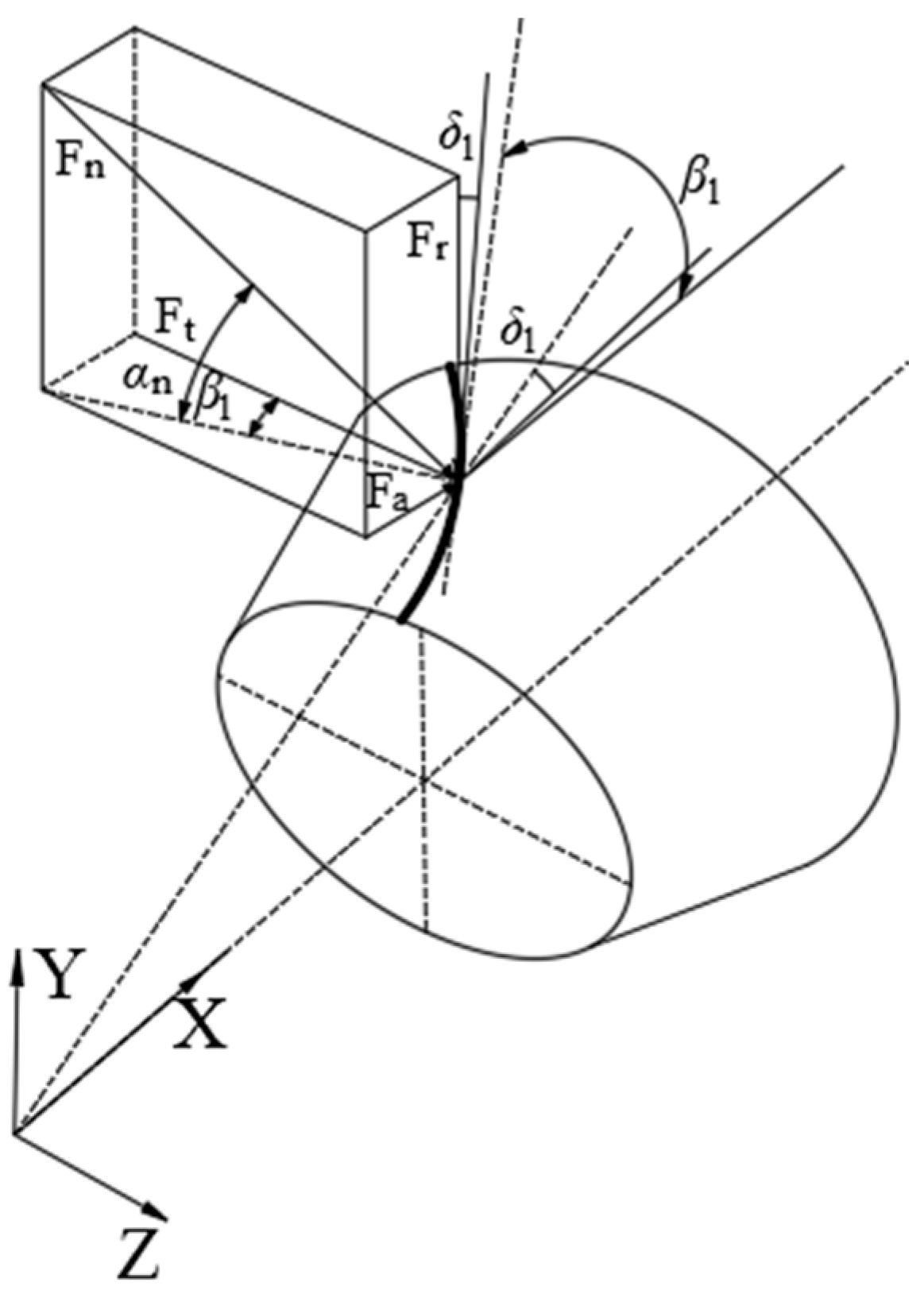
2.1. Dynamic Equation of a Spiral Bevel Gear
2.2. Dynamic Model of the Planetary Gear Transmission
3. Dynamic Analysis of the System
3.1. Parameters of the Model
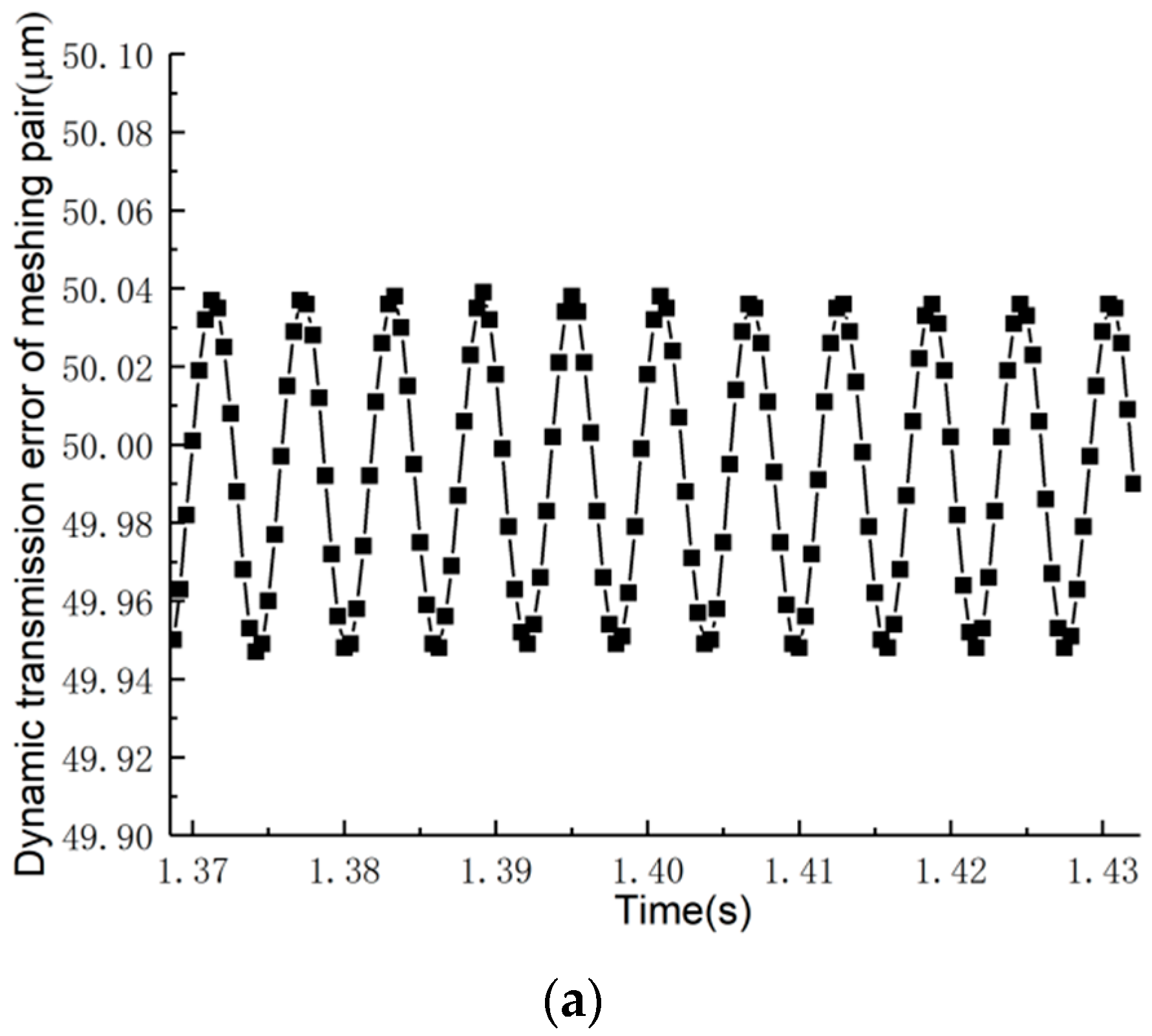
3.2. Dynamic Transmission Error
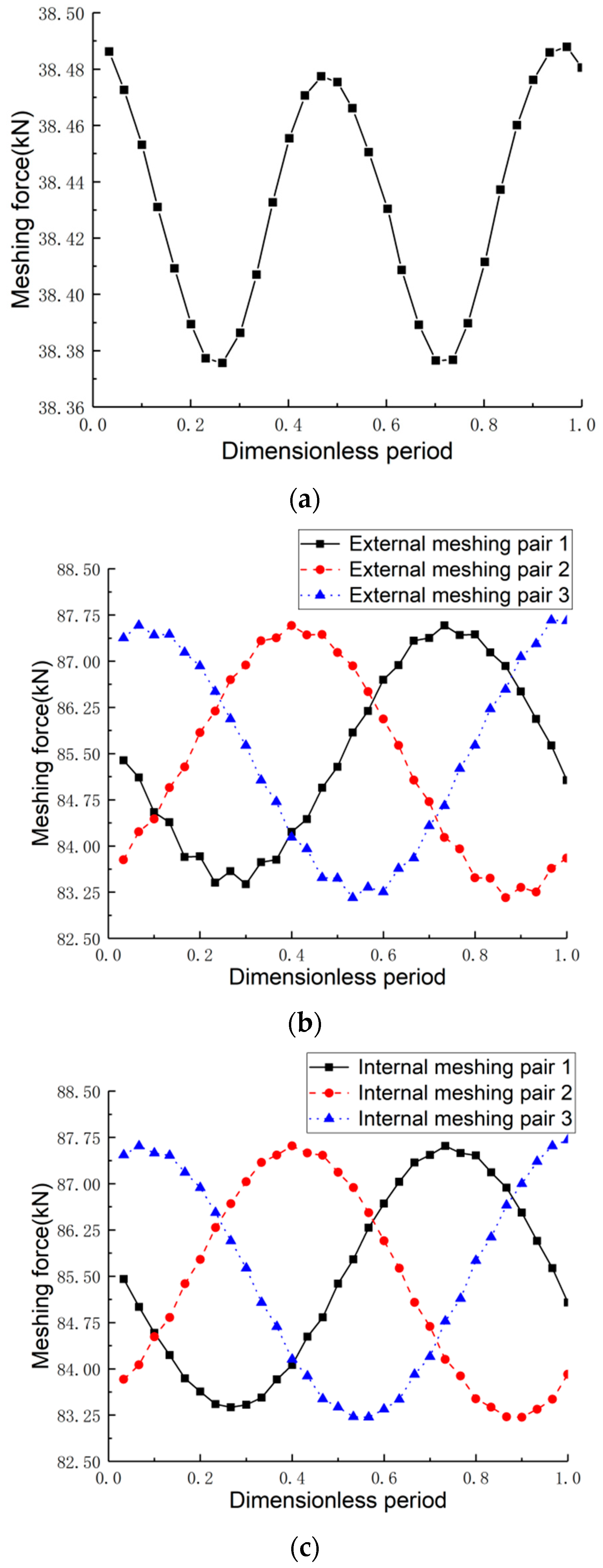
3.3. Dynamic Mesh Force
3.4. Influence of Rotational Speed on Dynamic Mesh Force
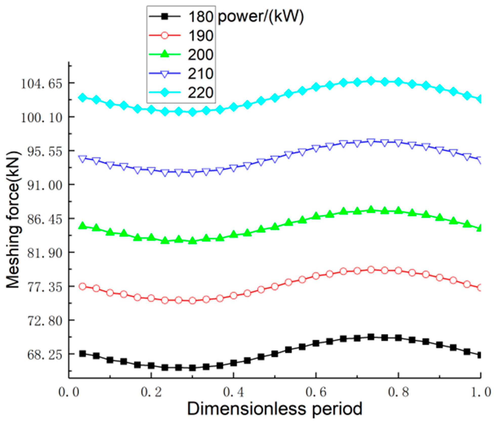
3.5. Influence of Different Loads on Dynamic Mesh Force
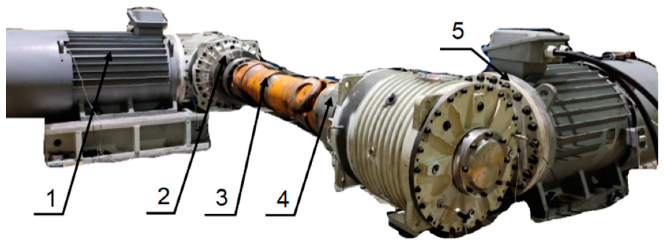
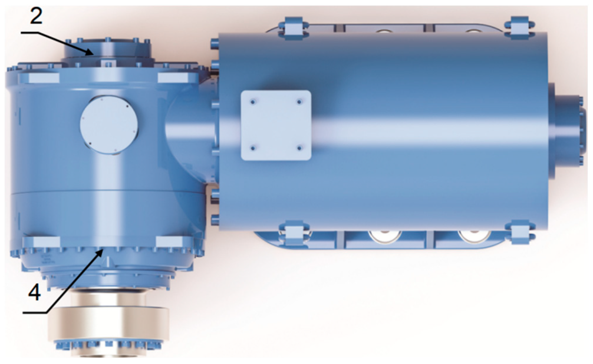
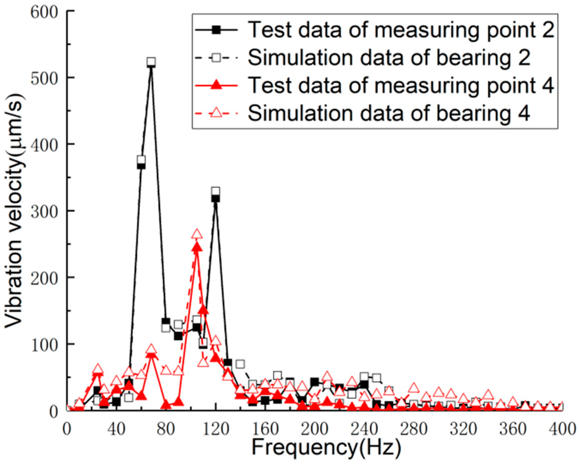
4. Discussion and Validation
5. Conclusions
Author Contributions
Funding
Institutional Review Board Statement
Informed Consent Statement
Data Availability Statement
Conflicts of Interest
Nomenclature
| C | overall damping matrix |
| cm | mesh damping |
| cij | damping coefficient of the gear in the direction of the coordinate axes (N·s/m) |
| em(t) | normal mesh error of gear pair |
| esn(t) | comprehensive mesh errors between the sun and planet |
| ern(t) | comprehensive mesh errors between the ring and planet |
| F | excitation vector (kN) |
| Ixp | rotational inertia of gears around the X axis (kg·m2) |
| Izg | rotational inertia of gears around the Z axis (kg·m2) |
| Ii | moment of inertia of each part (kg·m2) |
| K | overall stiffness matrix |
| ku | torsional stiffness of the shaft segment (N·m/rad) |
| ki | support stiffnesses of the sun/ring and planet carrier (N/m) |
| kij | stiffness coefficient of the gear in the direction of the coordinate axis |
| kix | support stiffness of each bearing in the X directions (N/m) |
| kiy | support stiffness of each bearing in the Y directions (N/m) |
| kiu | torsional stiffness of each part (N·m/rad) |
| kin | mesh stiffness between each gear pair |
| kcn | support stiffness between the planet gear and carrier (N/m) |
| km(t) | time-varying mesh stiffness |
| kij(t) | mesh stiffness of the ith gear pair |
| M | overall mass matrix of the system (kg) |
| mp | mass of the small bevel gear (kg) |
| mg | mass of the large bevel gear (kg) |
| mi | mass of the sun/planet gear, ring, and planet carrier (kg) |
| q | generalized displacement vector of the transmission system |
| rp | equivalent base radius at the small bevel gear reference points (m) |
| rg | equivalent base radius at the driven bevel gear reference points (m) |
| ri | base radius of each gear (m) |
| rc | radial distance from the axis center of the planet to the geometric center of the planet carrier (m) |
| T1 | input torque (N·m) |
| T2 | output torque (N·m) |
| Tp | input torque of the planetary transmission system (N·m) |
| Tg | output torque of the planetary transmission system (N·m) |
| ui | torsional line displacement |
| V | displacement transform vector |
| xi | translational deformation in the X direction |
| yi | translational deformation in the Y direction |
| α | pressure angle (°) |
| αn | normal pressure angle (°) |
| β1 | helix angle at the midpoint of the small bevel gear (°) |
| δ1 | pitch cone angle of the small bevel gear (°) |
| δsni | relative deformation along the line of action for the mesh pair between the sun and the planet |
| δrni | projected relative deformation of the ring and planetary gear mesh pair along the line of action |
| δcnxi | projected relative deformations between the planetary gear and carrier along the xni axis |
| δcnyi | projected relative deformations between the planetary gear and carrier along the yni axis |
| θxp | torsion angles of gears around the X axis |
| θzg | torsion angles of gears around the Z axis |
| θi | torsional elastic deformation of each part in planetary gear train |
| θsni | angles between the line of action of the sun and planetary and X axis, |
| θrni | angles between the line of action of the planetary wheel and the internal ring gear and X axis |
| θni | installation angle of the ith planetary gear |
| η | transmission efficiency |
References
- Tang, D.G.; Chen, G.M. Current situation and prospect of gear transmission technology. J. Mech. Eng. 1993, 29, 35–42. [Google Scholar]
- Xu, J.L.; Zeng, F.C.; Su, X.G. Coupled bending-torsional nonlinear vibration and bifurcation characteristics of spiral bevel gear system. Shock Vib. 2017, 2017, 6835301. [Google Scholar] [CrossRef] [Green Version]
- Cheng, Y.P.; Lim, T.C. Dynamics of hypoid gear transmission with nonlinear time-varying mesh characteristics. J. Mech. Des. 2003, 125, 373–382. [Google Scholar] [CrossRef]
- Tang, J.-Y.; Hu, Z.-H.; Wu, L.-J.; Chen, S.-Y. Effect of static transmission error on dynamic responses of spiral bevel gears. J. Cent. South Univ. 2013, 20, 640–647. [Google Scholar] [CrossRef]
- Wang, L.; Huang, Y.; Li, R.; Lin, T. Study on nonlinear vibration characteristics of spiral bevel transmission system. China Mech. Eng. 2007, 18, 260–264. [Google Scholar]
- Wang, L.; Li, R.; Lin, T.; Huang, Y. Analysis for coupling vibration of a spiral bevel gear system. China Mech. Eng. 2006, 17, 1431–1434. [Google Scholar]
- Zeng, Z.; Ding, K.; He, G.; Li, W. Space-time model and spectrum mechanism on vibration signal for planetary gear drive. Mech. Syst. Signal Process. 2019, 129, 164–185. [Google Scholar] [CrossRef]
- Gou, X.-F.; Li, G.-Y.; Zhu, L.-Y. Dynamic characteristics of a straight bevel gear drive system considering multi-state meshing and time-varying parameters. Mech. Mach. Theory 2022, 171, 104779. [Google Scholar] [CrossRef]
- Dong, H.; Liu, Z.-Y.; Zhao, X.; Hu, Y.-H.; Liu, Y.Z.; Zhao, L.X.; Hu, H.Y. Analysis of dynamic characteristics of power split spiral bevel gear transmission system based on teeth geometric contact analysis. Trans. Can. Soc. Mech. Eng. 2019, 43, 47–62. [Google Scholar] [CrossRef]
- Xiang, L.; Deng, Z.Q.; Hu, A.J. Dynamical analysis of planetary gear transmission system under support stiffness effects. Int. J. Bifurc. Chaos 2020, 30, 2050080. [Google Scholar] [CrossRef]
- Yavuz, S.D.; Saribay, Z.B.; Cigeroglu, E. Nonlinear time-varying dynamic analysis of a spiral bevel geared system. Nonlinear Dyn. 2018, 92, 1901–1919. [Google Scholar] [CrossRef]
- Yavuz, S.D.; Saribay, Z.B.; Cigeroglu, E. Nonlinear dynamic analysis of a drivetrain composed of spur, helical and spiral bevel gears. Nonlinear Dyn. 2020, 100, 3145–3170. [Google Scholar] [CrossRef]
- Lafi, W.; Djemal, F.; Tounsi, D.; Akrout, A.; Walha, L.; Haddar, M. Dynamic modelling of differential bevel gear system in the presence of a defect. Mech. Mach. Theory 2019, 139, 81–108. [Google Scholar] [CrossRef]
- Lafi, W.; Djemal, F.; Tounsi, D.; Akrout, A.; Walha, L.; Haddar, M. Non-probabilistic interval process method for analyzing two-stage straight bevel gear system with uncertain time-varying parameters. Proc. Inst. Mech. Eng. Part C J. Mech. Eng. Sci. 2021, 235, 3162–3178. [Google Scholar] [CrossRef]
- Cao, W.; Pu, W.; Wang, J.X. Tribo-dynamic model and fatigue life analysis of spiral bevel gears. Eur. J. Mech. A Solids 2018, 74, 124–138. [Google Scholar] [CrossRef]
- He, Z.X.; Chang, L.H.; Liu, L. Dynamic response analysis of planetary gear transmission system coupled with gearbox vibrations. J. South China Univ. Technol. (Nat. Sci. Ed.) 2015, 43, 128–134+148. [Google Scholar]
- Gu, X.; Velex, P. A dynamic model to study the influence of planet position errors in planetary gears. J. Sound Vib. 2012, 331, 4554–4574. [Google Scholar] [CrossRef]
- Velex, P.; Chapron, M.; Fakhfakh, H.; Bruyère, J.; Becquerelle, S. On transmission errors and profile modifications minimising dynamic tooth loads in multi-mesh gears. J. Sound Vib. 2016, 379, 28–52. [Google Scholar] [CrossRef]
- Yang, H.; Li, X.; Xu, J.; Yang, Z.; Chen, R. Dynamic characteristics analysis of planetary gear system with internal and external excitation under turbulent wind load. Sci. Prog. 2021, 104, 368504211035604. [Google Scholar] [CrossRef]
- Jian, G.-X.; Wang, Y.-Q.; Zhang, P.; Li, Y.-K.; Luo, H. Analysis of lubrication performance for internal meshing gear pair considering vibration. J. Cent. South Univ. 2021, 28, 126–139. [Google Scholar] [CrossRef]
- Wang, C.X.; Dong, B.; Parker, R.G. Impact of planet mesh phasing on the vibration of three-dimensional planetary/epicyclic gears. Mech. Mach. Theory 2021, 164, 104422. [Google Scholar] [CrossRef]
- Wang, S.Y.; Zhu, R.P. Nonlinear torsional dynamics of star gearing transmission system of GTF gearbox. Shock Vib. 2020, 2020, 6206418. [Google Scholar] [CrossRef]
- Tang, X.; Bao, H.Y.; Lu, F.X. Nonlinear dynamic analysis of planetary gear train system with meshing beyond pitch point. Trans. Nanjing Univ. Aeronaut. Astronaut. 2020, 37, 884–897. [Google Scholar]
- Kahnamouei, J.T.; Yang, J.M. Development and verification of a computationally efficient stochastically linearized planetary gear train model with ring elasticity. Mech. Mach. Theory 2021, 155, 104061. [Google Scholar] [CrossRef]
- Wang, C.X.; Parker, R.G. Nonlinear dynamics of lumped-parameter planetary gears with general mesh phasing. J. Sound Vib. 2022, 523, 116682. [Google Scholar] [CrossRef]
- Yang, H.; Shi, W.; Guo, L.; Zhao, Y.; Yuan, R. Study on mesh stiffness and sensitivity analysis of planetary gear system considering the deformation effect of carrier and bearing. Eng. Fail. Anal. 2022, 135, 106146. [Google Scholar] [CrossRef]
- Xiang, L.; Gao, N.; Hu, A.J. Dynamic analysis of a planetary gear system with multiple nonlinear parameters. J. Comput. Appl. Math. 2018, 327, 325–340. [Google Scholar] [CrossRef]
- Wang, X. Nonlinear dynamic characteristics of fixed-axis gear wear in multistage gear transmission systems. Shock Vib. 2019, 2019, 5641617. [Google Scholar] [CrossRef] [Green Version]
- Karray, M.; Feki, N.; Khabou, M.T.; Chaari, F.; Haddar, M. Modal analysis of gearbox transmission system in bucket wheel excavator. J. Theor. Appl. Mech. 2017, 55, 253–264. [Google Scholar] [CrossRef] [Green Version]
- Wang, L.; Li, R.; Lin, T.; Yang, C. Analysis for coupled vibration of helical gear transmission system. Mach. Des. Res. 2002, 18, 30–31. [Google Scholar]
- Nanjing Gaojing Gear Group Co. Ltd. MGDS-E Series Bucket Lift Permanent Magnet-Gear Drive System; Nanjing Gaojing Gear Group Co. Ltd.: Nanjing, China, 2020. [Google Scholar]
- Chang, L.H.; He, Z.; Liu, L.; Liu, Q. Express method for determining the transmission error and mesh stiffness of helical gears. J. Vib. Shock. 2017, 36, 157–162+174. [Google Scholar]
- Chang, L.H. A Generalized Dynamic Model for Parallel Shaft Gear Transmissions and the Influences of Dynamic Excitations; Northwestern Polytechnical University: Xi’an, China, 2014. [Google Scholar]
- Liu, G. Low Noise Design Theory and Method of Gear Transmission; Science Press: Beijing, China, 2021. [Google Scholar]
- Pu, L.G.; Chen, G.D.; Wu, L.Y. Mechanical Design, 9th ed.; Higher Education Press: Beijing, China, 2013. [Google Scholar]


| Parameter | Small Bevel Gear | Large Bevel Gear | Sun | Planet | Inner Ring Gear | Planet Carrier |
|---|---|---|---|---|---|---|
| Modulus | 10.85 | 10.85 | 4.5 | 4.5 | 4.5 | - |
| Number of teeth | 16 | 57 | 23 | 35 | 93 | - |
| Equivalent diameter (m) | 0.18 | 0.56 | 0.1 | 0.16 | 0.42 | 0.34 |
| Pressure angle (°) | 20 | 20 | 20 | 20 | 20 | - |
| Helix angle (°) | 30 | 30 | 0 | 0 | 0 | - |
| Mass (kg) | 2.14 | 118.73 | 7.38 | 5.20 | 36.71 | 242.75 |
| Moment of inertia (kg·m2) | 0.16 | 5.41 | 0.01 | 0.29 | 1.83 | 7.03 |
| Support stiffness (N/m) | 2 × 10⁸ | 2 × 10⁸ | 1.18 × 10⁹ | 5 × 10⁷ | 7.38 × 10⁹ | 8.63 × 10⁸ |
| Torsional stiffness (N/m) | 2.9 × 10⁸ | 2.9 × 10⁸ | 3.47 × 10⁹ | - | 83.4 × 10⁹ | 3.64 × 10⁸ |
| Test Equipment | Type | Test Equipment | Type |
|---|---|---|---|
| Tractor motor | TYCPT 400S-20 | Coupling | SWC285 |
| Adapter plate | MH3S170H22.4AT | Torque meter | JN338-20000 |
| Vibration measurement system | B&K vibration measuring system (including one-way vibration measuring probe) | Sensor | B&K speed sensor |
| Measurement Point | Test Peak (μm/s) | Simulation Peak (μm/s) | Error (%) |
|---|---|---|---|
| Point 1 | 514.26 | 533.80 | 3.80 |
| Point 2 | 260.55 | 283.58 | 8.84 |
Disclaimer/Publisher’s Note: The statements, opinions and data contained in all publications are solely those of the individual author(s) and contributor(s) and not of MDPI and/or the editor(s). MDPI and/or the editor(s) disclaim responsibility for any injury to people or property resulting from any ideas, methods, instructions or products referred to in the content. |
© 2023 by the authors. Licensee MDPI, Basel, Switzerland. This article is an open access article distributed under the terms and conditions of the Creative Commons Attribution (CC BY) license (https://creativecommons.org/licenses/by/4.0/).
Share and Cite
He, Z.; Xing, Z.; Zhou, Q.; Chang, L. Dynamic Analysis of a Combined Spiral Bevel Gear and Planetary Gear Set in a Bucket Elevator with High Power Density. Sustainability 2023, 15, 4304. https://doi.org/10.3390/su15054304
He Z, Xing Z, Zhou Q, Chang L. Dynamic Analysis of a Combined Spiral Bevel Gear and Planetary Gear Set in a Bucket Elevator with High Power Density. Sustainability. 2023; 15(5):4304. https://doi.org/10.3390/su15054304
Chicago/Turabian StyleHe, Zhaoxia, Zengfei Xing, Qing Zhou, and Lehao Chang. 2023. "Dynamic Analysis of a Combined Spiral Bevel Gear and Planetary Gear Set in a Bucket Elevator with High Power Density" Sustainability 15, no. 5: 4304. https://doi.org/10.3390/su15054304