Abstract
The stability of damaged rock mass is a critical problem in the control of surrounding rock in underground engineering. As the main macroscopic defect of rock surrounding engineering, it is of great significance to study its propagation mechanism and the experimental characteristics of rock mechanics. Surface-fractured rock mass is a typical representative of three-dimensional fracture. To reveal the failure mechanism of surface-fractured rock mass, a three-dimensional mechanical failure model of a surface-fractured rock specimen was established, including the initiation, crack propagation, and cooperative deformation of the rock micro-element. Taking the depth of the surface horizontal fissure as a variable, standard rock specimens with surface horizontal fissures of different depths were prepared, and an experimental study of surface-fractured rock specimens was carried out. The RMT rock mechanics test system was used to perform uniaxial compression tests on standard specimens containing fractured rock specimens of different depths. The complete stress–strain curves of samples with different fracture depths were obtained, and the influence of different fracture depths on rock strength and deformation characteristics was analyzed. The crack initiation, propagation, and failure modes of the specimens under uniaxial compression were analyzed based on high-speed camera technology. Through the combination of 3D image processing and acoustic emission monitoring, differences between failure before and after the peak in both asymmetrically damaged rock specimens and symmetrically damaged rock specimens were found. The mechanism of weak strength and weak stability of asymmetrically damaged rock specimens after the peak was explained theoretically. The research results showed that the existence of the horizontal joint plane directly led to a significant reduction in the strength of the jointed rock sample, and the fracture depth played an important role in controlling the failure mode of the jointed rock specimens. The uniaxial compression of rock specimens with horizontal non-penetrating surface fissures produced three-dimensional failure modes, and the depth of surface fissures changed the failure mode of the specimens under uniaxial compression. As the crack depth increased, the failure mode of the specimen changed from tensile failure to shear failure. The surface crack sample showed regional asymmetric failure and poor structural stability.
1. Introduction
Rock engineering is an important component in the construction of the infrastructure. The existence of fractured rock mass poses a great challenge for rock engineering [1,2]. Innovations in geological exploration technology have greatly improved the precision of rock damage detection [3,4,5]. In rock engineering, changes in internal defects are an important factor in rock mass failure and instability [6,7,8]. In particular, there are substantial hidden dangers and threats of geotechnical problems in rock mass. The deformation and failure of damaged rock greatly increases technical difficulty and construction cost [9,10,11]. The existing basic research shows that the type, number, spatial position relationship, and lithology of cracks are the internal factors that determine rock strength, while the stress state is the external condition that controls rock mass failure. According to the occurrence state of a crack in rock engineering, it can be categorized as a surface crack, a deep buried crack, or a through crack. The three-dimensional failure of fractured rock mass is still a pressing and difficult problem in current research.
Due to the limitations caused by research complexity and technical conditions, it is common for scholars to simplify and deconstruct complex problems. With respect to penetrating fissures, researchers usually conduct two-dimensional processing of the complex three-dimensional state. Yang et al. [12,13] systematically studied the dip angle, width, length, and spatial distribution of fractured rock specimens with the help of an indoor servo testing machine. At the same time, the influence mechanism of each factor on rock failure and the damage degree of various cracks in rock specimens can be obtained using control variables and a simplified decomposition method. Zhao et al. [14,15] studied the crack propagation law of three kinds of rocks through the triaxial test, analyzed the crack propagation law of rocks, and obtained the modified shear strength model for rock specimens. Liu et al. [16] obtained the action mechanism of different crack angles in rock compression failure by means of acoustic emission and numerical image processing technology.
Yu et al. [17,18,19] proposed a mechanical model for the deformation and failure of heterogeneous composite rock specimens by studying the propagation mechanism of heterogeneous rock fracture and the variation rule of AE in the failure process. Zhao et al. [20,21] studied the failure law of single-fractured rock specimens under water-force coupling through triaxial compression and acoustic emission tests, and proposed the compression-shear fracture model under water-force coupling conditions. Chen et al. [22] studied the dominant propagation law of cracks through tests on prefabricated parallel double-fissure rock. All of the above studies were carried out on samples with single straight cracks. In addition, some scholars have carried out studies on other forms of cracks. Fu et al. [23,24] conducted compression failure tests on built-in oval precast cracks with different angles, and they concluded that the number of cracks generated in three-dimensional specimens of unsaturated resin cracks was much higher than that in two-dimensional specimens in the process of compression failure. Li et al. [25] found that the expansion of prefabricated cracks was the direct cause of specimen failure, and they conducted a compression failure test on a ceramic specimen with built-in circular cracks. At present, due to the limitations of specimen production technology and observation technology, laboratory test specimens of deeply buried cracks are obtained through 3D printing technology and other means. Ju et al. [26,27] realized stress field monitoring of the whole process of compression failure for a cube specimen with cracks using 3D printing technology. Zhou et al. [28,29] reconstructed the spatial structure of proto-rock in resin specimens through 3D printing technology. At the same time, the crack propagation law and failure mechanism of crack specimens in uniaxial and biaxial failure processes were obtained.
The above research results laid a foundation for revealing the fracture mechanism of surface cracks. However, the structure of the surface-fractured rock mass and the boundary conditions of shallowly buried fractures leads to complexity of the failure modes in the surrounding rock. The structure of the surface-fractured rock mass leads to a complication of the failure mode in rock surrounding engineering. Therefore, the influence mode of the depth of surface cracks on the failure mechanism in rock surrounding engineering still needs further study. Based on this, horizontal-fractured rock specimens with different fracture depths were obtained by prefabricating horizontal fractures of different depths in the middle of white sandstone standard specimens. An RMT rock mechanics experimental system, an acoustic emission detector, and a high-speed camera were used to set up the test platform. The uniaxial compression failure tests were carried out on fractured rock specimens with different depths. The stress–strain data, acoustic emission data, and crack propagation patterns at different times during the whole process of specimen failure were obtained. The failure mechanism of horizontal surface-fractured rock specimens at different depths was revealed and the impact of crack depth on the failure of surface-fractured rock specimens was obtained.
2. Theoretical Model
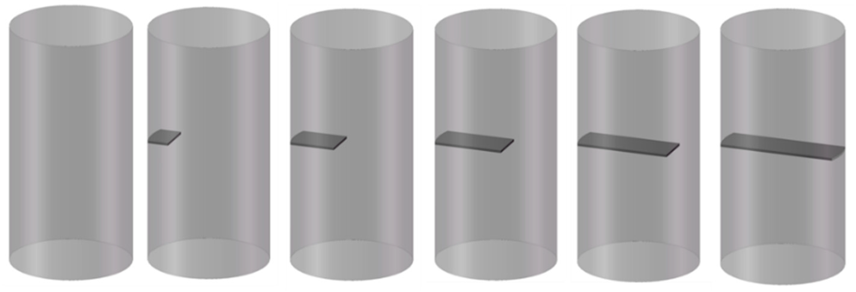
The structure of rock specimens with surface cracks is three-dimensionally asymmetrical. The application of a two-dimensional crack propagation mechanism to surface-cracked rock samples has limitations. In order to obtain the failure mechanism for rock samples with surface cracks, the following standard rock specimens were selected for the test. A three-dimensional model of the test piece is shown in Figure 1.
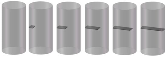
Figure 1.
Three-dimensional model of standard rock specimens.
The damage model of surface-fractured rock specimens was divided into the damaged part and the undamaged part. The failure process in a rock specimen was divided into crack initiation, crack propagation, and synergistic deformation.
(1) Crack initiation
In order to better solve the three-dimensional propagation problem of a surface damage crack, Palaniswammy and Knauss studied the point failure mechanism of the crack front through force analysis of the crack tip, and the tensile stress criterion for a three-dimensional crack initiation was obtained with the maximum tensile stress as the standard. Li et al. [30] extended the point failure of the tensile stress criterion to the surface failure of cracks. The composition of the first principal differential planes (COFPDP) was proposed. The three-dimensional crack initiation criterion at each point of the crack tip was proposed in the COFPDP method.
(2) Crack propagation
The three-dimensional propagation of surface cracks follows two important characteristics of compressive closed crack propagation: the asymptote of crack propagation tends to the direction of maximum principal stress, and the tensile expansion of cracks will cause local volume expansion in the rock specimen.
(3) Collaborative deformation
The surface-fractured rock specimen is composed of the damaged part and the undamaged part. In the first stage, the rock specimen produces elastic deformation, the original cracks of the damaged rock specimen are gradually closed, and the undamaged rock specimen is compacted with micropores. In the second stage, the crack of the damaged rock specimen starts to crack and expand, and the undamaged rock specimen starts to microcrack. In the third stage, the undamaged rock specimen reaches the elastic deformation limit, and the microcracks in the undamaged rock specimen and the cracks in the damaged rock specimen begin to expand at the same time.
Three-dimensional fractures have multiplicity, and multiple fracture results can occur on different scales within a fault. The superposition of multiple fractures leads to a diversification of rock fragmentation. Through a comparison of the three-dimensional models of the test specimen, it was found that there are three crack fronts, A, B, and C, in a surface crack, which is different from the case of a through crack. The model is shown in Figure 2.
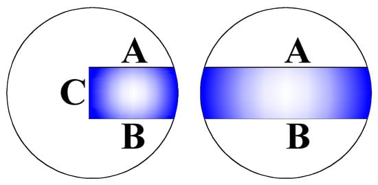
Figure 2.
Distribution of surface fissure and penetrating fissure fronts.
3. Test Scheme
3.1. Specimen Preparation
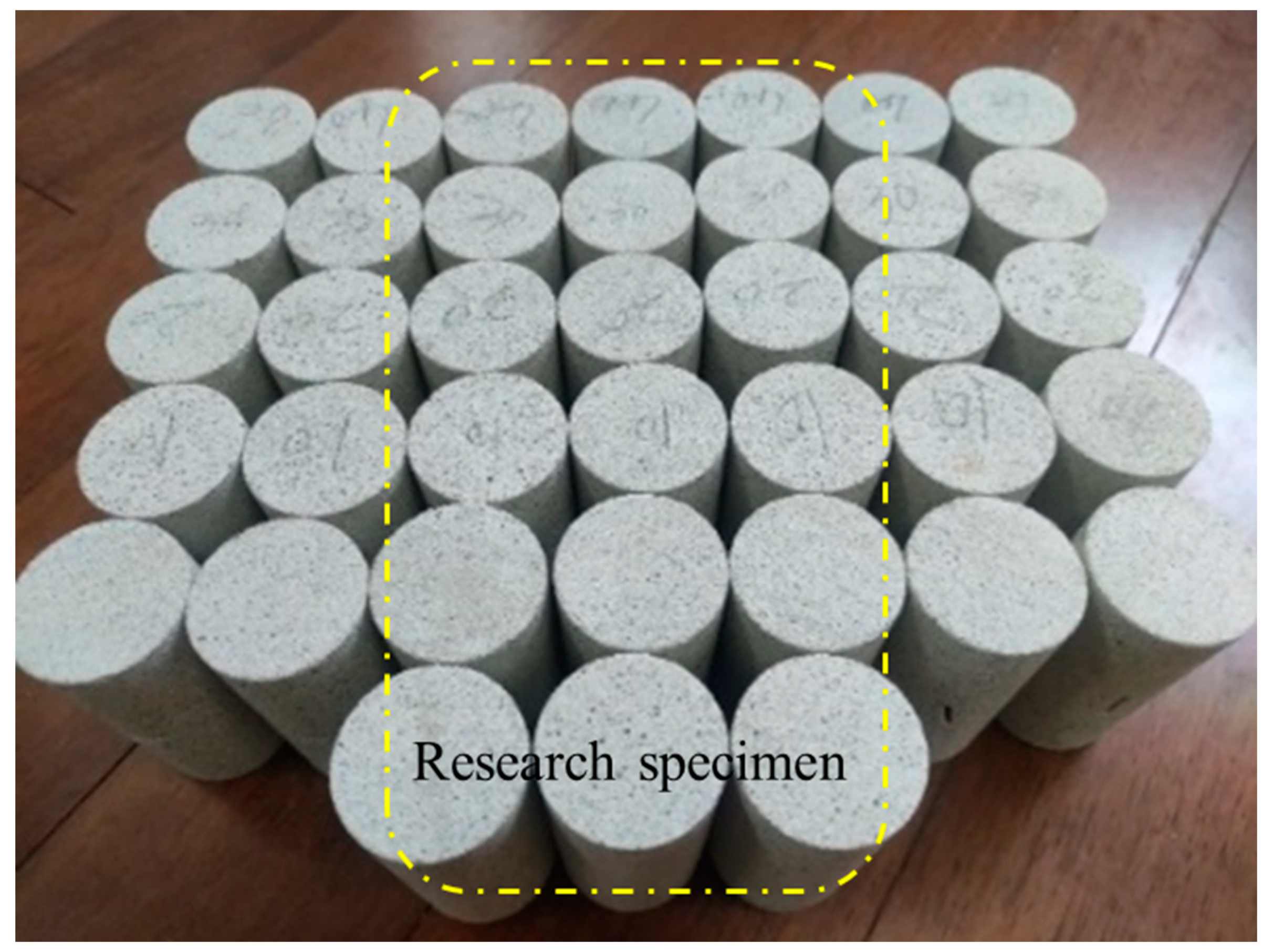
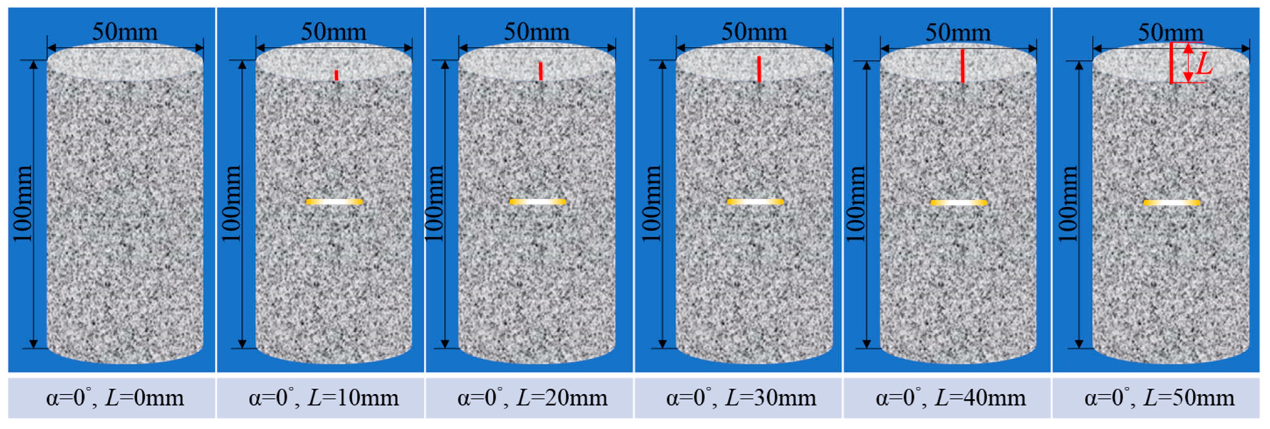
The white sandstone rock sample was taken from a mining area in southwestern China. It was medium strength rock. The design processing size of the test pieces was φ 50 mm × 100 mm standard size as specified by the American Society for Testing and Materials (ASTM) [31]. The surface crack on each specimen had an angle between crack and horizontal direction α = 0°, and it was 1.5 mm in width and 15 mm in length. The specimens had 0 mm, 10 mm, 20 mm, 30 mm, 40 mm, or 50 mm in damage depth L, and the test pieces were set as 0–0, 0–10, 0–20, 0–30, 0-40, and 0–50, respectively. The specimens and relevant dimensions are shown in Figure 3 and Figure 4.

Figure 3.
Specimens of white sandstone with single nodge.
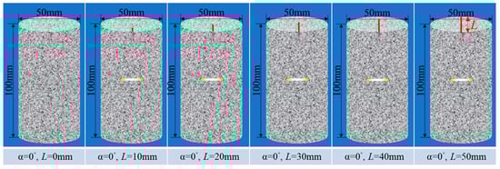
Figure 4.
Standard specimen size of white sandstone with single nodge.
3.2. Experimental Device and Method
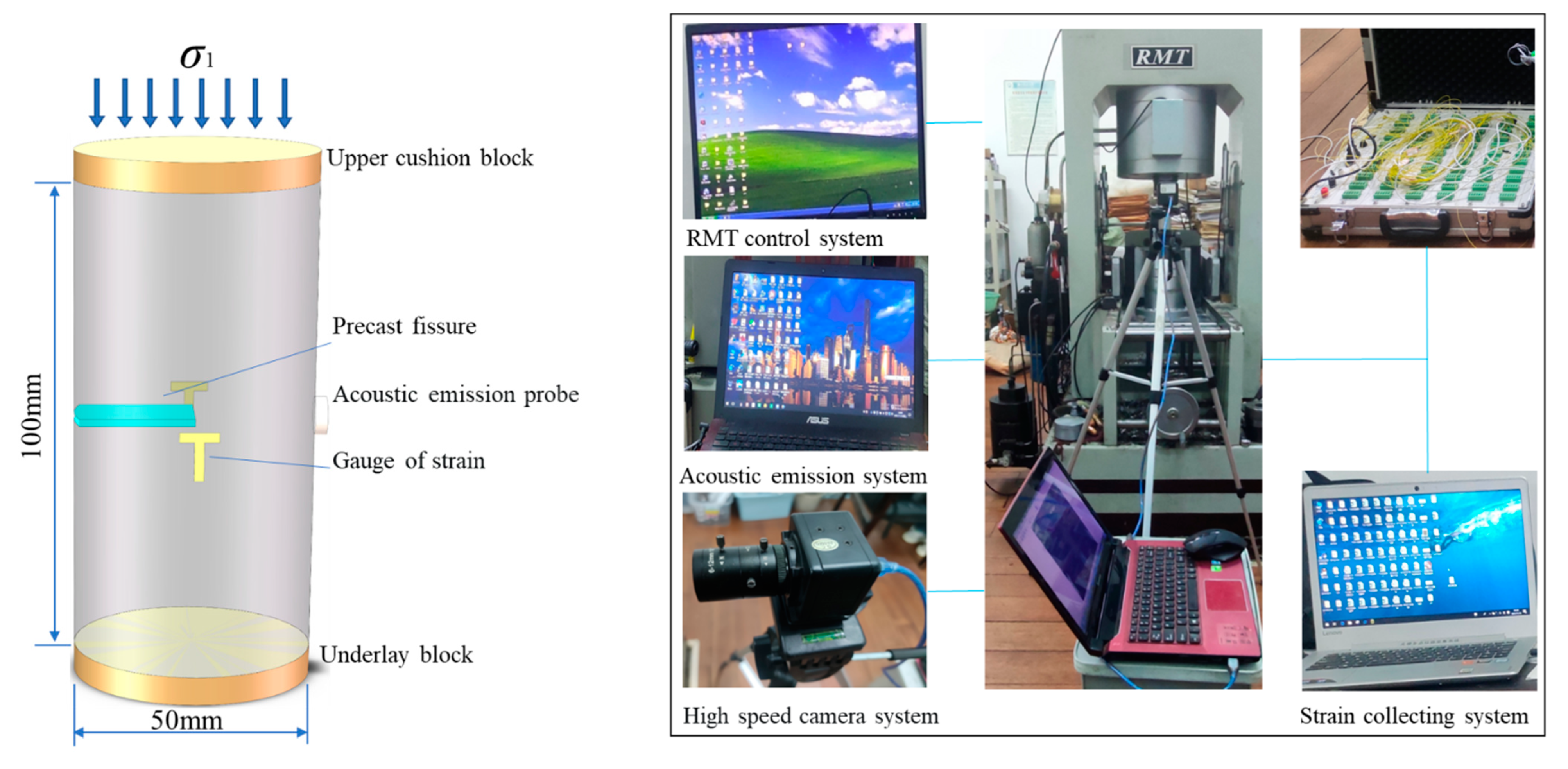
The test loading equipment was the RMT-150C electro-hydraulic servo rock mechanics test system developed by the Wuhan Institute of Geotechnical Mechanics, Chinese Academy of Sciences. The loading mode was linear loading, and the loading rate was 2 KN/S. The auxiliary equipment for the test included an acoustic emission system, a high-speed camera, and a strain gauge, which could conduct detection and data acquisition for the whole process of the rock specimen failure test. Two sets of “T” shaped 120-10AA resistance strain gauges were pasted at the relative position in the middle of the fractured rock specimens to detect the radial deformation and circumferential deformation of the specimen. The acoustic emission probe was arranged in the central area behind the surface crack of the test piece to detect the crack propagation law and the failure process of the test piece. A rock loading diagram is shown in Figure 5.
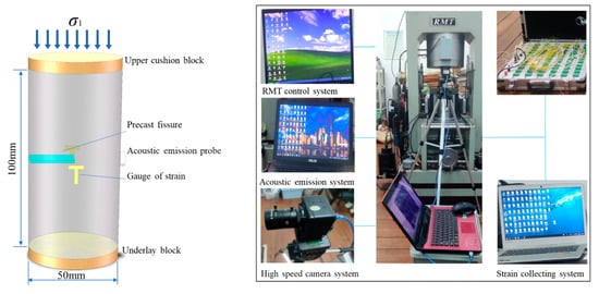
Figure 5.
RMT rock mechanics test system.
4. Mechanical Properties of White Sandstone Specimens
4.1. Peak Stress Characteristics of Rock Specimens
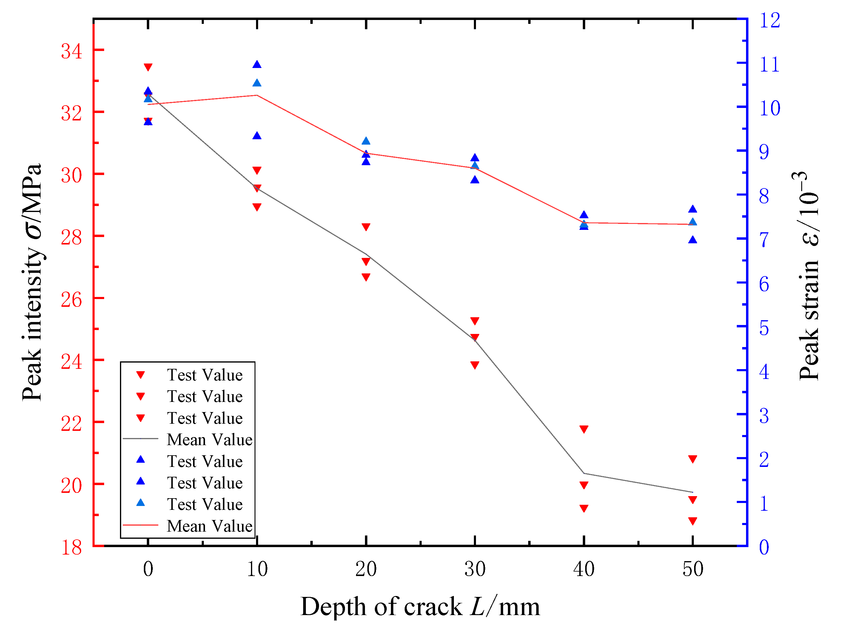
The peak strain and peak stress curves of the white sandstone specimens with different fracture depths are shown in Figure 6. The peak stress for the white sandstone specimens 0–0, 0–10, 0–20, 0–30, 0–40, and 0–50 were 32.58 MPa, 29.53 MPa, 27.41 MPa, 24.63 MPa, 20.34 MPa, and 19.73 MPa, respectively, and the peak strains were 10.05‰, 10.26‰, 8.67‰, 8.60‰, 8.30‰, and 7.32‰, respectively. The test results showed that the UCS (uniaxial compressive strength) of the crack specimen was negatively correlated with the crack depth, and the peak stress of the specimen decreased gradually with the increase in the crack depth. At the same time, the peak strain and peak stress of each specimen showed a synergistic change, and it could be concluded that the crack depth was related to the uniaxial compressive strength of the crack specimen. The peak stress of specimens 0–40 and 0–50 were 20.34 MPa and 19.73 MPa, respectively. It could be concluded that when the crack depth reached 4/5 of the specimen diameter, the damaged part of the rock specimen played a leading role in the failure of the specimen, and the surface crack and the through crack had basically the same strength loss for the specimen. The peak strain differences of test pieces 0–0 and 0–10, 0–20 and 0–30, and 0–40 and 0–50 were 0.21‰, 0.34‰, and 0.04‰, respectively, and the absolute peak strain differences of test pieces 0–10 and 0–20, and of 0–30 and 0–40, were 1.32‰ and 1.24‰, respectively. Through comparative analysis, it was concluded that the absolute differences of peak strain between 0–0 and 0–10, between 0–20 and 0–30, and between 0–40 and 0–50 of the test pieces were small, which indicated that the crack depth of these groups had little influence on the structural failure mode of the test pieces, and the axial deformation failure of each group had commonness in structure.
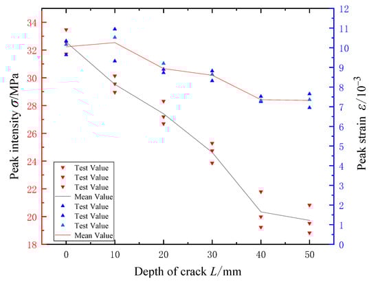
Figure 6.
The variation law of crack strength with crack depth L.
4.2. Damage Characteristics of Rock Specimens
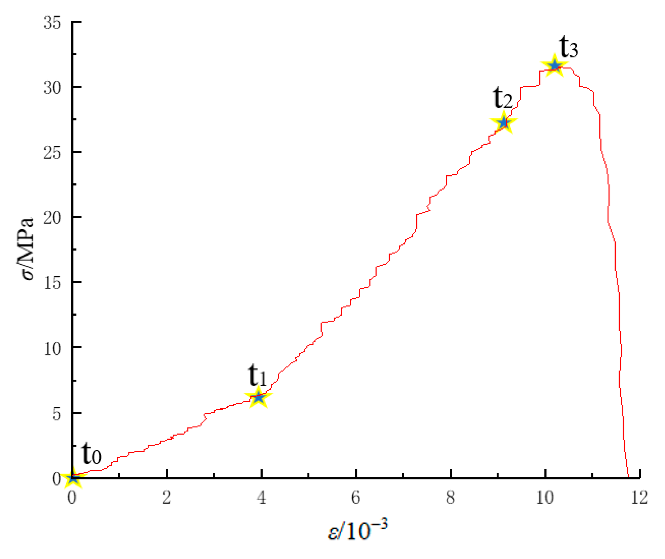
In the test, the complete stress–strain curves of the 0–0 and 0–50 specimens could be divided into the following stages: (1) t0–t1, the primary void and fissure compaction stage of rock specimens; (2) t1–t2, near-linear deformation stage of elastic deformation and microfracture of rock specimens; (3) t2–t3, the microcrack of rock specimens extends to the stable fracture stage of macro crack; (4) t2–t3, the microcrack of rock specimens extends to the unstable fracture stage of macro crack; (5) from time t3, the macro cracks of the rock specimens ran through the non-uniform deformation fracture stage. The complete specimen of white sandstone and the through-crack specimen were both macro-structurally symmetrical rock specimens, and the full stress–strain curves of both were spatially symmetrical with uniform deformation stages at the t0–t3 stage. Therefore, the complete rock specimen and the through-crack specimen could be analyzed through two-dimensional fracture mechanics. On the other hand, the structure of the rock specimens with surface cracks had macro asymmetry. The loading path is shown in Figure 7.
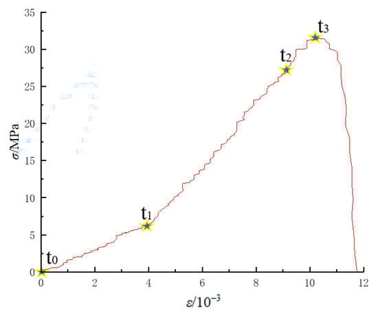
Figure 7.
Typical total stress–strain curves of rock deformation.
4.3. Analysis of Failure Evolution Process of Rock Specimens
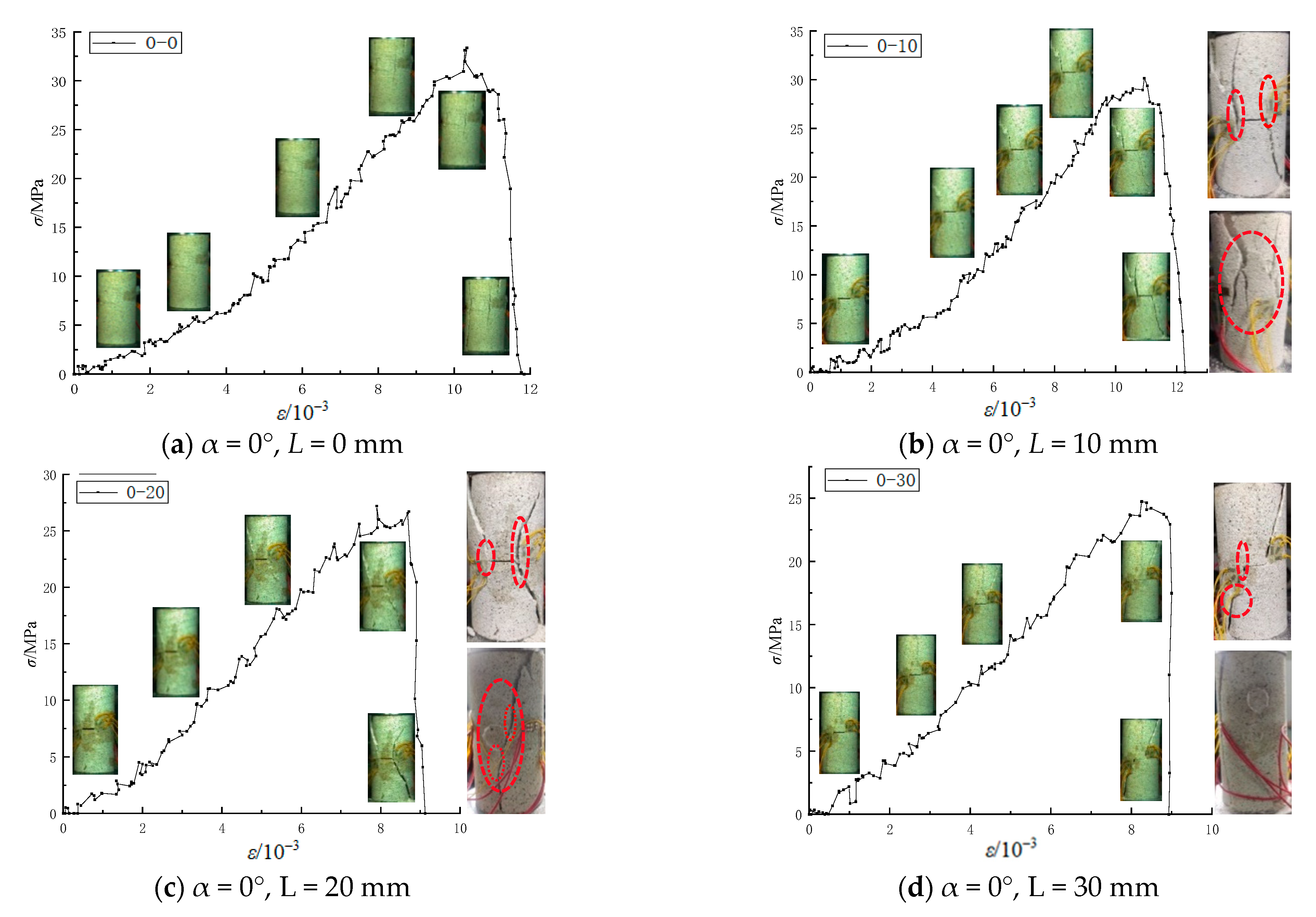
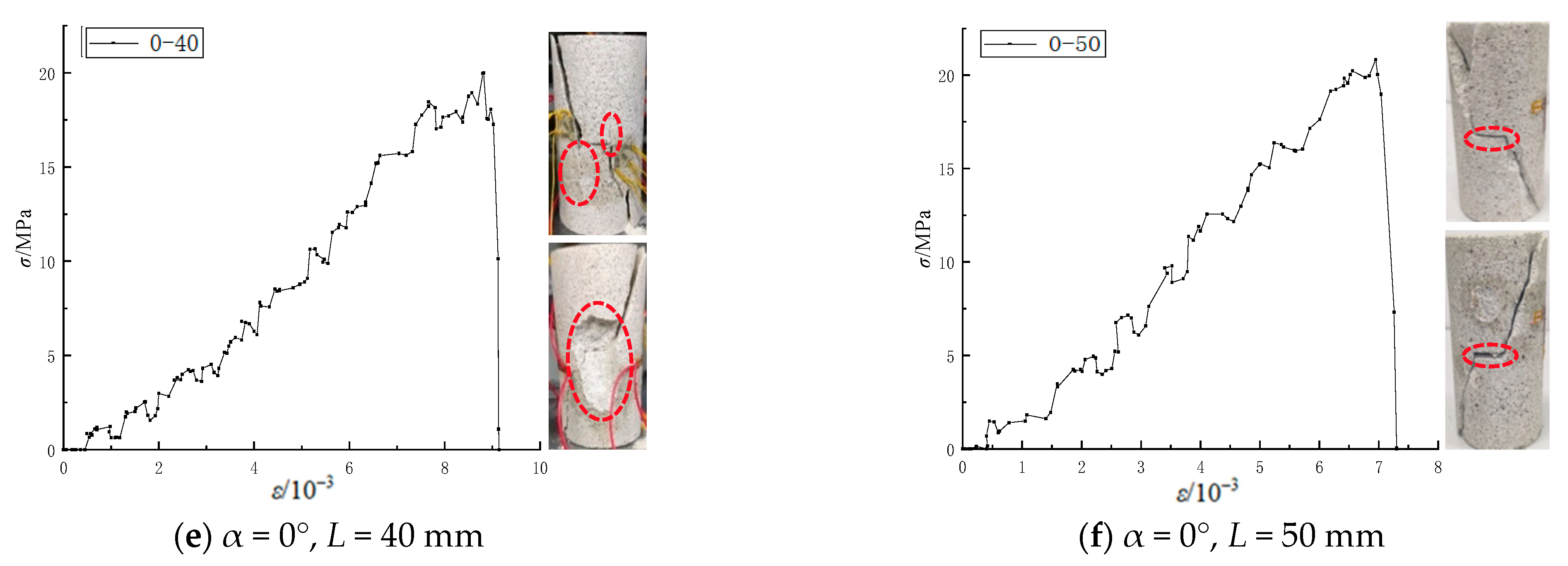
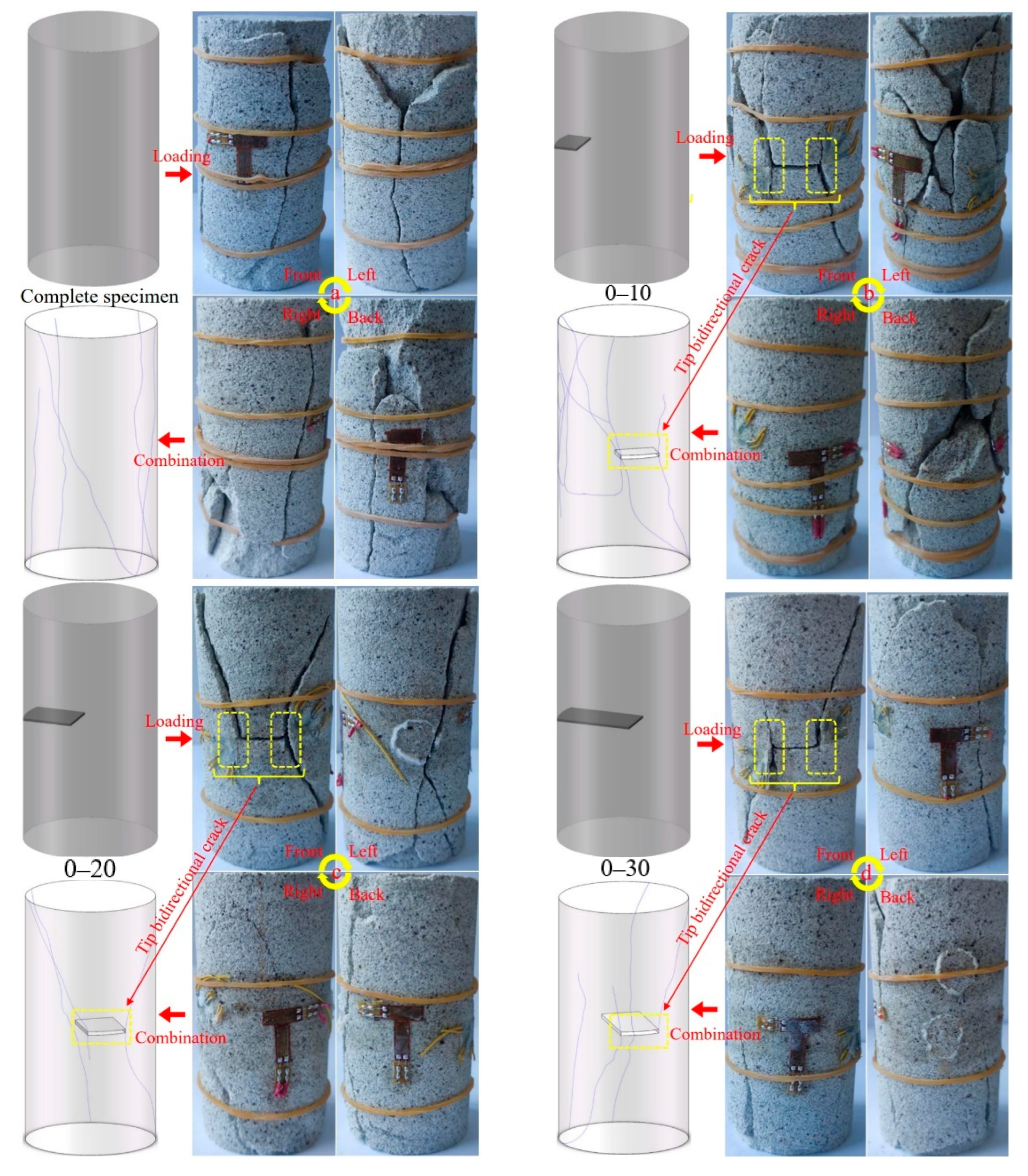
Based on analysis of the failure modes of the rock specimens, it was concluded that with the increases in the crack depth, the rock specimens gradually transitioned from the tensile failure of the complete specimen to the shear failure of the through-crack specimen. The specific failure modes of the rock specimens were as follows: (1) As shown in Figure 8a, the failure mode of a standard intact specimen was shear failure. Cracks were initiated at the end and middle of the specimen. The main types of failure cracks were two-dimensional plane through-cracks. (2) As shown in Figure 8b, the failure form of the 0–10 fracture specimens with a crack depth of 10 mm was tensile failure. Although there was little difference in the peak strength between specimen 0–10 and specimen 0–0, there were great differences in the failure forms of these specimens, and specimen 0–10 had a significant asymmetric failure. The crack initiation position not only appeared at both ends of the horizontal joint, but also existed in the part far away from the crack. There were two failure mechanisms in this specimen, one was the failure mode of the defective rock specimen caused by fracture tip initiation, and the other was the failure mode of the non-defective rock specimen far away from the fracture area. The early failure form of the fractured rock specimen was basically the same as the failure form of the intact rock specimen, mainly tensile failure. With the increase in axial compression, the macroscopic cracks in the cracked part and the non-cracked part of the specimen continued to expand. The cracks generated by both were correlated with each other in subsequent propagation. At the same time, local non-through cracks would also interact with each other and aggravate the local expansion of the specimen. The failure form of the specimen in the figure accurately verified the failure mechanism. The front edge of cracks B and C in the specimen controlled the tip expansion of the crack. (3) As shown in Figure 8c, the 0–20 specimens with a crack depth of 20 mm had a conjugate failure (X failure). In the process of uniaxial compression, the back of the crack was affected by the crack activity, and shear failure was the main failure mode. However, the tensile failure mode dominated at both ends of the specimen. Therefore, the failure mechanism of the specimens with joint action of crack defect area and intact area was explained. The integral through crack of a specimen in the intact area showed that the tensile failure of the rock specimen in the intact area played a leading role in the failure mechanism of the specimen. (4) As shown in Figure 8d, the 0–30 specimens with a crack depth of 30 mm had a tensile–shear failure. Both the fracture surface and the intact surface of the test piece had the integrity fracture of the through-crack test piece. It can be seen from the red marked area in the figure that the crack in this area was caused by the joint action of the shear crack in the cracked part and the tensile crack in the complete part. The test results showed that both the shear cracks generated in the crack zone and the tension cracks generated in the intact zone of the specimen could cause integral damage to the specimen. (5) As shown in Figure 8e, the crack area of the 40 mm deep crack 0–40 test piece occupied 4/5 of the test piece. The overall failure mode of the specimen was basically consistent with that of the through crack, and shear failure was the main failure mode. At the same time, it was found in the test that a rockburst occurred in the rock specimen in the area where the crack front C was located. This phenomenon was due to the fact that the energy in the horizontal region was completely transferred to the intact rock specimen adjacent to the fracture front C during the fracture closure process, and the energy storage area of the intact rock specimen in this region was small. The instantaneous energy accumulated in this area was far greater than the energy storage limit of the rock specimen, resulting in a rockburst. This phenomenon better explains the mechanism of local strong impact and rockburst in non-impact tendency and weak impact tendency rock specimens in practical engineering. (6) As shown in Figure 8f, the crack propagation of the 50 mm deep crack 0–50 (through-crack) specimen was mainly along the crack front A and crack front B. The crack propagation form was I-II tensile–shear composite failure. Due to the lack of the third crack front, compared with the surface crack, the crack propagation was dominated by crack front A and crack front B. Therefore, the crack propagation form of the through-rock specimen presented a front and back symmetrical distribution coplanar with the front edges of the two cracks. Finally, through analysis of the failure structure of the specimen, it was concluded that the two-dimensional mechanical model could be applied to research on the through-crack specimen and the complete specimen with plane symmetry. The surface crack specimen with three-dimensional asymmetric structure needed to be analyzed by the three-dimensional mechanical model.
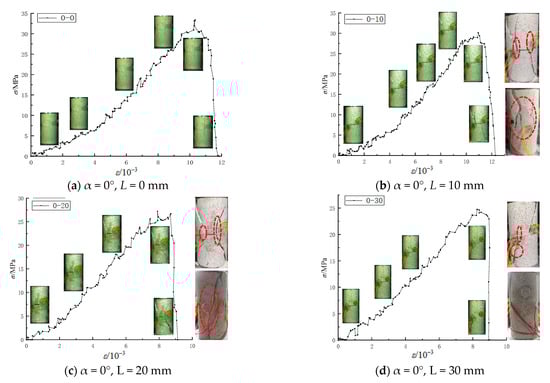
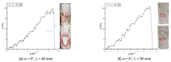
Figure 8.
Stress–strain curves and crack propagation mechanism.
Based on the above analysis, it was concluded that the complete specimen was different from the perforated crack specimen. The surface crack propagation mode was that the defect zone and the intact zone of the specimen crack initiation, respectively, expanded separately and converged locally. The failure characteristics were as follows: (1) The surface crack tip had a unique bidirectional initiation mode. (2) When the two regional cracks spread to a certain area, the local cracks coalesced and combined with the failure. (3) The crack propagation in one region led to the non-uniform deformation of the whole specimen, which led to a change in the stress environment of the crack in the other region, leading to the mutation of the crack propagation mechanism. (4) When the stress of the rock specimen reached the failure limit of the two areas at the same time, the main failure crack of the two areas was generated in a short time.
4.4. AE Characteristics
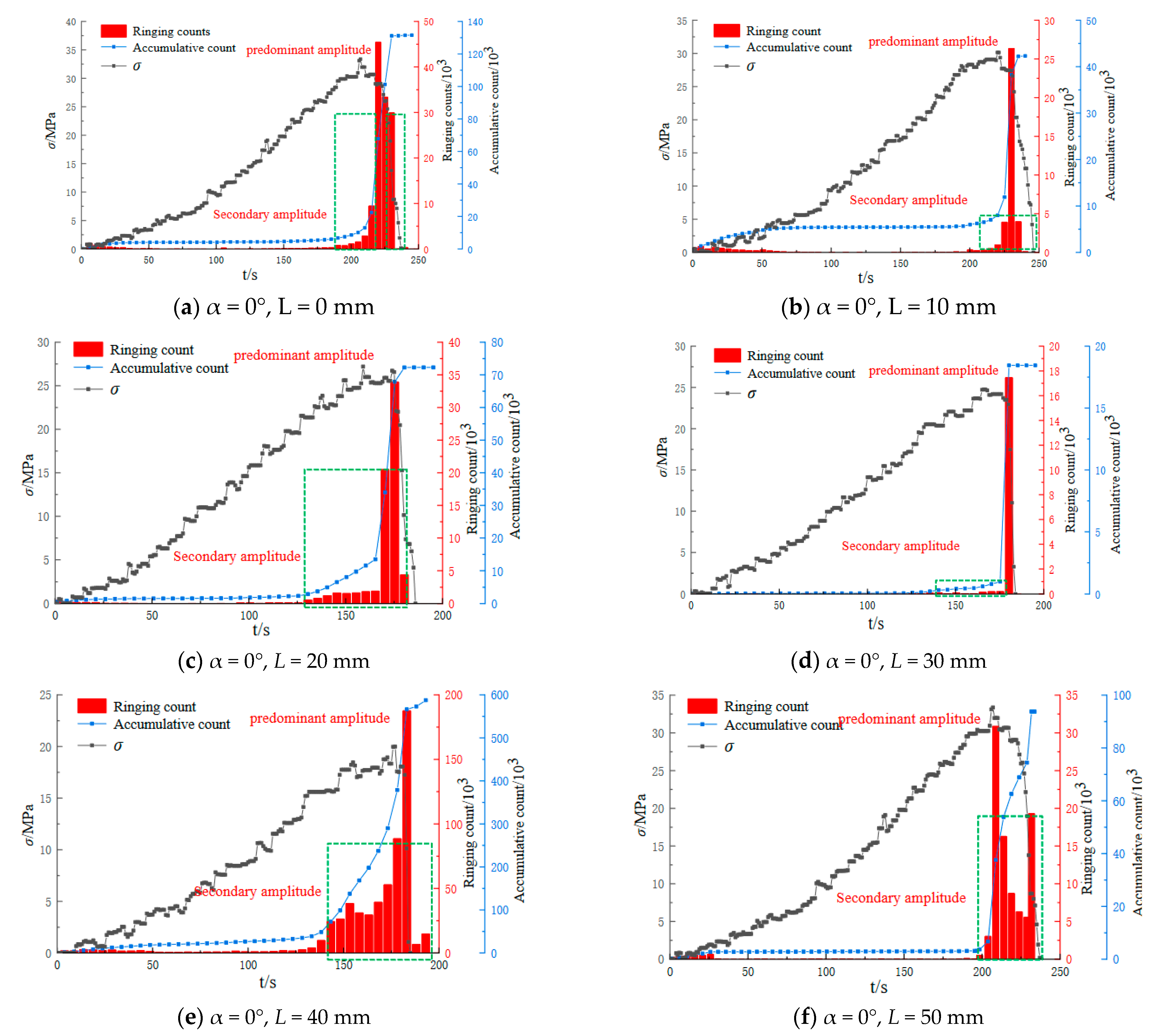
The fracture process of the white sandstone specimens was also monitored by an acoustic emission system. The white sandstone specimens monitored were 0–0, 0–10, 0–20, 0–30, 0–40, and 0–50. The curves of stress, acoustic emission ring count, and cumulative ring count versus time during fracture were obtained for all test pieces, as shown in Figure 9. As with the typical total stress–strain curve of rock and the four stages of deformation and failure, the AE of rock deformation and failure could be divided into four characteristic zones: (1) The compaction stage of rock pore and fracture, during which there were few AE events. (2) At the stage of elastic deformation and microcrack initiation, the area was relatively quiet and no AE events occurred. (3) The AE event rate increased steadily in the macro fracture propagation stage. (4) In the stages of fracture penetration and rock failure, the instantaneous release of energy storage led to a sharp increase in AE events.
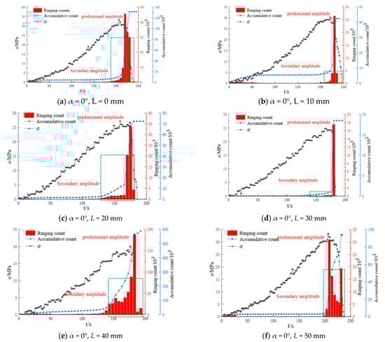
Figure 9.
Relationship curves of stress, acoustic emission ringing count, and cumulative ringing count versus time.
The fracture depth had a significant influence on the failure mode of the white sandstone specimens. The test results showed that with the increasing crack depth, the failure mode of the specimen transitioned from tensile failure to shear failure. The failure mode of the specimen directly determined the variation law of acoustic emission signals in the process of rock fracture. It can be seen in Figure 9 that the AE ringing count of the specimens mainly occurred in the crack and pore compaction stage of the first stage of the rock failure process and the non-uniform deformation stage of the macro crack penetration stage of the third stage. The AE ring count of the rock reached the maximum during the third stage of main crack penetration. The maximum ringing counts for specimens 0–0, 0–10, 0–20, 0–30, 0–40, and 0–50 were 4516, 2635, 33,880, 17,453, 187,635, and 30,868, respectively. It could be concluded that the ringing counts of test pieces 0–0, 0–10, 0–20, 0–30, and 0–50 were close to each other during the failure process, and the maximum ringing counts of the 0–40 test pieces were much higher than those of other specimens. Through analysis of the destruction process of the 0–40 specimens, it was found that the acoustic emission probe was arranged in the rock-burst area of the specimen. The reason for rock-burst is that the asymmetric deformation of the specimen leads to stress concentration in the region, which makes the region instantly gather and produce energy far beyond its own energy storage limit. At the same time, there is no macroscopic crack or large deformation that leads to the transfer and release of the accumulated energy in the region before the failure.
Comparative analysis of Figure 9 and Figure 10 shows that the secondary amplitudes of the complete specimen (a) and the through-crack specimen (f) were mainly concentrated after the maximum main amplitude, while the secondary amplitudes of the surface crack specimens (b)–(d) were mainly concentrated before the maximum main amplitude. Through analysis of the stress curve, it could be concluded that there were obvious post-peak stress curves in specimens (a) and (f), while the post-peak curves of specimens (b)–(d) were steep and the post-peak stress basically disappeared. The exact match between the stress curve track and the AE ringing count distribution law proved the reliability of the research data and results. The reason for this phenomenon was that both the complete specimen and the horizontal through-crack specimen were symmetrical structures, and their failure forms were mainly symmetrical failures. The symmetrical failure structures produced after reaching the maximum principal stress still had a certain stability and resistance to deformation. However, the failure process of specimens (b)–(d), the asymmetrically defective rock specimens, was different from the whole process of integrated failure in the intact rock specimens and the whole process of integrated failure in the connected rock specimens dominated by through fracture. The failure forms were as follows: in the early stage, the local failure of the intact area and fractured area; in the middle stage, the collaborative failure of the fusion of the two destruction regions; in the later stage, the dominant fracture surfaces formed by the combination of the two regions were destroyed as a whole. Therefore, the main fracture surface generated by the failure of specimens (a) and (f) was a two-dimensional plane, and the main fracture surface of surface crack specimens (b)–(d) was a three-dimensional curved surface. The failure mode of surface fracture was the asymmetrical stage failure of the subregion. The different failure modes of each part led to the different failure forms of each part after failure, and finally led to the asymmetry and weak stability characteristics of the whole structure after failure. Therefore, the failure mode of the surface crack resulted in a large number for the pre-peak ringing counts of surface crack specimens (b)–(d), while there was almost no residual stress or post-peak ringing counts.
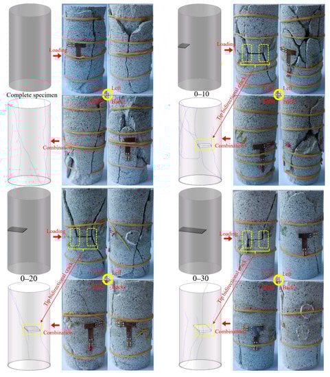
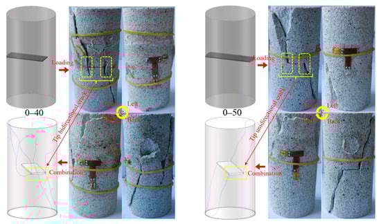
Figure 10.
Three-dimensional fracture distribution diagrams of rock specimens.
4.5. Mechanism of 3D Crack Growth
The propagation mechanism of rock cracks is one of the key components of the rock damage constitutive model. At present, the assumption of strain equivalence is widely used in typical geometric damage models of rock. Through the modified model, the whole process of rock deformation and fracture can be well simulated, and the common problems of rock specimen pre-peak deformation have been well explained [32]. However, there are still some defects and limitations in the description of the complex mechanical properties of heterogeneous rock specimens with defects, especially in the description of the post-peak failure characteristics of a heterogeneous fractured rock specimen.
The variation in the boundary conditions of the front edges of the three straight cracks in the specimens led to the differences in the failure forms of the specimens. By changing the boundary conditions of the straight front edge of an asymmetric crack, different failure modes of the front edge of the crack can be studied. The difference in failure modes leads to different crack propagation modes. Through a comparison of (b)–(f) in Figure 10 it could be concluded that the crack tip of specimens (b)–(e) was bidirectional propagation, while the crack tip of specimen (f) was unidirectional propagation.
The introduction of a rock crack propagation mechanism is the key factor to solve the limitations of the classical rock theoretical model. As shown in Figure 10, six rock experimental models with different damages were selected for laboratory tests. From the three-dimensional crack propagation model of rock specimens, it can be concluded that the propagation mechanism of failure cracks in different rock specimens with different damage degrees is quite different. The crack propagation mechanism plays a decisive role in the post-peak deformation and failure of rock. Therefore, it is of great significance to explore the three-dimensional crack growth mechanism of different damaged rocks. Through the structural symmetry of rock specimens a and f, we obtained a more symmetrical and unified three-dimensional propagation crack. For the unsymmetrical structure specimens with surface cracks, specimens b–d, the failure mode had significant complexity and asymmetry. Through analysis, it was concluded that the synergetic failure of the undamaged and damaged parts of the surface rock specimens was the action mechanism of the three-dimensional crack propagation results. At the same time, taking the boundary condition C of the front edge of the crack as a variable, it was concluded that the three-dimensional deformation and failure mechanism of a rock specimen had a boundary effect. The three-dimensional propagation mechanism of different damaged rock specimens was expounded theoretically through experimental analysis. The quantitative description of the three-dimensional crack growth mechanism of different damaged rock specimens will be the focus of follow-up work.
5. Engineering Significance
These tests showed that a surface crack will reduce the strength of rock specimens. The crack and its adjacent intact rock specimens are not independent of each other, and there is a cooperative effect of deformation and failure. The surface crack specimen was damaged to form an integral three-dimensional asymmetric structure, which was characterized by weak stability and low post-peak stress intensity. In the process of asymmetric deformation and failure, a high-density energy region will be generated. The surface-fractured rock mass has strong rock-burst characteristics under specific boundary conditions. The surface rock mass is the primary object of engineering damage. The test results indicated that for rock surrounding engineering, it is necessary to not only consider the characteristics of the rock mass surrounding the surface fissure, but also to comprehensively analyze its characteristics with the surrounding complete rock mass. The asymmetric failure of surface-fractured surrounding rock will weaken the self-stability ability of damaged rock mass. Studying the failure mechanism of surface-fractured rock mass can increase the understanding of the failure mechanism of rock surrounding engineering, which is of great significance for improving engineering protection, reducing the cost of protection, improving the efficiency of protection, and enhancing the accuracy of engineering risk warning.
6. Conclusions
- (1)
- According to the failure mechanism of the three-dimensional failure model of the surface-damaged specimen, the surface crack specimen was divided into a damaged rock specimen and an undamaged rock specimen, and a three-dimensional mechanical model of the surface crack specimen based on the COFPDP theory was established. The failure mechanisms of fracture fronts A, B, and C in the damaged rock specimen were analyzed. In the uniaxial experiment, the initiation mode and propagation mechanism of the fracture front of the surface horizontally fractured rock specimens were related to the lengths of the A and B fracture fronts.
- (2)
- Through comparative analysis of six kinds of specimens, it was concluded that the complete specimen was an overall failure, that the failure of the surface crack specimen was jointly guided by the surface crack and the complete part of the rock specimen, and that the failure of the penetrating crack specimen was controlled by the penetrating crack. The different failure modes of the three types of rock specimens led to very large differences in the whole failure process, which were mainly reflected in the structural stability and residual strength of the post-peak failure rock specimens. At the same time, the appearance of three-dimensional curved fissures confirmed the necessity of introducing the COFPDP theory of three-dimensional fissure extension.
- (3)
- The surface-fractured rock specimen presented the propagation form of a tip crack, which is different from a penetrating crack. In the surface-fractured rock specimen, the crack tip was bidirectionally expanded in the upper and lower directions, while the crack tip in the through-crack specimen was unidirectionally expanded. The failure mode was caused by the support and failure lag of the intact rock specimen in the corresponding region of surface fracture.
- (4)
- With an increase in the crack depth of the rock specimen, the failure mode of the specimen transitioned from tensile failure to shear failure. The failure modes were as follows: The complete standard specimen had tensile failure. The surface-fractured rock specimen with a fracture depth of 10 mm had mainly tensile failure, and local shear failure occurred. The surface-fractured rock specimen with a fracture depth of 20 mm had tensile–shear failure, and the fracture surface of the specimen was an X-type failure crack. The surface-fractured rock specimen with a fracture depth of 30 mm had tensile–shear failure; the shear cracks generated in the fracture zone of the specimen and the tensile cracks generated in the complete zone could cause the integrity of the specimen. The failure modes of the surface-fractured rock specimen with a crack depth of 40 mm and the penetrating fractured rock specimen with a crack depth of 50 mm both had shear failure dominated by cracks.
Author Contributions
Conceptualization, H.G.; Methodology, W.Y. and H.G.; Validation, W.Y.; Formal analysis, H.G. and K.L.; Investigation, Bao Pan; Resources, W.Y. and H.G.; Writing—original draft, H.G.; Writing—review & editing, W.Y., H.G. and K.L.; Supervision, B.P. All authors have read and agreed to the published version of the manuscript.
Funding
This study was supported by the National Natural Science Foundation of China (Grant Nos. 52174076, 51974117) and the Postgraduate Scientific Research Innovation Project of Hunan Province (Grant No. CX20210984).
Data Availability Statement
The experimental test data used to support the findings of this study are available from the corresponding author upon request.
Conflicts of Interest
The authors declare that there is no conflict of interest regarding the publication of this article.
References
- Qian, Q. New progress of rock engineering technology in China. Strateg. Study CAE 2010, 12, 37–48. [Google Scholar]
- She, S.; Lin, P. Some developments and challenging issues in Rock engineering field in China. Chin. J. Rock Mech. Eng. 2014, 33, 433–457. [Google Scholar]
- Fan, H.; Lu, Y.; Hu, Y.; Fang, J.; Lv, C.; Xu, C.; Feng, X.; Liu, Y. A Landslide Susceptibility Evaluation of Highway Disasters Based on the Frequency Ratio Coupling Model. Sustainability 2022, 14, 7740. [Google Scholar] [CrossRef]
- Zhu, C.; Long, S.; Zhang, J.; Wu, W.; Zhang, L. Time Series Multi-Sensors of Interferometry Synthetic Aperture Radar for Monitoring Ground Deformation. Front. Environ. Sci. 2022, 10, 952. [Google Scholar] [CrossRef]
- Cheng, J.; Wang, B.; Fan, T.; Wang, Y.; Jiang, B. Typical application scenes and key technologies of coal mine geolog-ical transparency. Coal Sci. Technol. 2022, 50, 1–12. [Google Scholar]
- Yuan, Z.; Zhao, J.; Li, S.; Jiang, Z.; Huang, F. A Unified Solution for Surrounding Rock of Roadway Considering Seepage, Dilatancy, Strain-Softening and Intermediate Principal Stress. Sustainability 2022, 14, 8099. [Google Scholar] [CrossRef]
- Wu, H.; Jia, Q.; Wang, W.; Zhang, N.; Zhao, Y. Experimental Test on Nonuniform Deformation in the Tilted Strata of a Deep Coal Mine. Sustainability 2021, 13, 13280. [Google Scholar] [CrossRef]
- Li, J.; Yuan, W.; Li, H.; Zou, C. Study on dynamic shear deformation behaviors and test methodology of sawtooth-shaped rock joints under impact load. Int. J. Rock Mech. Min. Sci. 2022, 158, 105210. [Google Scholar] [CrossRef]
- Yu, W.; Wu, G.; An, B.; Wang, P. Experimental Study on the Brittle-Ductile Response of a Heterogeneous Soft Coal Rock Mass under Multifactor Coupling. Geofluids 2019, 2019, 5316149. [Google Scholar] [CrossRef]
- Yu, W.; Li, K. Deformation Mechanism and Control Technology of Surrounding Rock in the Deep-Buried Large-Span Chamber. Geofluids 2020, 2020, 8881319. [Google Scholar] [CrossRef]
- Yang, X.X.; Sun, D.K.; Jing, H.W. Morphological features of shear-formed fractures developed in a rock bridge. Eng. Geol. 2020, 278, 105833. [Google Scholar] [CrossRef]
- Yang, S.; Dai, Y.; Han, L.; He, Y.; Li, Y. Uniaxial compression experimental research on deformation and failure properties of brittle marble deformation and failure properties of brittle marble. Chin. J. Rock Mech. Eng. 2009, 28, 2391–2404. [Google Scholar]
- Yang, S.Q.; Liu, X.R. Experimental investigation on dilatancy behavior of marble with pre-existing fissures under different confining pressures. Chin. J. Geotech. Eng. 2012, 34, 2188–2197. [Google Scholar]
- Zhao, Y.; Zhang, L.; Asce, F.; Wang, W.; Cheng, G. Experimental Study on Shear Behavior and a Revised Shear Strength Model for Infilled Rock Joints. Int. J. Geomech. 2020, 20, 04020141. [Google Scholar] [CrossRef]
- Zhao, Y.; Zhang, L.; Asce, F.; Liao, J.; Tang, L. Experimental Study of Fracture Toughness and Subcritical Crack Growth of Three Rocks under Different Environments. Int. J. Geomech. 2020, 20, 04020128. [Google Scholar] [CrossRef]
- Liu, X.-R.; Yang, S.-Q.; Huang, Y.-H.; Cheng, J.-L. Experimental study on the strength and fracture mechanism of sandstone containing elliptical holes and fissures under uniaxial compression. Eng. Fract. Mech. 2019, 205, 205–217. [Google Scholar] [CrossRef]
- Yu, W.; Wu, G.; Pan, B.; Wang, C.; Li, K.; Liao, Z. Laboratory and field investigations of different bolting configurations for coal mine roadways in weak coal strata. Bull. Eng. Geol. Environ. 2021, 80, 8995–9013. [Google Scholar] [CrossRef]
- Yu, W.; Wu, G.; Pan, B.; Wu, Q.; Liao, Z. Experimental Investigation of the Mechanical Properties of Sandstone-Coal-Bolt Specimens with Different Angles under Conventional Triaxial Compression. Int. J. Geomech. 2021, 21, 04021067. [Google Scholar] [CrossRef]
- Yu, W.; Li, K.; Liu, Z.; An, B.; Wang, P.; Wu, H. Mechanical characteristics and deformation control of surrounding rock in weakly cemented siltstone. Environ. Earth Sci. 2021, 80, 337. [Google Scholar] [CrossRef]
- Zhao, Y.; Tang, J.; Chen, Y.; Zhang, L.; Wang, W.; Wan, W.; Liao, J. Hydromechanical coupling tests for mechanical and permeability characteristics of fractured limestone in complete stress–strain process. Environ. Earth Sci. 2017, 76, 24. [Google Scholar] [CrossRef]
- Zhao, Y.; Zhang, C.; Wang, Y.; Lin, H. Shear-related roughness classification and strength model of natural rock joint based on fuzzy comprehensive evaluation. Int. J. Rock Mech. Min. Sci. 2020, 137, 104550. [Google Scholar] [CrossRef]
- Chen, W.; Wan, W.; Zhao, Y.; Peng, W. Experimental Study of the Crack Predominance of Rock-Like Material Containing Parallel Double Fissures under Uniaxial Compression. Sustainability 2020, 12, 5188. [Google Scholar] [CrossRef]
- Zhu, J.-W.; Cao, W.-S.; Xue, G.-H.; Xue, W.-J.; Zhou, K. Experimental study and numerical simulation of propagation and coalescence-process of a single three dimensional flaw in rocks. J. China Coal Soc. 2013, 38, 411–417. [Google Scholar]
- Fu, J.W.; Chen, K.; Zhu, W.S.; Zhang, X.Z.; Li, X.J. Progressive failure of new modelling material with a single internal crack under biaxial compression and the 3-D numerical simulation. Eng. Fract. Mech. 2016, 165, 140–152. [Google Scholar] [CrossRef]
- Li, S.; Li, T.; Wang, G.; Bai, S. CT real-time scanning tests on rock specimens with artificial initial crack under uniaxial conditions. Chin. J. Rock Mech. Eng. 2007, 26, 484–492. [Google Scholar]
- Ju, Y.; Xie, H.; Zheng, Z.; Lu, J.; Mao, L.; Gao, F.; Peng, R. Visualization of the complex structure and stress field inside rock by means of 3D printing technology. Chin. Sci. Bull. 2014, 59, 5354–5365. [Google Scholar] [CrossRef]
- Ju, Y.; Liu, P.; Ren, Z.; Mao, L.; Chiang, F.P. Characterization of stress field evolution during 3D internal fracture propagation using additively printed models and frozen stress techniques. Theor. Appl. Fract. Mech. 2021, 111, 102870. [Google Scholar] [CrossRef]
- Zhu, J.; Zhou, T.; Liao, Z.; Sun, L.; Li, X.; Chen, R. Replication of internal defects and investigation of mechanical and fracture behaviour of rock using 3D printing and 3D numerical methods in combination with X-ray computerized tomography. Int. J. Rock Mech. Min. Sci. 2018, 106, 198–212. [Google Scholar] [CrossRef]
- Zhou, T.; Zhu, J.B. Identification of a Suitable 3D Printing Material for Mimicking Brittle and Hard Rocks and Its Brittleness Enhancements. Rock Mech. Rock Eng. 2017, 51, 765–777. [Google Scholar] [CrossRef]
- Li, S. Fracture Mechanics; Science Press: Beijing, China, 2015; pp. 278–313. [Google Scholar]
- ASTM D7012; Standard Test Methods for Compressive Strength and Elastic Moduli of Intact Rock Core Specimens under Varying States of Stress and Temperatures. American Society for Testing and Materials: Philadelphia, PA, USA, 2017.
- Chao, Z.; Yun, B. Establishment and application of parametric geometrical damage model of rocks. Rock Soil Mech. 2020, 41, 3899–3909. [Google Scholar]


Disclaimer/Publisher’s Note: The statements, opinions and data contained in all publications are solely those of the individual author(s) and contributor(s) and not of MDPI and/or the editor(s). MDPI and/or the editor(s) disclaim responsibility for any injury to people or property resulting from any ideas, methods, instructions or products referred to in the content. |
© 2023 by the authors. Licensee MDPI, Basel, Switzerland. This article is an open access article distributed under the terms and conditions of the Creative Commons Attribution (CC BY) license (https://creativecommons.org/licenses/by/4.0/).