Article

Formula Derivation and Analysis of the Seismic Lateral Pressure of Squat Silos

School of Civil Engineering, Central South University, Changsha 410075, China
*
Author to whom correspondence should be addressed.
Sustainability 2023, 15(6), 5098; https://doi.org/10.3390/su15065098
Submission received: 17 January 2023 / Revised: 12 February 2023 / Accepted: 3 March 2023 / Published: 13 March 2023
(This article belongs to the Section Sustainable Engineering and Science)

Abstract

:
The silo lateral pressure is an important parameter in the seismic design of squat silo. However, there is no exact theoretical calculation formula in the current silo code and the existing literature. The current study aimed to directly derive a new formula for calculating the seismic lateral pressure of squat silos in a simplified way. Firstly, based on Coulomb theory, regarded the silo as a special curved retaining wall and took the sliding wedge unit as the study object. Secondly, used the pseudo-static method and the rotating seismic angle method to simplify seismic forces and perform limit equilibrium analysis to derive the calculation formula. Finally, we verified the proposed formula by numerical simulation and parametric analysis. The results showed that silo wall friction could not be ignored, while the material cohesion is small enough to be ignored during engineering. For a large-diameter squat silo in a flat stack condition, a change in the radius has less influence on the side pressure strength, and the squat silo can be simplified as a linear retaining wall, while the lateral pressure strength increases as the radius increases in the conical stack condition. In addition, the measurement data and simulation calculation were close to the formula calculation, indicating the superiority of the new formula. These research results could provide a reference basis for improving the calculation of the seismic lateral pressure of silo specifications.

1. Introduction

As a special kind of curved retaining wall [1], silos have been widely used in industry and agriculture, but many silos have been seriously damaged by high silo-side pressure during earthquakes. Therefore, to ensure silo safety and resilience, the silo lateral pressure under earthquake conditions should be considered, which will have a certain reference value for improving the seismic design of squat silos.
Many researchers have studied the silo lateral pressure, and some have proposed theoretical analysis methods. Janssen’s theory [2], for example, introduced the lateral pressure coefficient to derive the static silo side pressure. Airy’s theory [3] introduced the concept of the sliding wedge in geomechanics to the calculation of silo lateral pressure. Veletsos and Younan’s theory [4,5] used a simplified approximation method for seismic analysis when taking bulk material effects into account in both static and dynamic cases. The classical Coulomb and Rankine theory [6] was introduced later into silo analysis. And the famous M-O theory [7] was well known in the calculation of the simplified seismic earth pressure. Most studies [8,9,10,11,12] since then have been based on these theories, but almost all have focused on the study of lateral pressure in the static and unloaded states. Some researchers have used experimental methods; Weixng SHI [13] used a scale model of a coal storage silo and simulated the seismic response of the silo using a shaking table test. Fang Yuan [14] conducted six tests on three large-diameter grain silos to obtain the stored material lateral pressure and distribution characteristics. Lujian Zhang [15] also conducted seismic shake tests and analyzed the dynamic characteristics and the lateral pressure distribution during an earthquake, then concluded that the seismic lateral pressure was larger than the static lateral pressure and much larger than the silo code value. Hang J [16] conducted a series of shaking table tests on three models with different silo-filling conditions to investigate the interaction law of the wheat material and steel silo structure system. Gandia R M [17] tested six different types of silo geometries and obtained the resulting pressures in a full-scale silo from assays performed on a test station using a free-flowing product. Some researchers have used numerical simulation methods, Livaoglu R [18] used a simplified seismic analysis procedure to estimate the distribution and the magnitude of dynamic material pressures on ground-supported silos and incorporated a three-dimensional finite element model to represent a more realistic structure. Djelloul Z [19] investigated the reliability of the European guidelines employed for designing steel silos subjected to seismic excitations through full finite element analysis of a flat-bottomed slender steel silo, taking into account the nonlinear time history analysis, wall flexibility, geometric imperfections, soil-structure interaction, and multidirectional components. Shunying JI [20] studied the granular silo flow, considering gravity as the sole driving force to demonstrate the influence of external pressure. And Temsah Y [21] simulated the structural response of grain silos under blast loads and defined the explosion magnitude and the structural state of the remaining silos. Weiwei SUN [22] analyzed the pressure evolution under loading and unloading conditions and Hang JING [23] studied the side pressure distribution based on the Duncan-Zhang model. These works of research were mainly based on finite element or discrete element methods to simulate the dynamic silo characteristics under different load conditions. In addition, it focused on the seismic performance of the reinforced concrete shear walls. Faraone G [24,25] established a numerical model capable of representing coupled shear–flexure interactions and validated it against tests conducted on three full-scale reinforced concrete walls, predicting the deformation and cracks pattern to provide insight into the likelihood of the impact of concrete damage. Almasabha G [26] studied a popular seismic force-resisting system consisting of rectangular concrete squat structural walls to improve its limitations in shear strength and drift ductility. The studies outlined above provide a reliable basis for the seismic design of structures.
In general, the existing literature has mainly focused on static characteristics based on the five theories mentioned above and the true seismic dynamic response according to shaking table tests or numerical simulation, such as silo displacement, reloading and unloading stiffness degradation, strain rate effect, etc. However, the existing studies and the silo codes [27,28,29] in different countries do not give a specific theoretical calculation formula for the silo lateral pressure during earthquakes, and they only consider multiplying an over-pressure coefficient on the calculation results of Janssen’s formula. Therefore, the current research focused on a simplified method to directly derive the calculation formula of the seismic lateral pressure in a squat silo, which will provide a reference basis for improving the calculation of the seismic lateral pressure in silo specifications. Unlike the existing literature on the dynamic and static response of silos, this paper regarded squat silos as curved retaining walls and focused on similar engineering problems to the study object, based on Coulomb theory. We then introduced the equivalent simplification of seismic forces using the pseudo-static method and the rotating seismic angle method to derive the calculation formula of the silo seismic lateral pressure before finally verifying the formula accuracy using example analysis and numerical simulation. The method flow chart is shown in Figure 1.

2. Derivation of the Calculation Formula

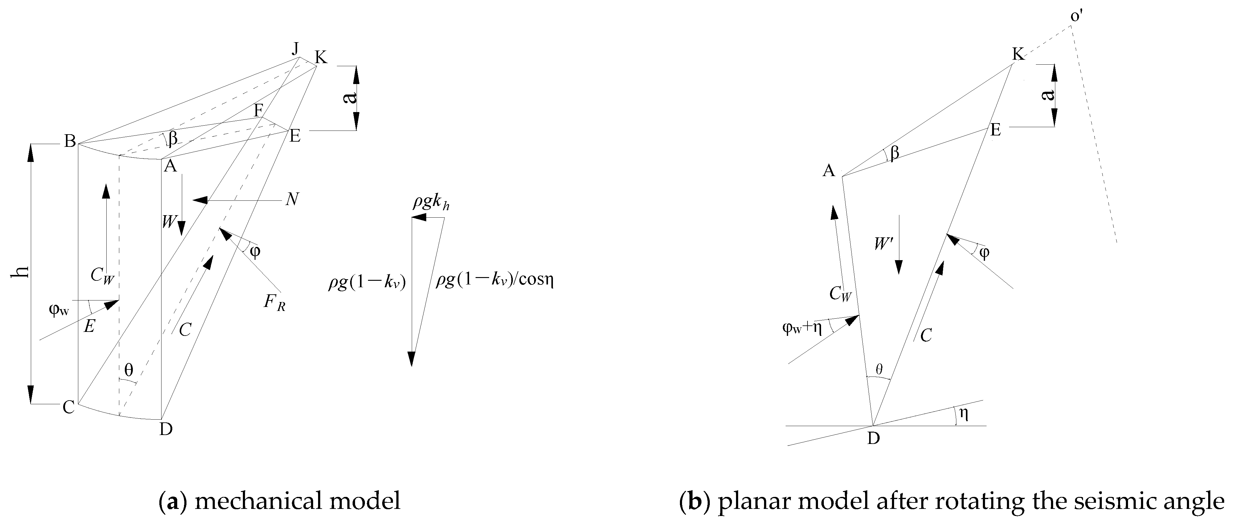
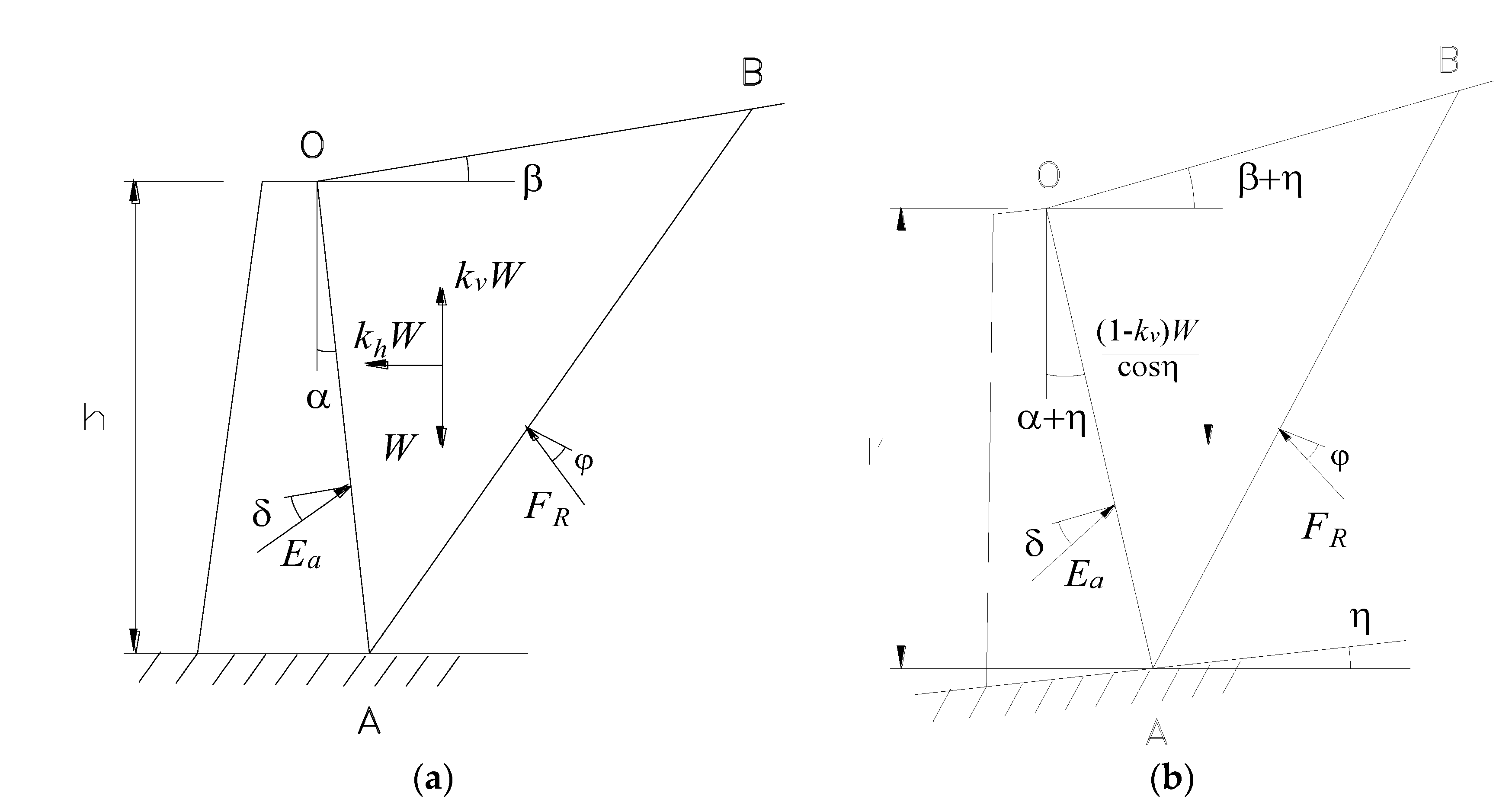
2.1. Calculation Model

We radially divided the squat silo into countless small sector units and took the sliding wedge enclosed by the unit arc length silo wall and the rupture surface as the study object, then assumed that the potential sliding rupture surface was a plane. The model was established, as shown in Figure 2a, based on the pseudo-static method to separately convert the horizontal and vertical seismic acceleration coefficient into horizontal and vertical inertia forces. We then applied them to the sliding wedge model. Considering that introducing a seismic angle can convert both gravity and seismic inertia forces into one force, we used the rotating seismic angle method to simplify the force analysis (see Figure 2b). Finally, we calculated the seismic lateral pressure of the squat silo based on the limit equilibrium analysis.
According to Figure 2 and based on classical Coulomb theory, β is the material inclination angle, the rupture surface of the sliding wedge is at an angle θ to the vertical direction, the silo seismic lateral pressure E is at an angle φ w to with the silo wall back, which is the external friction angle. F R is the reaction force on the rupture surface, which forms an internal friction angle φ with the rupture surface normal. N is the normal force on both sides of the sliding wedge, R is the silo radius, h is the silo height, and a is the corresponding height with β . The cohesion in surface ABCD is C w = c w S A B C D , with a direction of vertical upward. The cohesion in the rupture surface CDJK is C = c S C D J K , with the direction upward along the rupture surface. According to the rotational seismic angle method, the seismic angle η is the angle between the total volume force direction and the vertical direction of the sliding wedge during an earthquake, which is
tan η = k h ( 1 k v )
k h = a h / g k v = a v / g
where k h and k v are the horizontal and vertical seismic acceleration coefficients; a h and a v are the horizontal and vertical seismic acceleration; and g is the gravity acceleration.

2.2. Formula Derivation

Due to the symmetry of the silo structure, we ignored the force asymmetry caused by the horizontal seismic force to simplify the force analysis, then simplified the horizontal seismic force as a horizontal body force [30], i.e., the silo was assumed to be subjected to the most unfavorable load in all directions at the same time to achieve force symmetry, and then the corresponding calculation formula of the silo seismic lateral pressure was deduced by force analysis. According to the stacking situations of silo materials, we only analyzed the common flat stack condition and conical stack condition when the silo was in a full load state and also considered the silo material cohesion.
The conical stack working condition is illustrated in Figure 3a, and the calculation model is shown in Figure 2. The ruptured surface did not intersect with the silo center line. After rotating the sliding wedge counterclockwise by the seismic angle, the vertical gravity was transformed into the equivalent gravity, the wedge was balanced by the joint action of W , E , F R , C , C w and N , and these forces formed a force balance polygon, as shown in Figure 3b. According to the vertical and radial force balance of the sliding wedge, we have the following:
E sin ( φ ω + η ) + F R sin ( θ + φ η ) = W + 2 N sin 1 2 R sin η C cos ( θ η ) C w cos η
E cos ( φ ω + η ) F R cos ( θ + φ η ) = 2 N sin 1 2 R cos η C sin ( θ η ) + C w sin η
Combining the above two equations, we obtain
E = W cos ( θ + φ η ) + N R sin ( θ + φ ) C cos φ C w cos ( θ + φ ) sin ( θ + φ + φ ω )
where:
C w = c w S A B C D = c w h
C = c S C D J K = c h cos β cos ( θ + β ) ( 1 h sin θ cos β 2 R cos ( θ + β ) )
The equivalent gravity of the sliding wedge is
W = 1 k v γ cos η V = 1 k v γ cos η h 2 6 cos β sin θ cos ( θ + β ) 3 h R cos β sin θ cos ( β + θ )
The normal force on both sides of the sliding wedge is
N = 0 a / tan β k a γ 2 h a / tan β x a / tan β 2 d x = k a γ h 3 6 cos β sin θ cos β + θ
where k a is the silo lateral pressure coefficient
k a = cos 2 φ cos φ ω 1 + sin φ + φ ω sin ( φ β ) cos φ ω cos β 2
Substituting Equations (6)–(10) into Equation (5), we obtain
E = h 2 6 1 k v γ cos η cos β sin θ cos ( θ + φ η ) sin ( θ + φ + φ ω ) cos ( θ + β ) 3 h R cos β sin θ cos ( β + θ ) + k a γ h 3 6 R cos β sin θ sin ( θ + φ ) sin ( θ + φ + φ ω ) cos ( θ + β ) c w h sin ( θ + φ + φ ω ) c h cos β sin ( θ + φ + φ ω ) cos ( θ + β ) ( 1 h cos β sin θ 2 R cos ( θ + β ) )
We take the derivative of h in Equation (11) to obtain the seismic lateral pressure strength at depth z.
p a = d E d h = k a γ h 2 2 R cos β sin θ sin ( θ + φ ) cos φ ω sin ( θ + φ + φ ω ) cos ( θ + β ) + 1 k v γ h cos η cos β sin θ cos ( θ + φ η ) cos φ ω sin ( θ + φ + φ ω ) cos ( θ + β ) γ h 2 2 R 1 k v cos η cos 2 β sin 2 θ cos ( θ + φ η ) cos φ ω sin ( θ + φ + φ ω ) cos 2 ( θ + β ) c w cos φ ω sin ( θ + φ + φ ω ) c cos φ ω sin ( θ + φ + φ ω ) cos ( θ + β ) ( 1 h cos β sin θ R cos ( θ + β ) )
We use the trial method in Equation (11) to obtain the maximum value E m a x of the lateral pressure and its corresponding rupture angle θ c r , which satisfies the following relation:
d E d θ θ = θ c r = 0
The flat stack working condition is a special case of the conical stack working condition when the inclination angle β = 0 .

3. Example Analysis

Due to the lack of measured data on the silo side pressure during earthquakes, we set the horizontal and the vertical direction seismic acceleration coefficients to zero and then took the calculation results for comparison; that is, the new formula was used to calculate the static side pressure, aiming to initially verify the reasonableness of the new formula, and followed by further supplemental verification of the silo seismic lateral pressure with consideration of material cohesion through numerical simulation.

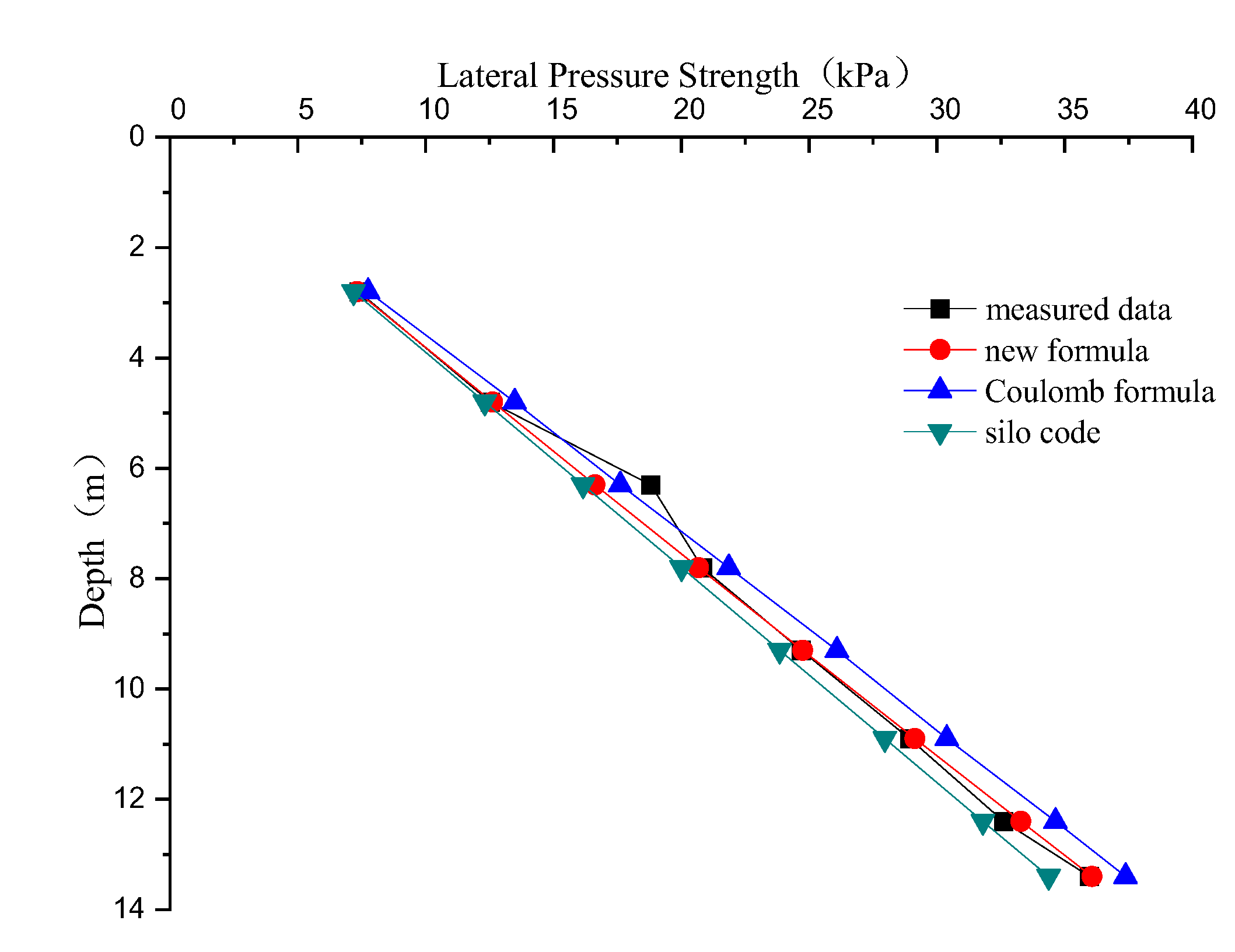
3.1. Flat Stack Working Condition

According to the literature [31], we took the silo height h = 13.77 m, radius R = 15 m, storage material (wheat) at γ = 7.85   kN / m 3 , internal friction angle φ = 25 ° , external friction angle φ w = 21.8 ° , and rupture angle θ c r = 40.6 ° from programming and using the trial method. We finally obtain calculation results that are shown in Table 1 and plotted in Figure 4.
As can be seen from Table 1 and Figure 4, the results calculated by the proposed new formula and the Coulomb formula were larger compared with the measured data, while the calculation results of the silo code were smaller, but overall there was very little difference among these four methods. The new formula in this paper was closer to the measured data, which initially verifies the new formula for use in the static calculation in the flat stack working condition.

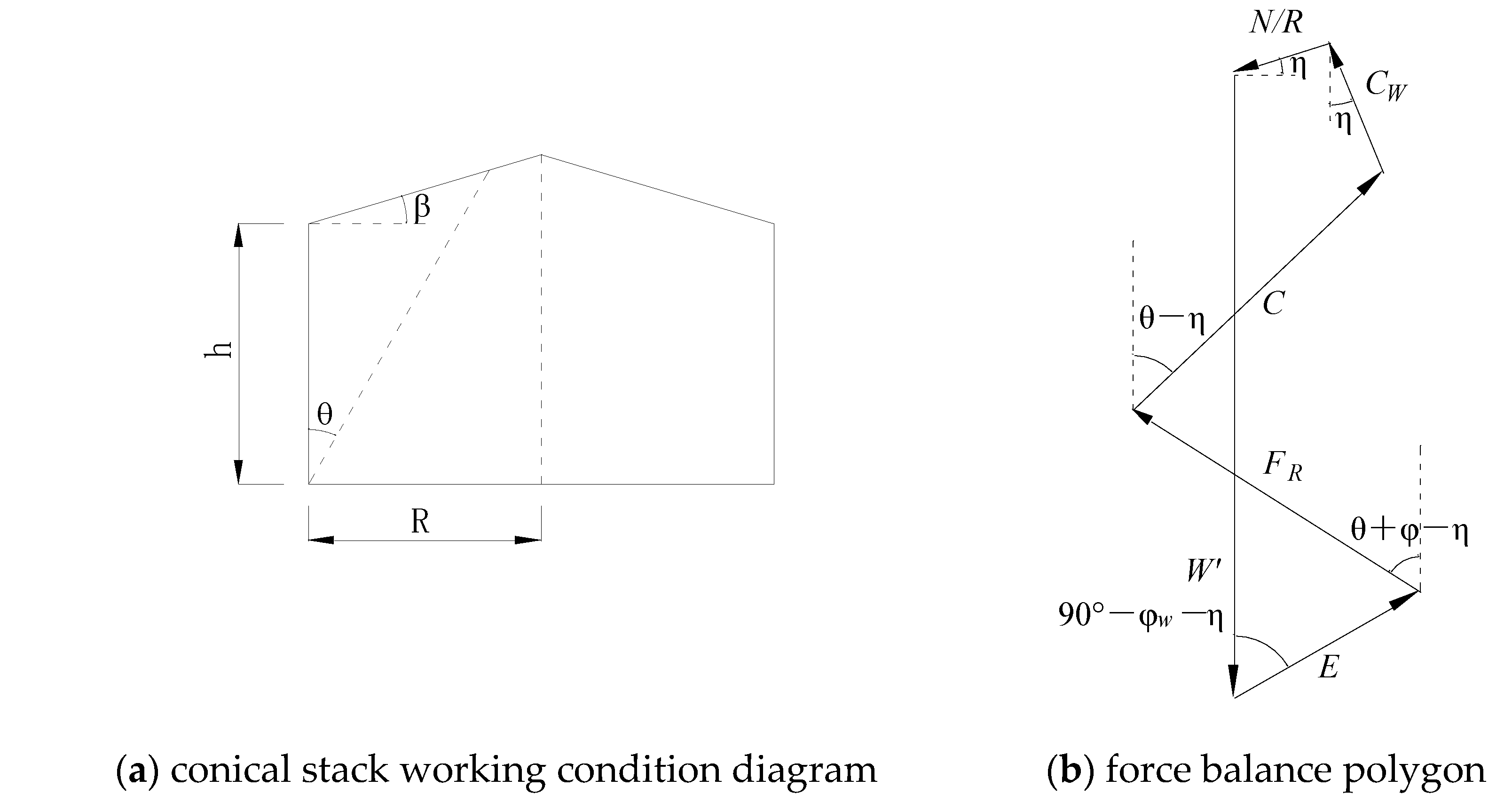
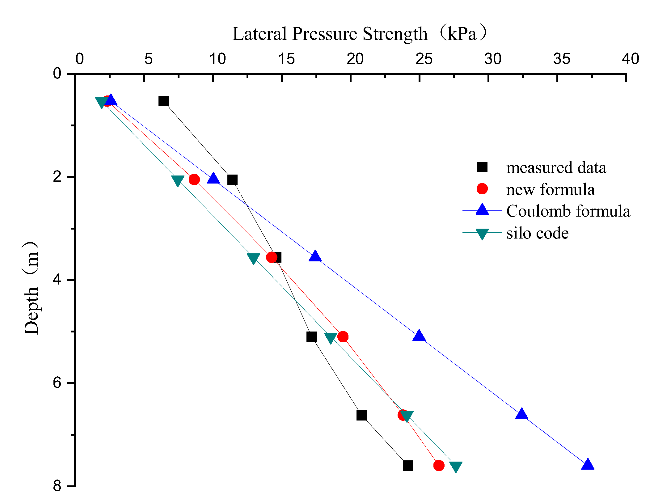
3.2. Conical Stack Working Condition

According to the literature [31], we took h = 8 m, β = 25 ° , and the calculated rupture angle θ c r = 39.5 ° . The other values were as above, and the results are shown in Table 2 and plotted in Figure 5.
As can be seen from Table 2 and Figure 5, the results calculated by the proposed new formula, the Coulomb formula, and the silo code were smaller in the upper part of the squat silo and larger in the lower part compared with the measured data. In general, the results of the silo specification were small and on the unsafe side. The results of the Coulomb formula were large and on the conservative side, and the results of the formula in this paper were closer to the actual measured data and, therefore, more applicable.

4. Numerical Simulation

4.1. The Numerical Simulation of Silo Side Pressure

We used ABAQUS to build the silo model. The concrete silo wall was simulated with a shell element (see Table 3), and the storage material was wheat (considering moisture with cohesion), which was simulated with a solid element by the Mohr-Coulomb model (see Table 4). We set the contact between the storage material and the silo wall as a flexible-rigid contact, then we applied the boundary conditions and simplified seismic force to simulate the seismic inertial force at the bottom of the squat silo. Since this paper represents the equivalence of the dynamic problem with a static problem, which does not essentially involve seismic dynamic response analysis, two loading levels of seismic acceleration were simply applied to the model for the two working conditions in the full material load condition to verify whether the formula derived by pseudo-static equivalent simplification of seismic forces was reasonable.

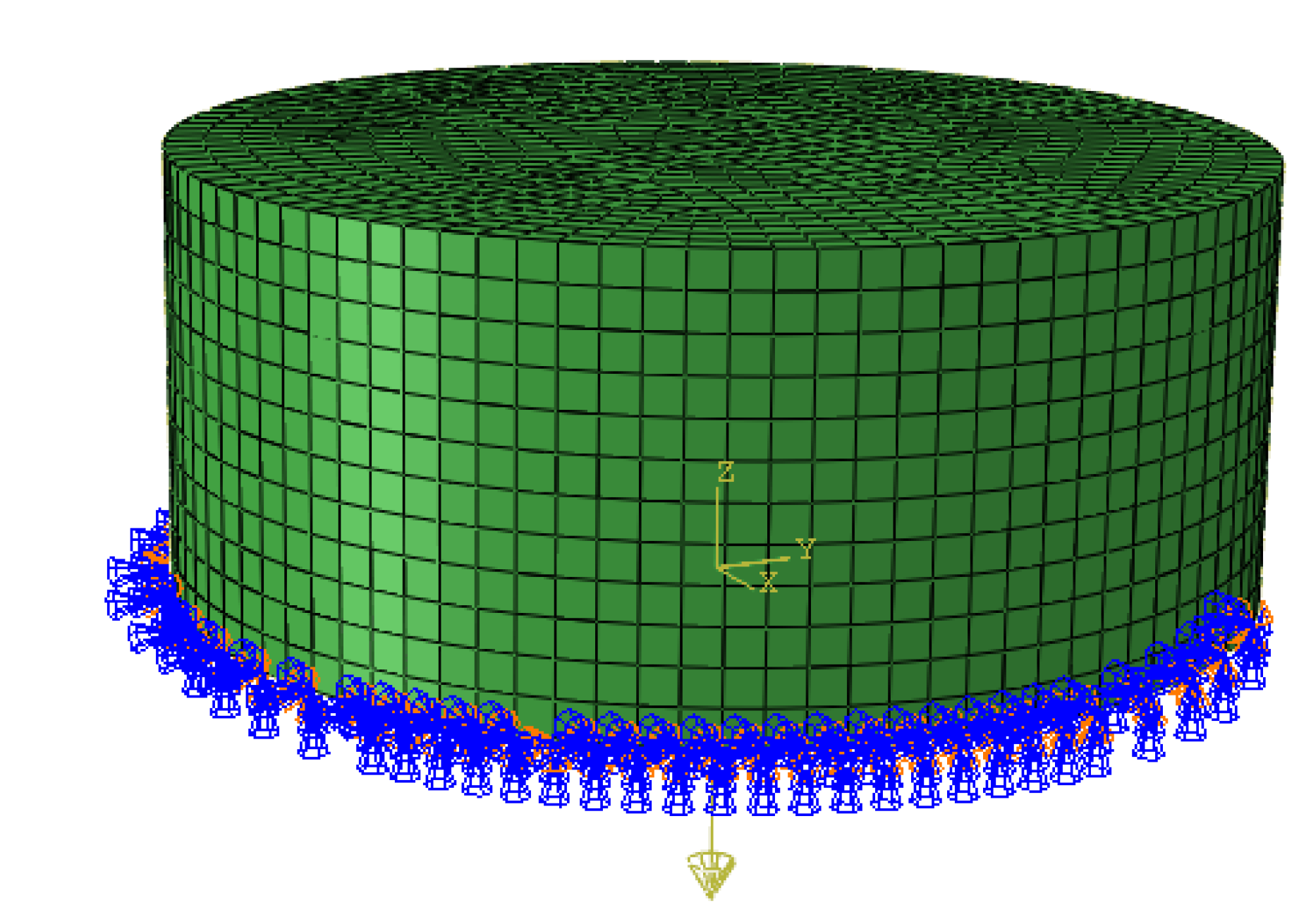
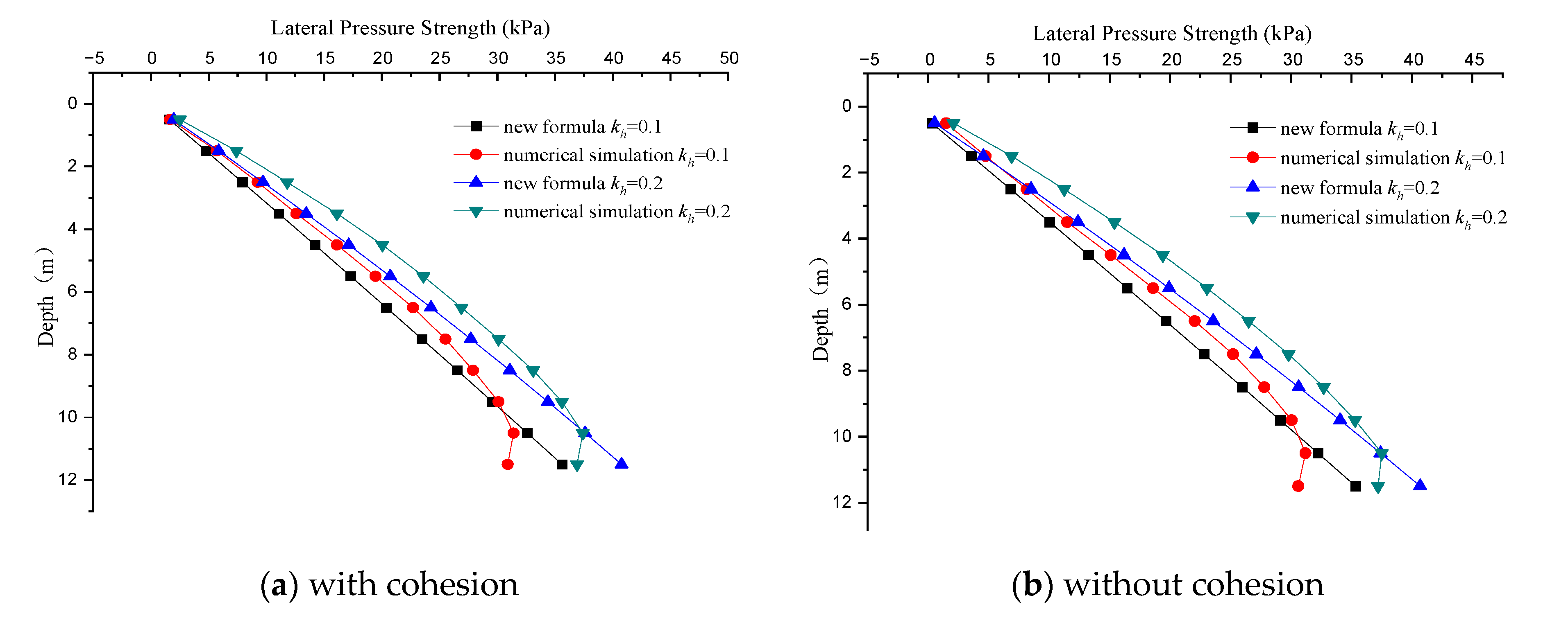
4.1.1. Flat Stack Working Condition

We took the silo radius R = 15 m and height h = 12 m (starting from 0.5 m and increasing by 1 m in turn, with a total of 12 measurement points). We took the general case of the horizontal seismic acceleration for and a h = 0.2 g ; that is, there was a horizontal seismic acceleration coefficient for k h = 0.1 and k h = 0.2 , using the proposed new formula to calculate the corresponding seismic lateral pressure of 242.31 kN and 285.01 kN, respectively. The floor silo does not consider the vertical seismic acceleration, so the seismic force in the model was simplified to the horizontal body force. The squat silo model was established, as shown in Figure 6, and the deformed shape of the modes is shown in Figure 7.
We considered the conditions under which wheat had cohesion or not, and we compared the side pressure strength distribution data calculated by the new formula and the numerical simulation in Figure 8, which was mainly to verify the effect of material cohesion and the accuracy of the new formula in the flat stack condition.
Figure 7 shows the Mises stress and deformed model of analysis step-2 in the flat stack condition (there is gravity in step-1, gravity, and simplified seismic forces in step-2). From Figure 8, it can be seen that the calculation results of the proposed new formula and the finite element simulation were closer to each other in the flat stack condition when considering the material cohesion or not, and the silo side pressure strength distribution calculated by the former was close to a straight line, while it was approximately a curve in the latter.
In the upper part of the squat silo, the results of this new method were smaller compared with the finite element simulation, but the impact on engineering practice was not significant, while in the lower part of the squat silo, the results of the proposed formula were bigger than the numerical simulation. The latter showed that the lateral pressure strength distribution curve at the silo bottom would abruptly show an inward reduction, which was due to the impact of rigid constraints on the silo bottom when modeling.

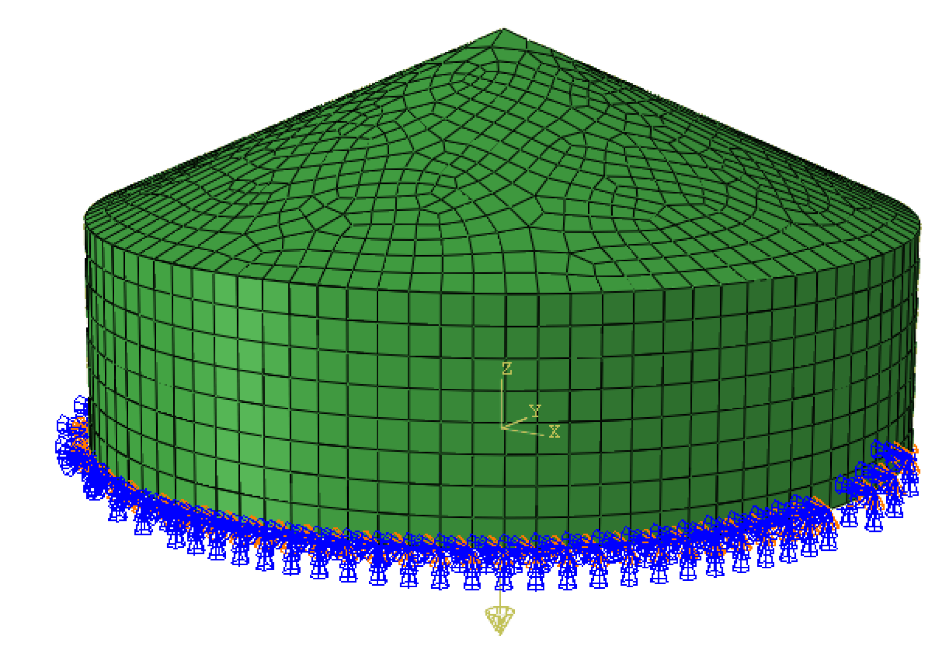
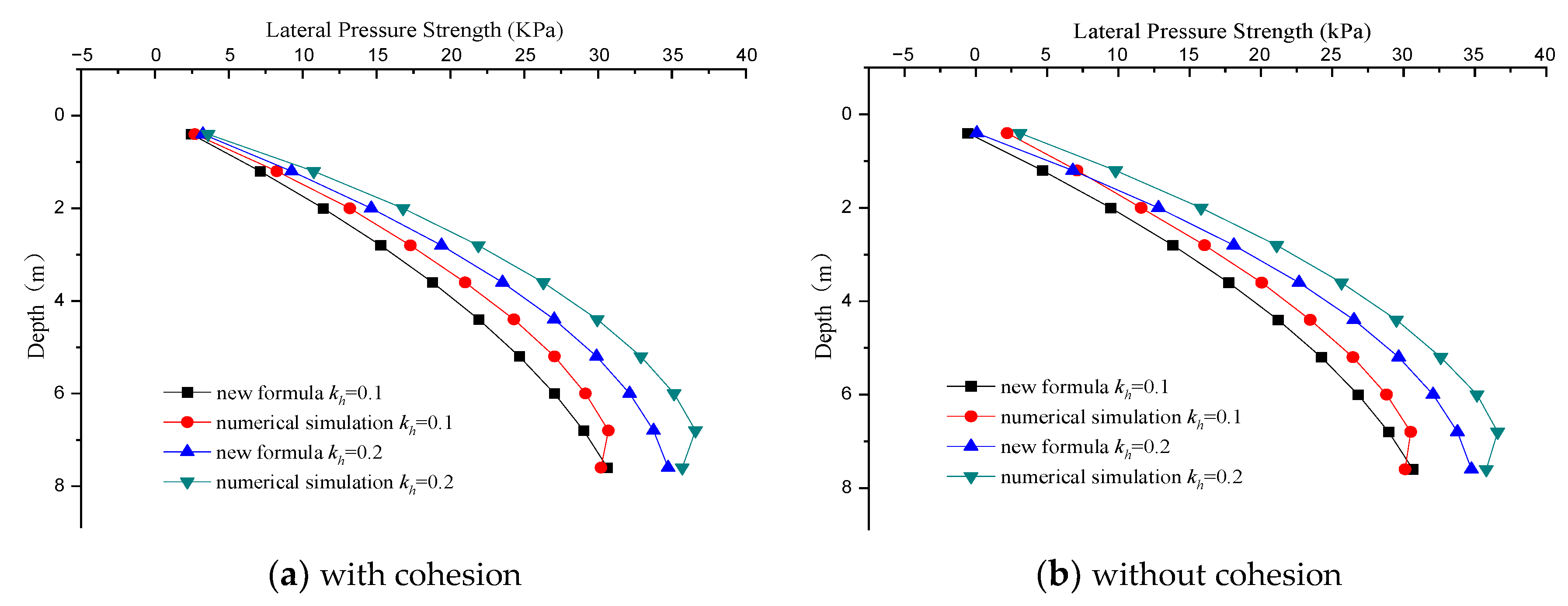
4.1.2. Conical Stack Working Condition

We took R = 15 m h = 8 m (starting from 0.4 m and increasing by 0.8 m in turn, with a total of 10 measurement points) and β = 25°. The other settings were as above. We established the silo model, as shown in Figure 9, and obtained the deformed model, as shown in Figure 10. We also considered the conditions under which wheat had cohesion or not, using the formula in this paper to calculate the case of the horizontal seismic acceleration coefficient k h = 0.1 and k h = 0.2 , respectively. The corresponding seismic lateral pressure strength is of 162.17 kN and 195.92 kN, and we compared the side pressure distribution data calculated by the new formula and the numerical simulation in Figure 11, which was mainly to verify the effect of material cohesion and the accuracy of the new formula in the conical stack condition.
Figure 10 shows the Mises stress and deformed model of analysis step-2 in the conical stack condition. According to Figure 7 and Figure 10, it can be seen that the storage material flowed as the simplified seismic forces increased. In addition, as can be seen from Figure 11, the calculation results of the proposed new formula and the finite element simulation were closer to each other in the conical stack condition, and the silo side pressure strength distribution calculated by the former was close to a parabola, while it was approximately a curve in the latter.
When considering the material cohesion, the calculation results of the new formula had negative values at a certain depth, which was due to the cohesion causing a critical cracking depth similar to the classical Coulomb earth pressure theory and leading to tension in the upper part, but the lateral pressure strength was not large and had no effect on the actual project. There the calculation results showed the same phenomenon in the lower part of the squat silo in these two working conditions.
When comparing Figure 8 with Figure 11, it can be seen that the calculation results of the formula in this paper fit well with the numerical simulation results, which had a certain reference and made up for the example analysis. In addition, the deviation of the theoretical results from the numerical simulation results was also larger with the increase in the horizontal seismic coefficient, which was due to the assumption that the silo material had a full load, and it meant the silo storage material would flow with the seismic force increase.

4.2. Parameter Analysis

Based on the study background and the parameters involved in the formula derivation, the material cohesion, silo radius, and external friction angle were selected for parametric analysis to determine their specific effects on the silo seismic lateral pressure, with the aim of providing a reference basis for the seismic silo design.

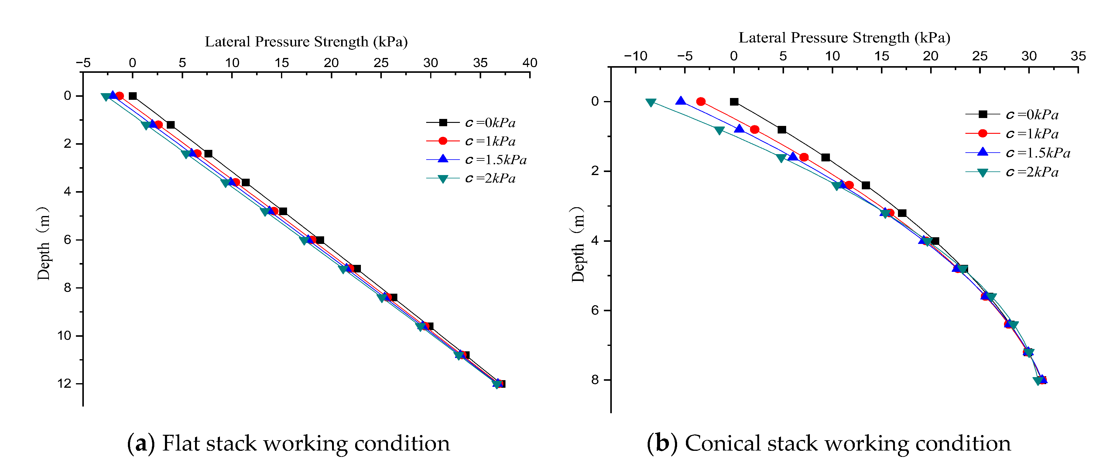
4.2.1. Effect of Material Cohesion on Silo Lateral Pressure during an Earthquake

The key values of the calculated parameters are shown in Table 5, and the other conditions were the same as above. For most of the storage materials, the cohesion is usually less than 2 kPa, so we took the material cohesion to be 0 kPa, 1 kPa, 1.5 kPa, and 2 kPa for the flat stack and conical stack conditions to calculate the silo side pressure strength, as shown in Figure 12.
From Figure 12, it can be seen that the silo side pressure strength decreased with the cohesion increase in these two working conditions, and the biggest difference was in the silo upper part when in the conical stack working condition, which showed the results respectively 0 kPa, −3.3572 kPa, −5.4015 kPa and −8.4568 kPa corresponding to cohesion 0 kPa, 1 kPa, 1.5 kPa, and 2 kPa. In comparison, the effect of cohesion on the side pressure strength was more obvious in the silo upper part, but it was smaller and had little influence on engineering practice. In addition, the effect of the material cohesion on the side pressure strength was not significant when it varied within the corresponding value range, so it is desirable not to consider the material cohesion.

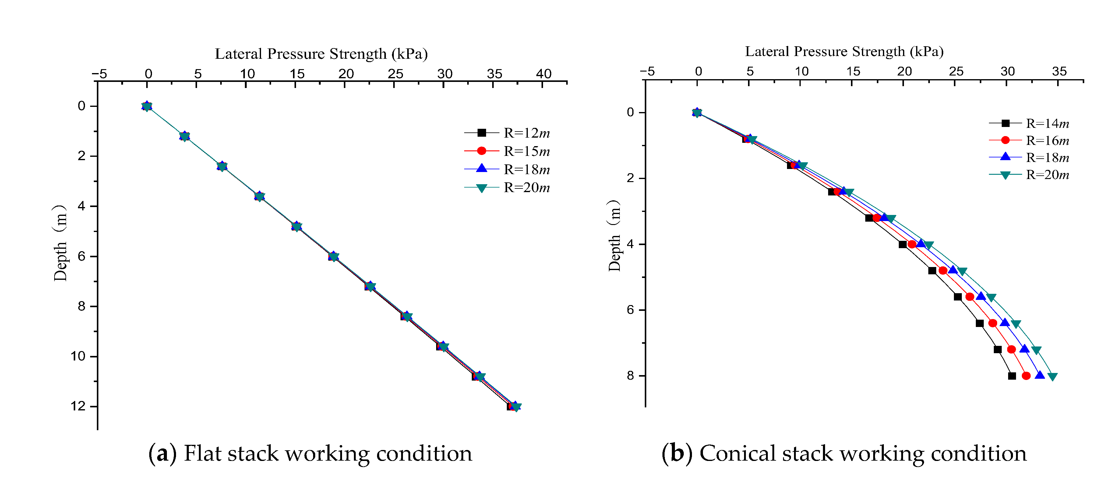
4.2.2. Effect of Silo Radius on Silo Lateral Pressure during an Earthquake

For the flat stack condition, h = 12 m, and the radius R took values of 12 m, 15 m, 18 m, and 20 m in the range of the height diameter ratio of the squat silo. For the conical stack condition, h = 8 m, and the radius R took values of 14 m, 16 m, 18 m, and 20 m. Without considering the material cohesion, the other values were taken as above, and the corresponding silo side pressure strength distribution curves were plotted, as shown in Figure 13.
As can be seen from Figure 13, the silo side pressure strength changed little with the radius increase for the squat silo with a large diameter in flat stack condition, so a silo with a small height diameter ratio can be simplified as a linear retaining wall for calculation. In the conical stack condition, the silo side pressure strength increased with the radius increase; the results corresponded to a radius of 14 m, 16 m, 18 m, and 20 m when at h = 8 m, are separate, 30.5483 kPa, 31.9536 kPa 33.2719 kPa, and 34.5004 kPa showing that the closer to the silo bottom, the larger the difference of side pressure strength.

4.2.3. Effect of the External Friction Angle on the Silo Lateral Pressure during an Earthquake

The external friction angle is generally taken within 22~30°, so in this paper, it was taken as 0°, 22°, 25° and 28° for the flat stack and conical stack conditions to calculate the silo side pressure strength, as shown in Figure 14, without considering the material cohesion and the other values were in Table 5.
As can be seen from Figure 14, the lateral pressure strengths were 43.0316 kPa, 36.9658 kPa, 36.6719 kPa, and 36.3688 kPa when h = 12 m in the flat stack condition and 36.5802 kPa, 31.2003 kPa, 30.6655 kPa, and 30.1547 kPa when h = 8 m in the conical stack condition, corresponding to external friction angles of 0°, 22°, 25° and 28°. The results were larger when the friction force was not considered and decreased as the external friction angle increased for these two conditions, but it changed little when the silo wall friction angle was within the range of given values, which means that the friction must be taken into account in seismic design and the specific external friction angle only needs to be within the corresponding range.

5. Discussion

In response to the problem that the existing research and silo specifications do not give exact theoretical formulae for calculating the seismic lateral pressure of squat silos, this paper directly derived a new formula based on a simplified method using the pseudo-static method and the rotating seismic angle method. The example analysis initially verified the superiority of the new formula in performing static calculations, and the numerical simulations further verified its validity during an earthquake. In addition, the parameters analysis study determined three key parameters involved in the new formula but not fully considered in the other literature, providing a reference basis for seismic silo design, including how to calculate the silo seismic side pressure, how to consider the radius of the squat silo, whether it can be simplified as a linear retaining wall for calculation, and how to take values of the corresponding parameters.
This paper regarded the silo as a curved retaining wall to derive the calculation formula of the seismic lateral pressure on a squat silo. Most of the methods used to study side pressure in curved retaining walls are based on Coulomb theory and use sliding wedge models, as in the Figure 15 [13,14]:
However, these models usually do not take the normal forces N on both sides of the wedge unit into account, and these analysis methods are for cohesionless storage material and static pressure. The study of seismic earth pressure on linear retaining walls is more mature, represented by the pseudo-static method, which is an extension of Coulomb theory under static conditions and reduces the seismic forces to inertia forces acting on the model by the rotating seismic angle method, thus simplifying the dynamic problem to a static one, and finally obtaining the calculation formula under earthquake action. M-O theory [7] (Figure 16) leads to
E a = 1 2 γ H 2 1 k v cos 2 ( φ η α ) cos η cos 2 ( α + η ) cos ( α + φ w + η ) × 1 [ 1 + sin ( φ + φ w ) sin ( φ β η ) cos ( α β ) cos ( α + φ w + η ) ] 2
In fact, the M-O method ignores the interaction forces between the wall and soil and assumes that the fill soil behind the wall is cohesionless, which has limitations in engineering applications. In addition, M-O theory still considers the side pressure strength as a linear distribution, which is not in line with reality. In comparison, the current study extended the application to cohesive soil conditions and the calculation of seismic side pressure in curved retaining walls.
Meanwhile, for the feasibility of formula derivation and practical applications, some prerequisite assumptions were made in this study, such as the hypothesis of a planar sliding surface, the assumption that the silo material has a full load, and the simplification of the horizontal seismic force as a horizontal body force. Furthermore, based on the equivalent seismic loads of the pseudo-static method for practical applications, this study did not involve an in-depth analysis of the true dynamic response to earthquake forces and also did not consider the shear force transfer through squat walls. In practice, however, the rupture surface is usually a curved surface, and the storage material will appear to be flowing as the seismic acceleration increases, which means there are limitations for engineering applications based on this research.
In summary, the seismic lateral pressure studied in this paper was, in fact, the equivalent of changing a dynamic problem to a static problem by means of the pseudo-static method. This study can be applied to the direct calculation of seismic lateral pressure in squat silos and curved retaining walls without considering other dynamic responses of seismic forces when subjected to low seismic forces. Therefore, improvements can be made in the prerequisite assumptions mentioned above, and the dynamic response under real earthquake loads can be studied in depth in the future, including the reloading stiffness, unloading stiffness, stiffness degradation criteria, strain rate effect, etc. In addition, as in previous studies [24,25,26], the seismic performance of the silo wall material, i.e., the shear force, the crack pattern, and the deformed modes of concrete walls, can be further investigated so as to maximize the sustainability of the silo structure.

6. Conclusions

In this paper, we derived a new formula for seismic lateral pressure of the squat silo by introducing the pseudo-static method and rotating seismic angle method, and we verified the formula through numerical simulation and parametric analysis. It can be applied to directly calculate the silo seismic side pressure when in low seismic forces, and it fills the calculation gap of the silo seismic lateral pressure in the silo code. The conclusions can be drawn as follows.
(1)
Silo material cohesion has little impact on the squat silo seismic side pressure and can be ignored; The silo lateral pressure varies by about 10% in the bottom of the squat silo whether considering the friction or not, but its effects can be controlled within a 2% variation by simply selecting the friction angle within a reasonable range according to the silo code.
(2)
When in the flat stack condition, the large-diameter squat silo can be simplified as a linear retaining wall as the impact of the radius variation on the seismic lateral pressure is less than 1%; When in the conical stack condition, the silo lateral pressure increases by about 5% with the radius increase and can be calculated using the proposed new formula. In general, the proposed new formula fitted well with the numerical simulation in the flat stack case and also had a degree of superiority in the conical stack case.
(2)
The formula derivation was based on Coulomb theory and assumed that the silo material was in full load, as well as simplifying the horizontal seismic force as the horizontal body force, transverse force perpendicular to the silo center line, which means the study can only be applied to the direct calculation of seismic lateral pressure in squat silos when subjected to low seismic forces, and also indicates a study direction for the future.

Author Contributions

Conceptualization, G.Z.; Supervision, G.Z.; funding acquisition, G.Z.; Data curation, R.Z.; Writing—original draft, R.Z.; Writing—review & editing, R.Z.; visualization, R.Z. All authors have read and agreed to the published version of the manuscript.

Funding

This research was funded by the National Natural Science Foundation of China, grant number “51978668”.

Institutional Review Board Statement

Not applicable.

Informed Consent Statement

Not applicable.

Data Availability Statement

Data is contained within the article.

Acknowledgments

We would like to acknowledge the helpful comments on this paper received from our reviewers.

Conflicts of Interest

The authors have no financial or proprietary interest in any material discussed in this article.

Nomenclature

βInclination angle of the silo material
θRupture angle
ηSeismic angle
CCohesion in surface ABCD
CwCohesion in rupture surface CDJK
NNormal force
FRReaction force on the rupture surface
FhVolume force in the horizontal direction
FvVolume force in the vertical direction
RRadius of the squat silo
WGravity of the sliding wedge
φInternal friction angle
φwExternal friction angle
khSeismic acceleration coefficient in the horizontal direction
kvSeismic acceleration coefficient in the vertical direction
VVolume of the sliding wedge
hHeight of the squat silo
ρDensity
μPoisson’s ratio
γBulk density of the silo material
cCohesion of the silo material
KaLateral pressure coefficient of the squat silo

References

  1. Reimbert, M.; Reimbert, A. Silos theory and practice. J. Thought 1976, 5, 141–156. [Google Scholar]
  2. Janssen, H.A. Versuche über Getreidedruck in Silozellen. Zeitschr. Ver. Dtsch. Ing. 1895, 39, 1045–1049. [Google Scholar]
  3. Airy, W. The Pressure of Grain. (Including Appendixes). Minutes Proc. 1897, 131, 347–358. [Google Scholar] [CrossRef] [Green Version]
  4. Younan, A.H.; Veletsos, A.S. Dynamics of solid-containing tanks. I: Rigid tanks. J. Struct. Eng. 1998, 12, 52–61. [Google Scholar] [CrossRef]
  5. Veletsos, A.S.; Younan, A.H. Dynamics of solid-containing tanks. II: Flexible tanks. J. Struct. Eng. 1998, 124, 62–70. [Google Scholar] [CrossRef]
  6. Zhao, S.; Liao, H. Soil Mechanics, 2nd ed.; Higher Education Press: Beijing, China, 2010. [Google Scholar]
  7. Mylonakis, G.; Kloukinas, P.; Papantonopoulos, C. An alternative to the Mononobe–Okabe equations for seismic earth pressures. Soil Dyn. Earthq. Eng. 2007, 27, 957–969. [Google Scholar] [CrossRef]
  8. Silvestri, S.; Gasparini, G.; Trombetti, T.; Foti, D. On the evaluation of the horizontal forces produced by grain-like material inside silos during earthquakes. Bull. Earthq. Eng. 2012, 10, 1535–1560. [Google Scholar] [CrossRef]
  9. Yu, X.; Raeesi, A.; Ghaednia, H.; Heydariha, J.; Das, S.; Xie, S. Behavior of a large steel field silo structure subject to grain loading. J. Perform. Constr. Facil. 2017, 31, 04017038. [Google Scholar] [CrossRef]
  10. Tang, J.; Lu, H.; Guo, X.; Liu, H. Static wall pressure distribution characteristics in horizontal silos. Powder Technol. 2021, 393, 342–348. [Google Scholar] [CrossRef]
  11. Jing, H.; Wang, X.; Yang, J.; Chen, H. Static and seismic pressure of cylindrical steel silo model with granular materials. J. Constr. Steel Res. 2022, 198, 107515. [Google Scholar] [CrossRef]
  12. Xu, Z.; Liang, P. Modified lateral pressure formula of shallow and circular silo considering the elasticities of silo wall and storage materials. Sci. Rep. 2022, 12, 7069. [Google Scholar] [CrossRef] [PubMed]
  13. Shi, W.; Zhu, B. The experimental study of earthquake response of reinforced concrete cylinder silos. Spec. Struct. 1994, 4, 55–58. [Google Scholar]
  14. Yuan, F.; Wang, F.; Xiao, Z. Analysis on active bulk-solid pressures on curvy walls and its application. J. Rock Mech. Eng. 2004, 6, 3900–3904. [Google Scholar]
  15. Jing, H.; Chen, H.; Yang, J.; Li, P. Shaking table tests on a small-scale steel cylindrical silo model in different filling conditions. In Structures; Elsevier: Amsterdam, The Netherlands, 2022; Volume 37, pp. 698–708. [Google Scholar]
  16. Gandia, R.M.; Gomes, F.C.; De Paula, W.C.; Rodriguez, P.J.A. Evaluation of pressures in slender silos varying hopper angle and silo slenderness. Powder Technol. 2021, 394, 478–495. [Google Scholar] [CrossRef]
  17. Livaoglu, R.; Durmuş, A. A simplified approximation for seismic analysis of silo-bulk material system. Bull. Earthq. Eng. 2016, 14, 863–887. [Google Scholar] [CrossRef]
  18. Zhang, L. Simulation of Seismic Shaking Table Experiments on the Structural Model of Silo-Bearing Vertical Silo. Master’s Thesis, Henan University of Technology, Zhengzhou, China, 2010. [Google Scholar]
  19. Djelloul, Z.; Mohammed, D. Contribution to the seismic behaviour of steel silos: Full finite-element analysis versus the Eurocode approach. Asian J. Civil Eng. 2018, 19, 757–773. [Google Scholar] [CrossRef]
  20. Ji, S.; Wang, S.; Peng, Z. Influence of external pressure on granular flow in a cylindrical silo based on discrete element method. Powder Technol. 2019, 356, 702–714. [Google Scholar] [CrossRef]
  21. Temsah, Y.; Jahami, A.; Aouad, C. Silos structural response to blast loading. Eng. Struct. 2021, 243, 112671. [Google Scholar] [CrossRef]
  22. Sun, W.; Feng, J.; Mao, F.; Wang, C. Experiment and simulation analysis of loading and unloading of shallow round bins in aboveground conveying channels. J. Northeast. Univ. 2021, 42, 879–885+892. [Google Scholar]
  23. Jing, X.; Wang, X.; Chen, H. Simulation of grain storage side pressure in steel silo based on Duncan-Zhang model. Comput. Simul. 2022, 39, 259–263+505. [Google Scholar]
  24. Faraone, G.; Hutchinson, T.C.; Piccinin, R.; Silva, J.F. Seismic Performance of Varying Aspect Ratio Full-Scale Concrete Walls. ACI Struct. J. 2022, 119, 19–34. [Google Scholar]
  25. Faraone, G.; Hutchinson, T.C.; Piccinin, R.; Silva, J.F. Numerical response prediction of full-scale concrete walls subjected to simulated in-plane seismic loading. Eng. Struct. 2022, 264, 114405. [Google Scholar] [CrossRef]
  26. Almasabha, G.; Chao, S.H. A New Reinforcing Configuration for Achieving High-Ductility and High-Strength Rectangular Squat Structural Walls. ACI Struct. J. 2023, 120, 253–268. [Google Scholar]
  27. GB50077-2017; Design Standard for Reinforced Concrete Silos. China Planning Press: Beijing, China, 2017.
  28. ACI 313-97; Standard Practice for Design and Construction of Concrete Silos and Stacking Tubes for Storing Granular Materials. American Concrete Institute: Farmington, MI, USA, 1998.
  29. BS EN1991-4:2006; Eurocode 1-Actions on Structures-Part 4: Silos and Tanks. European Commission: Brussels, Belgium, 2013.
  30. Rotter, J.M.; Hull, T.S. Wall loads in squat steel silos during earthquakes. Eng. Struct. 1989, 11, 139–147. [Google Scholar] [CrossRef]
  31. Yuan, F. Analysis and Engineering Applications of Bulk Pressure on the Inside of Curved Retaining Walls. Ph.D. Thesis, Dalian University of Technology, Dalian, China, 2004. [Google Scholar]
Figure 1. The method flow chart.
Sustainability 15 05098 g001
Figure 2. The free-body diagram of the calculation model.
Sustainability 15 05098 g002
Figure 3. The diagram and force analysis in the conical stack condition.
Sustainability 15 05098 g003
Figure 4. Comparison of silo lateral pressure strength in the flat stack condition.
Sustainability 15 05098 g004
Figure 5. Comparison of silo lateral pressure strength in the conical stack condition.
Sustainability 15 05098 g005
Figure 6. The simulation model is in the flat stack condition.
Sustainability 15 05098 g006
Figure 7. The deformed shape of the modes in the flat stack condition.
Sustainability 15 05098 g007
Figure 8. The lateral pressure strength distribution diagram in the flat stack condition.
Sustainability 15 05098 g008
Figure 9. The simulation model is in the conical stack condition.
Sustainability 15 05098 g009
Figure 10. The deformed shape of the modes in the conical stack condition.
Sustainability 15 05098 g010
Figure 11. The lateral pressure strength distribution diagram in the conical stack condition.
Sustainability 15 05098 g011
Figure 12. The lateral pressure strength distribution diagram with different cohesion values.
Sustainability 15 05098 g012
Figure 13. The lateral pressure strength distribution diagram with different radii.
Sustainability 15 05098 g013
Figure 14. The lateral pressure strength distribution diagram with different external friction angles.
Sustainability 15 05098 g014
Figure 15. The planar force diagram of the sliding wedge in references (a) [13]; (b) [14].
Sustainability 15 05098 g015
Figure 16. The calculation models in M-O theory. (a) Schematic diagram of M-O theory; (b) Planar model after rotating the seismic angle.
Sustainability 15 05098 g016
Table 1. The lateral pressure strength was measured as theoretical data.
NumberDepth (m)Measured Data [31] (kPa)New Formula (kPa)Coulomb Formula (kPa)Silo Code [27] (kPa)
12.87.387.327.757.18
24.812.5312.6213.4812.31
36.318.8116.6317.6116.16
47.820.8220.6821.8620.01
59.324.6924.7526.0923.85
610.928.9229.1430.3927.96
712.432.6133.2934.6431.80
813.435.9736.0737.3834.37
Table 2. The lateral pressure strength was measured, and theoretical data.
NumberDepth (m)Measured Data [31] (kPa)New Formula (kPa)Coulomb Formula (kPa)Silo Code [27] (kPa)
10.536.412.352.591.93
22.0511.418.6510.047.46
33.5614.5914.2717.4312.95
45.1017.1719.4424.9718.55
56.6220.7923.8232.4224.08
67.6024.1626.4137.2227.64
Table 3. The silo wall material parameter values.
Elastic Modulus (GPa)μρ (kg/m3)φ (°)φw (°)Friction Coefficient
300.227002521.80.4
Table 4. The silo storage material parameter values.
Elastic Modulus (GPa)μρ (kg/m3)c (kPa) in Flat Stackc (kPa) in Conical Stack
200.37880 or 10 or 2
Note: The (0 or 1) represents the different values when considering cohesion or not, and (0 or 2) is the same.
Table 5. The parameter values involved in the calculation.
R (m)h (m)khβ (°)
In flat stack working condition15120.1/
In conical stack working condition1580.125
Disclaimer/Publisher’s Note: The statements, opinions and data contained in all publications are solely those of the individual author(s) and contributor(s) and not of MDPI and/or the editor(s). MDPI and/or the editor(s) disclaim responsibility for any injury to people or property resulting from any ideas, methods, instructions or products referred to in the content.

