Article

Study on Mine Earthquakes Mechanism and Ground Vertical Well Hydraulic Fracturing Shock Absorption in Thick Hard Rock Mine

1
Key Laboratory of Ministry of Education for Efficient Mining and Safety of Metal Mines, School of Civil and Resource Engineering, University of Science and Technology Beijing, Beijing 100083, China
2
Shandong Energy Group Company Limited, Jinan 250014, China
3
Hebei State Key Laboratory of Mine Disaster Prevention, North China Institute of Science and Technology, Langfang 065201, China
4
Beijing Anke Xingye Science and Technology Co., Ltd., Beijing 102299, China
*
Author to whom correspondence should be addressed.
Sustainability 2023, 15(6), 5122; https://doi.org/10.3390/su15065122
Submission received: 28 October 2022 / Revised: 8 March 2023 / Accepted: 10 March 2023 / Published: 14 March 2023
(This article belongs to the Special Issue Deep Mining Engineering in Sustainability)

Abstract

:
Mine earthquakes are serious disasters in coal mines, especially in extremely thick hard strata. This study investigates the occurrence mechanism of fracture-type mine earthquakes in thick hard strata. Hydraulic fracturing by ground vertical well was used for shock absorption. Dongtan coal mine was taken as a case study. Field investigation, theoretical analysis, industrial tests, and field monitoring were used for revealing the mechanism. First, the mechanical model of extremely thick, hard strata under horizontal concentrated stress was established. The fracture step equation and energy release equation of extremely thick hard rock were derived by semi-inverse solution and variational method. Then, the mechanical model of extremely thick hard rock after hydraulic fracturing by ground vertical well was established. The relationship between the spacing of the ground vertical well and the maximum magnitude of mine earthquakes was deduced. The fracturing well in the 6306 working face was designed for controlling the maximum mine earthquake magnitude. Results show that the increases in the breaking distance of the thick hard rock layer led to an increase in the released energy during the fracture, and an enhancement of the magnitude of the mine earthquake. By applying hydraulic fracturing technology using the ground vertical shaft, the occurrence frequency and total energy of mine earthquakes above 1.5 ML in the 6306 working face decreased by 54.55% and 81.22% than that in 6304 working face, and reduced by 70% and 84.98% than that in 6305 working face. Hydraulic fracturing technology by ground vertical well can significantly reduce the frequency of fracture-type and the total energy of mine earthquakes in extremely thick and hard strata. However, it can not prevent and control the occurrence of back-transition mine earthquakes and slip-type mine earthquakes. The obtained results can provide a basis for the fracture-type mine earthquake mechanism and fracturing shock absorption technology in coal mines with super-thick hard strata.

1. Introduction

The exploitation of mineral resources has a dual role in sustainable development. On the one hand, mineral resources can provide material security for sustainable economic development; on the other hand, mineral resources are non-renewable resources, and mining activities are very destructive to the ecological environment. With the continuous reduction of shallow coal seam resources, a large number of mines are gradually mining from shallow to deep. In deep mining, the rock mass is strongly disturbed by mining activities while bearing high ground stress. The earthquakes induced by mining activities are called mine earthquakes [1,2,3,4].
In China’s major coal-producing provinces and regions, there is very thick hard rock in the mines. Because the hard rock group has the characteristics of high strength, large thickness, strong integrity, and a tendency to not fall naturally, it can easily accumulate a lot of elastic energy, and mine earthquakes are easily induced when the thick hard rock layer breaks. Therefore, to ensure safe and efficient mining of coal in China it is imperative that reliable mine earthquake mechanism and shock absorption research in extremely thick hard rock mine is carried out.
At present, scholars in China and worldwide have carried out the following related research on the mechanisms and prevention of mine earthquakes. For example, Dou et al. [5] divided coal mine earthquakes into three types: mining-induced rupture type, extremely thick overburden type, and high-energy mine earthquake type. By analyzing the influencing factors of mine earthquake vibration waves, it was revealed that the peak velocity and energy of vibration waves have a negative exponential relationship with the propagation distance. Jiang et al. [6] deduced the calculation method of thick and hard key strata fracture by theoretical analysis. By studying the mechanism of roadway instability caused by the fracture of thick and hard roof, Ning [7] proposed the use of deep hole blasting technology to pre-split hard roof. Yang et al. [8] thought that under the effect of mining disturbance, mine earthquakes are likely to happen along the empty working face. Li et al. [9] used mathematical models to analyze the static stress distribution of hard roof and evaluated mine earthquakes by CT scanning technology. Urbancic et al. [10] evaluated the fracture and stress conditions associated with deep ore mining using microseismic monitoring techniques. Driad-Lebeau et al. [11] considered that high level stress is the main cause of mine earthquakes. Zhu et al. [12] put forward the calculation model of advance abutment stress based on the analysis of load transfer mechanism of key strata and super-thick topsoil and ascertained that the higher advance abutment pressure was the main reason for frequent mine earthquakes near the working face. Zhang et al. [13] believed that ultra-high water backfilling goaf can alleviate the risk of mine earthquakes. Wu et al. [14] studied the process of mine earthquake occurrence by microseismic monitoring. Yu et al. [15] established the mechanical model of caving roof based on damage mechanics and statistical strength theory. Lv et al. [16] studied the mechanism of fault-induced mine earthquakes by theoretical analysis and microseismic monitoring. Rong et al. [17] made a distinction between typical mine earthquakes and atypical mine earthquakes and analyzed the energy characteristics of mine earthquakes through a coal-rock dynamic system model. Dong et al. [18] proposed a prediction model based on theoretical analysis and mathematical processing to solve the problems of accurate prediction and early warning of compound dynamic disasters. Guo et al. [19] suggested that when there was a thick and hard roof, roof strata can accumulate higher energy, so the possibility of a mine earthquake was higher. He et al. [20] thought that the inclined, extremely thick coal seam under the condition of goaf filling was prone to rockburst. They proved that roof fracture was the main cause of rockburst by establishing the mechanical model of steeply inclined suspended roof structure. Lv et al. [21] discussed the disaster mechanism of rockburst under dynamic and static loads from the aspects of blasting tendency and the time failure mode of coal specimens. Zhou et al. [22] studied the mechanism and control method of structural rockburst in hard rock tunnel. Sainoki et al. [23] thought that the fault slip-type mine earthquake would cause serious damage to the mine wellhead and studied its mechanism through the concave convex model. Jiang et al. [24] studied the correlation between hard roof and mine earthquakes through a similar material simulation test. Yang et al. [25] used the thin plate theory to study the limit caving step of thick hard rock strata and studied the occurrence law of mine earthquakes. Cai et al. [26] suggested that the existence of faults is the main cause of mine earthquakes. Prusek et al. [27] studied mine earthquakes in coal mines, and predicted the possibility of dynamic load on road damage by numerical simulation. Carpinteri et al. [28] suggested that mine earthquakes are related to the moon phase. Brace et al. [29] used the discrete element method to verify the stick-slip instability theory of mine earthquakes.
Furthermore, in recent years, hydraulic fracturing technology has been vigorously developed in industrial applications [30,31,32,33]. Regarding the prevention and control of mine earthquakes by hydraulic fracturing of hard roof, Zhu et al. [34] considered that hydraulic fracturing of coal seam was an effective method to prevent rockburst before coal seam mining and evaluated the degree of hydraulic fracturing by microseismic monitoring. Dang et al. [35] demonstrated the possibility of applying hydraulic fracturing technology in the field of coal mining and counted and analyzed the cases of using hydraulic fracturing technology to prevent and control mine earthquakes. Ma et al. [36] considered that gas fracturing overcomes the limitations of hydraulic fracturing. They studied the mechanical principle of gas fracturing by using the damage-based heat flow mechanics coupling model. Figueiredo et al. [37] studied the hydraulic fracturing process in complex geological environments. Ge et al. [38] proposed a new type of hydraulic fracturing sealing material composed of cement, early strength water reducing agent, and polypropylene fiber to solve the problems of shrinkage, poor sealing effect, high cost and improper sealing length of hydraulic fracturing borehole sealing material in underground coal mines. Lu et al. [39] considered that initial hydraulic pressure and position were important parameters of hydraulic fracturing in coal mines, which are greatly affected by ground stress and coal seam occurrence. Lin et al. [40] considered that the geometric shape of hydraulic fracturing cracks is crucial in improving the fracturing effect in the control of hard roof in coal mines. They proved through experiments that the complexity of the near wellbore usually leads to a smaller lateral crack size. Xu et al. [41] simulated the relationship between hydraulic pressure and fracture morphology by PFC.
The above research results are of great significance for understanding the fracture-type mine earthquakes in extremely thick hard rock strata and the ground hydraulic fracturing shock absorption technology. However, there are few studies on the mechanism of mine earthquakes in extremely thick hard rock strata and the mechanism of preventing and controlling mine earthquakes in extremely thick hard rock strata by hydraulic fracturing in vertical wells.
The purpose of this paper is to study the mechanism of mine shock and the damping technology of fracturing in thick and hard strata. In this paper, the mechanical model of clamped beam and cantilever beam under horizontal concentrated stress is established, and the fracture step equation and energy release equation of extremely thick hard rock stratum are derived by semi-inverse solution and variational method. By establishing the mechanical model of simply supported beam after ground vertical well hydraulic fracturing in super-thick hard rock, the relationship between ground vertical well spacing and maximum mine earthquake magnitude is deduced, and the design of fracturing well spacing based on controlling the maximum earthquake magnitude in the 6306 working face is completed.

2. Overview of the Sixth Mining Area of Dongtan Coal Mine and Its Mine Earthquakes Occurrence

2.1. Stratum Structure of the Sixth Mining Area in Dongtan Coal Mine

The sixth mining area is a North China type Carboniferous Permian fully concealed coalfield. The strata are briefly described from top to bottom as follows: the thickness of Quaternary topsoil is 79.15–141.18 m, with an average of 121.98 m; the Jurassic lithology is mainly composed of gray-green siltstone, fine sandstone, mudstone, and fine sandstone, with a thickness of 393.27–735.20 m and an average of 500.56 m. The Permian lithology is dominated by mudstone, fine sandstone, medium sandstone, coarse sandstone, siltstone, 2 coal and 3 coal, with a thickness of 0–383.23 m and an average of 191.61 m. The location map of the sixth mining area is shown in Figure 1.

2.2. Mining Situation in the Working Face of the Sixth Mining Area

The mining sequence of the sixth mining area is 6304-6305-6303-6306 working face, and the 6306 working face is currently being mined, as shown in Figure 2. Table 1 shows the stratum structure exposed by the O2-D7 borehole in the sixth mining area. The buried depth of coal seam is 675.85 m. According to the O2-D7 borehole, the stratum is divided into three key strata groups. The third key strata group is 189.2 m thick and 361 m away from the coal seam. The second key stratum group is 263.4 m thick and 86 m away from the coal seam. The first key stratum group is 29 m thick and 12.4 m away from the coal seam.

2.3. Occurrence Law of Mine Earthquakes in Sixth Mining Area of Dongtan Coal Mine

During the production process of the 6304 working face, a total of 4926 microseismic events were monitored. Among them, there were 4437 events where the vertical distance between the source and the coal seam was greater than 86 m, which accounted for 90.07% of the total number of microseismic events. There were 204 events where the vertical distance between the source and the coal seam was greater than 361 m, which accounted for 4.14% of the total number of microseismic events. There were 237 microseismic events with magnitude greater than 1.5 ML; in 221 of these, the vertical distance between the source and the coal seam was greater than 86 m, accounting for 93.25%. There were 81 microseismic events with magnitude greater than 1.8 ML; in 76 of these, the vertical distance between the source and the coal seam was greater than 86 m, accounting for 93.83%. There were 34 microseismic events with a magnitude greater than 2.0 ML, in 33 of these, the vertical distance between the source and the coal seam was greater than 86 m, accounting for 97.06%.
It can be seen from the results of microseismic monitoring in the stoping process of the 6304 working face that 90.07% of mine earthquakes occurred in super-thick hard rock strata, and 93.25%, 93.83%, and 97.06% of mine earthquakes with magnitude greater than 1.5 ML, 1.8 ML, and 2.0ML occurred in super-thick hard rock strata, respectively. The maximum magnitude was 2.71 ML, the location was 176.91 m above the 6304 goaf, and the average footage was 455 m.
During the production process of the 6305 working face, a total of 5129 microseismic events were monitored. Among them, there were 3835 events in which the vertical distance between the source and the coal seam was greater than 86 m, accounting for 74.77% of the total number of microseismic events. There were six events in which the vertical distance between the source and the coal seam was greater than 361 m, accounting for 0.12% of the total number of microseismic events. There were 309 microseismic events with magnitude greater than 1.5 ML, of which 199 had a vertical distance between the source and the coal seam greater than 86 m, accounting for 64.40%. There were 142 microseismic events with magnitude greater than 1.8 ML, among which 96 had a vertical distance between source and coal seam greater than 86 m, accounting for 67.61%. There were 56 microseismic events with magnitude greater than 2.0 ML, of which 40 had a vertical distance of more than 86 m from the source to the coal seam, accounting for 71.43%.
It can be seen from the results of microseismic monitoring in the mining process of the 6305 working face that 74.77% of the mine earthquakes occurred in super-thick hard rock strata, and 64.40%, 67.61%, and 71.43% of the mine earthquakes with magnitude greater than 1.5 ML, 1.8 ML, and 2.0 ML, respectively, occurred in super-thick hard rock strata. The maximum magnitude was 2.82 ML, the location was 186 m above the 6305 goaf, and the average footage was 673 m.
According to the key strata, the fracture-type mine earthquakes are divided into low mine earthquakes and high mine earthquakes, as shown in Figure 3. Based on the occurrence law of mine earthquakes in the 6304 and 6305 working faces, according to the literature [5], mine earthquakes greater than 104 J are high-energy mine earthquakes. The fracture-type mine earthquakes in the thick and hard rock strata of the sixth mining area of Dongtan coal mine are divided into four categories: low-level low-energy mine earthquakes, low-level high-energy mine earthquakes, high-level low-energy mine earthquakes, and high-level high-energy mine earthquakes. Among the four types of mine earthquakes, high-position low-energy mine earthquakes and high-position high-energy mine earthquakes account for 82.42% of the total number of mine earthquakes. It can be seen that the occurrence of extremely thick hard rock strata is the main cause of mine earthquakes in the sixth mining area of Dongtan coal mine.

3. Study on Fracture-Type Mine Earthquake Mechanism of Super-Thick Hard Rock

Through the above analysis, it is found that the source of high-energy mine earthquakes in Dongtan coal mine are mainly located in the super-thick high key strata, and the movement of super-thick hard rock strata is the main reason for the occurrence of high-energy mine earthquakes in Dongtan coal mine. In the early stage of coal seam mining, the thick hard rock strata can support the rock mass under its own strength to form a large area of ‘rock plate’ or hanging roof structure. With the increase of the mining range, the exposed area of super-thick hard rock strata increases, and separation, bending, and sinking gradually occur. When the ultimate fracture span is reached, the super-thick hard rock strata fracture for the first time. As the coal seam continues to be mined, periodic fractures occur in the extremely thick hard rock strata. Due to the characteristics of large thickness, high strength, and good integrity of thick and hard rock strata, it can easily accumulate a large amount of gravitational potential energy and elastic strain energy. The accumulated gravitational potential energy and elastic energy are released during the movement of thick and hard rock strata, which easily induces high-energy mine earthquakes.

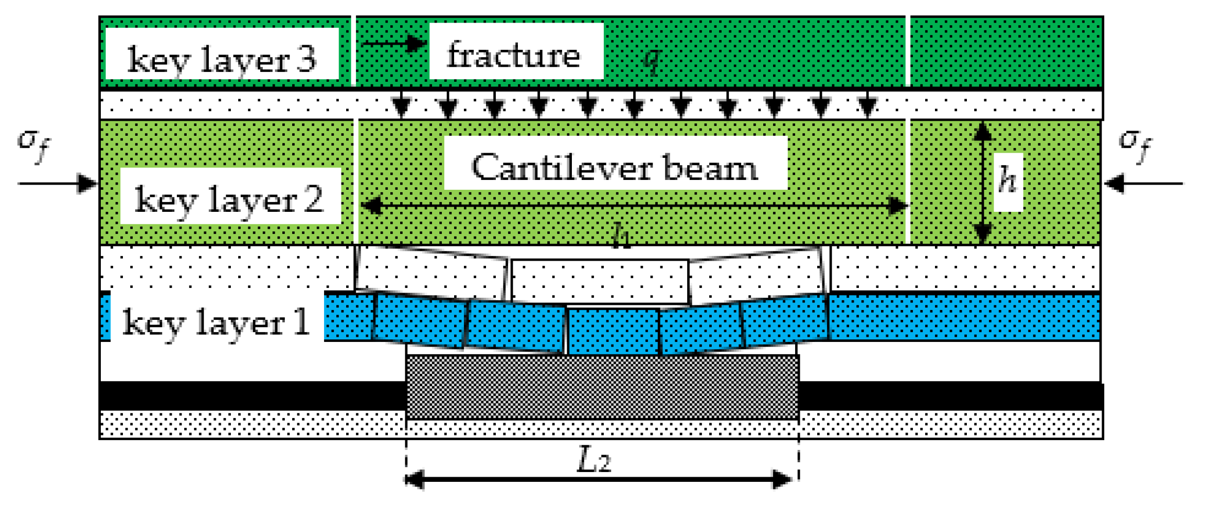
3.1. Mechanics Analysis of Fracture-Type Mine Earthquakes in Super-Thick Hard Rock

The motion state of extremely thick and hard rock strata determines the evolution and distribution of stope stress, and the evolution and final distribution of stress field will also affect the movement of rock strata. The study of key strata theory shows that the movement range of rock strata controlled by thick and hard key strata includes the key strata itself and the load rock strata dominated by overlying soft rock, which is mainly characterized by the movement state of extremely thick hard rock. Coal mining causes the redistribution of original rock stress, and the vertical stress transfers to the periphery of the stope. The influence mainly appears in the roof and floor strata adjacent to the stope. The initial fracture of extremely thick hard rock strata can be simplified as a mechanical model of fixed beam of homogeneous isotropic body, as shown in Figure 4. The periodic fracture of extremely thick hard rock strata can be simplified as a mechanical model of cantilever beam, as shown in Figure 5.

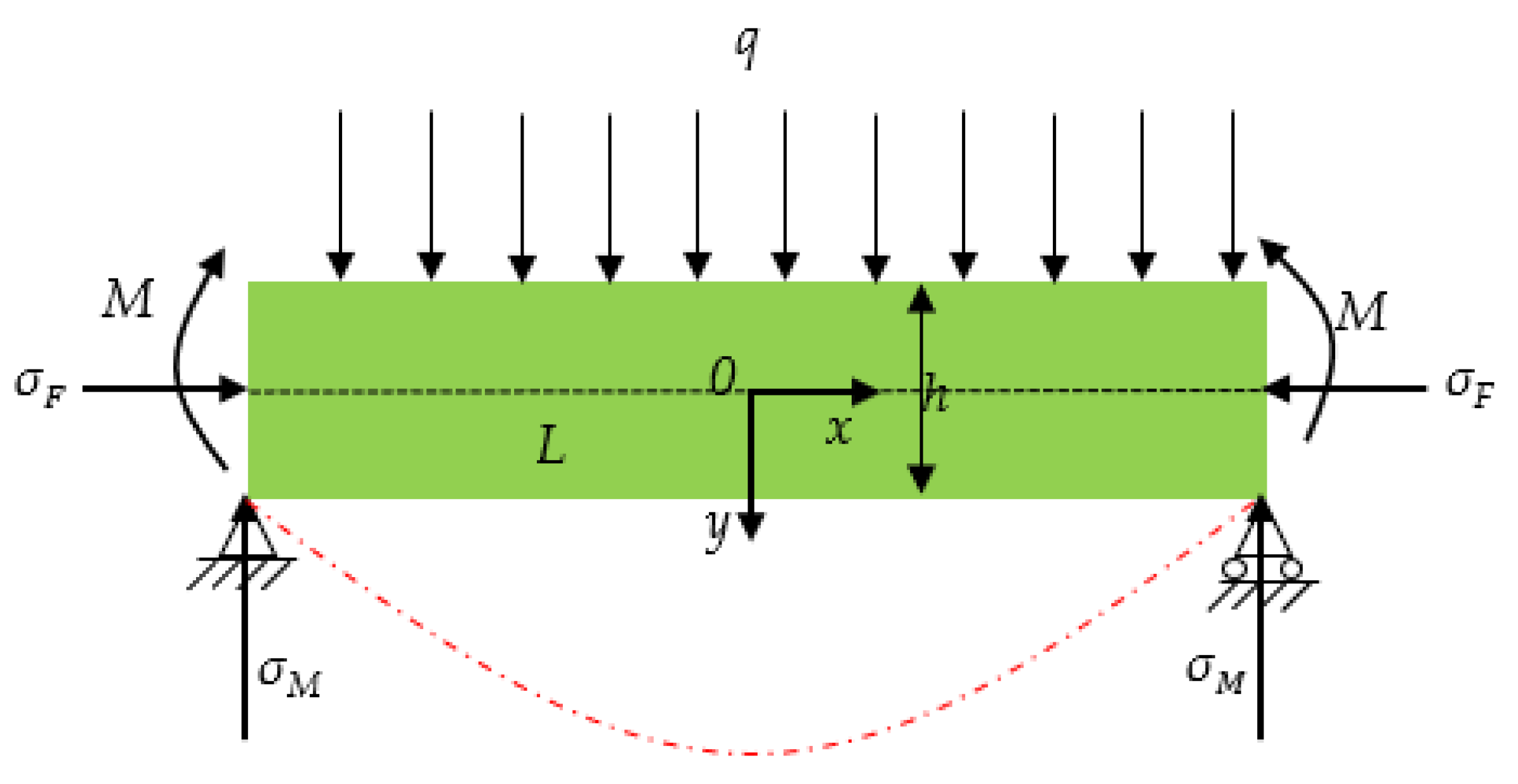
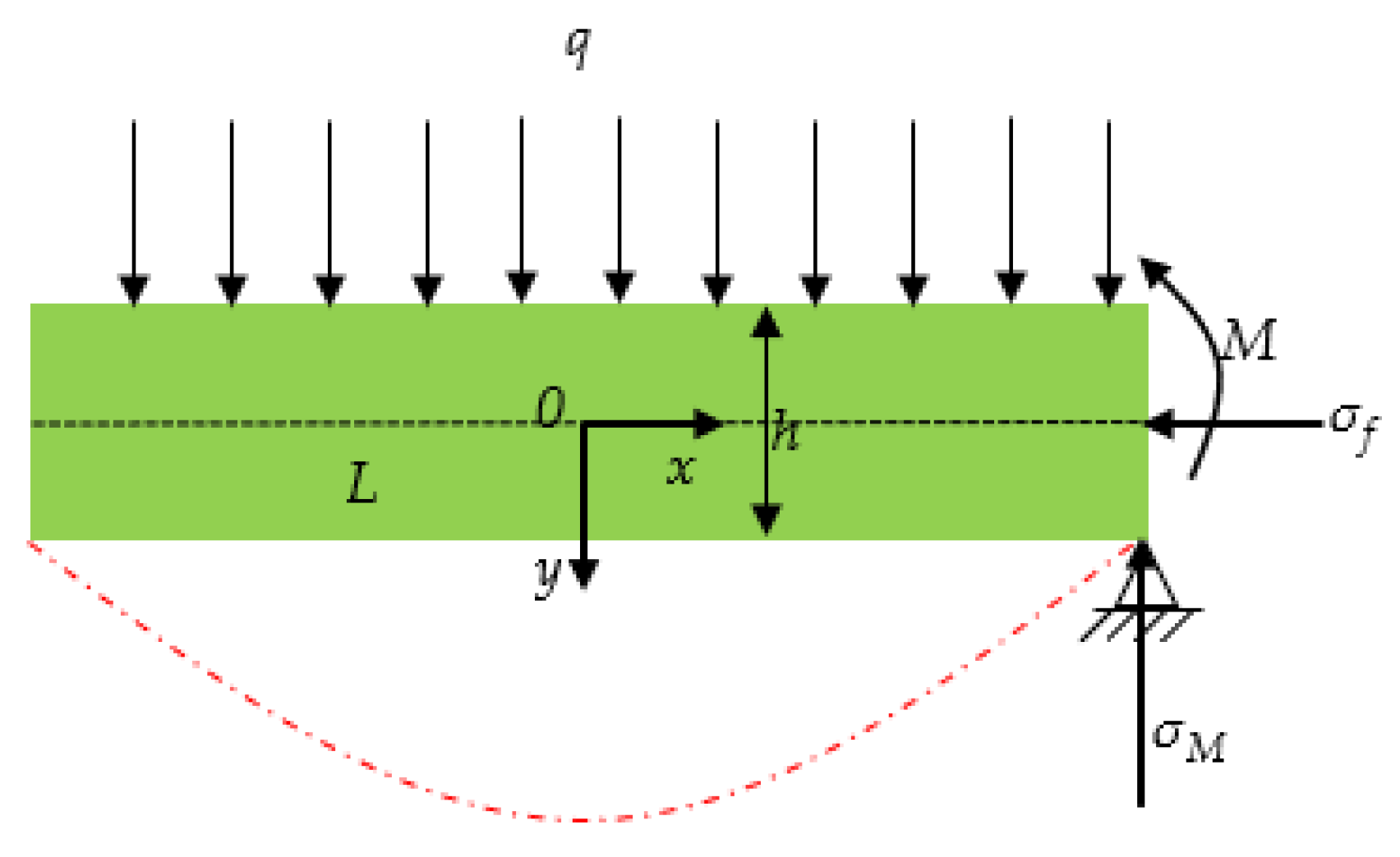
3.1.1. Initial Fracture Mechanics Analysis of Super-Thick Hard Rock

According to Figure 4, the self-weight q of the overlying soft rock layer on the thick and hard rock layer is applied above the thick and hard rock layer in the form of uniform load. In the horizontal direction, the thick and hard rock layer is not only subjected to the original horizontal stress σ f , but also to the horizontal transfer stress σ f ,   caused by mining. A simplified model of primary fracture mechanics for extremely thick hard rock is established with the center of clamped beam as the origin of coordinates, as shown in Figure 6, where σ F is horizontal concentrated stress, h is the thickness of super-thick hard rock, L is the span of super-thick hard rock, σ M is the bearing stress of the fixed end base, and M is the bending moment of the beam.
It is assumed that the action of the cushion layer at the supporting end of the beam is not considered, and the unit width is taken in the direction of the working face. At this time, the mechanical model of the fixed beam at both ends can be regarded as a plane strain problem. The rock layer above the thick and hard rock layer is regarded as a uniform load, and the thick and hard rock is subjected to volume force. According to the semi-inverse solution of elastic mechanics [42], the basic form of the stress component of the rock beam is obtained.
σ x = 6 q h 3 x 2 y + 4 q h 3 y 3 + 6 Oy + 2 P σ y = 2 q h 3 y 3 + 3 q 2 h y q 2 τ xy = 6 q h 3 xy 2 3 q 2 h x
In the equation, O is the dimensionless undetermined coefficient, N/m3; P is the dimensionless undetermined coefficient, N/m2; σ and τ are the tensile (compressive) stress and shear stress corresponding to the rock beam section   q = γ   H i , and H i is the height of overlying soft rock controlled by key stratum i.
On the left and right sides of the beam, due to the existence of horizontal concentrated stress, this requires that when x = ±   l ( L = 2 l ), regardless of the value of y  h 2 y h 2 , there are σ x =   σ F . The polynomial pair σ x is used to solve the problem, that is, the principal vectors synthesized by σ x on the boundary of x = ±   l are σ F . The bedding moment M = q + γ h l 2 3 h 2 h 2 σ F y d y , that is:
h 2 h 2 σ x x = ± l d y = h 2 h 2 σ F d y h 2 h 2 σ x x = ± l y d y = M
According to Equation (2), the expressions of O and P are obtained.
P = F 2 O = q 2 γ h l 2 3 h 3 q 10 h
By substituting Equation (3) into Equation (1), we can obtain Equation (4):
σ x = 6 q h 3 x 2 y + 4 q h 3 y 3 + 2 q 2 γ h l 2 h 3 y 3 q 5 h y σ F σ y = 2 q h 3 y 3 + 3 q 2 h y q 2 τ xy = 6 q h 3 xy 2 3 q 2 h x
σ F = σ f + σ f
According to Zhang Ming’s [43] formula for estimating horizontal concentrated stress.
σ F = λ γ H i 1 + h i 2 H h i H h i
In the equation, λ is the horizontal lateral pressure coefficient; λ = v 1 v , v is the Poisson’s ratio of rock strata; γ is rock bulk density, 0.025 kN/m3; is the horizontal stress transfer coefficient, 0 < φ < 1 ; h i is the distance from key stratum i to coal seam, m; H is buried depth of coal seam, m; and H i is the distance from key layer i to the surface, m.
For the fixed beam, the negative bending moment at the support is the largest, and the upper surface of the fixed end beam (x = ± l, y = − h/2) is first to be broken. Suppose that the three stress components of the fixed beam are σ x 1 , σ y 1 , and τ xy 1 . We put x = ± l, y = − h/2 into Equation (4).
σ x 1 = 2 q + γ h l 2 h 2 q 5 σ F σ y 1 = q τ xy 1 = 0
If the rock stratum does not break, the tensile stress at the upper surface of the embedded end (x = ± l, y = − h/2) should not be greater than the ultimate tensile strength of the rock, that is, σ x 1 σ t , σ t is the ultimate tensile strength of the extremely thick hard rock stratum. The initial fracture span L 0 of the extremely thick hard rock stratum is obtained.
L 0 = 2 l = 2 h 5 σ t + 5 σ F + q 10 q + γ h  

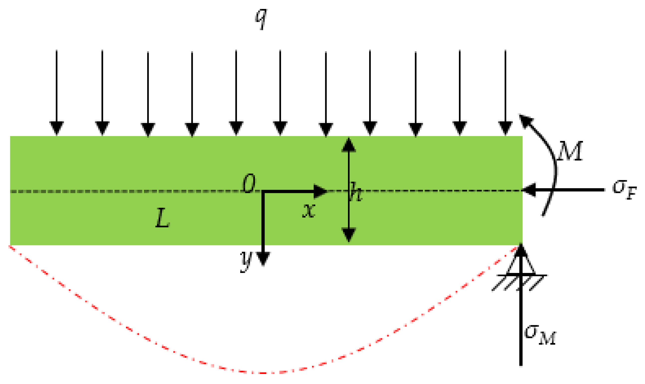
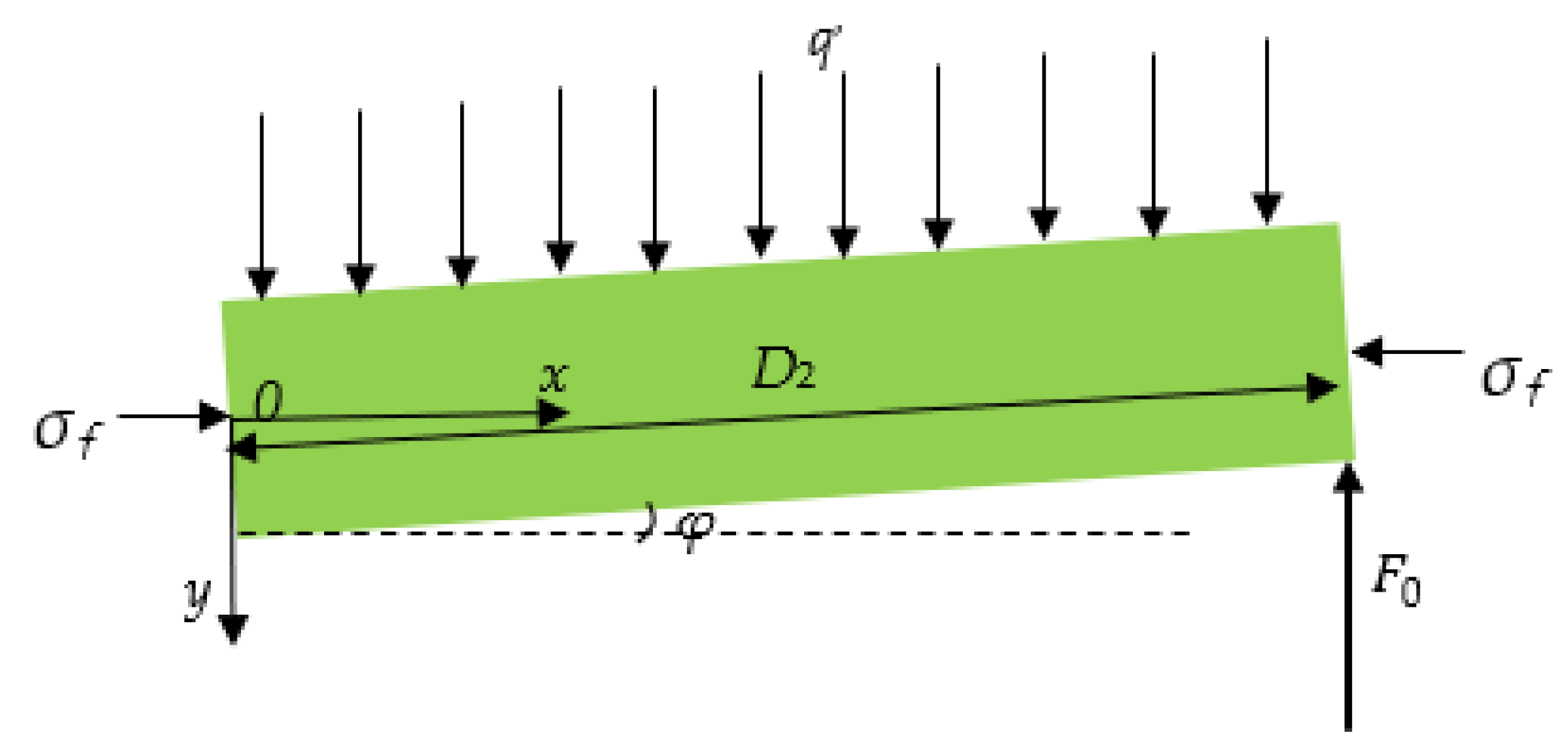
3.1.2. Mechanics Analysis on the Periodic Fracture in the Super-Thick Hard Strata

As shown in Figure 4, after the initial fracture of the thick hard rock, it can be regarded as a homogeneous isotropic cantilever structure. Taking the center point of the cantilever beam as the coordinate origin, the periodic fracture mechanics model of super-thick hard rock is established, as shown in Figure 7.
According to the semi-inverse method of elastic mechanics, the basic form of the stress component of the cantilever beam is obtained, such as Equation (9).
σ x = x 2 6 A y + 2 B 2 + x 6 E y + 2 J 2 A y 3 2 B y 2 + 6 N y + 2 T σ y = A y 3 + B y 2 + C y + D τ x y = x 3 A y 2 + 2 B y + C 3 E y 2 2 J y G
In the Equation, A, B, C, D, E, J, G, N, T are dimensionless undetermined coefficients.
The left side of the cantilever beam is the free end, and the boundary conditions on the right side and the upper and lower sides are as follows (10).
σ y y = h 2 = 0 σ y y = h 2 = q τ xy y = ± h 2 = 0 h 2 h 2 τ xy x = l = 2 ql h 2 h 2 σ x x = l d y = h 2 h 2 σ F d y h 2 h 2 σ x x = l y d y = M 1
In the Equation, L = 2 l ; M 1 is the main moment of the fixed end side of the cantilever beam, M 1 = 2 q + γ h l 2 h 2 h 2 σ F y d y .
According to Equations (9) and (10), the solution is:
A = 2 q h 3 B = 0 C = 3 q 2 h D = q 2 E = 2 ql h 3 J = 0 G = 3 ql 2 h N = 4 γ h + q l 2 h 3 q 10 h T = σ F 2
Substituting the value in Equation (11) into Equation (9), the expression of stress component of cantilever beam is obtained.
σ x = 6 q h 3 x 2 y 12 ql h 3 xy + 4 q h 3 y 3 6 4 γ h + q l 2 h 3 y 3 q 5 h y σ F σ y = 2 q h 3 y 3 + 3 q 2 h y q 2 τ xy = 6 q h 3 xy 2 3 q 2 h x + 6 ql h 3 y 2 3 ql 2 h
For the cantilever beam, the negative bending moment at the support is the largest, and the upper surface of the embedded end beam (x = l, y = −h/2) is first pulled off. At this time, the three stress components of the cantilever beam are σ x 2 , σ y 2 , τ xy 2 . Substitute x = l, y = −h/2 into Equation (12).
σ x 2 = 12 q + γ h l 2 h 2 q 5 σ F σ y 2 = q τ xy 2 = 0
Similarly, if the rock stratum does not break, σ x 2 σ t , thus obtaining the periodic fracture span L n of the extremely thick hard rock stratum:
L n = 2 l = 2 h 5 σ t + 5 σ F + q 60 q + γ h

3.2. Energy Analysis on the Fracture-Type Mine Earthquake in Super Thick Hard Strata

According to the variational method to solve the energy released by the elastic beam fracture, the energy released by the elastic body during the deformation fracture process E p is the sum of the deformation potential energy and the external force potential energy of the elastic body, that is:
E p = U + V
In the Equation, U is the deformation potential energy of the elastomer, and V is the external force potential energy of the elastomer.
U = 1 2 d σ x ε x + σ y ε y + τ xy γ xy d x d y
V = d f x u + f y s d x d y d f ¯ x u + f ¯ y s d S
In the Equation, d is the width of working face, m; ε x , ε y , and γ xy are deformation components of the elastic beam; u and s are the displacement components of the elastic beam, m; f x and f y are the body force components in the elastic beam plane; f ¯ x and f ¯ y are surface force components in the plane of elastic beam; and S is the area of the elastic beam plane, m2.
Because the center of gravity position does not change during the fracture process of the extremely thick hard rock stratum, the physical force does not do work. According to Figure 5 and Figure 6, f x = 0 , f ¯ x = σ F , f ¯ y = q .
According to the physical equations and geometric equations of elastic mechanics, the expressions of the deformation component and displacement component of the elastic beam are obtained as Equations (18) and (19), respectively.
ε x = 1 E σ x v σ y ε y = 1 E σ y v σ x γ xy = 2 1 + v E τ x y
ε x = u x ε y = v y γ xy = v x + u y
It can be seen from the above analysis that the clamped beam is first broken at x = ± l, y = −h/2 under uniform load and horizontal concentrated stress. The expressions of energy E pi released by the initial fracture of extremely thick hard rock strata are obtained by combining the Equations (7), (8) and (15)–(19).
E pi = dL 0 2 E σ t 2 + 2 v q + 2 v qh + 2 σ F L 0 σ t + 2 q 2 h + 2 v σ F qL 0 + q 2
Similarly, by combining Equations (13)–(19), the expressions of energy E pn released by periodic fracture of extremely thick hard rock strata are obtained.
E pn = dL n 2 E σ t 2 + 2 v q + 2 v qh + 2 σ F L n σ t + 2 q 2 h + 2 v σ F qL n + q 2

3.3. Results and Discussion from a Case Study

According to Table 1, there are two thick hard rock strata (the second key stratum and the third key stratum) on the 6306 working face of Dongtan coal mine, H2 = 326.1 m, H 2 = 11 m, H 3 = H3 = 125.9 m; layer thickness is h2 = 263.4 m, h3 = 189.2 m; the distances from the coal seam are h 2 = 86   m , h 3 = 361   m . The distance between the first key stratum and the coal seam is h 1 = 12.4   m , and the buried depth of the coal seam is H = 675.85 m. According to the physical and mechanical properties of rock strata in the 6306 working face, the ultimate tensile strength σ t 2 = 4.66   MPa , elastic modulus E 2 = 26.25   ×   10 3   MPa of the second key strata group; the ultimate tensile strength σ t 3 = 5.22   MPa , elastic modulus E 3 = 20.66   ×   10 3   MPa of the third key layer group. The 6306 working face width d = 261 m, overburden average unit weight   γ = 0.025   MN / m 3 , horizontal stress transfer coefficient is 0.25, the second key layer Poisson’s ratio v 2 = 0.21 , the third key layer Poisson’s ratio v 3 = 0.25 . The above parameters are substituted into Equations (6), (8) and (20), respectively. The initial breaking distance of the second key stratum is L 0 = 384   m and the energy released by the initial breaking is E p 1 = 1.26   ×   10 11   J ; the periodic breaking distance is L n = 191   m and the energy released by periodic breaking E p 2 = 2.12   ×   10 10   J . The initial breaking distance of the third key stratum is L 0 = 286   m and the energy released by the initial breaking is E p 1 = 6.26   ×   10 10   J ; the periodic breaking distance is L n = 125   m and the energy released by the periodic breaking is E p 2 = 1.39   ×   10 10   J .
It can be seen from the calculation results that the energy released by the fracture of the second key stratum is greater than that released by the fracture of the third key stratum. The greater the fracture step of thick hard rock, the higher the energy released during fracture and the greater the magnitude.

4. Study on Mechanism of Ground Vertical Well Hydraulic Fracturing to Prevent and Control Fracture-Type Mine Earthquakes in Thick Hard Rock

Through the above research, it is found that the breaking instability of the thick and hard rock stratum is the main factor causing strong mine earthquakes in the working face, and the large breaking step distance and the energy released after the breaking of the thick and hard rock stratum are the internal causes of strong mine earthquakes. Therefore, an effective way to prevent and control fracture-type mine earthquake in super-thick hard rock strata is the use of reasonable technical means to weaken and modify the super-thick hard rock strata, thus reducing the stress concentration degree of the stope, changing the occurrence state and fracture characteristics of the thick hard rock strata, and reducing the energy released by its fracture instability.
Scholars at home and abroad have found that hydraulic fracturing of extremely thick hard rock strata in surface vertical wells is an effective means of preventing fracture-type mine earthquakes in extremely thick hard rock strata. First of all, the ground hydraulic fracturing of thick hard rock in which the formation of hydraulic fractures destroyed the integrity of thick hard rock; secondly, the hydraulic fracture surface is a weak surface. When the coal seam is mined to a certain length, the hydraulic fracture will be activated after being disturbed by sufficient strength, which will promote the expansion of the gap between the rock masses on both sides of the fracture, and the horizontal concentrated stress is cut off by the fracture. According to Equations (20) and (21), the decrease of fracture step and horizontal concentrated stress will reduce the energy released by the fracture of super-thick hard rock.

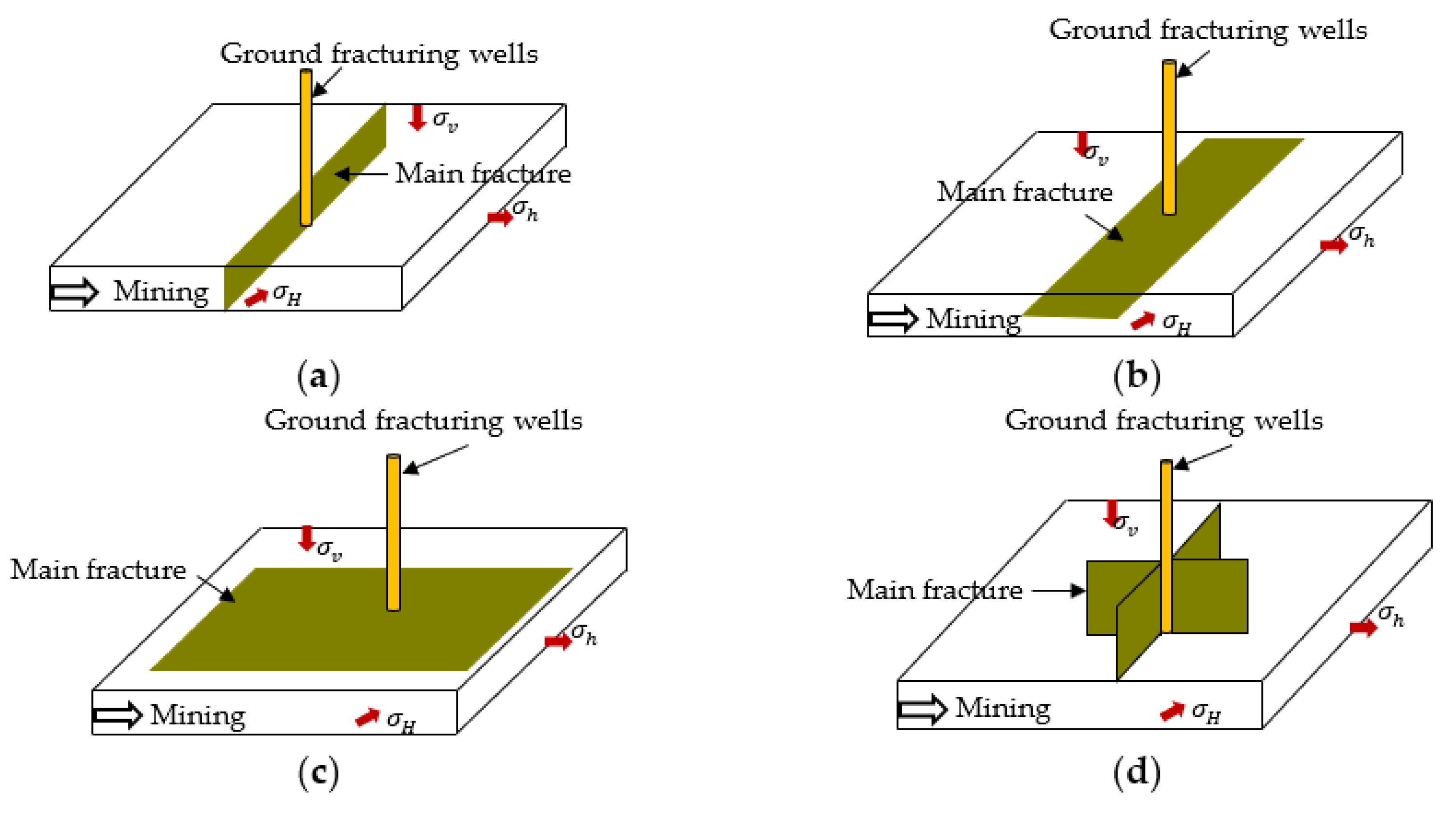
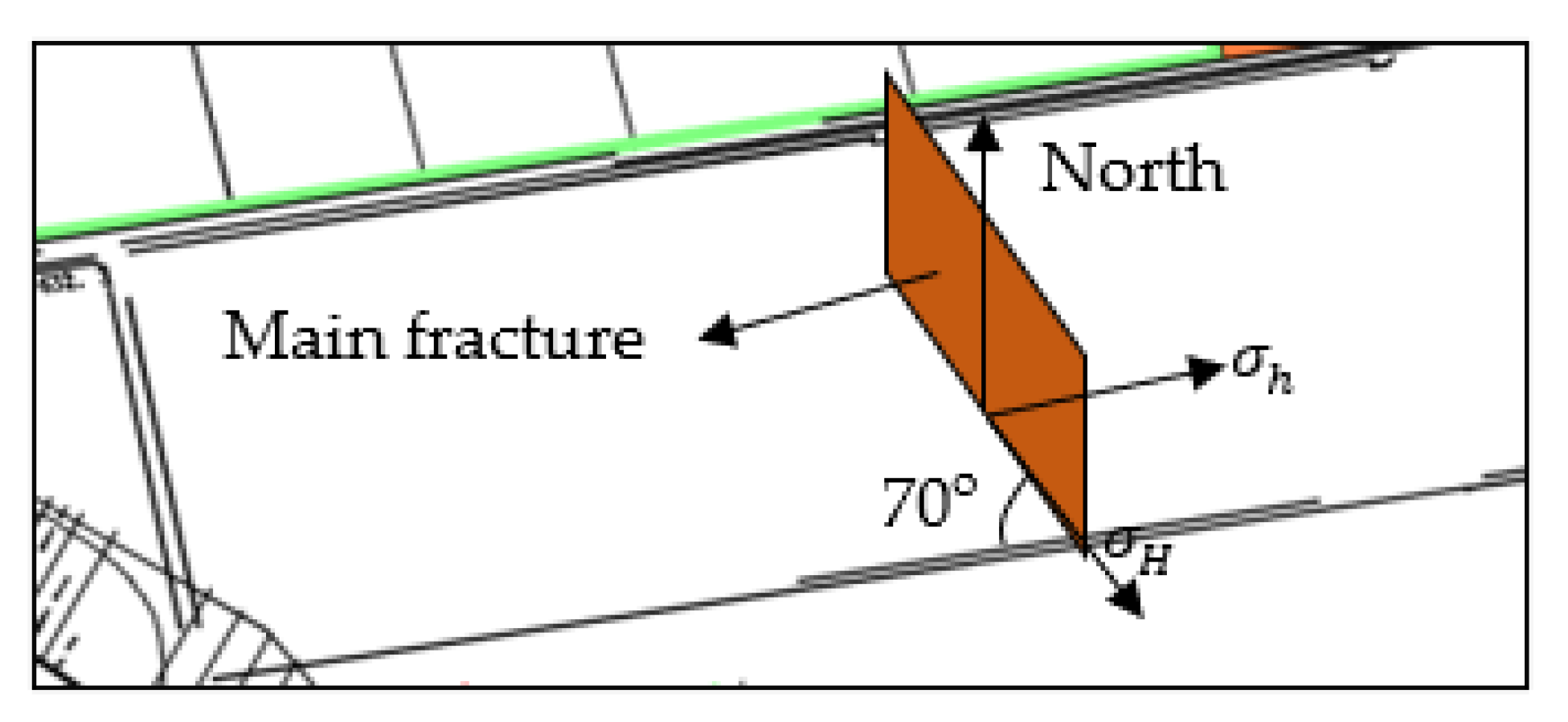
4.1. The Crack Propagation Law of Hydraulic Fracturing by Ground Vertical Well

Through research, it is found that the propagation direction of the main fracture of hydraulic fracturing is always perpendicular to the minimum principal stress and parallel to the maximum principal stress [32]. Therefore, according to the different types of maximum principal stress and minimum principal stress, the types of hydraulic fracturing fracture propagation in the corresponding surface vertical wells can be obtained, as shown in Figure 8.
It can be seen from Figure 8 that when σ H > σ v > σ h , the fracture surface is perpendicular to the advancing direction of the working face and extends along the inclined direction of the working face; when σ H > σ h > σ v , the fracture surface is perpendicular to the gravity direction and extends along the dip direction of the working face; when σ h > σ H > σ v , the fracture surface is perpendicular to the gravity direction and expands along the strike direction of the working face; when σ v > σ H > σ h , the fracture surface is perpendicular to the advancing direction of the working face and extends in the vertical direction; when σ v > σ h > σ H , the fracture surface is perpendicular to the dip direction of the working face and expands in the vertical direction.
According to the in-situ stress test report of the sixth mining area of Dongtan coal mine, the direction of the maximum horizontal principal stress in the sixth mining area is 150°, σ H > σ v > σ h . It can be seen that if ground vertical well hydraulic fracturing is carried out on the overlying hard rock strata of the 6306 working face, the relationship between the crack surface expansion direction and the working face is shown in Figure 9.

4.2. Mechanical Analysis of Super-Thick Hard Rock Strata after Hydraulic Fracturing of Surface Vertical Wells

Through the above analysis, it can be seen that after the ground vertical well hydraulic fracturing of the extremely thick and hard rock stratum, according to the relationship between the spacing of the ground hydraulic fracturing well and the periodic breaking step of the extremely thick and hard rock stratum, the stress state of the extremely thick and hard rock stratum can be divided into two situations:
(1) When the spacing of the ground hydraulic fracturing vertical well is greater than the periodic breaking step of the extremely thick and hard rock stratum, with the increase of the mining distance of the coal seam, the low key stratum above the coal seam collapses layer by layer, making the low key stratum and the extremely thick high key stratum slowly separate, and exposing the extremely thick high key stratum. At this time, the self-weight of the super-thick and high-position key stratum and the overlying weak rock stratum controlled by it are supported by the super-thick and high-position key stratum and the coal and rock mass below it. As shown in Figure 10, when the horizontal stress component is greater than the ultimate tensile strength of the supporting point, the super-thick and high-position key stratum is broken and unstable. In this case, the super-thick and high-position key stratum after fracturing can be simplified as a cantilever beam.
(2) When the distance between the vertical wells of the ground hydraulic fracturing is less than the periodic fracture step distance of the extremely thick and hard rock layer, with the increase of the mining distance of the coal seam, the low rock layer above the coal seam collapses layer by layer. At this time, the weight of the extremely thick and high key layer and the overlying soft rock layer is supported by the extremely thick and high key layer and the gangue below. As shown in Figure 11, with the increase of the mining distance, rotary instability occurs in the extremely thick and high key layer. In the above two cases, because the fracture separates the rock mass on both sides, both sides of the rock mass are not subject to the horizontal stress transferred by the fracture of the lower strata.

4.2.1. The Spacing of Surface Hydraulic Fracturing Wells Is Greater Than the Periodic Fracture Step of Extremely Thick Hard Rock Strata

According to the above analysis and taking the center point of the elastic beam as the origin of the coordinate, the mechanical model of the super-thick hard rock layer after hydraulic fracturing of the ground vertical well is established, as shown in Figure 12.
After the ground vertical well hydraulic fracturing, assuming that the distance between fracturing wells is D1, the extension length of fracture surface is d 0 , and the acute angle between the direction of maximum horizontal principal stress and the strike of working face is θ , then the length of fracture surface along the dip direction is d 0 sin θ . According to Equation (21), under the action of uniform load of overlying strata, initial horizontal stress σ f and supporting stress σ M of lower coal and rock mass, the energy E p n released by fracture at x = l, y = h/2 is:
E p n = d 0 sin θ D 1 2 E σ t 2 + 2 v q + 2 v qh + 2 σ f D 1 σ t + 2 q 2 h + 2 v σ f q D 1 + q 2
σ f = λ γ H i
It can be seen from Equation (22) that when other conditions remain unchanged, the energy released by the fracture of extremely thick hard rock (unfractured part) after hydraulic fracturing of extremely thick hard rock by surface vertical wells is only related to the spacing of fracturing wells.

4.2.2. The Spacing of Surface Hydraulic Fracturing Wells Is Less Than the Periodic Fracture Step of Extremely Thick Hard Rock Strata

From the above analysis, it can be seen that when the spacing of surface hydraulic fracturing wells is less than the periodic fracture step of super-thick hard rock, rotary instability occurs only in super-thick hard rock. In this case, the simplified mechanical model is shown in Figure 13. It can be seen from the figure that the horizontal direction is subjected to the initial horizontal stress σ f ; in the vertical direction, the self-weight stress q of the rock stratum and the overlying rock stratum, and the supporting force F 0 provided by the lower gangue. Taking the center point on the left side of the beam as the coordinate origin, the coordinate system shown in Figure 13 is established.
The slow deformation before the rotary instability of the fractured rock beam is approximately an equilibrium process. Due to the existence of fracturing cracks, the extrusion pressure between the fractured rock beams is approximately 0, and the friction between the fractured rock beams is 0. According to Figure 13, the equilibrium equation in the process of rotary instability is obtained.
F 0 = q + γ h D 2 σ f h D 2 sin φ = 1 2 q + γ h D 2 2
where φ is the rotation angle, °; D 2 is the spacing of fracturing wells, m.
w = D 2 sin φ
In the Equation, w is the rotary subsidence of the fractured rock beam, m.
According to the theory of mine pressure and strata control, the relationship between the maximum rotary subsidence w and the mining height h 0 is approximately:
w 0.3 ~ 0.8 h 0  
According to the law of conservation of energy, the gravitational potential energy of the fractured rock beam is converted into elastic strain energy during the slow rotation of the fractured rock beam.
E p m = w d 0 sin θ q + γ h D 2 2 2 E  
According to Equation (27), the energy released in the process of rotary instability of super-thick and high key strata is only related to the spacing of fractured wells after water fracturing in vertical wells. After water fracturing in the vertical shaft, the fracture times of super-thick high key strata and the frequency of mine earthquakes increase, but the energy released by each fracture decreases and the magnitude of mine earthquakes decreases.

5. Research on Shock Absorption Technology of Ground Vertical Well Hydraulic Fracturing Thick Hard Rock

The existence of extremely thick and hard rock strata provides a target for mine earthquake prevention and control. In order to realize the safe and efficient mining of mines, based on the study of mine earthquake mechanism and fracturing shock absorption in extremely thick and hard rock strata, the shock absorption technology of extremely thick and hard rock strata by hydraulic fracturing of surface vertical wells was proposed, and six surface hydraulic fracturing vertical wells were constructed in Dongtan coal mine.

5.1. Design of Fracturing Well Spacing Based on Controlling Maximum Magnitude

It can be seen from Section 2.3 that the energy released by the initial fracture and periodic fracture of the second key stratum of Dongtan Coal Mine was greater than that released by the fracture of the third key stratum when only the influence of the extremely thick hard rock stratum on the mine earthquake was considered. Therefore, the second key layer was the key target of surface vertical well hydraulic fracturing in Dongtan coal mine. According to the propagation law of hydraulic fracturing cracks in vertical wells on the ground, when the three components of in-situ stress on the working face are σ H > σ v > σ h , the hydraulic fracturing crack surface of vertical wells on the ground is perpendicular to the advancing direction of the working face and extends along the tendency direction of the working face. From Equations (22) and (27), it can be seen that under the condition of constant mining conditions, the energy released by the movement of high key strata is related to the spacing of fracturing wells after the hydraulic fracturing of vertical wells on the ground. Therefore, the relationship between the spacing of ground fracturing wells and the maximum magnitude is also divided into two cases.

5.1.1. The Ground Hydraulic Fracturing Well Spacing Is Greater Than the Thick Hard Rock Periodic Fracture Step

According to the Equation (22), the equation of the spacing of surface hydraulic fracturing wells is derived.
2 σ f σ t + 2 v σ f q D 1 2 + σ t 2 + 2 v q + 2 v qh σ t + 2 q 2 h + q 2 D 1 2 EE p n d 0 sin θ = 0
The roots of (28) are:
D 1 = b + b 2 + 4 ac 2 a a = 2 σ f σ t + 2 v σ f q b = σ t 2 + 2 v q + 2 v qh σ t + 2 q 2 h + q 2 c = 2 EE p n d 0 sin θ
Reference [44] pointed out that only 0.26~3.60% of the energy released by the fracture of key strata diverged in the form of seismic waves. Assuming that η times the energy is converted into seismic waves, the seismic energy released by the key layer fracture is E Sn .
E S n = η E p n
The expression between surface wave magnitude M S and energy is:
lg E S = 4.8 + 1.05 M S
According to the literature [45], the relationship between the near-earthquake magnitude M L in North China and the surface wave magnitude M S existence Equation (32).
M L = M S + 1.08 1.13
The Expressions (30)–(32) are substituted into c , and the expression of the spacing D 1 of the ground fracturing vertical well is obtained.
c = 2 E × 10 3.18 + 1.70 M L η d 0 sin θ
In the equation, M L is the preset maximum magnitude in the process of coal seam mining.
The mechanical parameters of the second key layer of the Section 2.3 6306 working face are substituted into the Equation (33), η = 1 % , θ = 70 o . According to the conclusion in the literature [46], the fracture length of ground vertical well hydraulic fracturing is 220~300 m, where d 0 takes the mean value of 260 m, and the ground hydraulic fracturing well spacing is obtained. When the distance is greater than the periodic fracture step distance of the thick and hard rock layer, the fracturing well spacing based on the prevention and control of the mine earthquake level is shown in Table 2.
According to the previous analysis, the magnitude of earthquakes in the sixth mining area of Dongtan coal mine is above 1.5 ML and mine earthquakes in the thick and hard rock layer accounts for 64.40%. Therefore, the spacing of the fracturing wells in the 6306 working face is 84.94 m. According to the calculation results of Section 2.3, the periodic breaking step of the second key layer is 191 m. In this case, the minimum spacing of fracturing wells is 191 m, because Equation (29) is established when the spacing of fracturing wells is not less than the periodic breaking step distance of the key layer with huge thickness and high position.

5.1.2. The Ground Hydraulic Fracturing Well Spacing Is Less Than the Thick Hard Rock Periodic Fracture Step

According to Equation (27), the equation of the spacing of surface hydraulic fracturing wells is derived.
D 2 = 2 E E pm wd 0 sin θ q + γ h
Combined with Equations (29)–(34), the relationship between the spacing of surface hydraulic fracturing wells and the magnitude is obtained.
D 2 = 2 E × 10 3.18 + 1.70 M L η w d 0 sin θ q + γ h
The mechanical parameters of the second key layer of the Section 2.3 6306 working face are substituted into the Equation (35), w takes 0.3   h 0 . When the ground hydraulic fracturing well spacing is less than the periodic fracture step distance of the thick and hard rock layer, the fracturing well spacing corresponding to the mine earthquake level is calculated, as shown in Table 3.
According to the above analysis, the maximum magnitude allowed in the sixth mining area of Dongtan Coal Mine is 1.5 ML, so the spacing of fracturing wells in the 6306 working face is 28.63 m. According to the conclusion in Reference [46], the extension range of water-fracturing fracture surfaces in surface vertical wells is 100 m~150 m. In order to make the fracturing effect reach the expected effect and to ensure that the fracturing fractures do not affect each other, the spacing of fracturing wells should not be less than 100 m. Therefore, in this case, the 6306 working face fracturing well spacing range is of 100~125 m.
According to the calculation results of ground fracturing well spacing under two working conditions, the optimum fracturing well spacing of the 6306 working face should be 100 m. However, through field investigation, if the location of the fracturing well is completely arranged according to the theoretical calculation results, it is inconvenient for personnel and equipment to enter the construction site, and the site belongs to different villages. In order to reduce the cost of land acquisition and the convenience of construction, the theoretical layout scheme is slightly adjusted. Finally, the layout scheme of the ground hydraulic fracturing well in the 6306 working face of Dongtan Coal Mine is shown in Figure 14.

5.2. Damping Effect Verification of Ground Vertical Well Hydraulic Fracturing

According to the layout scheme of ground hydraulic fracturing wells in Figure 14, the industrial test of ground vertical well hydraulic fracturing was carried out on the second and third key layers above the 6306 working face. During the fracturing period, the fracture height and range of No.1~No.4 fracturing wells were monitored by high-precision microseismic, and the fracture height and range of No.5 and No.6 fracturing wells were monitored by interwell. The monitoring results are shown in Table 4.
According to Table 4, the fracture direction of the ground vertical well fracturing is basically the same as the direction of the maximum principal stress (NE150°), and the average length of the fracture surface is 257.25 m. The hydraulic fracturing of the second and third key strata is realized in the vertical direction.
In the process of stoping 0~700 m in the 6304, 6305, and 6306 working faces, mine earthquakes whose source positions were above the coal seam 86 m (the second key stratum is 86 m from the coal seam) and greater than 1.5 ML were counted. The footage of the working face and the cumulative frequency of mine earthquakes are shown in Figure 15, and the footage of the working face and the cumulative total energy of mine earthquakes are shown in Figure 16.
It can be seen from Figure 15 that in the process of mining 700 m, mine earthquakes occurred in the thick and hard rock strata with magnitudes greater than 1.5 ML. There were 66 events in the 6304 working face, 100 events in the 6305 working face and 30 events in the 6306 working face. Ground vertical well hydraulic fracturing technology can significantly reduce the frequency of high energy mine earthquakes, 6306 working face than 6304 working face decreased by 54.55%, than 6305 working face decreased by 70%. From the point of view of the occurrence time of the mine earthquakes, the 6304 working face was pushed to 52.85 m for the first time to have a mine earthquake of 1.5 ML or more, the 6305 working face was pushed to 38.53 m for the first time to have a mine earthquake of 1.5 ML or more, and the 6306 working face was pushed to 216.75 m for the first time to have a mine earthquake of 1.5 ML or more.
It can be seen from Figure 16 that the hydraulic fracturing technology of surface vertical wells can significantly reduce the energy released by the fracture of extremely thick hard rock strata. In the process of mining 700 m, the total energy of the 6304 working face was 6.87 × 10⁷ J, the total energy of the 6305 working face was 8.59 × 10⁷ J, and the total energy of the 6306 working face was 1.29 × 10⁷ J. Among them, 6306 working face than 6304 working face decreased by 81.22%, compared with 6305 working face decreased by 84.98%.
In summary, the ground vertical well hydraulic fracturing of thick hard rock can significantly reduce the frequency of thick hard rock fracture-induced mine earthquakes and reduce the total energy of mine earthquakes. However, because the movement process of extremely thick hard rock strata includes bending, deformation, fracture, rotation, and slip, ground vertical well hydraulic fracturing technology has a significant damping effect on the extremely thick hard rock strata fracture-type mine earthquake, but it cannot prevent and control the occurrence of reverse-transformation mine earthquakes or slip-type mine earthquakes.

6. Conclusions

In view of the frequent occurrence of fracture-type mine earthquakes in the giant thick hard rock formation in Chinese coal mines, the mechanism of mine earthquakes in the giant thick hard rock formation and the seismic absorption technology of hydraulic fracturing in the ground vertical well were studied by using the methods of field investigation, theoretical analysis, industrial tests, and field monitoring. The main conclusions are as follows:
(1) The fracture-type of huge thick hard rock strata is divided into four types, namely, low low-energy ore earthquake, low high-energy ore earthquake, high low-energy ore earthquake and high high-energy ore earthquake. Among them, the proportion of high and low energy ore shocks and high and high energy ore shocks was the largest in the thick hard rock stratum mine.
(2) By establishing the mechanical model of clamped beam and cantilever beam under the influence of horizontal concentrated stress, the fracture step equation and energy release equation of extremely thick hard rock were derived by semi-inverse method and variational method. The greater the fracture step of thick hard rock, the higher the energy released during fracture and the greater the magnitude.
(3) By establishing the mechanical model of ground vertical well after hydraulic fracturing of extremely thick and hard rock, the relationship between ground vertical well spacing and maximum mine earthquake magnitude was deduced, and the design of fracturing well based on controlling the maximum earthquake magnitude in the 6306 working face was completed.
(4) The surface vertical well hydraulic fracturing technology can significantly reduce the frequency of fracture-type mine earthquakes in thick hard rock and reduce the total energy of mine earthquakes, but it can not prevent and control the occurrence of reverse-transformation mine earthquakes and slip-type mine earthquakes. The occurrence frequency of mine earthquakes above 1.5 ML in the 6306 working face was 54.55% less than that in the 6304 working face and 70% less than that in the 6305 working face. The total energy of mine earthquakes in the 6306 working face was 81.22% lower than that in the 6304 working face and 84.98% lower than that in the 6305 working face.

Author Contributions

Conceptualization, S.Z. and F.J.; methodology, X.S. (Shang Xiaoguang); software, J.L. (Jinhai Liu) and J.L. (Jiajie Li); validation, X.S. (Shang Xiaoguang), X.Z. and C.W.; formal analysis, X.S. (Shang Xiaoguang); investigation, X.S. (Shang Xiaoguang).; resources, X.S. (Xiang Sun).and Y.C., B.X. and X.Q.; data curation, S.Z.; writing—original draft preparation, X.S. (Shang Xiaoguang); writing—review and editing, X.S. (Shang Xiaoguang); visualization, J.L. (Jiajie Li); supervision, S.Z.; project administration, F.J. and S.Z.; funding acquisition, F.J. and S.Z. All authors have read and agreed to the published version of the manuscript.

Funding

This study was funded by the National Natural Science Foundation of China, grant numbers 51904017 and 52004021; the State Key Research Development Program of China, grant number 2022YFC3004604; the Major Science and Technology Innovation Project of Shandong Province, grant number No. 2019SDZY02; the Young Talents Lifting Project of China Association for Science and Technology, grant number 2021QNRC001; Fundamental Research Funds for the Central Universities and the Youth Teacher International Exchange & Growth Program, grant number QNXM20220003; and 111 Project, grant number B20041.

Institutional Review Board Statement

Not applicable.

Informed Consent Statement

Not applicable.

Data Availability Statement

The data used to support the findings of this study are available from the corresponding author upon request.

Acknowledgments

The Journal editors and reviewers are acknowledgments for their comments.

Conflicts of Interest

The authors declare no conflict of interest.

References

  1. Wei, C.; Zhang, C.; Canbulat, I.; Cao, A.; Dou, L. Evaluation of current coal burst control techniques and development of a coal burst management framework. Tunn. Undergr. Space Technol. 2018, 81, 129–143. [Google Scholar] [CrossRef]
  2. Wasilewski, S. Gas-dynamic phenomena caused by rock mass tremors and rock bursts. Int. J. Min. Sci. Technol. 2020, 30, 413–420. [Google Scholar] [CrossRef]
  3. Wang, J.; Ning, J.; Qiu, P.; Shang, Y.; Shang, H. Microseismic monitoring and its precursory parameter of hard roof collapse in longwall faces: A case study. Geomech. Eng. 2019, 17, 375–383. [Google Scholar] [CrossRef]
  4. Zhang, M.; Jiang, F. Rock burst criteria and control based on an abutment-stress-transfer model in deep coal roadways. Energy Sci. Eng. 2020, 8, 2966–2975. [Google Scholar] [CrossRef]
  5. Dou, L.; Cao, J.; Cao, A.; Chai, Y.; Bai, J.; Kan, J. Research on types of coal mine tremor and propagation law of shock waves. Coal Sci. Technol. 2021, 49, 23–31. [Google Scholar] [CrossRef]
  6. Jiang, L.; Wu, Q.; Wu, Q.; Wang, P.; Xue, Y.; Kong, P.; Gong, B. Fracture failure analysis of hard and thick key layer and its dynamic response characteristics. Eng. Fail. Anal. 2019, 98, 118–130. [Google Scholar] [CrossRef]
  7. Ning, J.; Wang, J.; Jiang, L.; Jiang, N.; Liu, X.; Jiang, J. Fracture analysis of double-layer hard and thick roof and the controlling effect on strata behavior: A case study. Eng. Fail. Anal. 2017, 81, 117–134. [Google Scholar] [CrossRef]
  8. Yang, Z.; Liu, C.; Tang, S.; Dou, L.; Cao, J. Rock burst mechanism analysis in an advanced segment of gob-side entry under different dip angles of the seam and prevention technology. Int. J. Min. Sci. Technol. 2018, 28, 891–899. [Google Scholar] [CrossRef]
  9. Li, D.; Zhang, J. Rockburst Monitoring in Deep Coalmines with Protective Coal Panels Using Integrated Microseismic and Computed Tomography Methods. Shock. Vib. 2020, 2020, 8831351. [Google Scholar] [CrossRef]
  10. Urbancic, T.I.; Trifu, C.I. Recent advances in seismic monitoring technology at Canadian mines. J. Appl. Geophys. 2000, 45, 225–237. [Google Scholar] [CrossRef]
  11. Driad-Lebeau, L.; Lahaie, F.; Al Heib, M.; Josien, J.P.; Bigarré, P.; Noirel, J.F. Seismic and geotechnical investigations following a rockburst in a complex French mining district. Int. J. Coal Geol. 2005, 64, 66–78. [Google Scholar] [CrossRef]
  12. Zhu, S.; Feng, Y.; Jiang, F. Determination of Abutment Pressure in Coal Mines with Extremely Thick Alluvium Stratum: A Typical Kind of Rockburst Mines in China. Rock Mech. Rock Eng. 2015, 49, 1943–1952. [Google Scholar] [CrossRef]
  13. Zhang, M.; Zhang, J.; Jiang, F.; Jiao, Z. Design of rib pillars in deep longwall mines based on rockburst and water-seepage prevention. Energy Sci. Eng. 2020, 9, 256–266. [Google Scholar] [CrossRef]
  14. Wu, J.; Meng, X.R.; Jiang, Y.D. Development of longwall top-coal caving technology in China. In Proceedings of the International Workshop on Underground Thick-Seam Mining, Beijing, China, 15 April 1999; Volume 6, pp. 101–112. [Google Scholar]
  15. Yu, B.; Zhang, L. Study on the abutment pressure distribution in top coal caving. Arab. J. Geosci. 2020, 13, 162. [Google Scholar] [CrossRef]
  16. Pengfei, L.; Xinyang, B.; Gang, L.; Xuehua, C.; Gong, F. Research on Fault Activation Law in Deep Mining Face and Mechanism of Rockburst Induced by Fault Activation. Adv. Civ. Eng. 2020, 2020, 8854467. [Google Scholar] [CrossRef]
  17. Rong, H.; Yu, S.; Zhang, H.; Liang, B. Quantitative Calculation of Critical Depth in Typical Rockburst Mine. Adv. Civ. Eng. 2020, 2020, 7968160. [Google Scholar] [CrossRef]
  18. Dong, G.; Liang, X.; Wang, Z. The Properties of a Coal Body and Prediction of Compound Coal-Rock Dynamic Disasters. Shock. Vib. 2020, 2020, 8830371. [Google Scholar] [CrossRef]
  19. Guo, J.; Ma, L.; Ju, F.; Zhang, C.; Wang, F.; Guo, S. Mechanism of Dynamic Failure in Roadways with Thick and Competent Roof Strata: A Case Study. Adv. Civ. Eng. 2019, 2019, 2618543. [Google Scholar] [CrossRef]
  20. He, S.; Song, D.; Li, Z.; He, X.; Chen, J.; Zhong, T.; Lou, Q. Mechanism and Prevention of Rockburst in Steeply Inclined and Extremely Thick Coal Seams for Fully Mechanized Top-Coal Caving Mining and Under Gob Filling Conditions. Energies 2020, 13, 1362. [Google Scholar] [CrossRef]
  21. Lyu, P.; Chen, X.; Chen, G.; Qiu, L. Experimental study on dynamic mechanical responses of coal specimens under the combined dynamic-static loading. Arab. J. Geosci. 2020, 13, 935. [Google Scholar] [CrossRef]
  22. Zhou, H.; Meng, F.; Zhang, C.; Hu, D.; Yang, F.; Lu, J. Analysis of rockburst mechanisms induced by structural planes in deep tunnels. Bull. Eng. Geol. Environ. 2014, 74, 1435–1451. [Google Scholar] [CrossRef]
  23. Sainoki, A.; Mitri, H.S. Simulating intense shock pulses due to asperities during fault-slip. J. Appl. Geophys. 2014, 103, 71–81. [Google Scholar] [CrossRef]
  24. Jiang, L.; Wang, P.; Zheng, P.; Luan, H.; Zhang, C. Influence of Different Advancing Directions on Mining Effect Caused by a Fault. Adv. Civ. Eng. 2019, 2019, 7306850. [Google Scholar] [CrossRef]
  25. Yang, Z.; Liu, C.; Zhu, H.; Xie, F.; Dou, L.; Chen, J. Mechanism of rock burst caused by fracture of key strata during irregular working face mining and its prevention methods. Int. J. Min. Sci. Technol. 2019, 29, 889–897. [Google Scholar] [CrossRef]
  26. Cai, W.; Dou, L.; Li, Z.; He, J.; He, H.; Ding, Y. Mechanical Initiation and Propagation Mechanism of a Thrust Fault: A Case Study of the Yima Section of the Xiashi-Yima Thrust (North Side of the Eastern Qinling Orogen, China). Rock Mech. Rock Eng. 2014, 48, 1927–1945. [Google Scholar] [CrossRef]
  27. Prusek, S.; Masny, W. Analysis of damage to underground workings and their supports caused by dynamic phenomena. J. Min. Sci. 2015, 51, 63–72. [Google Scholar] [CrossRef]
  28. Carpinteri, A.; Borla, O. Acoustic, electromagnetic, and neutron emissions as seismic precursors: The lunar periodicity of low-magnitude seismic swarms. Eng. Fract. Mech. 2019, 210, 29–41. [Google Scholar] [CrossRef]
  29. Brace, W.F.; Byerlee, J.D. Stick-slip as a mechanism forearthquakes. Science 1966, 153, 990–992. [Google Scholar] [CrossRef]
  30. Cong, Z.; Li, Y.; Tang, J.; Martyushev, D.A.; Hu, B.; Yang, F. Numerical simulation of hydraulic fracture height layer-through propagation based on three-dimensional lattice method. Eng. Fract. Mech. 2022, 264, 108331. [Google Scholar] [CrossRef]
  31. Martyushev, D.A.; Galkin, S.V.; Shelepov, V.V. The influence of the rock stress state on matrix and fracture permeability under conditions of various lithofacial zones of the tournaisian-fammenian oil fields in the Upper Kama Region. Mosc. Univ. Geol. Bull. 2019, 74, 573–581. [Google Scholar] [CrossRef]
  32. Ponomareva, I.N.; Martyushev, D.A. Evaluation of hydraulic fracturing results based on the analysis of geological field data. Georesursy 2020, 22, 8–14. [Google Scholar] [CrossRef]
  33. Martyushev, D.A. Rock stress state influence on permeability of carbonate reservoirs. Bull. Tomsk. Polytech. Univ. Geo Assets Eng. 2020, 331, 24–33. [Google Scholar]
  34. Zhu, Q.; Feng, Y.; Cai, M.; Liu, J.; Wang, H. Interpretation of the extent of hydraulic fracturing for rockburst prevention using microseismic monitoring data. J. Nat. Gas Sci. Eng. 2017, 38, 107–119. [Google Scholar] [CrossRef]
  35. Kang, H.; Zhang, X.; Si, L.; Wu, Y.; Gao, F. In-situ stress measurements and stress distribution characteristics in underground coal mines in China. Eng. Geol. 2010, 116, 333–345. [Google Scholar] [CrossRef]
  36. Ma, D.; Duan, H.; Zhang, Q.; Zhang, J.; Li, W.; Zhou, Z.; Liu, W. A Numerical Gas Fracturing Model of Coupled Thermal, Flowing and Mechanical Effects. Comput. Mater. Contin. 2020, 65, 2123–2141. [Google Scholar] [CrossRef]
  37. Figueiredo, B.; Tsang, C.-F.; Rutqvist, J.; Niemi, A. Study of hydraulic fracturing processes in shale formations with complex geological settings. J. Pet. Sci. Eng. 2017, 152, 361–374. [Google Scholar] [CrossRef]
  38. Ge, Z.; Mei, X.; Lu, Y.; Tang, J.; Xia, B. Optimization and application of sealing material and sealing length for hydraulic fracturing borehole in underground coal mines. Arab. J. Geosci. 2014, 8, 3477–3490. [Google Scholar] [CrossRef]
  39. Lu, Y.; Cheng, L.; Ge, Z.; Xia, B.; Li, Q.; Chen, J. Analysis on the Initial Cracking Parameters of Cross-Measure Hydraulic Fracture in Underground Coal Mines. Energies 2015, 8, 6977–6994. [Google Scholar] [CrossRef]
  40. Cong, L.; Jianqiang, D.; Yaoru, L.; Qiang, Y.; Hongfei, D. Experiment simulation of hydraulic fracture in colliery hard roof control. J. Pet. Sci. Eng. 2016, 138, 265–271. [Google Scholar] [CrossRef]
  41. Xu, J.; Zhai, C.; Qin, L. Mechanism and application of pulse hydraulic fracturing in improving drainage of coalbed methane. J. Nat. Gas Sci. Eng. 2017, 40, 79–90. [Google Scholar] [CrossRef]
  42. Xu, Z. A Concise Course of Elastic Mechanics; Higher Education Press: Beijing, China, 2001; pp. 46–51. [Google Scholar]
  43. Zhang, M.; Jiang, F.; Chen, G.; Jiao, Z.; Hu, H.; Chen, B. Stope stress transfer model based on the motion state of thick and hard rock strata and its application. J. Rock Mech. Eng. 2020, 39, 1396–1407. [Google Scholar] [CrossRef]
  44. Zhang, M.; Jiang, F.; Li, K.; Sun, C.; Zhai, M. Research on ground motion damage boundary based on breaking of thick and hard key strata. J. China Univ. Min. Technol. 2017, 46, 514–520+536. [Google Scholar] [CrossRef]
  45. Jin, H.; Yan, X.; Ren, L.; Cao, C. A preliminary study on the empirical relationship between near-earthquake magnitude and surface wave magnitude in Xinjiang. Inland Earthq. 2021, 35, 150–156. [Google Scholar]
  46. Shang, X.; Zhu, S.; Jiang, F.; Zhang, X.; Wang, C.; Wang, C.; Xie, H.; Yan, X.; Liu, J.; Wei, Q. Experimental study on prevention and control of super thick hard rock movement-type mine earthquake by ground vertical well hydraulic fracturing. Coal J. 2021, 46, 639–650. [Google Scholar] [CrossRef]
Figure 1. Location map of the sixth mining area of Dongtan Coal Mine.
Sustainability 15 05122 g001
Figure 2. Dongtan coal mine six mining area working face layout diagram.
Sustainability 15 05122 g002
Figure 3. Divide the key layers.
Sustainability 15 05122 g003
Figure 4. Initial fracture mechanics model of thick hard rock.
Sustainability 15 05122 g004
Figure 5. Periodic fracture mechanics model of thick hard rock.
Sustainability 15 05122 g005
Figure 6. Mechanics model of fixed beam.
Sustainability 15 05122 g006
Figure 7. Mechanical model of cantilever beam.
Sustainability 15 05122 g007
Figure 8. Surface vertical well hydraulic fracturing fracture propagation form: (a) σ H > σ v > σ h ; (b) σ H > σ h > σ v ; (c) σ h > σ H > σ v ; (d) σ v > σ H > σ h and σ v > σ h > σ H .
Sustainability 15 05122 g008
Figure 9. The main fracture propagation form of ground vertical well fracturing in the 6306 working face.
Sustainability 15 05122 g009
Figure 10. Mechanical model of cantilever beam after hydraulic fracturing of surface vertical wells.
Sustainability 15 05122 g010
Figure 11. Mechanical model of rotary instability of high key strata after hydraulic fracturing of surface vertical wells.
Sustainability 15 05122 g011
Figure 12. Mechanical model of cantilever beam after hydraulic fracturing of surface vertical well.
Sustainability 15 05122 g012
Figure 13. Mechanical analysis of rotary instability of high key strata after hydraulic fracturing of surface vertical wells.
Sustainability 15 05122 g013
Figure 14. The actual position of ground hydraulic fracturing vertical well in 6306 working face.
Sustainability 15 05122 g014
Figure 15. Cumulative frequency of mine earthquakes above 1.5 ML.
Sustainability 15 05122 g015
Figure 16. Accumulated total energy of mine earthquake above 1.5 ML.
Sustainability 15 05122 g016
Table 1. O2-D7 borehole formation parameters.
NumberingRockThickness/m
23Quaternary topsoil layer125.9
22sandstone group189.2
21sandy mudstone1.5
20sandstone8.2
19sandy mudstone1.3
18sandstone group263.4
17sandy mudstone12.6
16sandstone1.25
15mudstone0.95
14sandstone0.9
13mudstone4.4
12sandstone9.9
11sandy mudstone9
10mudstone2.05
9sandstone group29
8mudstone3.3
72 coal1.7
6mudstone1.6
5sandstone3.9
4medium-grained sandstone0.8
3fine sandstone2.5
2medium-grained sandstone0.5
1sandstone2.0
03 coal5.4
Table 2. The fracturing well spacing corresponding to the maximum magnitude when the fracturing well spacing is greater than the key layer periodic fracture step.
Magnitude/MLFracturing Well Spacing/m
1.584.94
1.6104.42
1.7128.12
1.8156.95
1.9192.03
2.0234.69
Table 3. The spacing of fracturing wells corresponding to different maximum magnitudes when the spacing of fracturing wells is less than the periodic fracture step of key strata.
Magnitude/MLFracturing Well Spacing/m
1.546.74
1.656.85
1.769.14
1.884.08
1.9102.27
2.0124.38
Table 4. Table is showing monitoring results.
Fracturing Well NumberMain Crack Direction/oFracture Length/mRange of Slit Height/m
1NE143219−194~−530 m
2NE145240−213.8~−558.15
3NE147300−190~−490
4NE150270−200~−530
5NE127496.5−382~−540
6NE134487.5−304~−608
Disclaimer/Publisher’s Note: The statements, opinions and data contained in all publications are solely those of the individual author(s) and contributor(s) and not of MDPI and/or the editor(s). MDPI and/or the editor(s) disclaim responsibility for any injury to people or property resulting from any ideas, methods, instructions or products referred to in the content.

