
CFD Analysis of the Heat Transfer and Fluid Flow Characteristics Using the Rectangular Rib Attached to the Fin Surface in a Solar Air Heater


Abstract
:1. Introduction
2. Methodology
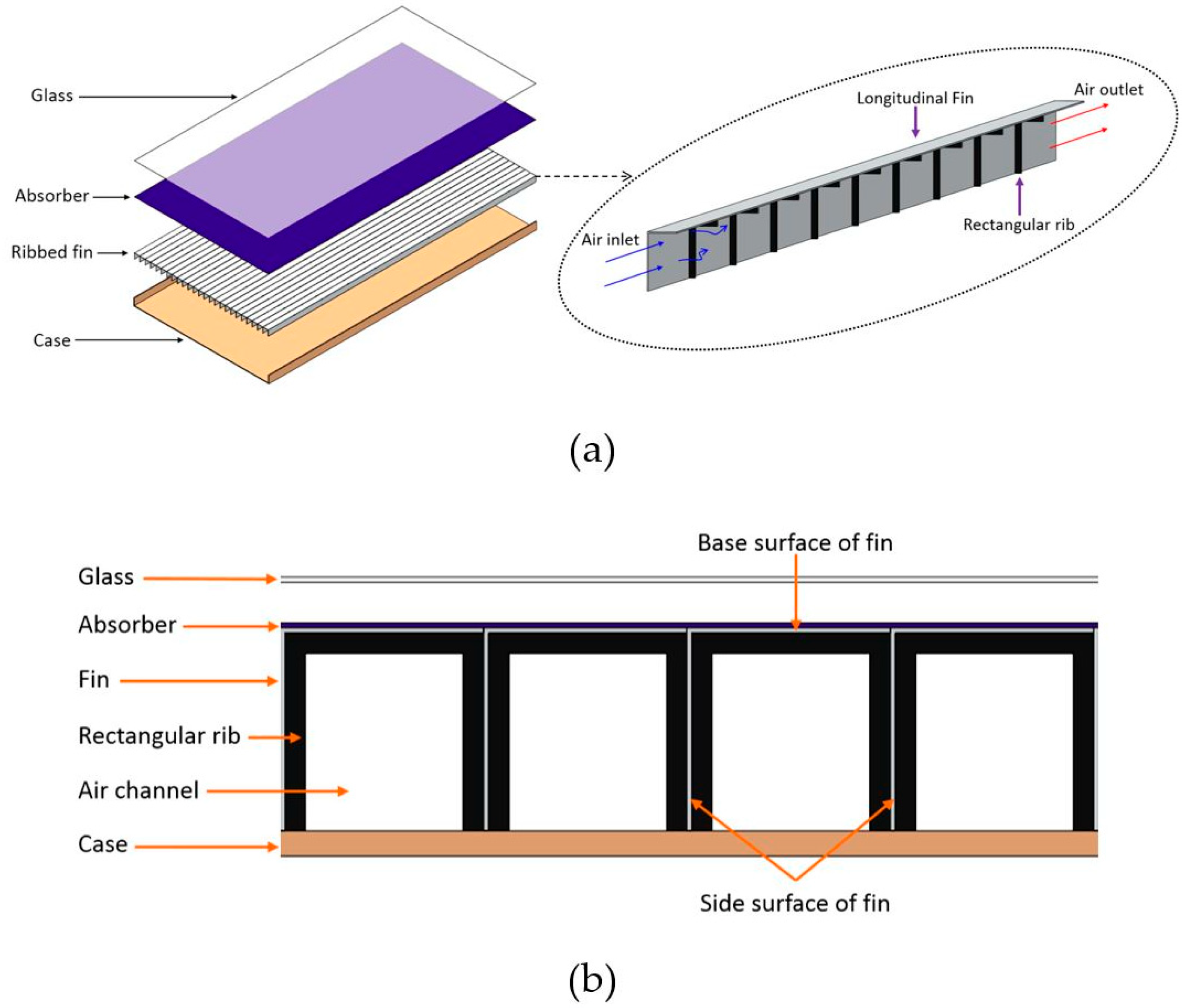
2.1. Description of the Model
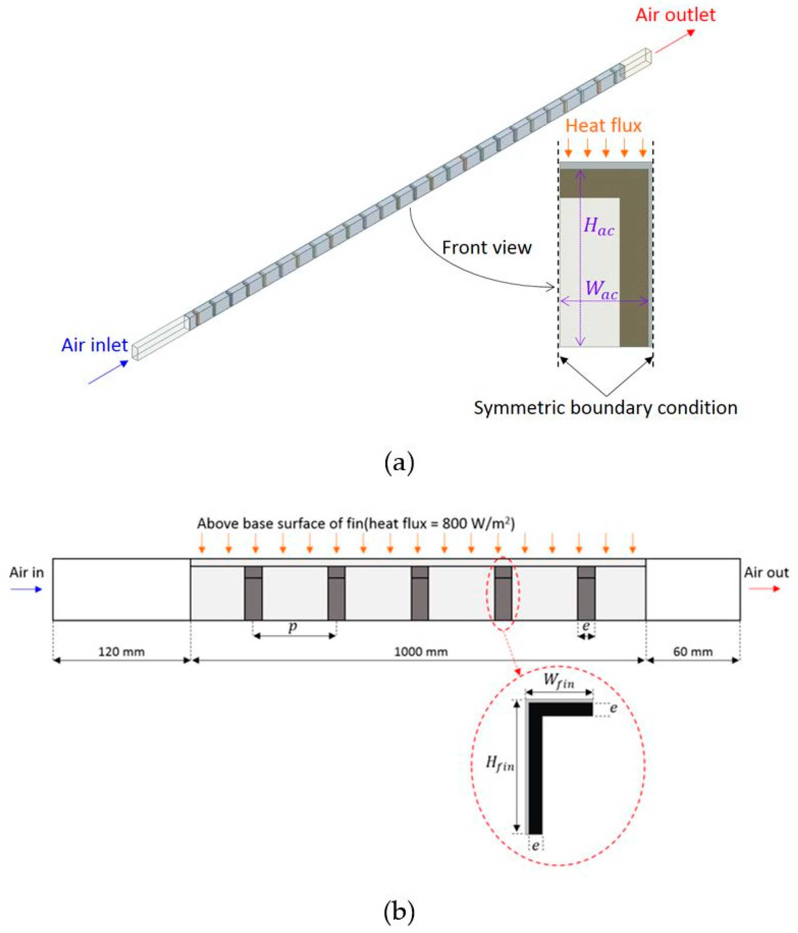
2.2. Boundary Condition
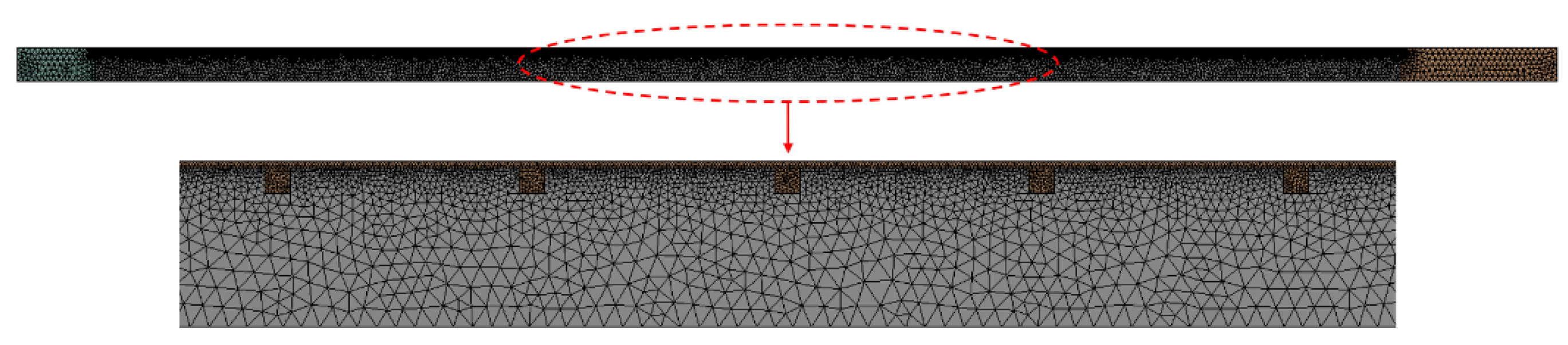
2.3. Grid Generation and Independence
2.4. Solution Method
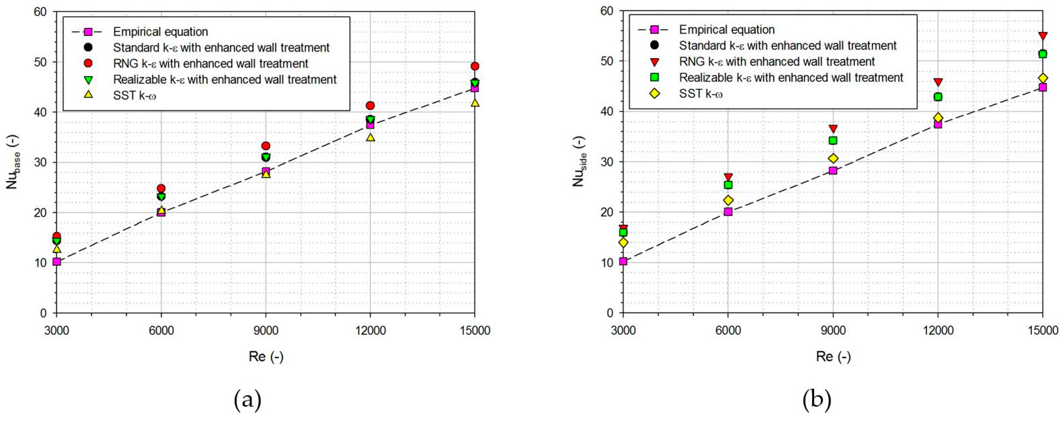
2.5. Turbulence Model
2.6. Performance Indicators
3. Results and Discussion
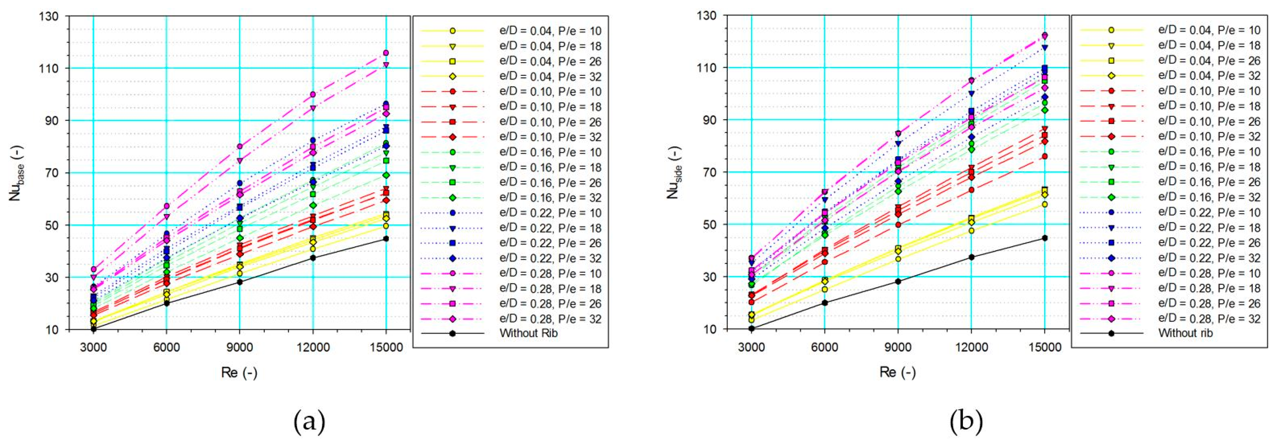
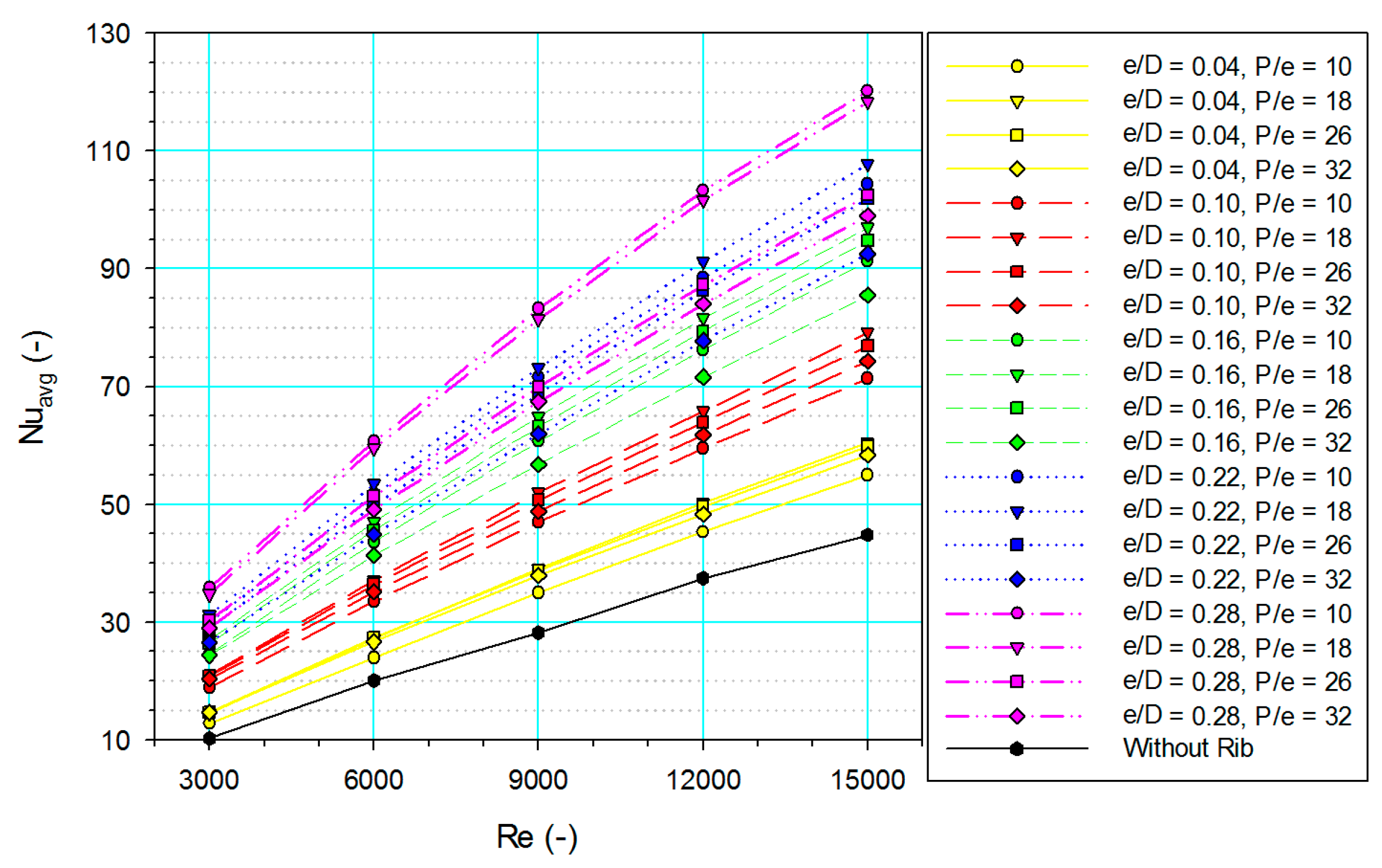
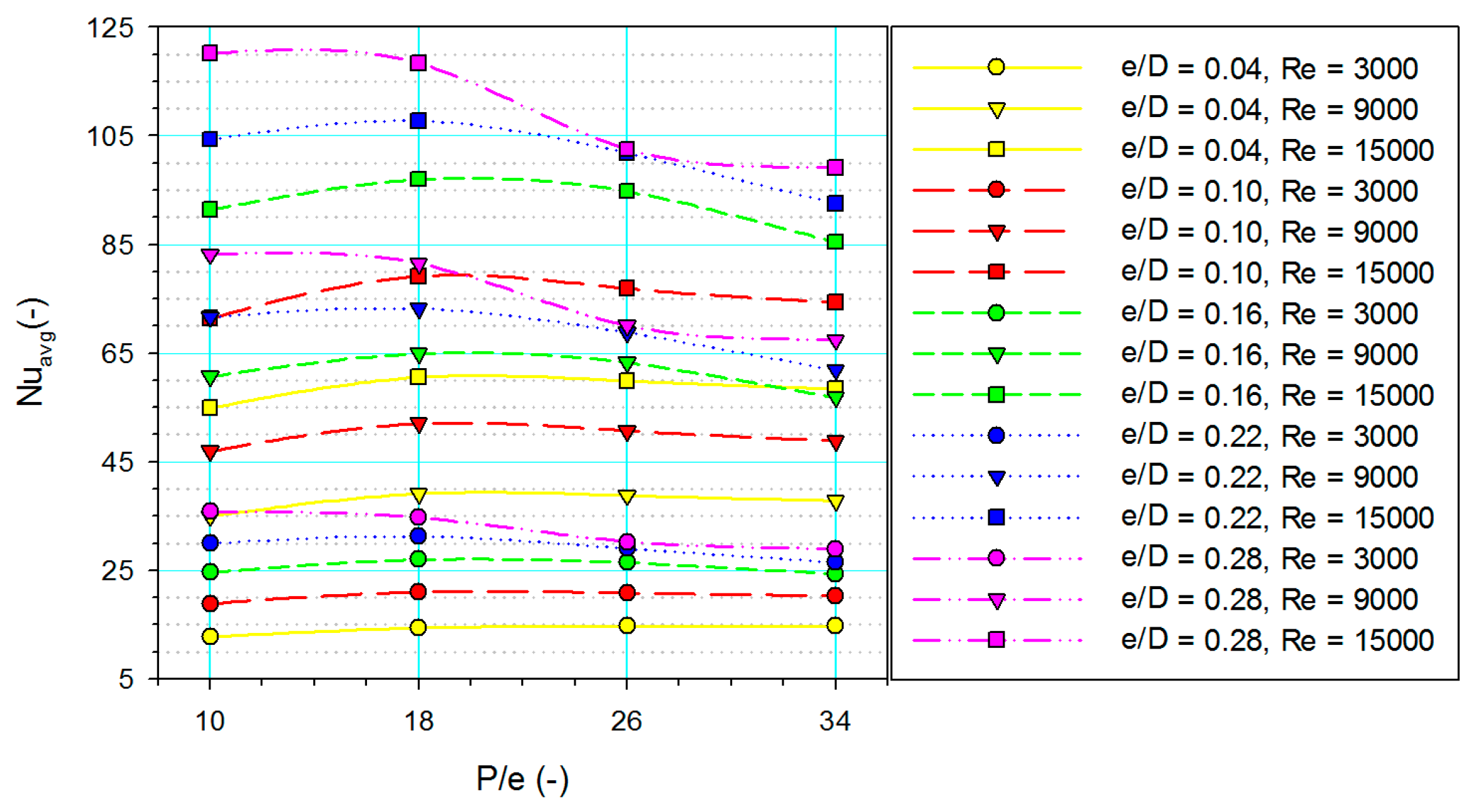
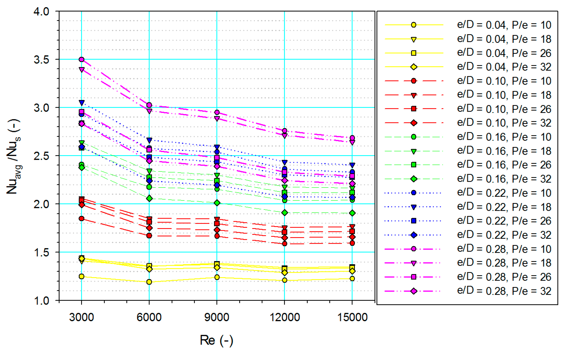
3.1. Heat Transfer
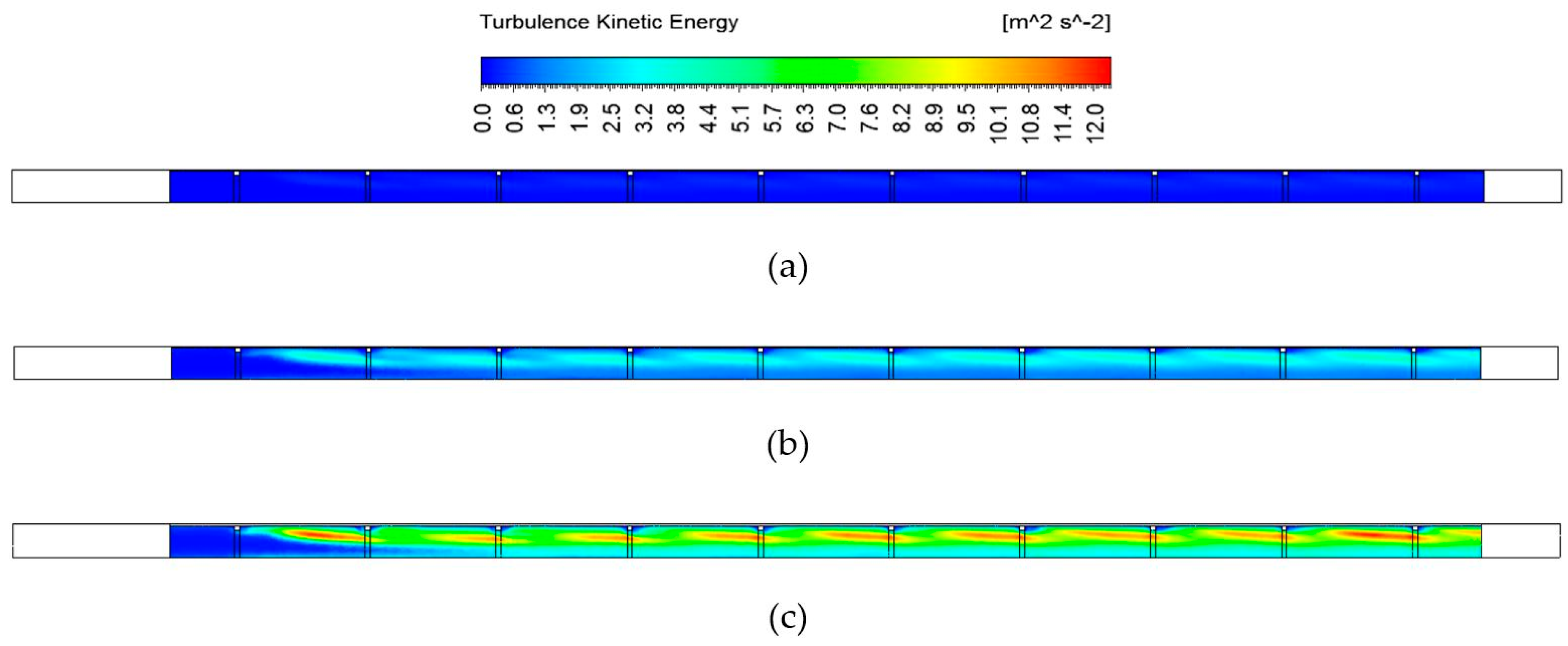
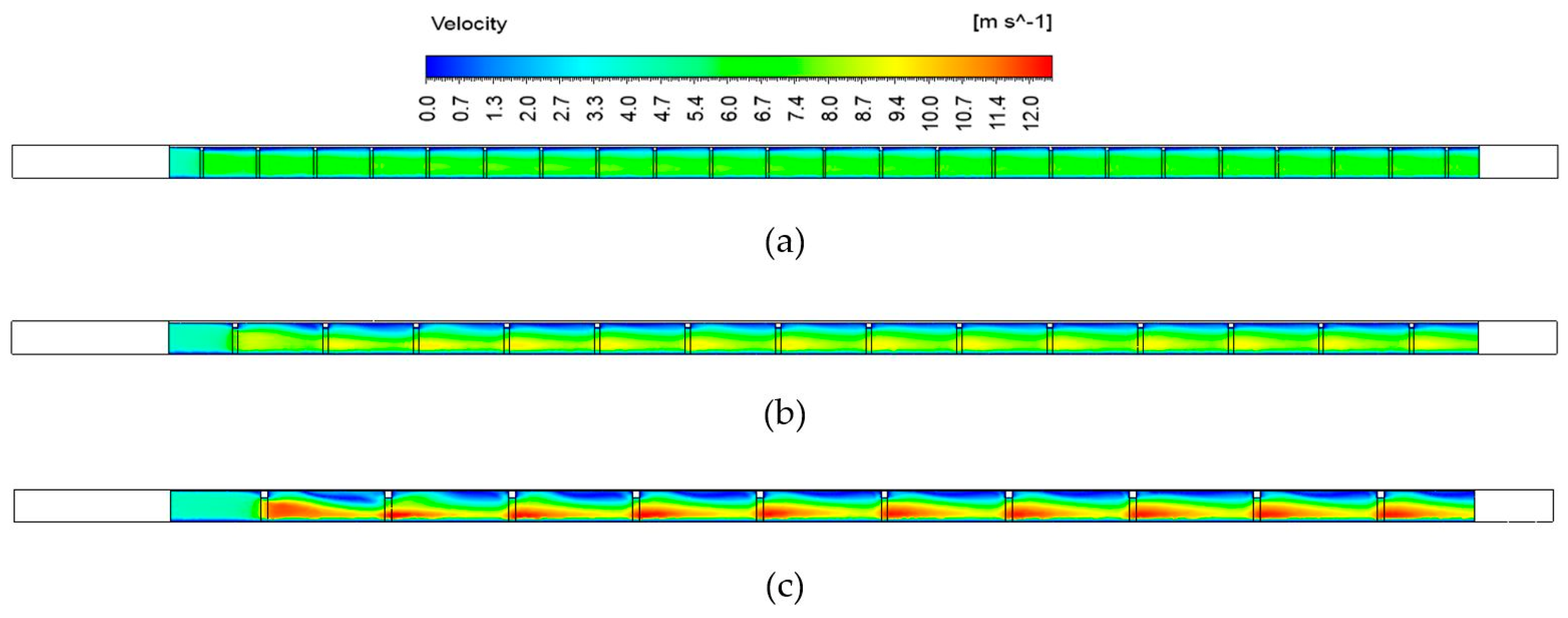
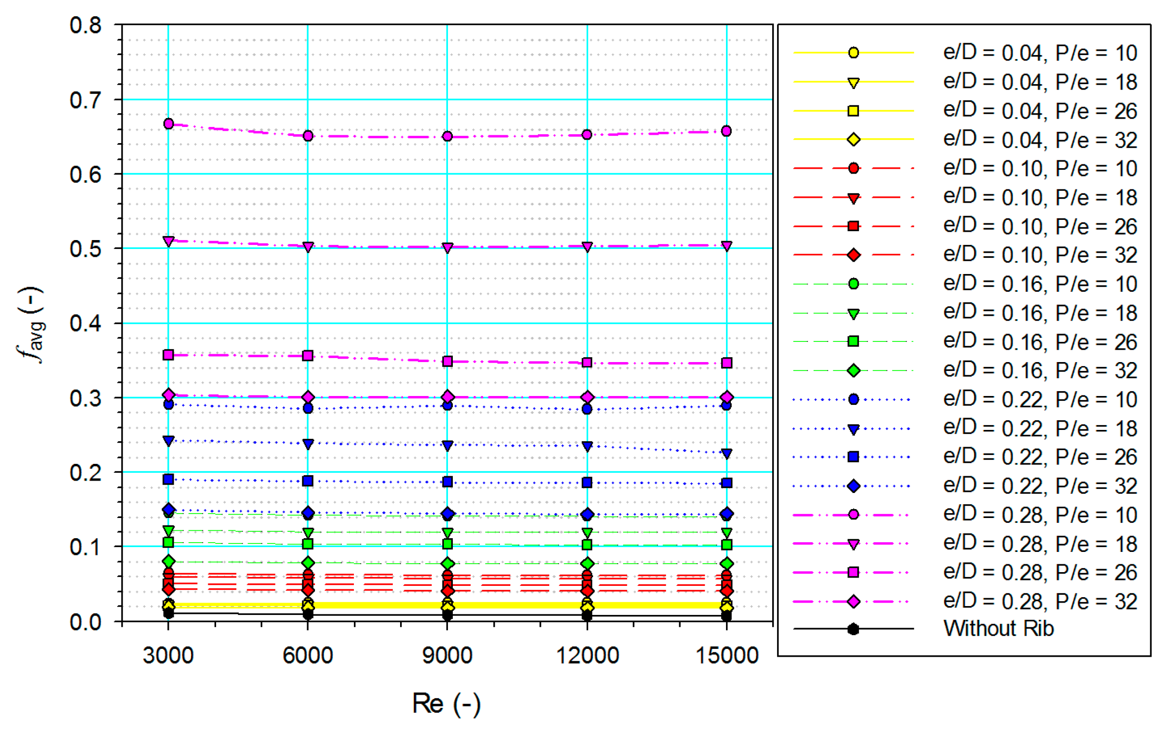
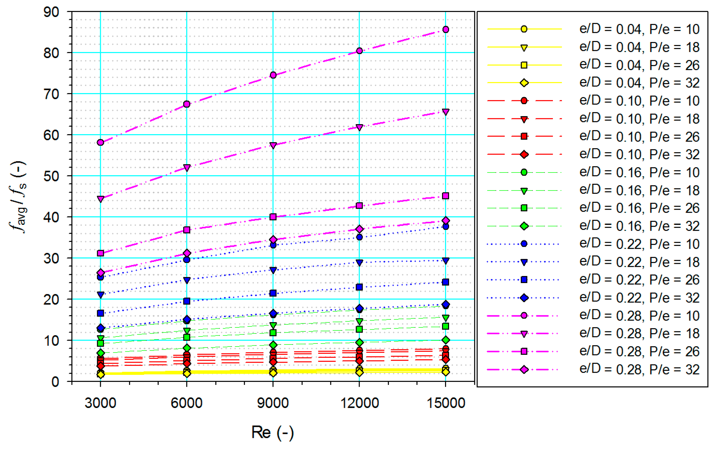
3.2. Flow Friction
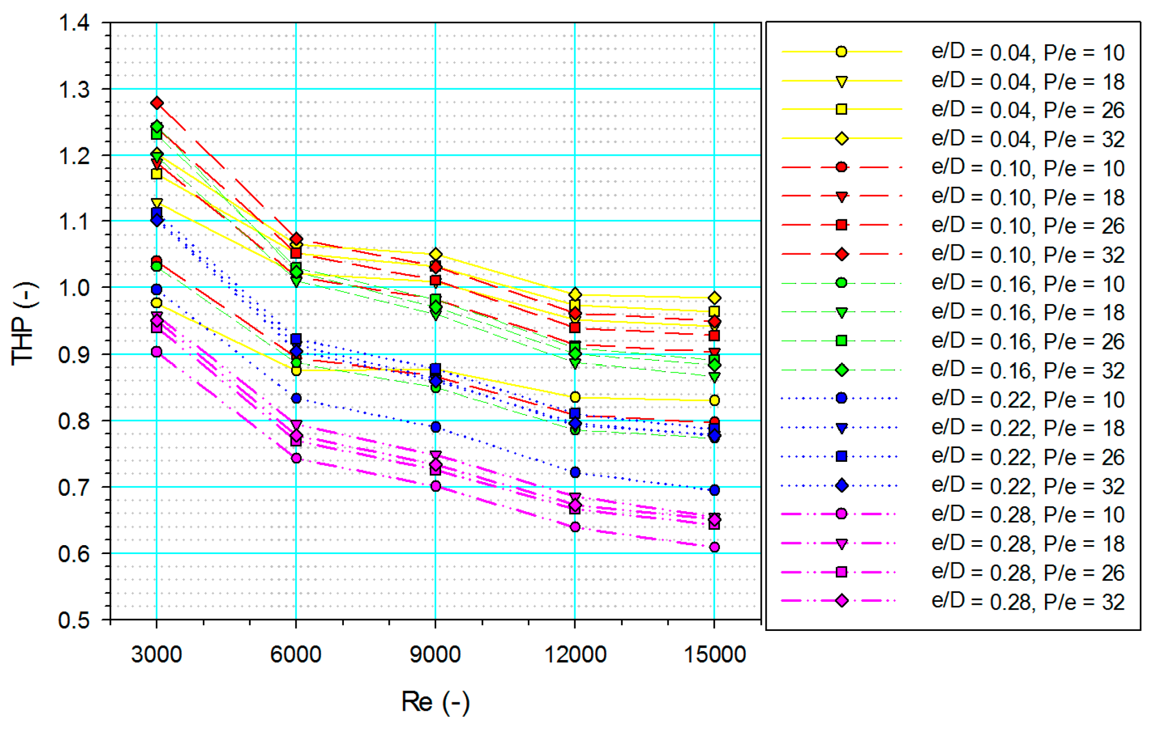
3.3. Thermo-hydraulic Performance
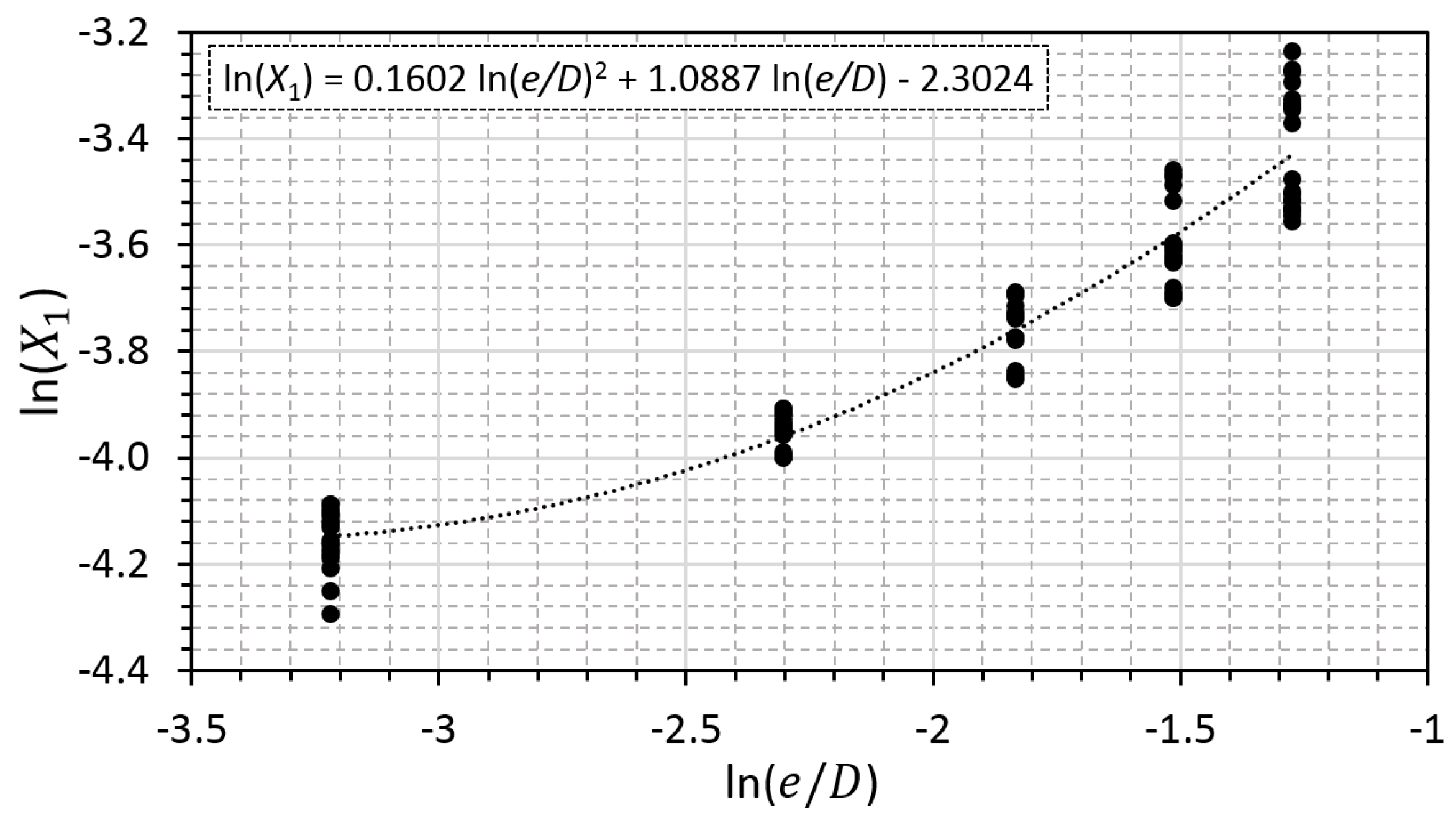
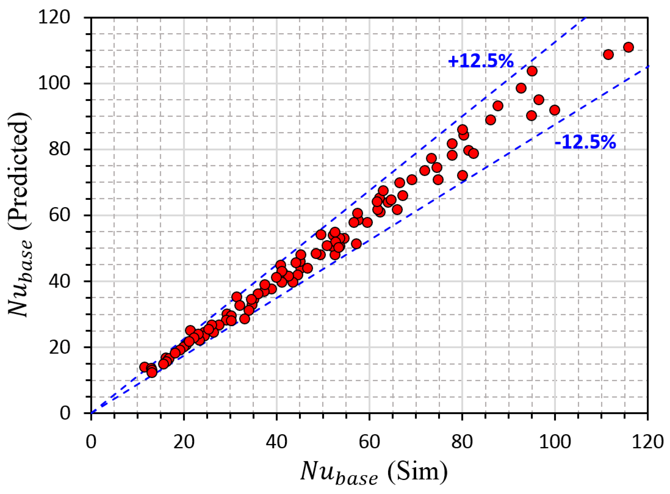
4. Development of Correlation
5. Conclusions
Author Contributions
Funding
Institutional Review Board Statement
Informed Consent Statement
Data Availability Statement
Conflicts of Interest
Nomenclature
| Area (m2) | |
| Hydraulic diameter (m) | |
| Convective heat transfer coefficient (W/m2·K) | |
| Length (m) | |
| Pressure drop (Pa) | |
| Heat transfer rate (W) | |
| Temperature (°C) | |
| Velocity (m/s) | |
| Thermal conductivity (W/m·K) | |
| Height of rectangular rib (m) | |
| Pitch of rectangular rib (m) | |
| Relative height of rectangular rib (-) | |
| Relative pitch of rectangular rib (-) | |
| Nusselt number (-) | |
| Reynolds number (-) | |
| Prandtl number (-) | |
| Friction factor (-) | |
| Friction factor for Gnielinski correlation (-) | |
| Greek symbol | |
| Density (kg/m3) | |
| Subscript | |
| Air channel | |
| Air | |
| Average | |
| Base surface of the fin | |
| Fin | |
| Smooth air channel | |
| Side surface of the fin | |
| Total | |
References
- Chamoli, S.; Lu, R.; Xu, D.; Yu, P. Thermal Performance Improvement of a Solar Air Heater Fitted with Winglet Vortex Generators. Sol. Energy 2018, 159, 966–983. [Google Scholar] [CrossRef]
- Markam, B.; Maiti, S. Artificial Enhancer for Small-Scale Solar Air Heater—A Comprehensive Review Aspect Ratio. Clean. Energy Syst. 2023, 4, 100046. [Google Scholar] [CrossRef]
- Singh Bisht, V.; Kumar Patil, A.; Gupta, A. Review and Performance Evaluation of Roughened Solar Air Heaters. Renew. Sustain. Energy Rev. 2018, 81, 954–977. [Google Scholar] [CrossRef]
- Yadav, A.S.; Bhagoria, J.L. A CFD (Computational Fluid Dynamics) Based Heat Transfer and Fluid Flow Analysis of a Solar Air Heater Provided with Circular Transverse Wire Rib Roughness on the Absorber Plate. Energy 2013, 55, 1127–1142. [Google Scholar] [CrossRef]
- Yadav, A.S.; Bhagoria, J.L. A Numerical Investigation of Square Sectioned Transverse Rib Roughened Solar Air Heater. Int. J. Therm. Sci. 2014, 79, 111–131. [Google Scholar] [CrossRef]
- Yadav, A.S.; Bhagoria, J.L. A CFD Based Thermo-Hydraulic Performance Analysis of an Artificially Roughened Solar Air Heater Having Equilateral Triangular Sectioned Rib Roughness on the Absorber Plate. Int. J. Heat Mass Transf. 2014, 70, 1016–1039. [Google Scholar] [CrossRef]
- Gawande, V.B.; Dhoble, A.S.; Zodpe, D.B.; Chamoli, S. Experimental and CFD Investigation of Convection Heat Transfer in Solar Air Heater with Reverse L-Shaped Ribs. Sol. Energy 2016, 131, 275–295. [Google Scholar] [CrossRef]
- Singh, A.; Singh, S. CFD Investigation on Roughness Pitch Variation in Non-Uniform Cross-Section Transverse Rib Roughness on Nusselt Number and Friction Factor Characteristics of Solar Air Heater Duct. Energy 2017, 128, 109–127. [Google Scholar] [CrossRef]
- Singh, I.; Vardhan, S.; Singh, S.; Singh, A. Experimental and CFD Analysis of Solar Air Heater Duct Roughened with Multiple Broken Transverse Ribs: A Comparative Study. Sol. Energy 2019, 188, 519–532. [Google Scholar] [CrossRef]
- Choi, H.U.; Choi, K.H. CFD Analysis on the Heat Transfer and Fluid Flow of Solar Air Heater Having Transverse Triangular Block at the Bottom of Air Duct. Energies 2020, 13, 1099. [Google Scholar] [CrossRef] [Green Version]
- Kumar, R.; Goel, V. Unconventional Solar Air Heater with Triangular Flow-Passage: A CFD Based Comparative Performance Assessment of Different Cross-Sectional Rib-Roughnesses. Renew. Energy 2021, 172, 1267–1278. [Google Scholar] [CrossRef]
- Alam, M.W.; Souayeh, B. Parametric CFD Thermal Performance Analysis of Full, Medium, Half and Short Length Dimple Solar Air Tube. Sustainability 2021, 13, 6462. [Google Scholar] [CrossRef]
- Haldar, A.; Varshney, L.; Verma, P. Effect of Roughness Parameters on Performance of Solar Air Heater Having Artificial Wavy Roughness Using CFD. Renew. Energy 2022, 184, 266–279. [Google Scholar] [CrossRef]
- Singh, V.P.; Jain, S.; Karn, A.; Kumar, A.; Dwivedi, G.; Meena, C.S.; Cozzolino, R. Mathematical Modeling of Efficiency Evaluation of Double-Pass Parallel Flow Solar Air Heater. Sustainability 2022, 14, 10535. [Google Scholar] [CrossRef]
- Fakoor Pakdaman, M.; Lashkari, A.; Basirat Tabrizi, H.; Hosseini, R. Performance Evaluation of a Natural-Convection Solar Air-Heater with a Rectangular-Finned Absorber Plate. Energy Convers. Manag. 2011, 52, 1215–1225. [Google Scholar] [CrossRef]
- Fudholi, A.; Sopian, K.; Ruslan, M.H.; Othman, M.Y. Performance and Cost Benefits Analysis of Double-Pass Solar Collector with and without Fins. Energy Convers. Manag. 2013, 76, 8–19. [Google Scholar] [CrossRef]
- Yang, M.; Yang, X.; Li, X.; Wang, Z.; Wang, P. Design and Optimization of a Solar Air Heater with Offset Strip Fin Absorber Plate. Appl. Energy 2014, 113, 1349–1362. [Google Scholar] [CrossRef]
- Priyam, A.; Chand, P. Thermal and Thermohydraulic Performance of Wavy Finned Absorber Solar Air Heater. Sol. Energy 2016, 130, 250–259. [Google Scholar] [CrossRef]
- Kabeel, A.E.; Hamed, M.H.; Omara, Z.M.; Kandeal, A.W. Influence of Fin Height on the Performance of a Glazed and Bladed Entrance Single-Pass Solar Air Heater. Sol. Energy 2018, 162, 410–419. [Google Scholar] [CrossRef]
- Kansara, R.; Pathak, M.; Patel, V.K. Performance Assessment of Flat-Plate Solar Collector with Internal Fins and Porous Media through an Integrated Approach of CFD and Experimentation. Int. J. Therm. Sci. 2021, 165, 106932. [Google Scholar] [CrossRef]
- Chand, S.; Chand, P.; Kumar Ghritlahre, H. Thermal Performance Enhancement of Solar Air Heater Using Louvered Fins Collector. Sol. Energy 2022, 239, 10–24. [Google Scholar] [CrossRef]
- Nagaraj, M.; Reddy, M.K.; Honnesara Sheshadri, A.K.; Karanth, K.V. Numerical Analysis of an Aerofoil Fin Integrated Double Pass Solar Air Heater for Thermal Performance Enhancement. Sustainability 2023, 15, 591. [Google Scholar] [CrossRef]
- Singh, S.; Singh, B.; Hans, V.S.; Gill, R.S. CFD (Computational Fluid Dynamics) Investigation on Nusselt Number and Friction Factor of Solar Air Heater Duct Roughened with Non-Uniform Cross-Section Transverse Rib. Energy 2015, 84, 509–517. [Google Scholar] [CrossRef]
- Singh, I.; Singh, S. CFD Analysis of Solar Air Heater Duct Having Square Wave Profiled Transverse Ribs as Roughness Elements. Sol. Energy 2018, 162, 442–453. [Google Scholar] [CrossRef]
- Kumar, R.; Kumar, A.; Goel, V. Performance Improvement and Development of Correlation for Friction Factor and Heat Transfer Using Computational Fluid Dynamics for Ribbed Triangular Duct Solar Air Heater. Renew. Energy 2019, 131, 788–799. [Google Scholar] [CrossRef]
- Kumar, A.; Saini, R.P.; Saini, J.S. Experimental Investigation on Heat Transfer and Fluid Flow Characteristics of Air Flow in a Rectangular Duct with Multi V-Shaped Rib with Gap Roughness on the Heated Plate. Sol. Energy 2012, 86, 1733–1749. [Google Scholar] [CrossRef]
- Nidhul, K.; Yadav, A.K.; Anish, S.; Arunachala, U.C. Efficient Design of an Artificially Roughened Solar Air Heater with Semi-Cylindrical Side Walls: CFD and Exergy Analysis. Sol. Energy 2020, 207, 289–304. [Google Scholar] [CrossRef]
- Patel, S.S.; Lanjewar, A. Experimental Investigation of Solar Air Heater Duct with Discrete V-Rib Integrated with Staggered Elements. Int. J. Sustain. Eng. 2021, 14, 162–171. [Google Scholar] [CrossRef]
- Kumar, S.; Verma, S.K. Heat Transfer and Fluid Flow Analysis of Sinusoidal Protrusion Rib in Solar Air Heater. Int. J. Therm. Sci. 2022, 172, 107323. [Google Scholar] [CrossRef]
- Chaube, A.; Sahoo, P.K.; Solanki, S.C. Analysis of Heat Transfer Augmentation and Flow Characteristics Due to Rib Roughness over Absorber Plate of a Solar Air Heater. Renew. Energy 2006, 31, 317–331. [Google Scholar] [CrossRef]
- Alam, T.; Kim, M.H. Heat Transfer Enhancement in Solar Air Heater Duct with Conical Protrusion Roughness Ribs. Appl. Therm. Eng. 2017, 126, 458–469. [Google Scholar] [CrossRef]
- Cengel, Y.A.; Ghajar, A.J. Heat and Mass Transfer: Fundamentals & Applications, 4th ed.; McGraw-Hill: New York, NY, USA, 2011. [Google Scholar]
- Webb, R.L.; Eckert, E.R.G. Application of Rough Surfaces to Heat Exchanger Design. Int. J. Heat Mass Transf. 1972, 15, 1647–1658. [Google Scholar] [CrossRef]
- Gupta, A.D.; Varshney, L. Performance Prediction for Solar Air Heater Having Rectangular Sectioned Tapered Rib Roughness Using CFD. Therm. Sci. Eng. Prog. 2017, 4, 122–132. [Google Scholar] [CrossRef]
- Karwa, R.; Chauhan, K. Performance Evaluation of Solar Air Heaters Having V-down Discrete Rib Roughness on the Absorber Plate. Energy 2010, 35, 398–409. [Google Scholar] [CrossRef]
- Matheswaran, M.M.; Arjunan, T.V.; Somasundaram, D. Analytical Investigation of Solar Air Heater with Jet Impingement Using Energy and Exergy Analysis. Sol. Energy 2018, 161, 25–37. [Google Scholar] [CrossRef]
- Choi, H.; Choi, K. Parametric Study of a Novel Air-Based Photovoltaic-Thermal Collector with a Transverse Triangular-Shaped Block. Renew. Energy 2022, 201, 96–110. [Google Scholar] [CrossRef]
- Singh, V.P.; Jain, S.; Karn, A.; Kumar, A.; Dwivedi, G.; Meena, C.S.; Dutt, N.; Ghosh, A. Recent Developments and Advancements in Solar Air Heaters: A Detailed Review. Sustainability 2022, 14, 12149. [Google Scholar] [CrossRef]


| Parameter | Value | |
|---|---|---|
| Air channel | Height (mm), | 24 |
| Width (mm), | 12 | |
| Fin | Height (mm), | 25 |
| Width (mm), | 12.5 | |
| Thickness (mm) | 1 | |
| Rectangular rib | Relative height (−), | 0.04, 0.1, 0.16, 0.22, 0.28 |
| Relative pitch (−), | 10, 18, 26, 34 | |
| Reynolds number (−), | 3000, 6000, 9000, 12,000, 15,000 | |
| Boundary | Conditions |
|---|---|
| Inlet velocity (m/s) | 1.83–9.13 |
| Reynolds number (−) | 3000–15,000 |
| Outlet pressure (Pa) | 101,325 |
| Top surface of the fin (W/m2) | 800 |
| Side surface of the solution domain | Symmetric |
| Other walls | Adiabatic |
| Number of Cell | (-) | (%) | (-) | (%) | (-) | Change in (-) |
|---|---|---|---|---|---|---|
| 1,167,142 | 33.687 | - | 39.577 | - | 0.0262 | - |
| 3,690,883 | 32.965 | 2.192 | 37.007 | 6.945 | 0.0247 | 5.823 |
| 4,691,223 | 31.933 | 3.232 | 37.544 | 1.432 | 0.0248 | 0.046 |
| 5,998,181 | 32.377 | 1.373 | 38.030 | 1.277 | 0.0251 | 1.355 |
| 7,296,861 | 32.382 | 0.014 | 38.299 | 0.703 | 0.0252 | 0.498 |
Disclaimer/Publisher’s Note: The statements, opinions and data contained in all publications are solely those of the individual author(s) and contributor(s) and not of MDPI and/or the editor(s). MDPI and/or the editor(s) disclaim responsibility for any injury to people or property resulting from any ideas, methods, instructions or products referred to in the content. |
© 2023 by the authors. Licensee MDPI, Basel, Switzerland. This article is an open access article distributed under the terms and conditions of the Creative Commons Attribution (CC BY) license (https://creativecommons.org/licenses/by/4.0/).
Share and Cite
Choi, H.-U.; Moon, K.-A.; Kim, S.-B.; Choi, K.-H. CFD Analysis of the Heat Transfer and Fluid Flow Characteristics Using the Rectangular Rib Attached to the Fin Surface in a Solar Air Heater. Sustainability 2023, 15, 5382. https://doi.org/10.3390/su15065382
Choi H-U, Moon K-A, Kim S-B, Choi K-H. CFD Analysis of the Heat Transfer and Fluid Flow Characteristics Using the Rectangular Rib Attached to the Fin Surface in a Solar Air Heater. Sustainability. 2023; 15(6):5382. https://doi.org/10.3390/su15065382
Chicago/Turabian StyleChoi, Hwi-Ung, Kwang-Am Moon, Seong-Bhin Kim, and Kwang-Hwan Choi. 2023. "CFD Analysis of the Heat Transfer and Fluid Flow Characteristics Using the Rectangular Rib Attached to the Fin Surface in a Solar Air Heater" Sustainability 15, no. 6: 5382. https://doi.org/10.3390/su15065382
APA StyleChoi, H.-U., Moon, K.-A., Kim, S.-B., & Choi, K.-H. (2023). CFD Analysis of the Heat Transfer and Fluid Flow Characteristics Using the Rectangular Rib Attached to the Fin Surface in a Solar Air Heater. Sustainability, 15(6), 5382. https://doi.org/10.3390/su15065382