Article

Novel Sustainable Masonry from Ancient Construction Techniques by Reusing Waste Modern Tiles

Department of Civil and Building Engineering and Architecture (DICEA), Polytechnic University of Marche, 60131 Ancona, Italy
*
Author to whom correspondence should be addressed.
Sustainability 2023, 15(6), 5385; https://doi.org/10.3390/su15065385
Submission received: 9 February 2023 / Revised: 7 March 2023 / Accepted: 9 March 2023 / Published: 17 March 2023

Abstract

:
The recycling and reuse of wastes, especially Construction Waste (CW), is a fundamental way for sustainability. The act of reusing is not a modern practice; as early as in Ancient Rome and even more during the Middle Ages, materials were already being taken from existing buildings in order to reuse them in different ways. Starting from these general considerations and taking inspiration from specific construction techniques found in some Roman and Romanesque masonries made by unbroken tiles and tile fragments, two novel sustainable masonry constructive techniques are proposed here. They are composed of modern U-shaped tiles and their fragments so as to use CW. Monotonic and cyclic compression tests were performed so as to determine their main mechanical characteristics, such as compressive strength, Young’s modulus, and failure mode, and a first attempt at establishing their possible use in the construction sector is sought. A comparison with the literature values from other constructive techniques with similar values was also performed. It results that both the wall typologies showed satisfactory mechanical properties (i.e., compressive strengths are in the range of 1.28 ÷ 2.27 MPa), provided that their use is restricted for constructions of moderate dimensions.

1. Introduction

Reusing materials is a possible way for sustainability, considering that the reduction of non-renewable resources is a constant concern to the conservation of the environment. In recent years, environmental sustainability has required a reduction in the exploitation of non-renewable resources and a progressive increase in waste valorisation in various areas.
Thus, the recycling and reusing of wastes, especially in the construction industry, is a fundamental way towards sustainability [1]. According to Directive 2008/98/EC of the European Parliament [2], the construction industry is responsible for 50% of the consumption of natural resources, and the Construction Demolition Waste (CDW) accounts for approximately 25–30% of all waste generated in Europe; most of it ends up in landfills [3]. CDW commonly refers to various solid wastes from various civil engineering applications, such as concrete, tile, ceramics, brick, wood, glass, plastic, asphalt blends, soils, and metals [1,4,5,6]. The portion of CDW relating to masonry for EU Member States (except Estonia and Finland) is from a minimum of 8% to a maximum of 54% [3].
Some recent studies suggest the possibility of using CDW aggregates, for example, for the development of concrete [7,8,9], rendering mortars [10], or gypsum-based mixture containing recycled roofing tile powder [11]. Materials such as steel, glass, and aluminium are reused, especially in developing countries [12], as well as organic (polymeric) construction materials [13]. For example, recycled and locally available glass has been tested as component of a thermally efficient fibre-based eco-friendly brick [14]. Using Recycled Brick Aggregate (RBA) that may come from building construction and ceramic industry wastes is also an eco-friendly solution for making sustainable materials. The RBA aggregate is obtained through crushing, and brick particles can be coarse or fine according to the requirements [15]. Few studies that try to propose the reuse of ceramic materials from CDW without crushing them in particles, i.e., reusing them just fragmented, are present in the literature, even if this makes it even more sustainable and reduces the impact on the environment, avoiding the reworking process of waste materials. In fact, recovering ceramic waste and reusing or recycling them in construction field are complex issues, which require and impose microstructural and structural investigations as a first step in the selection of the materials and the area of their uses [16].
The act of reusing is not, in fact, a modern practice: the ancient Romans [17] were already accustomed to doing so; even more during the Middle Ages [18], materials were taken from existing structures to be used in different ways, thus pre-existing buildings were often exploited to build new construction, both for civil and religious purposes [19]. During medieval times, the practice of building stripping and the reuse of ancient material had economic reasons, an aspect that was of fundamental importance in the case of masonry structures, but they could also have symbolic or political motives [20]. The topic of reuse during Middle Ages seems to have two different forms: one referred to the “physical” reuse of ancient material, which almost always involved the destruction of the original structures; and the other aimed at the ideal recovery of a technique from the past and Roman classical culture [21].
In this way, peculiar past construction techniques that reuse materials [22] could suggest new sustainable construction methods that could be used for specific situations, but they need to be mechanically tested. However, to the best of the authors’ knowledge, no research has been conducted to propose using ancient construction techniques nowadays again by reusing modern ceramic construction waste (i.e., tiles).
Starting from these considerations and taking inspiration from specific construction techniques found in some Roman and Romanesque masonries made by unbroken tiles and tile fragments, two novel sustainable technological-constructive systems are proposed and mechanically characterized here so as to have a first attempt at their possible use, especially, in the context of developing countries in which the resources are limited [23].
In particular, the first one is made entirely from waste of tiles, while the second is made from a mix of intact tiles and waste of tiles. The first technique is surely more sustainable because it only uses waste of tiles. However, the second typology was tested to understand if the use of intact tiles, even if less sustainable, could lead to better mechanical behaviour. The same mortar with low mechanical characteristics was used for both typologies. It takes inspiration from the poor mortar used in the ancient construction techniques taken as references. This allows for having a more sustainable and cheaper mortar due to its very low lime and sand content as well as using (recycled) gravel.
The possible use of these two techniques as construction material has been verified by assessing the main mechanical properties—that is, compression strength, failure modes, and elastic modulus, as requested by several codes—through monotonic and cyclic tests usually used for testing masonry wall specimens [22,24,25,26,27]. This is surely the first step for validating them; otherwise, no other further test would make sense if this test went wrong.
The results were compared to masonry with similar reference literature values.
Then, compression strengths were used for assessing if the two novel tested masonry could withstand loads for at last simple, small, and regular buildings.

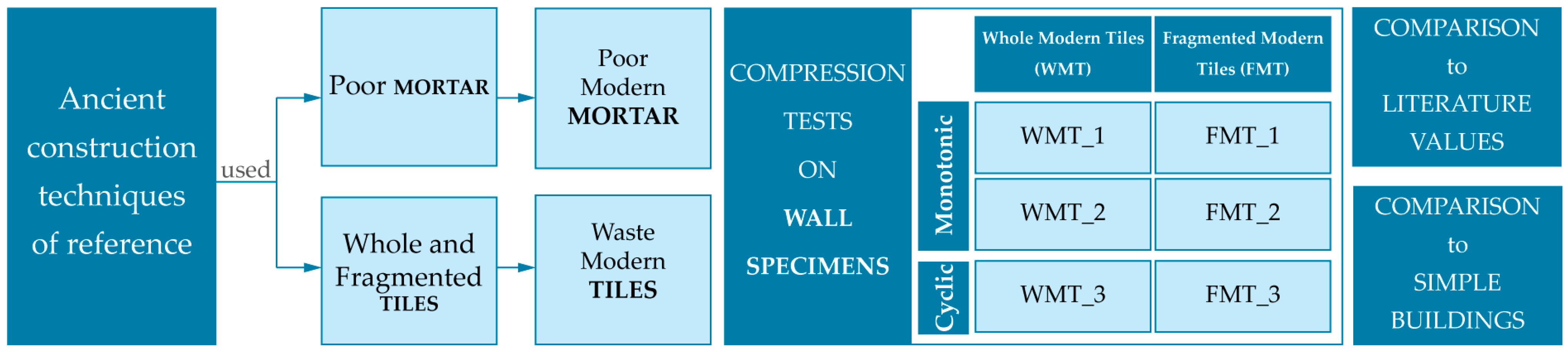
2. Materials and Methods

Taking inspiration from ancient construction techniques of reference that reused fragments of tiles and mortar, this work tries to update these construction techniques by using current CDW and mechanically testing them. The first step was to test the materials used: a poor modern mortar and waste modern tiles. Then, six wall specimens were made and assessed by monotonic and cyclic compression tests following UNI EN 1052-1 [28] and the literature [22,24,25,26,27].
After some consideration about results, a comparison with reference literature values and verification for simple buildings were made. Figure 1 shows the flow chart of the method used.

2.1. Technological-Constructive Systems of Tiles Masonries

The Romanesque masonries we also refer to are those found at the S. Maria in Portuno Church (Corinaldo (AN), Marche, Italy), less than 10 km from the domus of Coiedii. These represent a good example of the reuse of Roman tile (likely just those from the domus of Coiedii) and brick fragments to build masonry walls in the High Middle Age (10th–11th centuries AD) [16,17], presenting a similar construction technique but using tile fragments as the first layer instead of unbroken tiles (Figure 2).
Starting from such constructive examples, two types of wall specimens have been reproduced by using modern materials and then characterized mechanically:
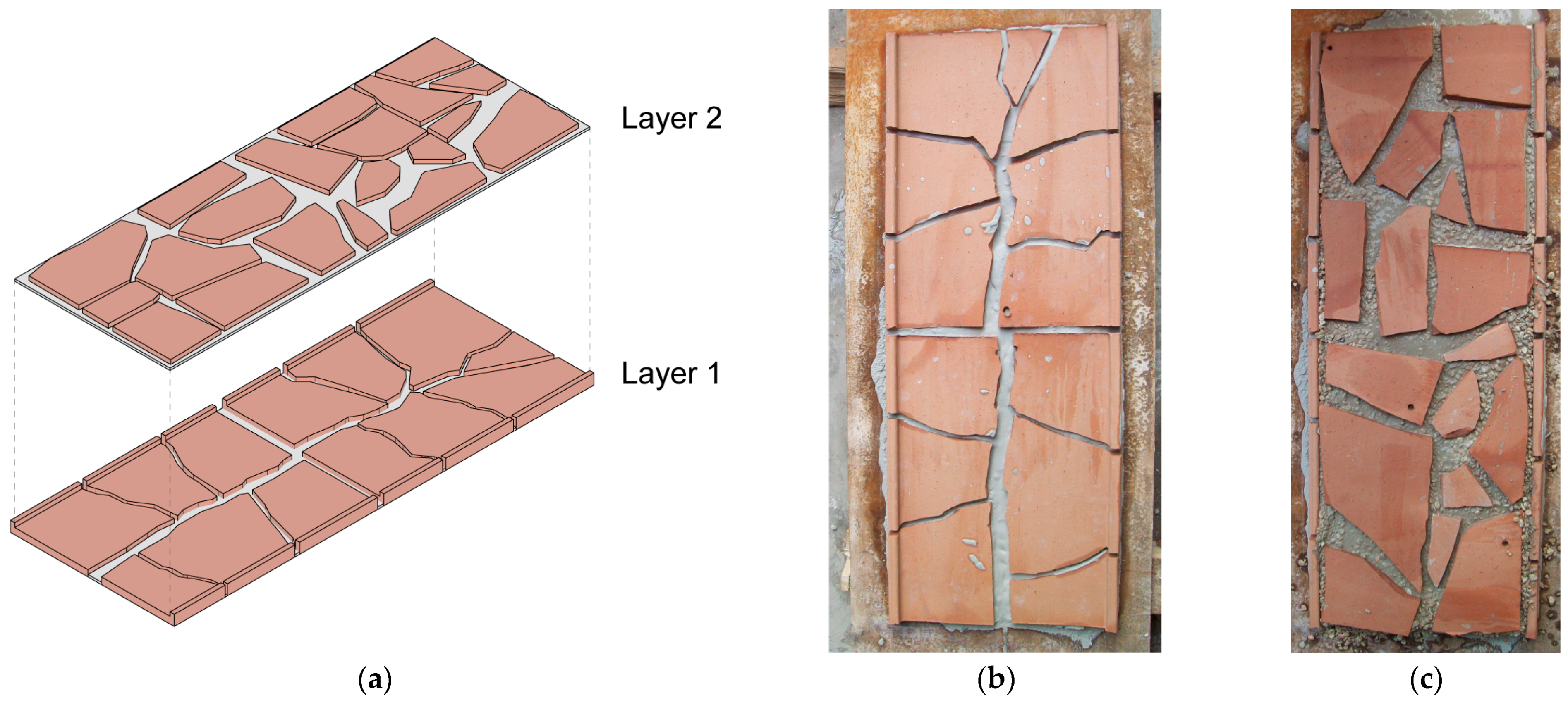
  • FMT (Fragmented Modern Tiles): in which the first layer is made by tile fragments placed with their raised edge towards the outside, and the second one fills the internal U-gap and is always made by tile fragments (Figure 2). This type is inspired by the previous Romanesque walls Three walls of the nominal size 1.00 × 0.39 × 0.78 m3 (Figure 2b,c) were made by this construction technique. This type of masonry requires additional skills, and it is a little bit more time-consuming than the first one.
  • WMT (Whole Modern Tiles): in which the first layer is made by unbroken tiles placed with their raised edges towards the outside, and the second one fills the internal U-gap and is made by tile fragments (Figure 3). This type is inspired by the previous Roman walls. Three walls of the nominal size 0.95 × 0.35 × 0.80 m3 were made by this construction technique (Figure 3b,c).
To regularize the upper face of the wall specimens, a layer of mortar was made on the top of the walls. To avoid the absorption of water from the mortar, the tiles were wetted before the manufacturing of wall specimens. Moreover, to contain the evaporation, all the surfaces of the specimens have been wetted for the first hours of the drying process.

2.2. The Mortar

Taking inspiration from the two previous ancient construction techniques, a poor mortar with a low lime content was used in this work too (Table 1). This allows for having a more sustainable and cheaper mortar due to its very low lime and sand content as well as using (recycled) gravel where resources are limited (i.e., developing countries) too [12].
The mortar was made by using the following as constituents: gravel, coarse sand, fine sand, and natural hydraulic lime. Grain size and mixture proportion are defined in Table 1. Such gravel was used, following Roman and Romanesque constructive techniques, for having a robust skeleton fill the large voids between the tile fragments, reducing the shrinkage. This may also simulate coarse sizing waste to be used. Even if we still use the term “mortar,” it is a sort of “conglomerate” (even if the binder is in a very low content) because of the presence of gravel in the composition of this material.
The water content was determined after several attempts to obtain a good workability and an optimal consistency of the mixture obtained.
Six cubic specimens of the size 15 × 15 × 15 cm3 were tested to characterize the mechanical behaviour of the mortar according to UNI EN 12390-3 (2003) [29]. Cardboard was used to compensate specimen irregularities on the upper and lower faces of the specimen so as to allow a uniform distribution of the load by avoiding local tension concentrations during compression tests.
The apparatus used for compression tests was a “Galdabini” universal model of first class with an end scale of 400 kN and a 1% error. The compression tests were carried out by displacement control (equal to about 0.05 mm/s). The elastic modulus of each specimen was determined based on the slope of the trendline that represents the best approximation (considering R2 always over 0.99) of the initial linear part of the stress–strain diagram.
The average compressive strength was equal to 0.34 MPa (with a standard deviation of 0.04 MPa), and the average of the elastic modulus was equal to 38 MPa (with a standard deviation of 10 MPa). These low values seem to be caused by the low lime’s content and by the coarse dimensional distribution (Table 1). All six specimens showed an identifiable failure mode with pyramidal shapes with diagonal cracks, typical for concrete specimens (Figure 4).

2.3. The Tiles

Modern tiles of size 46.0 × 35.0 × 2.5 cm, considering their raised edges of size 1.0 × 1.0 cm and produced by the factory “Cotto San Michele”, Mondavio (PU), Italy, were used to build the wall specimens.
Compression tests on 6 tile specimens were performed by displacement control (displacement rate was equal to about 0.02 mm/s) with the same apparatus used for the mortar specimens, according to UNI EN 772-1 (2015) [30]. The elastic modulus of each specimen was defined through the slope of the trendline that is the best approximation (considering R2 always over 0.99) of the initial linear part of the stress–strain diagram. Specimens were conditioned using procedure a) of conditioning to the oven dry condition before testing, which consists of drying the specimens at 105 ± 5 °C at a constant mass. Constant mass is reached if, during the drying process in subsequent weighing with not less than a 24 h interval, the loss in mass between two weighings is less than 0.2% of the total mass. It is then necessary to allow the specimens to cool to ambient temperature before testing.
UNI EN 772-1 [30] also specifies that the test specimens must be composed of two piled tile elements, without mortar between them, if each single element has its height less than 40 mm or the ratio between its height and its width is less than 0.4. Since the single tile element is 15 mm high, each tested specimen consisted of two piled elements, each 0.060 × 0.060 × 0.015 m3, obtained by cutting the tiles.
The average compressive strength was equal to 88.2 MPa (with a standard deviation of 15.4 MPa), and the average elastic modulus was equal to 1112 MPa (with a standard deviation of 213 MPa). In order to take into account the aspect ratio and the conditioning regime used, the average normalized compressive strength (fb) of the tile specimens was also determined. The compressive strength is first transformed to an equal compressive strength related to the air-dry conditioning regime. The value used as the multiplier for this case was 0,8 because the specimens were conditioned using the oven dry condition. In order to obtain the normalised compressive strength, it is necessary to multiply the air-dry compressive strength by a shape factor d, which depends on the width and height of the specimens (d = 0.73 in our case). The average normalized compressive strength fb was equal to 51.5 MPa, according to [31], which is slightly higher than the compressive strength of brick elements used for modern masonries that should be within 2 and 40 MPa.

2.4. Compression Tests on Wall Specimens
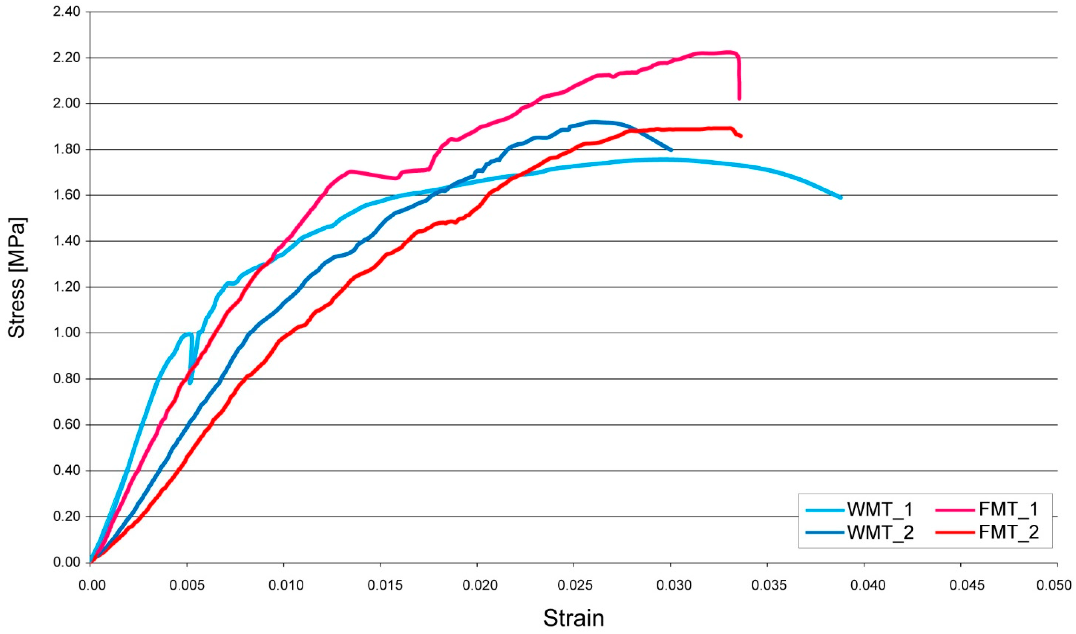
Monotonic compression tests were performed on two walls for each type after at least one month of drying process, following UNI EN 1052-1 [28] and the literature [22,24,25,26,27]. As shown in Figure 5, four vertical transducers were used to measure vertical displacements. They were positioned on the top metal plate. In this way, by placing the four transducers close to the four vertices of the upper metal plate, the presence (or absence) of bending during the compression test was assessed, considering both directions. The stress–strain curve was obtained taking into account the average compression stress (the total vertical load divided by the nominal area) and the equivalent average value of the vertical strains coming from these four measuring points, after verifying that no bending happened. A transducer was also installed to assess the possible horizontal displacements (sliding) of the top metal plate during each compression test, but the slipping of the upper plate never took place.
To give vertical load, four hydraulic jacks were arranged, with a maximum load of 500 kN each and pressurized all at the same value, that could not be managed separately in case of bending.
The elastic modulus of each wall specimen was determined, as it has been determined with the Young modulus of tiles, by the slope of the trendline which represents the best approximation of the initial linear part of the stress–strain diagram (considering R2 always over 0.99).
WMT_3 and FMT_3 were tested by cyclic compression test [22,24,25,26,27] after the same drying process, arrangement, and assessment of the previous monotonic tests. Even in this case, the bending as well as the slipping of the upper plate never happened. Considering the maximum value of the compressive load obtained after the monotonic compression tests, four loading steps were performed at one-fourth, one-half, and three-fourths of this value, and the last loading step until the failure of the specimen. The elastic modulus of each specimen was determined by the slope of the trendline which represents the best approximation (considering R2 always over 0.97) of the initial linear part of the stress–strain diagram.
The stiffness modification of the specimens was estimated by the scalar compaction parameter (Equation (1)):
c n = 1 ( E i E a )
where E i is the initial elastic modulus, and E a is the elastic modulus of the actual load step.

3. Results

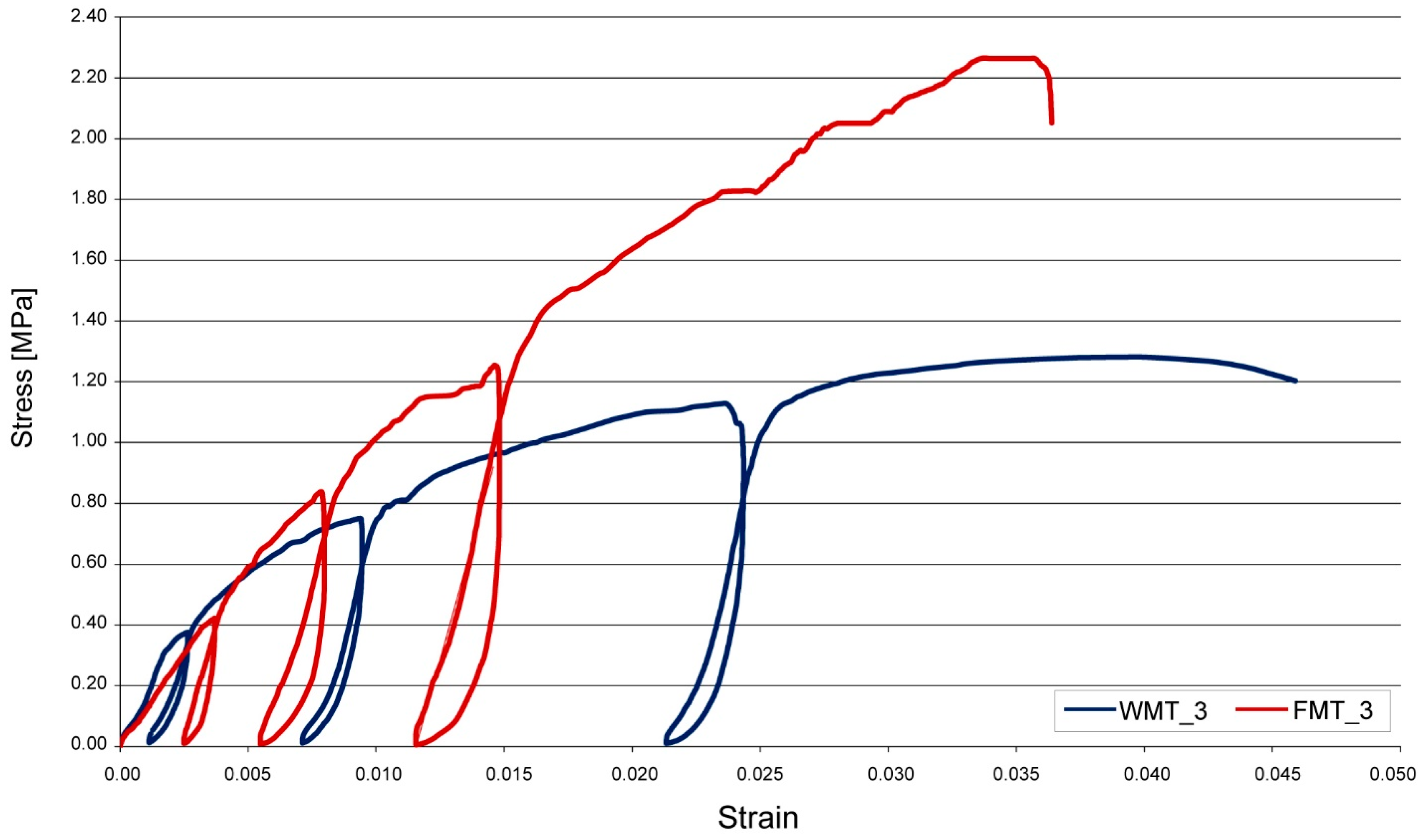
3.1. Monotonic and Cyclic Tests

The stress–strain curves of monotonic test are presented in Figure 6, while those of the cyclic test are given in Figure 7. Table 2 reports the main results of the tests.
The first cracks in WMT specimens always appeared earlier than the first cracks in FMT specimens (Table 2).
However, they were always vertical and placed on the raised edge of the tiles and appeared on the larger sides of each specimen.
The WMT specimens have a confining effect thanks to the raised edge of the tiles. In monotonic tests, this effect can be seen in the mean elastic modulus of WMT specimens, which is 18% higher than the mean elastic modulus of FMT specimens, even if these values are a bit scattered as commonly happened for the Young modulus.
At a certain load threshold, the tiles break into two or more parts (see forthcoming Figure 8c–h and Figure 9b), likely due to local stress concentrations (caused by even the low quality of the mortar). This threshold is at about 1 MPa in Figure 6 and is clearly recognizable in the WMT_1 specimen (there is a localized lack of load bearing capacity) and, to a minor extent, also in the WMT_2 specimen (there is an “instantaneous” change in the slope of the curve).
By further increasing load, both WMT and FMT specimens are practically the same, so the same subsequent mechanical behaviour, including compressive strength, is expected. In fact, in monotonic tests, the mean compressive strength of FMT specimens is 2.06 MPa, while that of the WMT specimens is 1.84 MPa, which are very close and allow to conclude that both construction techniques reach low values of compressive strength, close to about 2 MPa. To further confirm the previous understanding, we also note that the mean ultimate strain is approximately the same.
These low mechanical values seem to be strictly related to the peculiar construction technique and the poor quality of the mortar. In fact, the vertical deformability of the tested specimens is relevant. This seems to be due to the mortar with low binder content, which is very ductile and can present voids, when laying, because of the particle size distribution of its constituents. Furthermore, the nonhomogeneous distribution of the tile fragments standing on each unbroken tile as well as the presence of gravel into the mortar may have produced local stress concentrations during the compression tests, as already previously underlined.
In cyclic tests (Figure 7), it is necessary to remark that the WMT_3 specimen behaved poorly, with the lowest slope and the lowest compressive strength (1.28 MPa) with respect to all the other specimens. This is probably due to the fact that it had the earliest first cracks (0.38 MPa) during the first loading step. This is not fully surprising, considering the nonhomogeneous distribution of the tile fragments standing on each whole tile as well as the presence of gravel in the mortar that could have triggered local stress concentrations.
In cyclic tests, the increase in of the elastic modulus, caused by the first loading step, can be related to the compaction of the wall specimen. All values of the scalar compaction parameter ( c n ), shown in Table 2, are positive, because all the elastic moduli are higher than the initial elastic modulus ( E i ), but the elastic modulus did not always increase at each step.
In this way, it can be useful make a comparison between the elastic modulus of the previous load step E ( a 1 ) with the elastic modulus of the current load step E a , too, so as to calculate Equation (2):
c n 1 = 1 ( E ( a 1 ) E a )
When the relative scalar compaction parameters c n 1 (shown in Table 2) are negative, it means that the elastic modulus decreased (so degraded): this is the case of EF-3.3.
In WMT_3, the elastic modulus always increased in the first three loading steps, so the specimen became more compact. Instead, FMT_3 became more compact in the first two loading steps and in the fourth one but degraded in the third one: this probably happened because in the third loading step there was an expulsion of a tile. In this case, the degradation happened when the elastic modulus greatly increased (more than 100%) respective to the first value.
In the Italian technical standard [32], the values of compressive strength of the tested specimens are compatible with those related to masonries made by tuff blocks (1.40 ÷ 2.20 MPa) and irregular stone masonries (1.00 ÷ 2.00 MPa). In contrast, their elastic moduli are between 900 ÷ 1260 MPa and 690 ÷ 1050 MPa, respectively [32], so they are higher than those of the specimens.
Nevertheless, as already demonstrated in past research [14,22], in some cases, mechanical properties of historical masonries can be different from those shown in technical standards.
In addition, these values of compressive strength are similar to those of poor construction materials earth [33] that was used since prehistoric times and still used nowadays in both developed and developing countries [34]. For example, rammed earth walls show a comparable compressive strength of 1.69 ÷ 2.35 MPa [35]. Instead, cob walls show even lower values 1.05 ÷ 1.17 MPa [34], as well as adobe walls 0.77 ÷ 1.2 MPa [36] (Table 3).
This seems to confirm that both of the novel tested construction techniques could be used as sustainable alternatives to such poor ones, especially the FMT type because it totally uses tile wastes. This could be true only if we consider the nonconcurrence of landfill disposal of tile wastes, which is considered as a benefit during the calculation of Ambiental impacts [37].
The low values of the resistance, anyway, do not limit the use of this material for regular and short constructions (such as farm sheds) or small buildings, where the operating conditions are usually between 0.1 ÷ 0.2 MPa, depending on the dimensions and construction materials.
In this way, by considering the Italian technical standard [31], it is possible to verify (Equation (3)) simple buildings by means of:
σ = N 0.65   A f k γ M
where:
  • N is the total vertical load at the base of each level of the building, corresponding to the sum of the permanent and variable loads (combination coefficients are equal to 1);
  • A is the total area of load-bearing walls of the same floor;
  • f k is the characteristic compressive strength of the masonry;
  • γ M is the partial safety factor of the compressive strength of the masonry, equal to 4.2.
For example, we can consider a two-storey building with a rectangular plan of 10.0 × 8.0 m, considering the outer edge of the perimeter, and a wall thickness of 0.8 m, made by four perimetral walls and one inside in the middle, on which the wooden slabs rest on (Table 4). By assuming [31]:
  • That all the limitations about the openings of the masonry and the dimensions of seismic-resistant walls are respected;
  • The lowest compressive strength (1.28 MPa = 1280 kN/m2) among all the tested specimens, obtained for WMT_3, even if this sample manifested clear problems, we considered the worst condition.
  • The maximum admissible floor height (3.5 m) and an appropriate overload for wooden roof slab and wooden inter-floor slab (2.0 kN/m2) for such simple buildings.
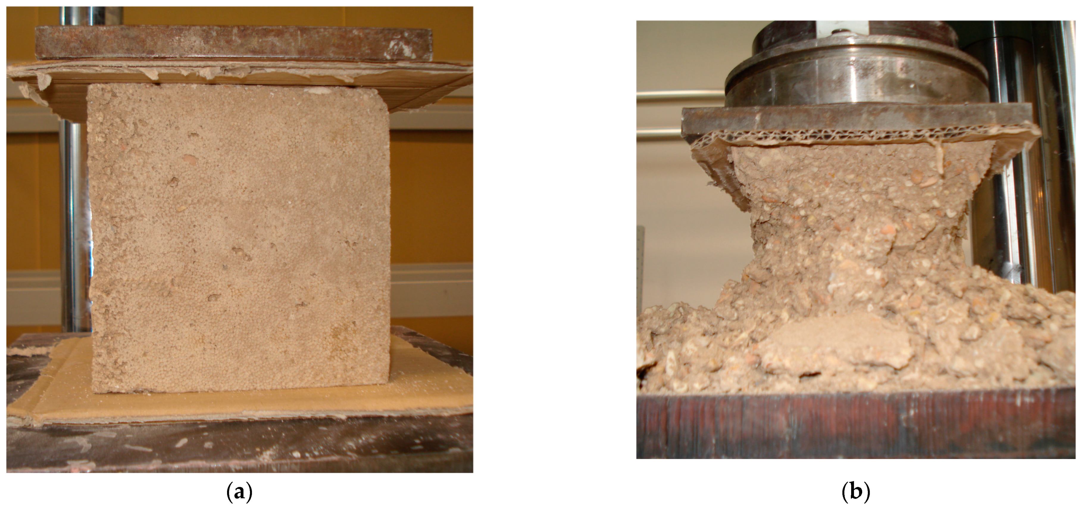
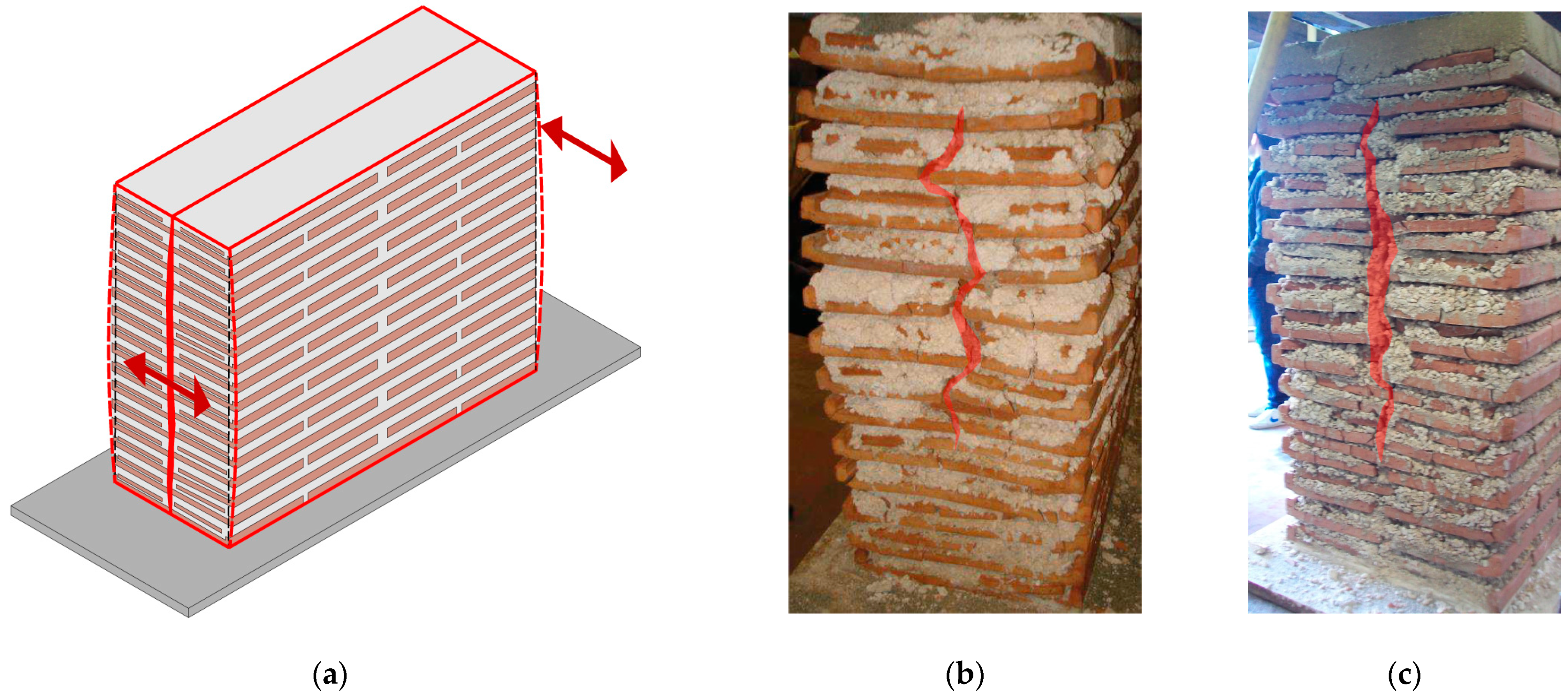
It is easy to check that the tested construction techniques can bear the operating loads, as demonstrated in Table 4.

3.2. Failure Mode

The WMT and FMT construction techniques have some differences in reaching the failure mode, even if it seems the same for both. This is due to the presence of unbroken tiles in one of the two layers of the WMT.
In particular, we can recognise two main common phases.
Firstly, in both FMT and WMT, after the first vertical cracks, by increasing the compression load further, similar vertical cracks were formed on the same sides of the specimen, and some different ones appeared always placed near the raised edges of the tile fragments. These last ones can be clearer if we consider the raised edge of the tile performing as a cantilever subject to a lateral thrust that is mainly exerted by the mortar, caused by the Poisson’s effect [22]. Typical V-shaped cracks appeared at the base of the raised edges (Figure 8a,b)) or very close to it. This resistant mechanism shows how the raised edge of the tile could have a confining effect, contributing to the strength of the specimen and causing cracks typical of these construction techniques.
After the appearance of the previous types of cracks, the common failure mode that occurred was the separation of the wall into two substantially vertical equal parts (Figure 9): it happened in all six specimens. This separation essentially followed the middle mortar joint across the thickness (Figure 8g,h), so it is closely related to the arrangement of the tile fragments of the filling layer, for WMT specimens, as shown in Figure 9b), as well as the arrangement of both of the layers in FMT specimens (Figure 9c). It is worth noting that, to reach this failure arrangement, unbroken tiles in WMT specimens had to break. This happened following different ways due to:
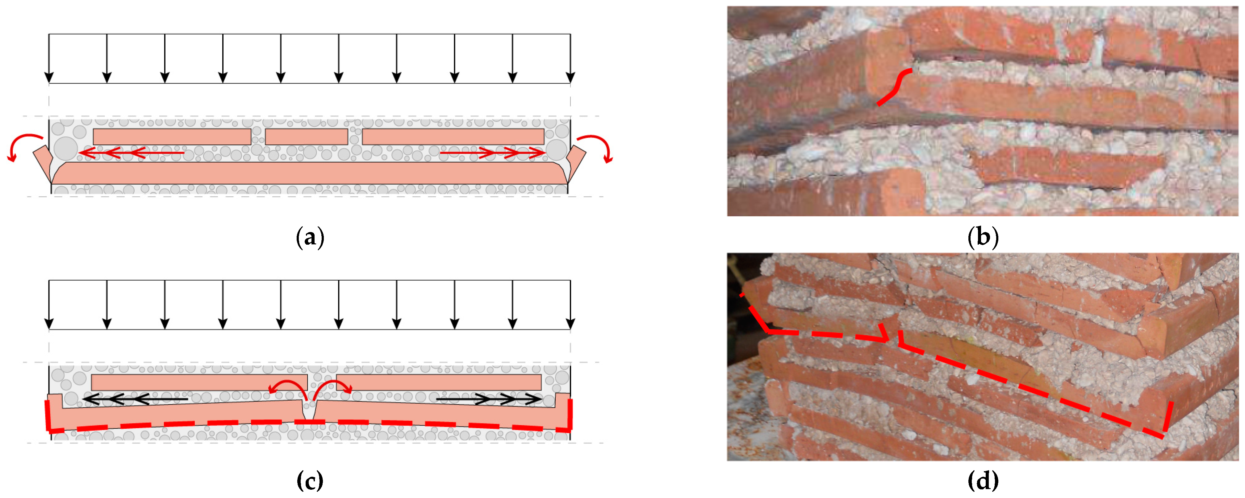
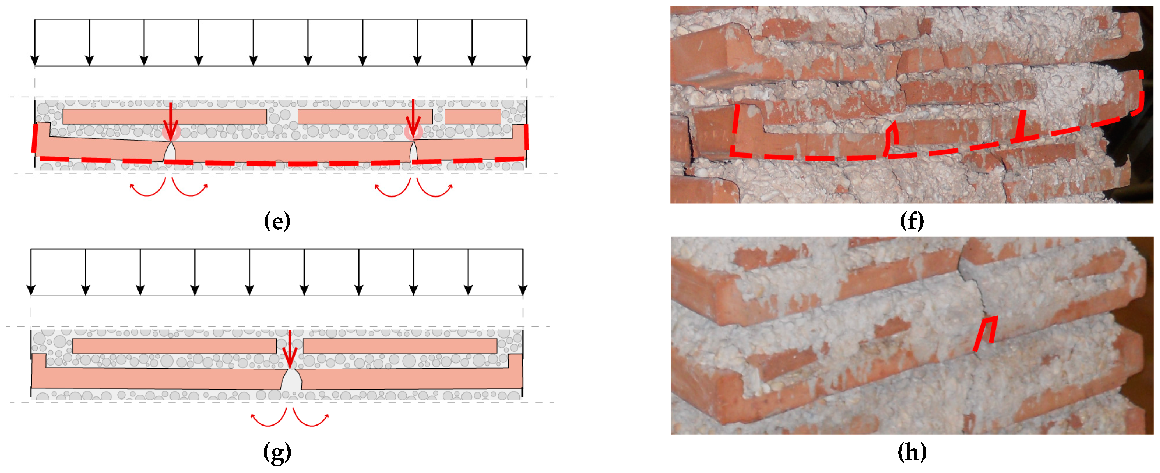
  • the Poisson’s effect, when the raised edges are still intact, as represented in Figure 8c,d). This type of breaking appeared only in WMT_1 and WMT_2;
  • the irregularities of the tile fragments as well as the presence of gravel in the mortar, which can cause local stress concentrations on the unbroken tile below, bringing to the V-inside out shaped cracks shown in Figure 8e,f. Even this type of crack is limited to WMT_1 and WMT_3.
Thus, there seem to be no significant differences between using and not using unbroken tiles because these last ones do not seem to improve the mechanical performances of the specimens. The arrangement of FMT specimens, in fact, allows the cracks to be channelled along the middle joints of the thickness, while the WMT specimens, when the unbroken tiles break, become substantially identical to FMT ones, that is, a two leaves wall.

4. Discussion

From the previous results we can deduce a workmanship for making this type of construction technique: it is important to place the tile fragments in such a way that they do not leave vertical mortar joints at half of the thickness in order to reduce the probability that the whole tiles crack in half.
However, the limited number of tested specimens can be considered the main limit of this work.
Future recommendations are increasing the number of tested specimens by compression as well as testing these two novel construction techniques by shear and by diagonal compression so as to have a look at their shear strength and shear modulus and have a more detailed mechanical characterisation as requested by several codes. This way, the modelling of these particular typologies of masonry could be performed by using results from mechanical characterization.
Furthermore, future developments will surely have to deal with the sustainability assessment by using, i.e., LCA analyses and the issue of keeping waste tiles clean from possible contaminations, which could require and impose microstructural and structural investigations as a first step in the selection of the materials and the field of their utilizations.

5. Conclusions

During the Roman period and Middle Ages, construction techniques used to reuse construction materials taken from existing buildings to realize new constructions with different methods [2]; it was a sustainable method to afford the construction of new buildings. Taking inspiration from Roman and Romanesque masonries found in the domus of Coiedii, wall specimens inspired from these two ancient construction techniques but using modern tile materials were tested to propose two simple and sustainable novel construction techniques: the first one used both unbroken and fragmented tiles (WMT), whereas the second used only tile fragments (FMT). These novel construction techniques encourage the reusing of tiles coming from CDW and CW, avoiding any reworking process of the same waste materials by using them as they come to the yard and by employing a mortar poor in binder and with big aggregates (>2 mm) too.
In addition, these types of masonry construction techniques are very simple. Thus, they do not require expert masons, permitting the saving of money and time. For these reasons, these construction techniques can be considered as sustainable and deserving of further studies for their possible use in both developed and developing countries. In fact, the preliminary results presented in this paper showed how they present sufficiently satisfactory mechanical properties, provided that their use is restricted to constructions where loads are limited, i.e., regular and small constructions (such as farm sheds) or “simple” buildings. Their compressive strengths are, in fact, in the range of 1.28 ÷ 2.27 MPa, which is comparable to some historic masonry made by rubble stone or tuff blocks, or even earth walls, rather than full brick masonries, even if their elastic modulus is certainly lower.
There seem to be no significant differences in using or not using unbroken tiles. In fact, these last ones, when compressed, tend to crack around the middle span of the thickness, thus turning WMT into substantially FMT typology. In this way, this last one seems to be preferred because it totally uses tile wastes, and even because, in monotonic tests, despite the confining effect of WMT specimens before the first cracks, the mean compressive strength of FMT specimens is slightly higher than WMT values.

Author Contributions

Conceptualization, E.Q.; methodology, E.Q. and S.L.; validation, E.Q. and S.L.; formal analysis, E.Q.; investigation, E.Q. and S.L.; resources, E.Q. and S.L.; data curation, E.Q.; writing—original draft preparation, E.Q. and M.C.; writing—review and editing, E.Q., M.C and S.L.; visualization, M.C.; supervision, E.Q.; project administration, E.Q.; funding acquisition, E.Q. All authors have read and agreed to the published version of the manuscript.

Funding

This research received no external funding.

Institutional Review Board Statement

Not applicable.

Informed Consent Statement

Not applicable.

Data Availability Statement

Research data is unavailable due to privacy. The data presented in this study are available on request from the corresponding author.

Acknowledgments

The authors would like to thank Margherita Grandoni and Alessandra Marinelli for their help in building the wall specimens, and Andrea Conti and Franco Rinaldi for their help in technical laboratory.

Conflicts of Interest

The authors declare no conflict of interest.

References

  1. Vieira, C.S.; Pereira, P.M. Use of Recycled Construction and Demolition Materials in Geotechnical Applications: A Review. Resour. Conserv. Recycl. 2015, 103, 192–204. [Google Scholar] [CrossRef]
  2. European Parliament. European Union Directive 2008/98/EC of the European Parliament and of the Council of 19 November 2008 on Waste and Repealing Certain Directives. Off. J. Eur. Union 2008, 51, 3–30. [Google Scholar]
  3. European Commission (DG ENV) Service Contract on Management of Construction and Demolition Waste—SR1, Final Report Task 2, Bio Intell Serv. 33; Bio Intelligence Service: Paris, France, 2011.
  4. Robayo-Salazar, R.; Valencia-Saavedra, W.; Mejía de Gutiérrez, R. Reuse of Powders and Recycled Aggregates from Mixed Construction and Demolition Waste in Alkali-Activated Materials and Precast Concrete Units. Sustainability 2022, 14, 9685. [Google Scholar] [CrossRef]
  5. Mariaková, D.; Mocová, K.A.; Pešta, J.; Fořtová, K.; Tripathi, B.; Pavlů, T.; Hájek, P. Ecotoxicity of Concrete Containing Fine-Recycled Aggregate: Effect on Photosynthetic Pigments, Soil Enzymatic Activity and Carbonation Process. Sustainability 2022, 14, 1732. [Google Scholar] [CrossRef]
  6. Robayo-Salazar, R.A.; Valencia-Saavedra, W.; de Gutiérrez, R.M. Construction and Demolition Waste (Cdw) Recycling—As Both Binder and Aggregates—In Alkali-Activated Materials: A Novel Re-Use Concept. Sustainability 2020, 12, 5775. [Google Scholar] [CrossRef]
  7. Robalo, K.; Costa, H.; do Carmo, R.; Júlio, E. Experimental Development of Low Cement Content and Recycled Construction and Demolition Waste Aggregates Concrete. Constr. Build. Mater. 2021, 273, 121680. [Google Scholar] [CrossRef]
  8. Tošić, N.; de la Fuente, A.; Marinković, S. Shrinkage of Recycled Aggregate Concrete: Experimental Database and Application of Fib Model Code 2010. Mater. Struct. Mater. Et Constr. 2018, 51, 126. [Google Scholar] [CrossRef] [Green Version]
  9. Gomes, M.; de Brito, J. Structural Concrete with Incorporation of Coarse Recycled Concrete and Ceramic Aggregates: Durability Performance. Mater. Struct. Mater. Et Constr. 2009, 42, 663–675. [Google Scholar] [CrossRef]
  10. Ferreira, R.L.S.; Anjos, M.A.S.; Nóbrega, A.K.C.; Pereira, J.E.S.; Ledesma, E.F. The Role of Powder Content of the Recycled Aggregates of CDW in the Behaviour of Rendering Mortars. Constr. Build. Mater. 2019, 208, 601–612. [Google Scholar] [CrossRef]
  11. Durgun, M.Y. Experimental Research on Gypsum-Based Mixtures Containing Recycled Roofing Tile Powder at Ambient and High Temperatures. Constr. Build. Mater. 2021, 285, 122956. [Google Scholar] [CrossRef]
  12. Varun Raj, P.; Surya Teja, P.; Sai Siddhartha, K.; Kalyana Rama, J.S. Housing with Low-Cost Materials and Techniques for a Sustainable Construction in India-A Review. Mater. Today Proc. 2020, 43, 1850–1855. [Google Scholar] [CrossRef]
  13. Ohama, Y. International Workshop on Disposal and Recycling of Organic (Polymeric) Construction Materials. Mater. Struct. 1995, 28, 615–616. [Google Scholar] [CrossRef]
  14. Raut, A.N.; Gomez, C.P. Development of Thermally Efficient Fibre-Based Eco-Friendly Brick Reusing Locally Available Waste Materials. Constr. Build. Mater. 2017, 133, 275–284. [Google Scholar] [CrossRef] [Green Version]
  15. Rosca, B. Comparative Aspects Regarding Concrete of Structural Grade Made with Recycled Brick Aggregate with/without Fine Particles from Crushing. Mater. Today Proc. 2022, 60, 982–987. [Google Scholar] [CrossRef]
  16. Cobîrzan, N.; Balog, A.-A.; Thalmaier, G.; Nasui, M.; Munteanu, C.; Babota, F. Microscopical and Macroscopical Analysis of Recovered Bricks for Assessing Their Reusability in Masonry Buildings. Procedia Manuf. 2020, 46, 144–149. [Google Scholar] [CrossRef]
  17. Giuliani, C.F. L’edilizia Nell’antichità. Nuova Ediz.; Manuali Universitari: Carocci, Ireland, 2018; ISBN 9788843092307. [Google Scholar]
  18. Mannoni, T.I. Problemi Dei Laterizi Altomedievali. Ravenna Studi. E Ric. 2000, 7, 213–221. [Google Scholar]
  19. Giorgi, E.L.G. Archeologia Nella Valle Del Cesano Tra Suasa e Santa Maria in Portuno. 2010. Available online: https://www.antequem.it/it/Studi-e-scavi/Archeologia-nella-valle-del-Cesano-da-Suasa-a-Santa-Maria-in-Portuno-c137 (accessed on 8 February 2023).
  20. Esposito, D. Tecniche Costruttive Murarie Medievali: Murature “a Tufelli” in Area Romana; “L’Erma” di Bretschneider: Rome, Italy, 1998. [Google Scholar]
  21. Frugoni, C. L’antichità: Dai Mirabilia Alla Propaganda Politica. In Memoria Dell’antico Nell’arte Italiana, Vol. I: L’uso Dei Classici; Einaudi: Torino, Italy, 1984. [Google Scholar]
  22. Quagliarini, E.; Lenci, S.; Piattoni, Q.; Bondioli, F.; Bernabei, I.; Lepore, G.; Zaccaria, M. Experimental Analysis of Romanesque Masonries Made by Tile and Brick Fragments Found at the Archaeological Site of S. Maria in Portuno. Int. J. Archit. Herit. 2014, 8, 161–184. [Google Scholar] [CrossRef]
  23. Graziani, L.; Quagliarini, E.; D’Orazio, M.; Lenci, S.; Scalbi, A. A More Sustainableway for Producing RC Sandwich Panels On-Site and in Developing Countries. Sustainability 2017, 9, 472. [Google Scholar] [CrossRef] [Green Version]
  24. Segura, J.; Pelà, L.; Roca, P. Monotonic and Cyclic Testing of Clay Brick and Lime Mortar Masonry in Compression. Constr. Build. Mater. 2018, 193, 453–466. [Google Scholar] [CrossRef]
  25. Andreev, K.; Yin, Y.; Luchini, B.; Sabirov, I. Failure of Refractory Masonry Material under Monotonic and Cyclic Loading—Crack Propagation Analysis. Constr. Build. Mater. 2021, 299, 124203. [Google Scholar] [CrossRef]
  26. Oliveira, D.v.; Lourenço, P.B.; Roca, P. Cyclic Behaviour of Stone and Brick Masonry under Uniaxial Compressive Loading. Mater. Struct. Mater. Et Constr. 2006, 39, 247–257. [Google Scholar] [CrossRef] [Green Version]
  27. Ispir, M.; Ilki, A. Behavior of Historical Unreinforced Brick Masonry Walls under Monotonic and Cyclic Compression. Arab. J. Sci. Eng. 2013, 38, 1993–2007. [Google Scholar] [CrossRef]
  28. UNI EN 1052-1; 2001—Methods of Test for Masonry Determination of Compressive Strengt. UNI Technical Commisson: Milan, Italy, 2001.
  29. UNI EN 12390-3; Testing Hardened Concrete. Part 3: Compressive Strength of Tes Specimens. UNI Technical Commisson: Milan, Italy, 2003.
  30. UNI EN 772-1; Methods of Test for Masonry Units. Determination of Compressive Strength. UNI Technical Commission: Milan, Italy, 2015.
  31. Ministero delle Infrastrutture e dei Trasporti Norme Tecniche per Le Costruzioni. DM 17/1/2018; Gazzetta Ufficiale della Repubblica Italiana: Rome, Italy, 2018; pp. 1–198.
  32. Ministero delle Infrastrutture e dei Trasporti CIRCOLARE 21 Gennaio 2019, n. 7 C.S.LL.PP. Istruzioni per l’applicazione Dell’«Aggiornamento Delle “Norme Tecniche per Le Costruzioni”» Di Cui al Decreto Ministeriale 17 Gennaio 2018; Gazzetta Ufficiale della Repubblica Italiana: Rome, Italy, 2019; Volume 35, pp. 1–337.
  33. Quagliarini, E.; Stazi, A.; Pasqualini, E.; Fratalocchi, E. Cob Construction in Italy: Some Lessons from the Past. Sustainability 2010, 2, 3291–3308. [Google Scholar] [CrossRef] [Green Version]
  34. Quagliarini, E.; Maracchini, G. Experimental and FEM Investigation of Cob Walls under Compression. Adv. Civ. Eng. 2018, 2018, 21–29. [Google Scholar] [CrossRef]
  35. Jayasinghe, C.; Kamaladasa, N. Compressive Strength Characteristics of Cement Stabilized Rammed Earth Walls. Constr. Build. Mater. 2007, 21, 1971–1976. [Google Scholar] [CrossRef]
  36. Quagliarini, E.; Lenci, S.; Iorio, M. Mechanical Properties of Adobe Walls in a Roman Republican Domus at Suasa. J. Cult. Herit. 2010, 11, 130–137. [Google Scholar] [CrossRef]
  37. Turk, J.; Cotič, Z.; Mladenovič, A.; Šajna, A. Environmental Evaluation of Green Concretes versus Conventional Concrete by Means of LCA. Waste Manag. 2015, 45, 194–205. [Google Scholar] [CrossRef]
Figure 1. Flow chart of the methodology used.
Sustainability 15 05385 g001
Figure 2. (a) Scheme of FMT walls specimen “Fragmented Modern Tiles”, which reproduces the typical constructive technique of the Romanesque masonries composed by tile fragments; (b) a detail of layer 1; (c) a detail of layer 2. The reference Roman masonries are those found in the domus of Coiedii (Castellone di Suasa (AN), Marche, Italy). They are made by overlapping two different types of horizontal layers (Figure 3): the lower layer is made by unbroken tiles placed with the raised edge towards the outside, which crated a sort of “U shaped formwork” that was filled by a second layer made by tile fragments and mortar.
Sustainability 15 05385 g002
Figure 3. (a) Scheme of WMT walls specimen “Whole Modern Tiles”, which reproduces the typical constructive technique of the Roman masonries composed by both whole tiles and tile fragments; (b) a detail of layer 1; (c) a detail of layer 2.
Sustainability 15 05385 g003
Figure 4. (a) A cubic mortar specimen of size 15 × 15 × 15 cm3. (b) A mortar specimen with recognizable failure mode with pyramidal shapes.
Sustainability 15 05385 g004
Figure 5. (a) Scheme of the arrangement of the monotonic compression test: each wall was placed on a metal plate (1.40 × 0.55 × 0.025 m3) placed on the frame of the apparatus used for the compression test. After this, an upper steel plate (1.40 × 0.55 × 0.025 m3) was placed upon the wall. The aim of the plate is to equally distribute the vertical load applied on the wall, and all tests were carried out in load control. (b) Representative picture of the arrangement of the monotonic compression test.
Sustainability 15 05385 g005
Figure 6. Stress–strain curves of the monotonic compression tests (on WMT_1, WMT_2 and FMT_1, FMT_2).
Sustainability 15 05385 g006
Figure 7. Stress–strain curves of the cyclic compression tests (on WMT_3and FMT_1, FMT_3).
Sustainability 15 05385 g007
Figure 8. (a) Scheme of mechanism of typical V-shaped cracks appeared at the base of the raised edges; (b) Photograph of typical V-shaped cracks appeared at the base of the raised edges (WMT_3); (c) Scheme of mechanism of crack in the middle of the tile caused by Poisson effect; (d) Photograph of crack in the middle of the tile caused by Poisson effect (WMT_2); (e) Scheme of the cracking of the tiles caused by the peculiar technological-constructive system that alternates layers of whole tiles and layers of tile fragments, combined with the irregularities of the mortar, can create local stress concentrations that can cause the cracking of the tiles itself. The cracks can be just one or more depending on the number of tile fragments in the filling layer, their rigidity, and even the concentration of local stresses; (f) Photograph of cracking of a tile caused by local stress concentrations (WMT_3); (g) Scheme of cracking of the tile that follows the mortar joint; (h) Photograph of cracking of the tile that follows the mortar joint (WMT_2).
Sustainability 15 05385 g008aSustainability 15 05385 g008b
Figure 9. (a) Scheme of separation of the specimen into two parts; (b) Photograph of separation into two parts of WMT_1; (c) Photograph of separation into two parts of FMT_3.
Sustainability 15 05385 g009
Table 1. Mortar mixture proportions relative to a single cubic specimen: the value relative to the gravel, the sand, and the hydraulic lime. The water to binder ratio (by volume) was equal to 2: this is the result after some attempts to find a good consistency for the mixture obtained. The proportions of mortar mixture are relative to a unitary volume (1 m3).
ConstituentsVolumesMortar Ratio
Gravel (2 ÷12 mm)81/4
Coarse sand (0.5 ÷ 2 mm)61/3
Fine sand (0.063 ÷ 0.5 mm)41/2
Hydraulic lime2-
Water41/2
Table 2. Values of thr first crack’s normal stress (σfc), compressive strength (σmax) and relative strain (εσmax), Young modulus (E) and relative R2 of all tested wall specimens and the correspondent compaction coefficients (cn and cn–1) for WMT_3 and FMT_3.
Wall SpecimenσfcσmaxεσmaxER2cncn−1
MPaMPa-MPa--
WMT_10.961.760.030EW−12130.9933--
WMT_20.761.920.026EW−21250.9989--
WMT_30.381.280.039EW−3.11540.9670--
EW−3.22000.98710.230.23
EW−3.32520.96620.390.21
EW−3.42760.96670.440.09
FMT_11.232.220.032EF−11530.9944--
FMT_21.121.890.033EF−2980.9964--
FMT_31.082.270.034EF−3.11190.9970--
EF−3.22940.99820.590.59
EF−3.32680.99040.55−0.10
EF−3.43160.99060.620.15
Table 3. Summary of the literature values of poor construction techniques. σ m a x   is the compressive strength, and E is the Young modulus.
Construction Techniquesσmax (MPa)
Min-Max
Irregular Stone masonry (pebbles, erratic and irregular stones) [32]1.00–2.00
Irregular masonry of soft stone (tuff, calcarenite) [32] 1.40–2.20
Adobe earth walls [36]0.77–1.20
Cob earth wall [34],1.05–1.17
Rammed earth walls [35]1.69–2.35
Table 4. The results of verification for two-storey building. Values of the first crack’s normal stress ( σ f c ), compressive strength ( σ m a x ) and relative strain ( ε σ m a x ), Young modulus (E) and relative R2 of all tested wall specimens and the correspondent compaction coefficients ( c n and c n 1 ) for WMT_3 and FMT_3.
Floor height H3.5m Concrete brick roof slabWR,G1.4kN/m2
Building lengthL110.0m Overload -roof slabQk 2.0kN/m2
Building widthL28.0m
Walls thicknesss0.8m Wooden inter-floor slabWIF,G1.6kN/m2
Specific weight of masonryγ18.0kN/m3 Overload -inter-floor slabQk2.0kN/m2
N4511.36kN fk1280kN/m2
A31.36m2 γM4.2-
N/(0.65A)221.32kN/m2<fkM304.76kN/m2
Disclaimer/Publisher’s Note: The statements, opinions and data contained in all publications are solely those of the individual author(s) and contributor(s) and not of MDPI and/or the editor(s). MDPI and/or the editor(s) disclaim responsibility for any injury to people or property resulting from any ideas, methods, instructions or products referred to in the content.

