Article

Improvement of Autonomy, Efficiency, and Stress of Fuel Cell Hybrid Electric Vehicle System Using Robust Controller

by
Aissa Benhammou
1,2,
Mohammed Amine Hartani
2,3,
Hamza Tedjini
2,
Hegazy Rezk
4,5,* and
Mujahed Al-Dhaifallah
6,7,*
1
Lab of Instrumentation and Advanced Materials (LIMA), Nour Bachir University Center El-Bayadh, El-Bayadh 32000, Algeria
2
SGRE Laboratory, Tahri Mohamed University, Bechar 08000, Algeria
3
Sustainable Development and Computer Science Laboratory SDCS-L, Ahmed Draia University—Adrar, Adrar 01002, Algeria
4
Department of Electrical Engineering, College of Engineering in Wadi Alddawasir, Prince Sattam bin Abdulaziz University, Al-Kharj 11942, Saudi Arabia
5
Department of Electrical Engineering, Faculty of Engineering, Minia University, Minya 61111, Egypt
6
Control and Instrumentation Engineering Department, King Fahd University of Petroleum & Minerals, Dhahran 31261, Saudi Arabia
7
Interdisciplinary Research Center (lRC) for Renewable Energy and Power Systems, King Fahd University of Petroleum & Minerals, Dhahran 31261, Saudi Arabia
*
Authors to whom correspondence should be addressed.
Sustainability 2023, 15(7), 5657; https://doi.org/10.3390/su15075657
Submission received: 20 January 2023 / Revised: 17 March 2023 / Accepted: 21 March 2023 / Published: 23 March 2023
(This article belongs to the Special Issue Sustainable Electric Power System and Renewable Energy)

Abstract

:
Among issues facing the transportation sector today is the limited autonomy of electric vehicles, which are highly reliant upon energy storage systems. Considering this issue as the current research gap, researchers seek to prolong vehicle dependability through renewable-free and sustainable energy that tackles negative environmental impacts. This research exploits the electric vehicle’s kinetic energy to improve its performance and reliability. It uses fuel-cell resources and supercapacitors hybridized with lithium-ion batteries, in addition to DC generators connected to front wheels that convert their rotations into energy contributing to the vehicle’s overall power balance. A state machine-based energy management strategy computes fuel-cell setpoint power, while a dual-loop structure uses a super-twisting controller for DC bus voltage regulation and recovery, in addition to tracking banks’ setpoint currents. A speed controller-based artificial intelligence is proposed to reduce power losses and enable accurate tracking of running trajectory to improve vehicle mechanisms. The simulation results using Matlab Simulink software proved the proposed vehicle’s feasibility by adopting the free kinetic energy of additional DC generators that provided 28% of its total power requirements, resulting in superior supply efficiency reaching 98%. Thus, the stress on FC and battery was minimized by 21% and 10%, respectively, in addition to reducing fuel consumption by 39%, so the vehicle autonomy was extended, and its reliability was enhanced and supported, as targeted.

1. Introduction

Nowadays, the problem of EV autonomy is among the biggest challenges in the world, especially with the emergence of COVID-19, which prompted researchers to develop energy systems for energy independence and improved systems autonomy, as well as improved efficiency related to reducing the stress on the primary and vital resources.
The diversity of sources remains an important matter to ensure the independence of the electric vehicle, which depends mainly on smooth control, whether in energy management, control of converters, and even control of the mechanical part of the electric vehicle, which has been studied in this paper.
Due to rising research and development, HEVs are becoming increasingly popular worldwide [1,2]. At the moment, hybridization technology has reached a more mature stage, and incorporating a wide variety of environmentally green resources into autos has attracted much interest from both the commercial world and the academic world to maximize EV autonomy [3,4].
Traditional research hybrid electric vehicles that were content to use conventional resources such as batteries, fuel cells, and supercapacitors all suffered from the same problem: limited efficiency and autonomy [5,6]. The stress on resources remains a problem parallel to hybrid energy systems, where the only solution for the flow of resources and energy distribution is energy management systems [5,6,7].
Improving fuel consumption while adjusting the efficiency of the system is among the most complicated matters on the level of electric cars, especially since the field of energy hybridization requires high-precision controllers, neither in terms of energy control nor in terms of mechanical control, which in turn plays an essential role in this field [8,9].
HEVs fueled by FC are now among the EVs that may be found on the road today. Since it consumes fuel yet produces no pollution, FC is one of the many environmental sources [10]. In addition to the FC, incorporating a BESS into the HEV system can be used to maintain energy balance [11,12].
The purpose of the BESS is to keep the DC bus voltage stable at a predetermined level [13], combined with the SC, an auxiliary ESS utilized to regulate the power changes caused by transients. It comes before the BESS intervention to preserve the power balance between resources [14].
Through the principle of clean energy in the world, the authors decided to exploit the kinetic energy of the EV by adding generators that convert kinetic energy into electrical energy.
Green energy resources reduce carbon emissions and pollution from traditional energy industries. Generating electricity from this source is very suitable for various applications in the field of transportation, especially with the addition of a robust controller for electrical converters such as model predictive control [15,16] and super-twisting [17,18].
The problem statements associated with this research topic are centered on the restricted autonomy of EVs, the sources of stress, fuel consumption, the stability system, and efficiency, considering the adverse effects on the environment (pollution).
In addition to exploiting the EV’s kinetic energy, the primary objectives of the research’s topic include improving EV’s behavior through the extension of EV’s autonomy while maintaining high system efficiency and reducing stress applied to the primary sources [17,19].
The original contribution of this study is to examine the behavior of HEVs while exploiting their kinetic energy concerning the sources’ stress, the system’s efficiency, and EV autonomy using a robust controller.
The remaining portions of this paper are organized and described as follows. The study’s focus on HEVs is covered in Section 1, wherein their respective models are described. The fundamental concepts and subsystems of the HEV are outlined in Section 2. The most important objectives of this study are deliberated in Section 3. The revealed results and debates are included in Section 4, including the results of suggested topologies and control techniques. Lastly, this research’s conclusions and potential future directions are presented in Section 5.

2. Hybrid Electric Vehicle Configuration

Figure 1 shows the power train configuration of the hybrid electric vehicle model used in this study. The traction part is ensured by AC motors in the rear (2WD), with developed performances and high efficiency. These motors are connected to a DC-AC inverter and are controlled by a robust algorithm speed (ANFIS-DTC-SVM).
The power part contains FC, SC, and BESS connected with special converters; each converter is controlled by a super-twisting-based sliding mode control (ST-SMC). The freedom of front wheels has allowed the addition of DC generators to exploit the EV’s kinetic energy as an additional power source.
The generators are linked with a gearbox, where the output of DC generators is connected to a boost converter controlled by MPPT to secure the same DC bus voltage. A classic EMS has been determined to track the HEV’s behavior and determine the study’s positive points.
Table 1 represents the main HEV parameters used in this study:
Equation (1) describes the EV power demand PLoad using longitudinal vehicle dynamics [7].
P L o a d = V 0 ( ( m · g · f · cos ( θ ) + 1 2 ρ a i r × V 0 2 × A × c d ) + ( m · g · sin ( θ ) + m · δ d v d t ) )
where V0 is the EV velocity, m is the EV weight, g is gravitational acceleration, A is frontal area, f is the rolling coefficient, θ is road slope, Cd is air coefficient, ρair is air density.

3. Modelling of the Proposed HEV

HEV consists of several essential components that work to maintain coordination in performance by adjusting the control system with converters and sources. Each subsystem is explained in the following parts to explain the HEV accurately.

3.1. Modelling of the HESS

3.1.1. Li-Ion Battery Model

Batteries are considered one of the most critical energy storage systems due to their electrochemical nature in charging and discharging [20]. The limitations of traditional batteries such as lead-acid, NIMH, and others prompted the researchers to produce so-called lithium-ion batteries. The high energy density and efficiency of Li-ion batteries has made them more attractive for traction systems in recent years [21].
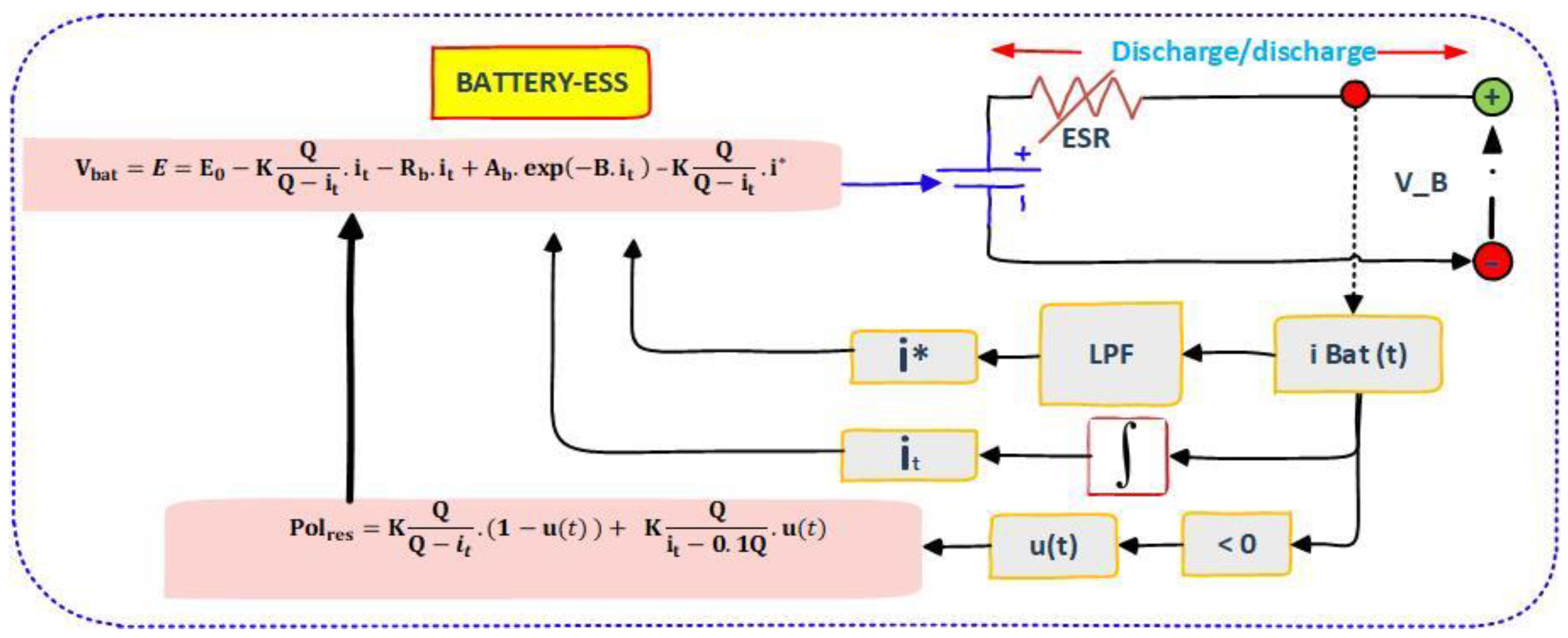
The mathematical battery model included under the SPS is based on a modified Shepherd curve fitting model, which is also based on voltage polarization. It is added to the mathematical expression of the battery discharge voltage to clearly show the battery’s SOC’s impact on its performance [22].
Additionally, the polarization resistance is considered using a filtered battery current rather than the actual battery current to maintain simulation stability [23].
It has been included as a diagram to simplify the mathematical model of the BESS, as shown in Figure 2 [17,18].

3.1.2. Supercapacitor Model

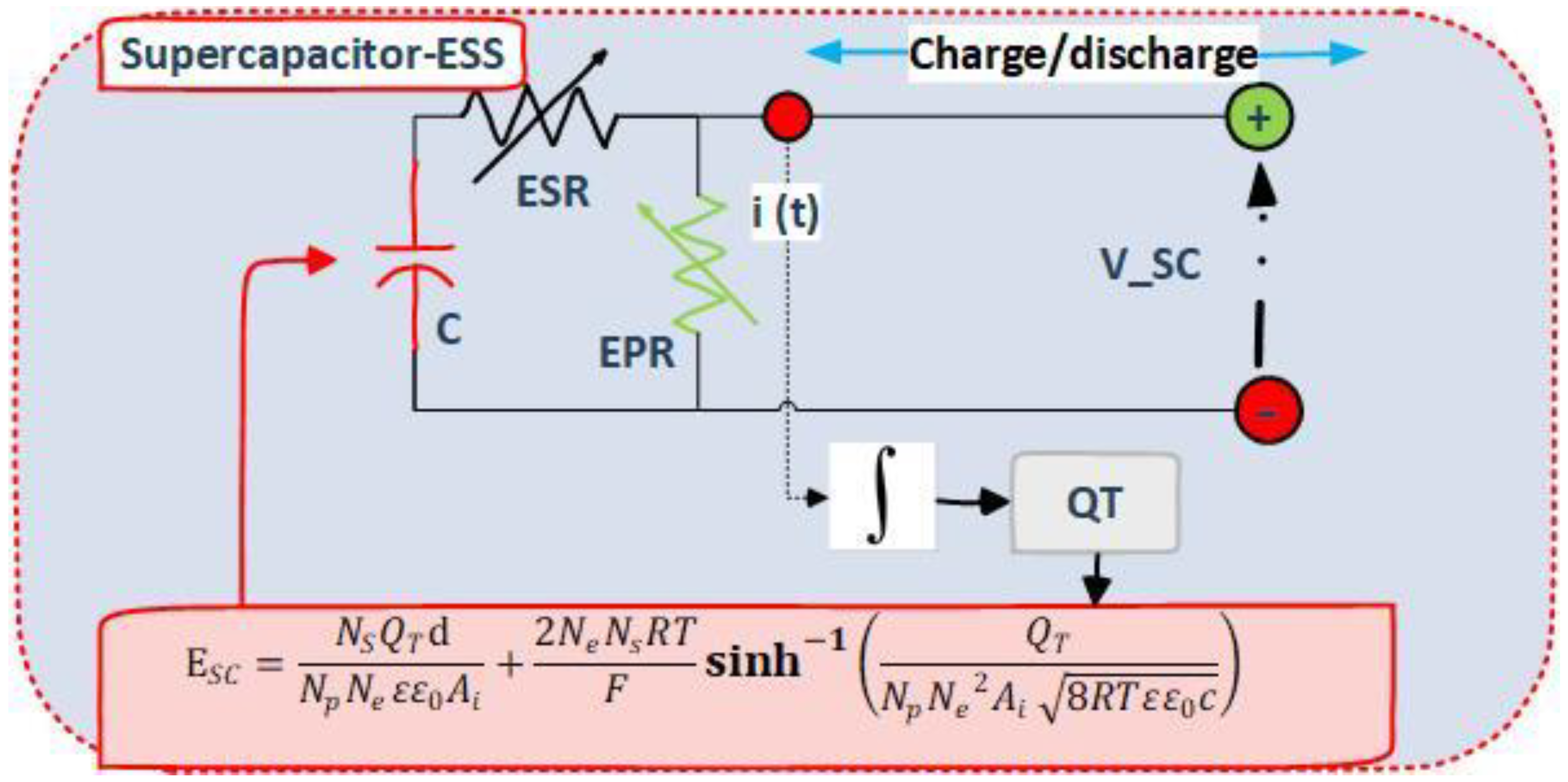
SCs are among the essential fast-intervention energy storage devices in transitional regimes. Two porous carbon electrodes submerged in an electrolyte are the main components of the SC [24]. The electrolyte’s negative ions move to the positive electrode, whereas the positive ions move to the negative electrode when a voltage is applied across the electrodes of SC [25]. The SC gets the name of a double-layer capacitor when the layer of charge of each electrode is created. It helps attain a high capacitance because of the electrode’s porosity and the proximity of the charges [26].
The mathematical model of SC is presented as a diagram illustrated in Figure 3 [18].

3.2. Modeling of the FC

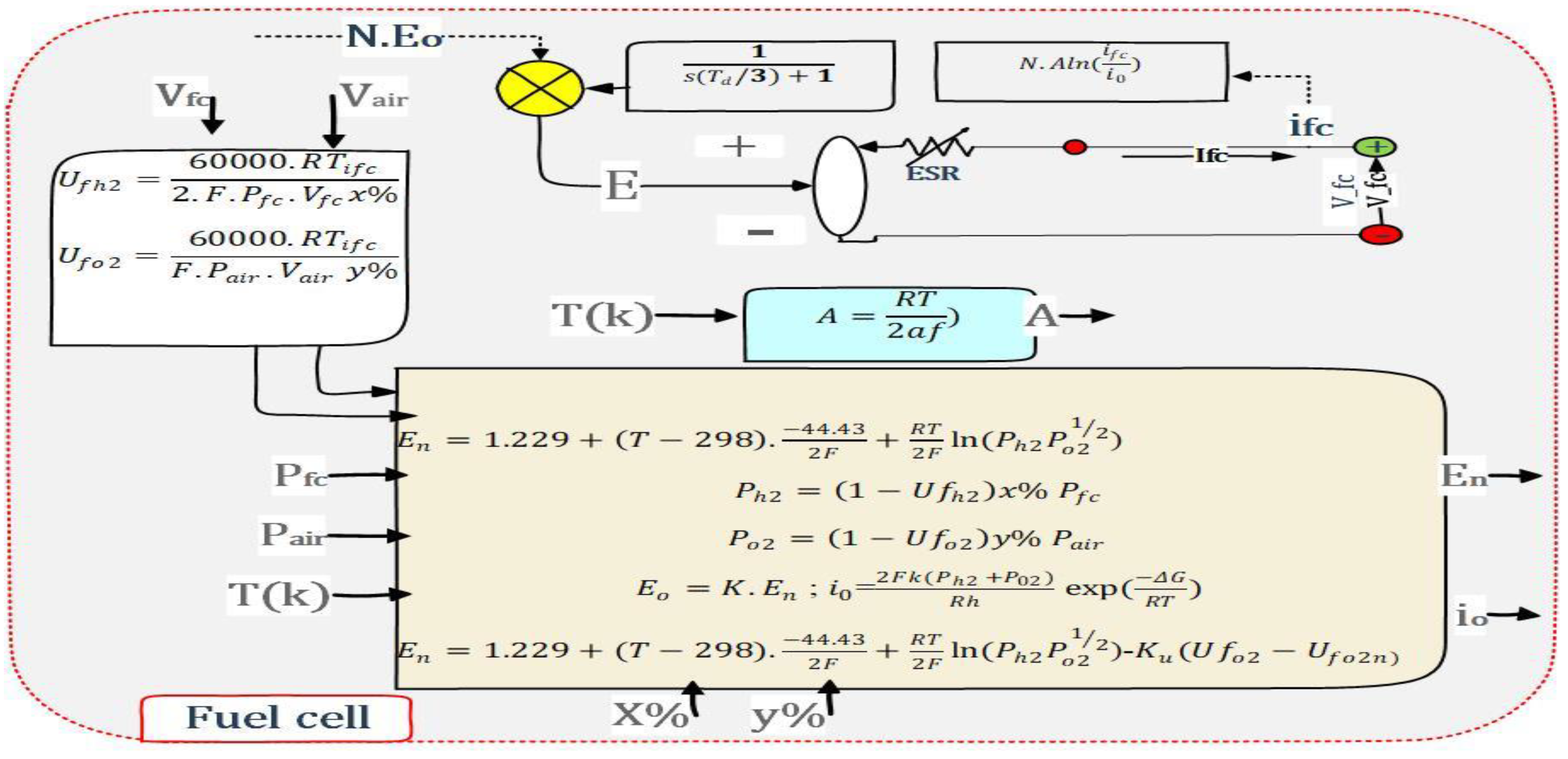
The fuel cell resource is one of the most important clean energy sources. It has been a significant development in traction systems, where it is a renewable source that converts chemical power into electrical energy. Respecting the first principle of thermodynamics, the FC produces energy by oxidizing hydrogen without a mechanical handle [27,28]. Figure 4 explains the principle of cell work by including the most important mathematical equations [7,17,27].

3.3. Exploiting of EV’s Kinetic Energy

3.3.1. DC Generator

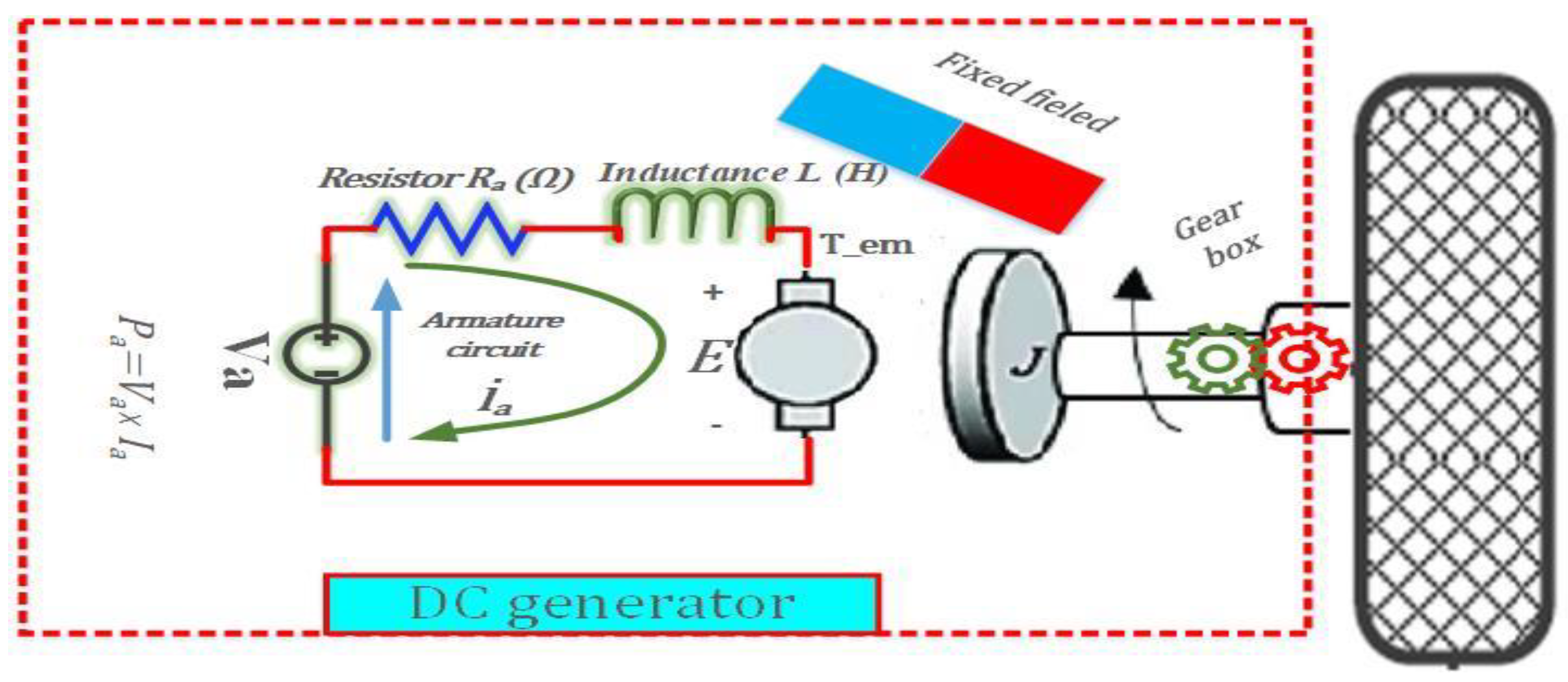
PMDCGs are generators that use permanent magnets rather than rotor windings to convert mechanical energy into direct current. These generators can be connected to turbines, diesel, and hybrid cars without requiring a separate DC supply, slip rings, or contact brushes. These machines can be used in machines that generate energy from wind and water and do not call for special working conditions. Wind energy is the primary concept behind using the PMDCG in the EV kinetic energy [17,29,30,31,32].
Figure 5 represents the EV front wheel connected to the DC generator.

3.3.2. Exploiting of EV’s Kinetic Energy Using DC and AC Generators

Exploiting the kinetic energy of electric vehicles allows for the production of DC energy by adding PMDC generators. It is also possible to produce AC energy using AC generators [17]. It is sufficient to connect the DC-DC boost converter to each generator, which transmits the same DC bus voltage to maintain the same DC bus voltage when using DC generators. In contrast, in the case of using AC generators, it is necessary to use the AC-DC converter in addition to the DC-DC boost converter, which may affect the system’s efficiency [33]. Regarding weight, DC generators are somewhat heavier than AC generators. DC generators are more expensive than AC generators [32].

3.4. Design and Control of Power Converters

3.4.1. Bi-Directional and Boost DC-DC Converters

The KCL and KVL laws can be used to determine the expressions of converter dynamics. The input/output voltage and current conversion percentages in the bidirectional converter are V H i g h = V L o w / ( 1 D ) and I L o w = I H i g h / ( 1 D ) . The general BDC’s TF is obtained by converting the time mode signal to the S mode signal to get the close-loop design (control performances) [18], where D is the duty cycle.
The primary condition for tuning the smooth DLC controller considers the external loop controls DC voltage by generating the reference current to the inner loop [25]. To the dynamic of the BDC, the outer loop is slower than the inner loop.
For fast responses, it necessary to ensure that the inner loop bandwidth is three times the outer loop bandwidth, and the SC current loop must be greater than the battery current loop. The input/output voltage conversion percentage in the boost converter is V L o w = V H i g h t . ( 1 D ) .
As shown in Figure 6, the BESS and SC ESS are connected to a bidirectional DC-DC converter; it has been reformulated in a detailed diagram of the used DC/DC converters with their control structures [18].

3.4.2. LPF Control

FBC divides the load current into HF parts handled by the switching controller during transients and LF parts flattened by the battery at steady states, and it is also due to the slower charge/discharge compared to the faster charge/discharge of the supercapacitor due to BESS and supercapacitor’s different internal characteristics.
Additionally, ST-SMC is the hybrid system’s controller (non-linear). It regulates and recovers the bus voltage and tracks battery setpoint currents, while the HCC regulates the SC’s current flowing [18].

3.4.3. The Super-Twisting Controller

The chattering impact is the resilience cost of control signals, generating reliability control challenges. One of the advantages of SMC is its superior resistance to matching disruptions, but this comes at the expense of the system’s overall resilience. According to that, the chattering phenomena can be mitigated in a few different ways [18,34,35,36,37,38]:
Using saturation or sigmoid functions rather than discontinuous switching functions;
Utilizing an adaptive law to change the switching gain dynamically;
Utilizing high-order SMC methods.
The first solution is less resistant to interruptions, the switching gain estimation for the second solution may climb monotonically owing to the lack of perfect sliding motion in actual practice, and the third solution’s gain stability calculations may be relatively challenging.
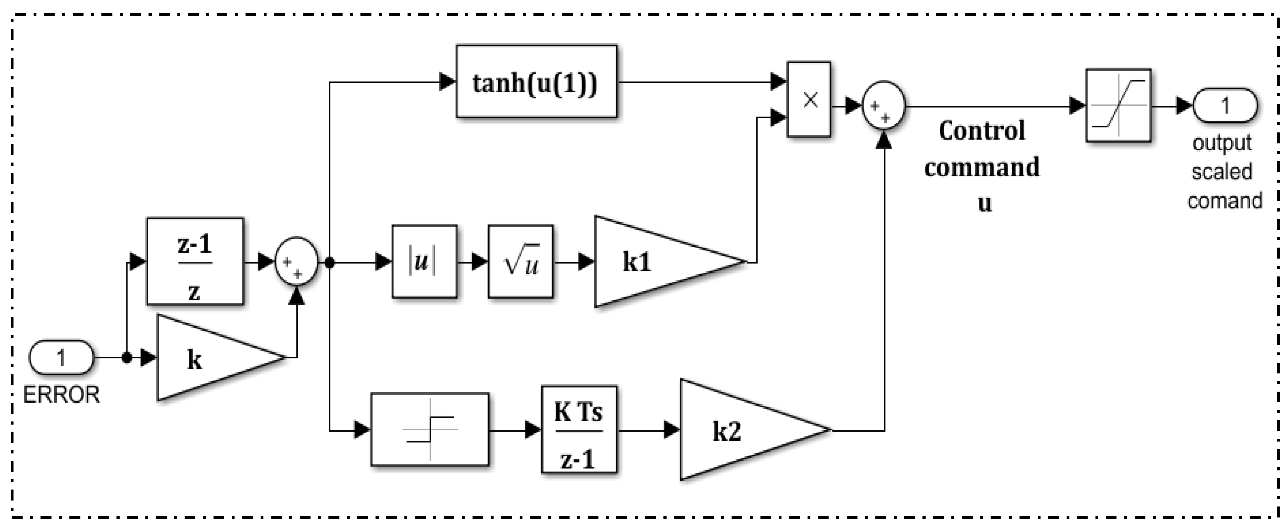
To perform the control process, the second-order sliding mode controller (SO-SMC), such as the ST-SMC specified in Figure 7, needs just feedback information on the sliding variable “S”. The experimental variable that determines how quickly a response is given is denoted by the letter K.
Setting K = 1 is the first step in the tuning process; if the system reacts slowly, it will progressively increase, and if it responds quickly, it will gradually decrease. This process will continue until accurate convergence. Intended responses are achieved. The trial-and-error tuning approach determines the ideal gains (K1, K2) that keep the current and duty cycle around 0.9 and 1.1 of their setpoints to discover the optimal gains that will be utilized to tune the system [18,34,35,36,37,38].

3.5. The ANFIS DTC-SVM Speed Controller

The ANFIS controller is considered one of the most robust controllers based on artificial intelligence techniques (neural with fuzzy), which depends on its performance on a pre-defined database. The ANFIS controller can learn the distinguish mapping that contains the inputs and output of the system’s signals. The adaptive neuro-fuzzy inference strategy is not based directly on the arithmetical description of the system; instead, it is based on the database (output/input) and the membership selected [39].
The definition of the (inputs)/output database, defined by (the speed error and its derivative)/torque, specifies the ANFIS controller’s general structure. The error is handled by the fuzzy controller’s memberships, which allows the generation of outputs as the neural controller [40].
Based on the SVM method, the traditional DTC-SVM algorithm consists of three PI controllers that produce reference values for ensuring smooth switch control. Our proposal to create a torque reference in this study is to replace the speed PI controller with the ANFIS controller for the control bladder and avoid losses as much as possible. The references [17,37,41,42] contain a detailed explanation of the ANFIS-DTC SVM.
Figure 8 shows the control technique of the EV’s rear wheels based on the ANFIS-DTC-SVM, where Figure 8a represents the general control technique of each wheel, and Figure 8b represents the ANFIS controller structure with the used membership.

3.5.1. SVM Unit

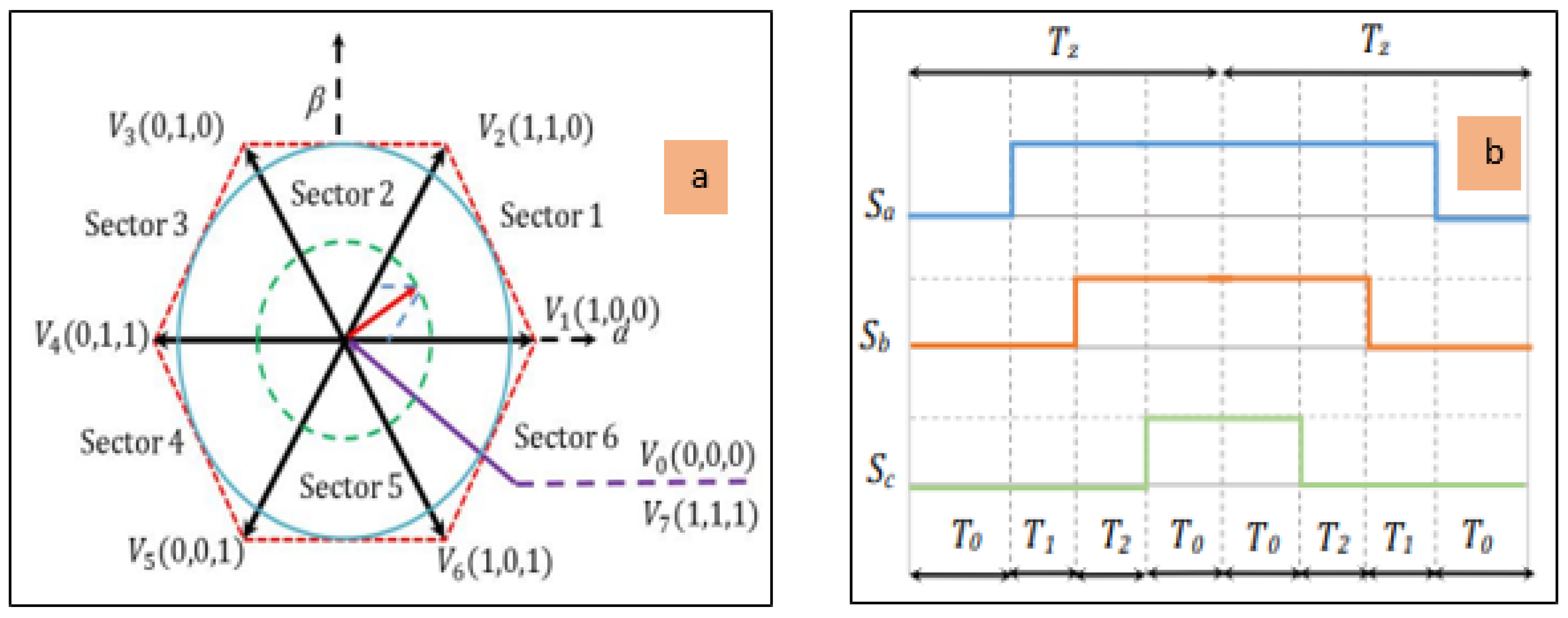
By modulating the components of the obtained reference voltage using the SVM approach, the command states for the inverter are created. The three vectors that encircle each sector are depicted in Figure 6. Calculations of vectors are used to determine the amount of time required to apply each vector, and the remaining time is spent applying the null vector. The vector durations T1 and T2 can be found using Equation (2) [17,19].
T 1 = T s 2 . v D C ( 6 v β s * 2 v α s * ) T 2 = 2 T s v D C v α s *
Vαs and Vβs are reference voltage vectors, T1 and T2 are the corresponding vector durations, Ts is the sampling time, and vDC is the DC bus voltage. The calculation of duty cycles based on the SVM algorithm for the first sector is expressed in Equation (3).
T a = T s T 1 T 2 2 T b = T a + T 1 T c = T b + T 2
Figure 9 represents the space vector voltage and duty cycle diagram for sector 1.
Table 2 shows the command state of each switch generated from the SVM algorithm.

3.5.2. ANFIS Controller

ANFIS is a form of artificial intelligence that operates based on a neural network and is compatible with the Takagi–Sugeno fuzzy inference method, as seen in Figure 8b. This method uses an existing observation database to construct the fuzzy inference system (input and output) [43]. The structure has one output and two inputs (error and derivative). Moreover, it has layers of the ANN structure (control signal u). The if–then rules can be obtained by utilizing the Equation (4) [40,43,44].
Rn = If M1n (e) and M2n (e), then f =Pn e(t) +qn Δe(t) + rn
The terms ‘n’ represents the rule number, M1n and M2n are membership functions of fuzzy, and Pn, qn, and rn are the parameters of the nth rule.
Calculating the degrees of membership functions based on the input variable, also known as basic fuzzification, is an important part of the process. Equation (5) is used to calculate each layer node, while an, bn, and cn are parameters that are predetermined values. Layer 2 is the inference layer, and Equation (6) determines the wn values, representing the second layer’s outputs using the error and its derivative (e and Δe). The third layer is the normalization layer, and its height may be determined using the weights of the two layers that came before it, as shown in Equation (7).
M 1 n = 1 1 + x c n a n b n
w n = M 1 n ( e ) × M 2 n ( Δ e )
ω n = w n n w n
Equation (8) can describe the nodes that comprise the fourth layer, where P, q, and r represent a different set of parameters, and the term u stands for the control signal.
ω n u = ω n ( P n e ( t ) + q n Δ e ( t ) + r n )
Layer 5 is the final layer (output layer), and it calcules the sum of output signals from the nodes in the preceding layers to obtain the next part of the rules [45].
n ( ω n u ) = n w n u n w n

3.5.3. Flux and Torque Estimators

Equation (10) illustrates the calculation of the flux components (φαs φβs) [19,46].
φ α s = 0 t ( V α s R s i α s ) d t φ β s = 0 t ( V β s R s i β s ) d t
The stator flux φs and electromagnetic torque can be computed as [19,42].
φ s = φ α s 2 + φ β s 2 T e m = P ( φ α s . i β s φ β s . i α s )
Tem and P are the electromagnetic torque and the number of pole pairs.

3.6. The Proposed Energy Management Strategy

SM is an essential technique for managing energy based on specific conditions and rules. Each rule or state of an EMS is defined following heuristics or prior empirical information. A rule-based solution that is both basic and widely used is utilizing state machine control. Due to this, this method’s efficiency depends on the designer’s expertise with the operation of each component that goes into making up the system.
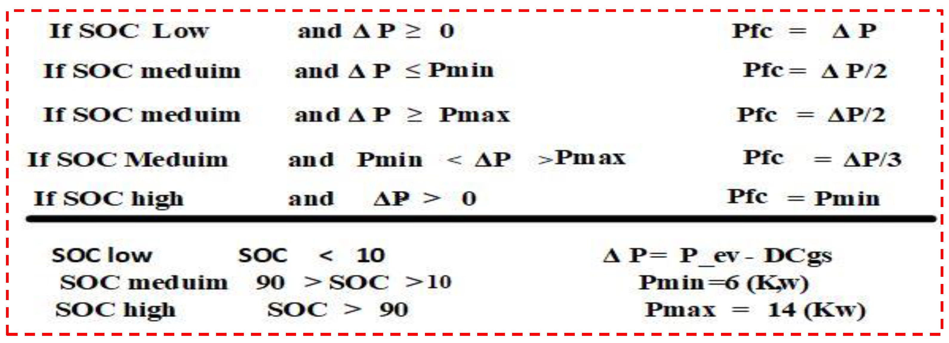
Figure 10 provides a more detailed explanation of this method and illustrates its algorithm applied to a hydrogen fuel cell hybrid electric vehicle (HEV). The fuel reference power is determined by applying the conditions to the calculation (battery state of charge and powers of load and generators).
The fuel cell is capable of operating in either the load-following mode (also abbreviated as LF) or the load-leveling mode (also abbreviated as LL) [7,17,47].
The conditions of this SM-EMS respected the balance between fuel consumption and the battery’s SOC [10–90] (%) to conserve the battery’s cycles by avoiding floating or bulk charging [7,17,47].

3.7. Autonomy and Stress Analyses

As represented in the literature, the autonomy of the electric system is one of many problems in their applications, especially in electric vehicle applications. Each EV’s autonomy depends on the quantity of energy in its sources, where EVs can work without refueling or recharging ESSs by external sources that are addressed [48].
For the case of HEV, the specified EV autonomy is as follows. At first, the HEV’s sources are thought about with the prospect of securing the typical distance while maintaining its nominal function.
After that, the proposed topologies (software and hardware) are considered, and the feasibility of their use in a specified hybrid system, considering their benefits, are evaluated (cost, difficulty, and realizations). After establishing that there is a chance of embodiment taking place, the system’s autonomy is established by:
Determining the added distance gained through autonomy improvement applications, determining the amount of fuel saved by improvement applications, and the impact of this improvement on the system’s stability and the source’s function [49,50,51,52].
Reducing the stress on the sources is one of the most significant improvements needed in the hybrid system, as it improves the system’s autonomy, ensuring the sources work for a more extended period and thus increasing the system’s efficiency [52,53,54].
Figure 11 represents an explanation schematic of relationship between the autonomy and sources of stress studied in our work.

3.8. The Supply Efficiency

The assembly of many sources helps to increase the efficiency of the hybrid electrical system by providing the necessary energy and ensuring a smooth balance of power within the hybrid system [49,50].
Efficiency improvement processes in hybrid systems include two main points: the efficiency of improvement-based software and improvement-based hardware [55]. Software technique improvement is applying robust energy management strategies and improving innovative methods [17,18].
Efficiency can also be improved by optimizing the converters’ control and the traction system control of the electric vehicle. The second part (hardware) improves efficiency by adding many sources with quick responses, respecting the nominal conditions of the system function, and avoiding pressure that causes significant losses [56,57,58].

4. Results and Discussion

After accurate modeling of the HEV, this part describes and discusses the main obtained results. The analysis of the scenario’s results highlights the impact of the robust controller and the EV kinetic energy using DC generators, improving the HEV’s dynamic.
The results are presented, respectively, and include the mechanical responses of HEV’s motors (speed, torque, current, and flux), the power balances system, BESS and FC behaviors in each topology, the bus voltage stability, and finally, efficiencies and the errors of controllable variables based on ST-SMC controller. Table 3 presents the running scenario of HEV for simulation tests.
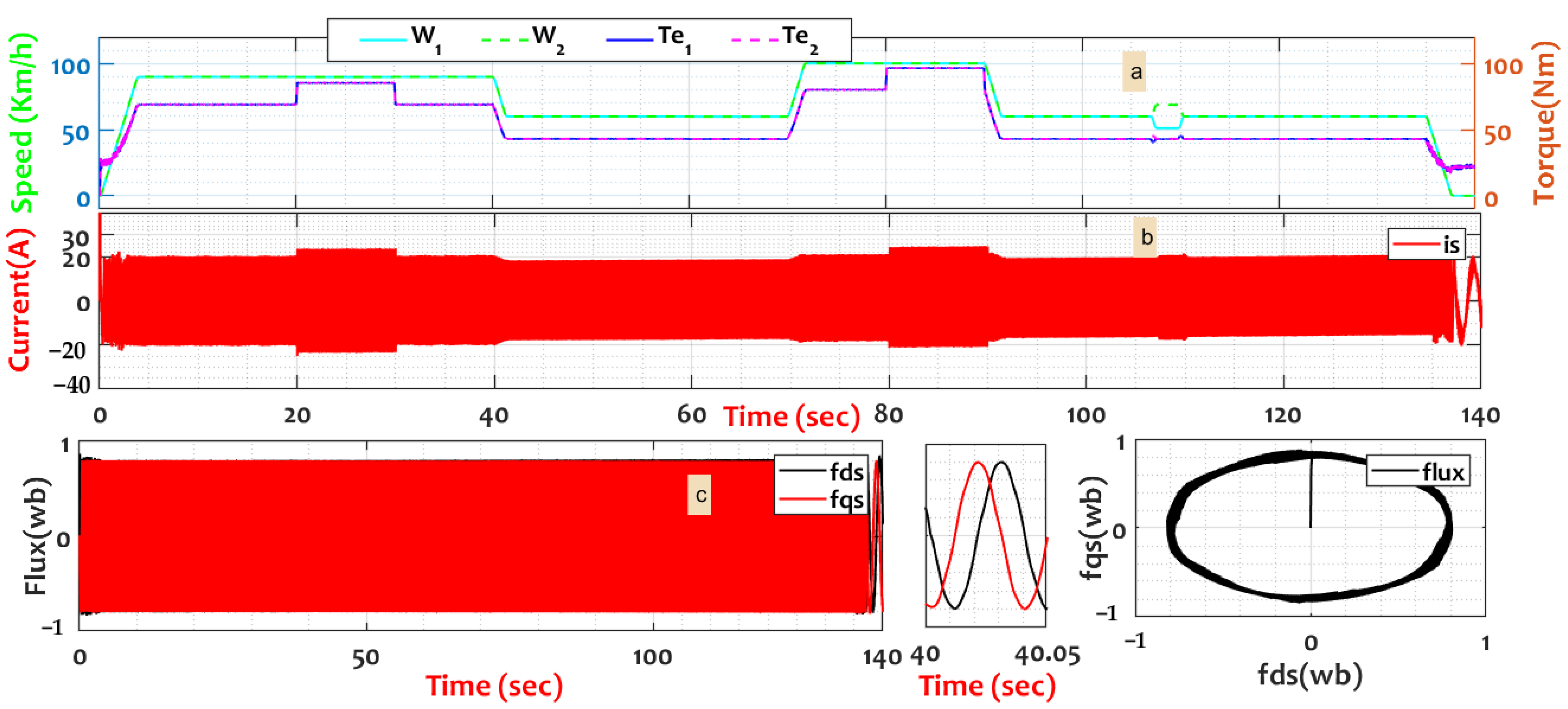
Figure 12a displays the HEV’s wheels’ speed and electromagnetic torque responses regulated by the ANFIS-DTC-SVM algorithm, where the predicted speed and reference speed are the same, in addition to the response of the electromagnetic torque, which shows the vehicle control reliability in [20–30] second, and [80–90] seconds (s).
The EV went along its pathways with speed values, ramps, and detours, controlled by the robust ANFIS controller (the ED creates the wheels’ setpoint speed).
Figure 12b shows the stator current of EV’s motor without waves, where the beginning current was 138 (A) with simultaneous response with the load. Figure 12c shows the flux form by managing the nominal flux value and the smooth circular shape of the flux compound ring with a diameter of 0.8 (web) without being impacted by load variation. Further, all topologies have the same speed, torque, and currents.
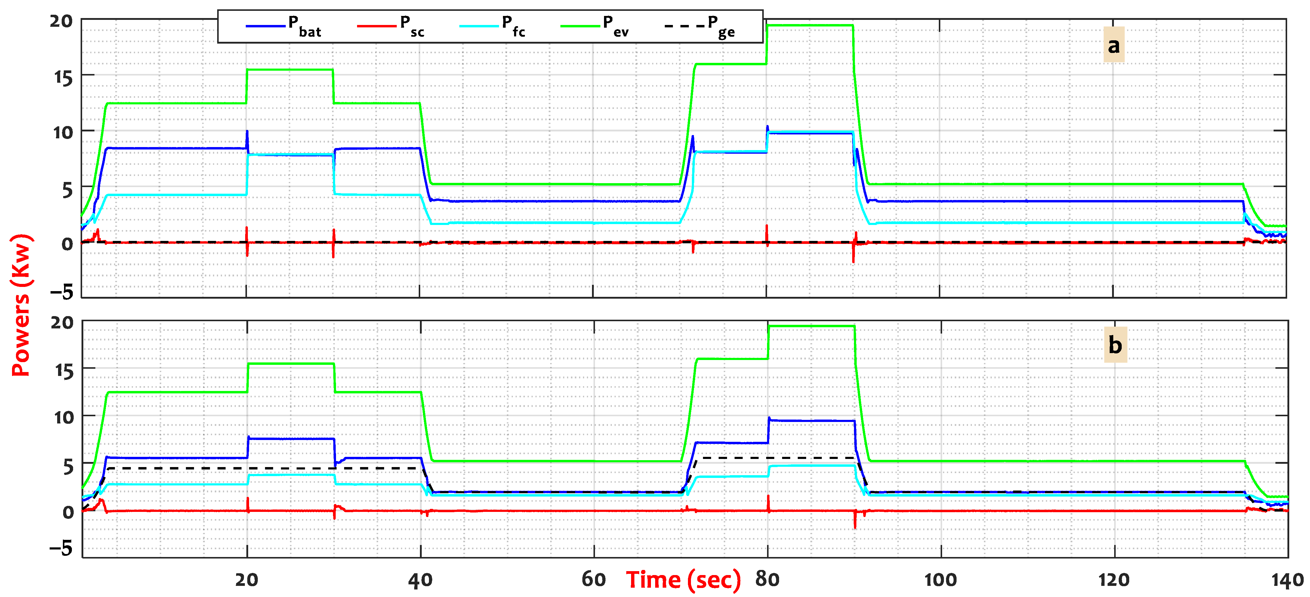
Figure 13 shows the proposed HEV power balance profiles based on SM-EMS. Besides DC generators, the supplied energies from FC, battery, and SC highlight the influence of kinetic energy on the HEV’s stability.
HEV relies heavily on the BESS as the primary ESS, which works in parallel with the rest of the sources (FC and supercapacitor) to secure the EV’s supply. The battery and SC are considered energy storage units. The battery contributes to the permanent systems for energy balance, and the capacitor takes care of the transitional systems due to the physical properties of batteries. In the basic scenario (without generators), the battery and FC secure the needed power for the EV in [0–40] (s), where the FC contributed by 8.5 (kW) and the battery contributed by 5 (kW).
The installation of generators reduced the BESS and FC powers to 5.5 (kW) and 3.5 (kW), respectively. Exploiting kinetic energy reduces BESS power in [40–70] (s) compared to the basic topology. The DC generator’s power reduced the FC generated power in [70–90] (s). During [90–140] (s), HEV kinetic energy helped to reduce the generated BESS’s power.
In general, exploiting EV’s kinetic energy contributed to 28 (%) of EV’s power using DC generators, in addition to reducing the battery and FC power production. This contribution will decrease the amount of power produced by the BESS and the FC and will be reflected in subsequent results regarding the discussion of stress and the amount of fuel consumed.
Figure 14 represents BESS and FC operating behavior under the proposed topologies.
The first Figure 14a shows the BESS energy production during each topology. As illustrated in the basic topology (without generators), it is clear that the power generated from the BESS in the proposed topology is less than the BESS-delivered power in the basic topology in all periods of the scenario, where the depreciation of the BESS power in the average of 35 (%).
The second Figure 14b represents FC-generated power during each topology, where the use of EV kinetic energy contributed to reducing the FC-generated power to 53 (%) in [0–40] (s) and [70–90] (s).
The lack of generated power reduces sources of stress, as shown in Figure 14c,d. The EV kinetic energy reduced the BESS and FC stress by 23 (%) and 10 (%), respectively, compared with the basic topology.
Figure 14e represents the BESS SOC behavior of each topology, where the EV kinetic energy contributed to reducing the discharge state of the BESS, allowing for extending the life of the BESS and the EV autonomy.
Finally, Figure 14f shows the fuel consumption in each topology. The basic topology estimated the fuel consumption at an average of 24.78 (SI). The proposed topology contributed to reducing fuel consumption by 39 (%) (from 24.78 (SI) to 15.07 (SI)).
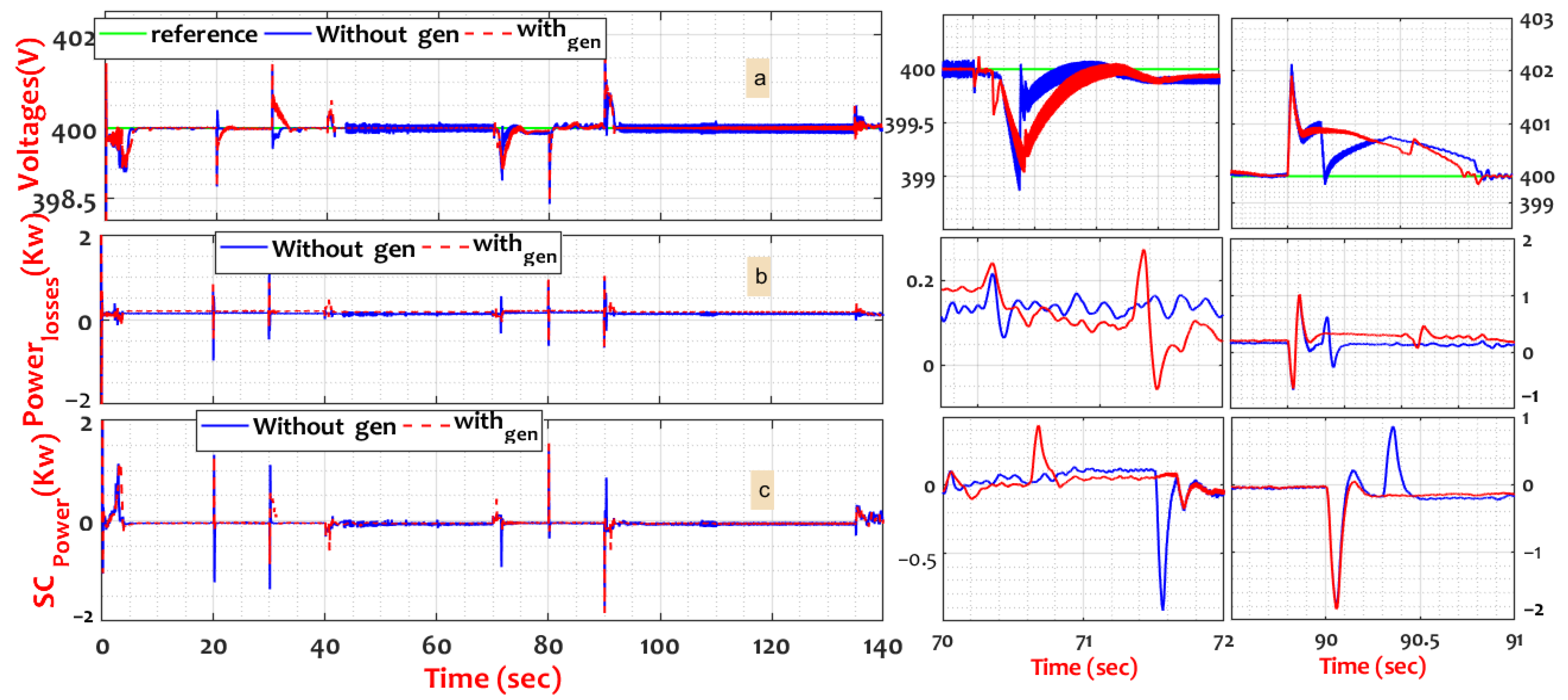
The stability of the HEV is depicted in Figure 15, where Figure 15a depicts the DC bus voltage during the proposed scenarios, where the HEV was stable without exceeding international standard thresholds ±5 (%) of the setpoint voltage of 400 (V).
Both topologies’ voltage response times are within acceptable 0.05 (s) limits. Figure 15a and zoom ones show that the ripple in the DC bus voltage while employing EV kinetic energy was much more smoothness than in the basic design, which had a value of roughly 0.03 (V). The max overtaking is less than 2 (V).
The immediate deformations are shown at 70 and 90 s (highlights 1 and 2), and others result from fast variation speed and implementation changes. Due to these deformations, the supercapacitor forced the system to act, as seen in Figure 15c. This immediate intervention ensured the required energy and the DC bus voltage stability.
When the EV speed rises to 70 (s), the SC intervention power in the basic topology is 0.8 (kW). However, the energy in the topology with a DC generator is only 0.2 kW. The end of the ramp is coordinated with a drop in speed at 90 (s), prompting the SC intervention by 0.8 (Kw) in both topologies with an increase of additional retrieval pulse in the basic topology. As a result, the HEV system remained stable for the entirety of the simulation in each topology.
Power deliberation naturally resulted in some power losses per the rule of power conservation. It is possible to trace it back to the energy losses of the analyzed model (as seen in the second subfigure). Due to the addition of sources, the system lost negligible energy losses compared to the quantity of energy obtained. Adding further power creates a loss proportional to the total amount of energy, which may be seen as a negative consequence of adding energy.
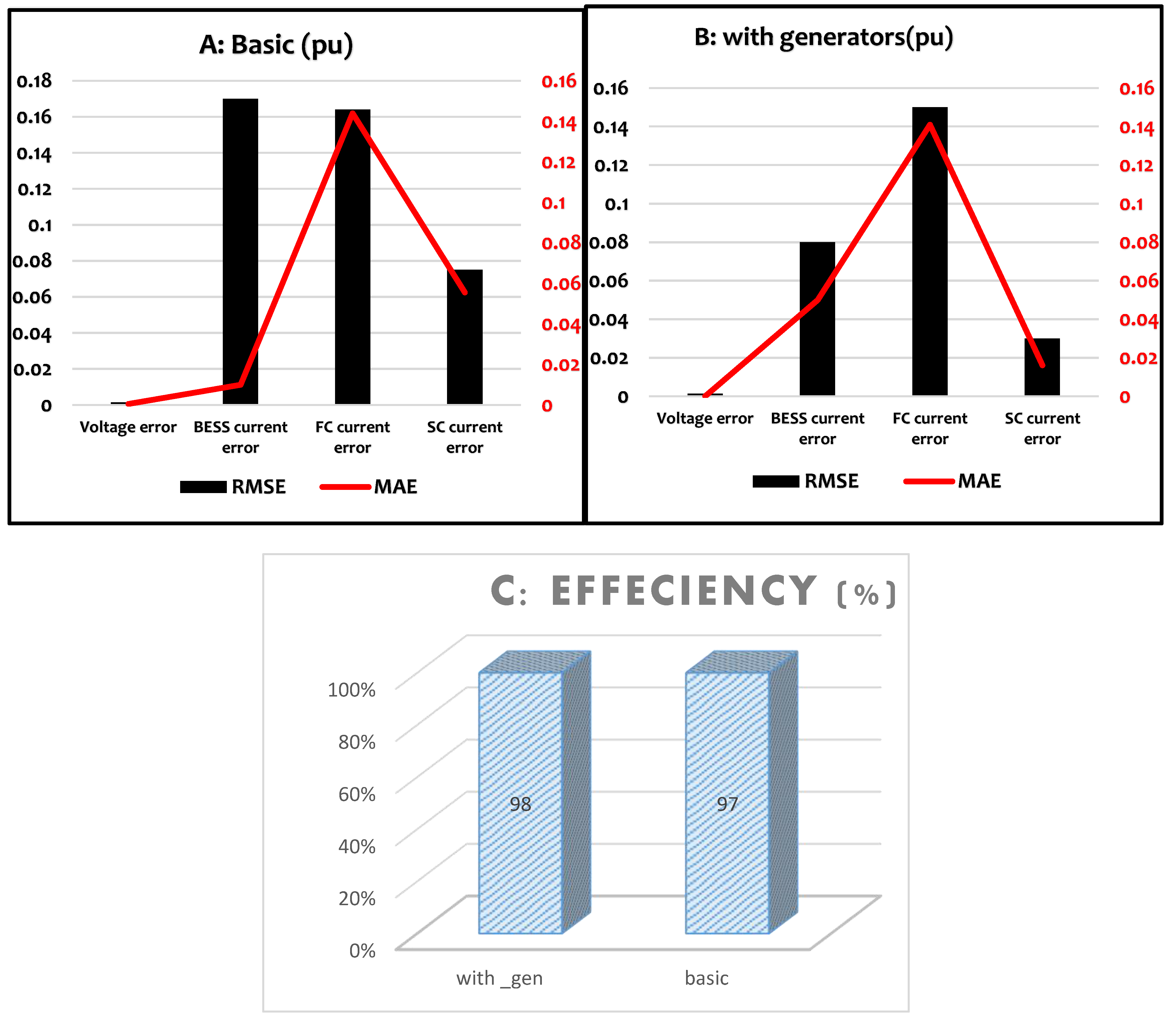
As shown in Figure 16, the power controller has demonstrated superior robustness in keeping the system tight and stable. Figure 16 illustrates how the controller handles errors brought about by the reference and measured values of the common converters used across the two topologies. This figure also demonstrates the global system’s efficiency.
These results included the DC bus voltage error, the control error of DC-DC BDC (current loop error), the FC control error, and the control error of SC’s BDC.
The results of the voltage control were the same (≈0.0013%), where the EV kinetic energy based on a robust controller (ST-SMC) increased the system’s performance. Compared to the basic topology, the strength of the current control increased by 53%, while the control of the FC boost converter was enhanced by 8%. As demonstrated in the same figure, the error control of the SC’s BDC has been improved by 60 (%).
Part c represents the efficiencies of the proposed topology and the basic topology. The EV kinetic energy improved the system’s efficiency due to the decrease in stress on the converters, which decreased losses and improved efficiency by 1 (%) compared to the efficiency of the basic topology.
Table 4 summarizes the results of improving the performance of the electric vehicle compared to the primary method. Comparison points include response time, efficiency, fuel consumption, and SOC with mechanical and energy control errors (RMSE, MAE), where the results show significant superiority of the proposed topology in most points.

5. Conclusions

Within the scope of this research, the enhancement of electric vehicle performances using DC generators and robust controllers was investigated. The proposed topologies have been investigated by simulating a 30-kW two-wheel drive electric vehicle while maintaining the same environmental and electrical management systems (EMS). The improved efficacy and robustness of the controllers can be seen in the stable behavior exhibited by the hybrid system across all possible topologies. The controllers have been refined. The suggested topology contributed to the exploitation of free energy by lowering the stress on the FC and BESS, which helped to maintain the useful life of the resources for an extended period. As a result of the HEV’s contribution to the reduction of fuel consumption, which in turn allowed for the saving of hydrogen as an economic consideration, the EV’s autonomy and running duration were extended by the HEV’s kinetic energy.
Finally, considering future prospects, the outstanding findings of kinetic energy exploitation employing robust controllers (speed controller and converters controller) are incentives for the experimental validation of the proposed HEV, besides applying EV’s kinetic energy in the optimization algorithms.

Author Contributions

Conceptualization, A.B.; Methodology, A.B.; Software, M.A.H.; Validation, M.A.H. and M.A.-D.; Formal analysis, H.T.; Investigation, H.T.; Resources, H.R.; Data curation, H.R.; Writing—original draft, A.B., M.A.H. and H.T.; Writing—review & editing, H.R. and M.A.-D.; Visualization, M.A.-D.; Supervision, M.A.-D. All authors have read and agreed to the published version of the manuscript.

Funding

This work was supported by the Interdisciplinary Research Center for Renewable Energy and Power Systems at King Fahd University of Petroleum and Minerals (KFUPM) under Project INRE2221.

Conflicts of Interest

The authors declare no conflict of interest.

Abbreviations

EMSsEnergy management strategies
HEVHybrid electric vehicle
FCFuel cell
DCDirect current
ACAlternative current
PIProportional-integral
SMState Machine
ANFISAdaptative neural fuzzy inference system
ANNArtificial neural network
SCSupercapacitor
2WDTwo-wheel drive
ESSEnergy storage system technology
PMDCGPermanent magnetic DC generator
KpProportional gain
KiIntegral gain
DTCDirect torque control
PevElectric vehicles power
PscSupercapacitor power
PbatBattery power
PfcFuel cell power
PDCgDC generators power
SVMSpace vector modulation
HESSHybrid energy storage system
HSHybrid system
BCVBattery constant voltage
DCGDirect current generator
BESSBattery energy storage system
KVLKirchhoff voltage law
KCLKirchhoff current law
BDCBidirectional converter
TFTransfer function
FBCFiltration-based control
HFHigh-frequency
LFLow-frequency
NOPNominal operating point
BDCBidirectional converter
SPSSimulink sim-power systems
MPPTMax power point tracker
NIMHNickel–metal hydride
SOCState of charge
HCCHybrid current control

References

  1. Song, Z.; Pan, Y.; Chen, H.; Zhang, T. Effects of Temperature on the Performance of Fuel Cell Hybrid Electric Vehicles: A Review. Appl. Energy 2021, 302, 117572. [Google Scholar] [CrossRef]
  2. Yin, W.; Qin, X.; Huang, Z. Optimal Dispatching of Large-Scale Electric Vehicles into Grid Based on Improved Second-Order Cone. Energy 2022, 254, 124346. [Google Scholar] [CrossRef]
  3. Hou, R.; Lei, L.; Jin, K.; Lin, X.; Xiao, L. Introducing Electric Vehicles? Impact of Network Effect on Profits and Social Welfare. Energy 2022, 243, 123002. [Google Scholar] [CrossRef]
  4. Wang, A.; Xu, J.; Zhang, M.; Zhai, Z.; Song, G.; Hatzopoulou, M. Emissions and Fuel Consumption of a Hybrid Electric Vehicle in Real-World Metropolitan Traffic Conditions. Appl. Energy 2022, 306, 118077. [Google Scholar] [CrossRef]
  5. Tian, X.; Cai, Y.; Sun, X.; Zhu, Z.; Xu, Y. A Novel Energy Management Strategy for Plug-in Hybrid Electric Buses Based on Model Predictive Control and Estimation of Distribution Algorithm. IEEE/ASME Trans. Mechatron. 2022, 27, 4350–4361. [Google Scholar] [CrossRef]
  6. Dong, H.; Fu, J.; Zhao, Z.; Liu, Q.; Li, Y.; Liu, J. A Comparative Study on the Energy Flow of a Conventional Gasoline-Powered Vehicle and a New Dual Clutch Parallel-Series Plug-in Hybrid Electric Vehicle under NEDC. Energy Convers. Manag. 2020, 218, 113019. [Google Scholar] [CrossRef]
  7. Soumeur, M.A.; Gasbaoui, B.; Abdelkhalek, O.; Ghouili, J.; Toumi, T.; Chakar, A. Comparative Study of Energy Management Strategies for Hybrid Proton Exchange Membrane Fuel Cell Four Wheel Drive Electric Vehicle. J. Power Sources 2020, 462, 228167. [Google Scholar] [CrossRef]
  8. Degradation Adaptive Energy Management Strategy Using Fuel Cell State-of-Health for Fuel Economy Improvement of Hybrid Electric Vehicle—ScienceDirect. Available online: https://www.sciencedirect.com/science/article/abs/pii/S0306261920317803 (accessed on 13 September 2022).
  9. Zhuang, W.; Li, S.; Zhang, X.; Kum, D.; Song, Z.; Yin, G.; Ju, F. A Survey of Powertrain Configuration Studies on Hybrid Electric Vehicles. Appl. Energy 2020, 262, 114553. [Google Scholar] [CrossRef]
  10. Habib, A.R.R.; Butler, K. Environmental and Economic Comparison of Hydrogen Fuel Cell and Battery Electric Vehicles. Future Technol. 2022, 1, 25–33. [Google Scholar] [CrossRef]
  11. Tanç, B.; Arat, H.T.; Conker, Ç.; Baltacioğlu, E.; Aydin, K. Energy Distribution Analyses of an Additional Traction Battery on Hydrogen Fuel Cell Hybrid Electric Vehicle. Int. J. Hydrogen Energy 2020, 45, 26344–26356. [Google Scholar] [CrossRef]
  12. Habib, A.R.R.; Butler, K. Alternatives to Lithium-Ion Batteries in Electric Vehicles. Future Technol. 2022, 1, 33–34. [Google Scholar] [CrossRef]
  13. Zhao, G.; Wang, X.; Negnevitsky, M.; Zhang, H. A Review of Air-Cooling Battery Thermal Management Systems for Electric and Hybrid Electric Vehicles. J. Power Sources 2021, 501, 230001. [Google Scholar] [CrossRef]
  14. Muzaffar, A.; Ahamed, M.B.; Deshmukh, K.; Thirumalai, J. A Review on Recent Advances in Hybrid Supercapacitors: Design, Fabrication and Applications. Renew. Sustain. Energy Rev. 2019, 101, 123–145. [Google Scholar] [CrossRef]
  15. Song, Z.; Liu, C. Electric Machine Design by a Novel Fast Model Predictive Optimization Strategy Treating Dimension-Expensive Problem; IEEE: Piscataway, NJ, USA, 2022; p. 1. [Google Scholar] [CrossRef]
  16. Tian, X.; Cai, Y.; Sun, X.; Zhu, Z.; Wang, Y.; Xu, Y. Incorporating Driving Style Recognition into MPC for Energy Management of Plug-In Hybrid Electric Buses. IEEE Trans. Transp. Electrif. 2023, 9, 169–181. [Google Scholar] [CrossRef]
  17. Benhammou, A.; Tedjini, H.; Guettaf, Y.; Soumeur, M.A.; Hartani, M.A.; Hafsi, O.; Benabdelkader, A. Exploitation of Vehicle’s Kinetic Energy in Power Management of Tow—Wheel Drive Electric Vehicles Based on ANFIS DTC-SVM Comparative Study. Int. J. Hydrogen Energy 2021, 46, 27758–27769. [Google Scholar] [CrossRef]
  18. Amine, H.M.; Mouaz, A.K.; Messaoud, H.; Othmane, A.; Saad, M. The Impacts of Control Systems on Hybrid Energy Storage Systems in Remote DC-Microgrid System: A Comparative Study between PI and Super Twisting Sliding Mode Controllers. J. Energy Storage 2022, 47, 103586. [Google Scholar] [CrossRef]
  19. Ammar, A.; Kheldoun, A.; Metidji, B.; Ameid, T.; Azzoug, Y. Feedback Linearization Based Sensorless Direct Torque Control Using Stator Flux MRAS-Sliding Mode Observer for Induction Motor Drive. ISA Trans. 2020, 98, 382–392. [Google Scholar] [CrossRef]
  20. Wang, Y.; Tian, J.; Sun, Z.; Wang, L.; Xu, R.; Li, M.; Chen, Z. A Comprehensive Review of Battery Modeling and State Estimation Approaches for Advanced Battery Management Systems. Renew. Sustain. Energy Rev. 2020, 131, 110015. [Google Scholar] [CrossRef]
  21. Wang, Y.; Wang, L.; Li, M.; Chen, Z. A Review of Key Issues for Control and Management in Battery and Ultra-Capacitor Hybrid Energy Storage Systems. eTransportation 2020, 4, 100064. [Google Scholar] [CrossRef]
  22. Meng, J.; Luo, G.; Ricco, M.; Swierczynski, M.; Stroe, D.-I.; Teodorescu, R. Overview of Lithium-Ion Battery Modeling Methods for State-of-Charge Estimation in Electrical Vehicles. Appl. Sci. 2018, 8, 659. [Google Scholar] [CrossRef] [Green Version]
  23. Hu, M.; Li, Y.; Li, S.; Fu, C.; Qin, D.; Li, Z. Lithium-Ion Battery Modeling and Parameter Identification Based on Fractional Theory. Energy 2018, 165, 153–163. [Google Scholar] [CrossRef]
  24. Wang, L.; Guo, J.; Xu, C.; Wu, T.; Lin, H. Hybrid Model Predictive Control Strategy of Supercapacitor Energy Storage System Based on Double Active Bridge. Energies 2019, 12, 2134. [Google Scholar] [CrossRef] [Green Version]
  25. Şahin, M.E.; Blaabjerg, F. A Hybrid PV-Battery/Supercapacitor System and a Basic Active Power Control Proposal in MATLAB/Simulink. Electronics 2020, 9, 129. [Google Scholar] [CrossRef] [Green Version]
  26. Zou, C.; Zhang, L.; Hu, X.; Wang, Z.; Wik, T.; Pecht, M. A Review of Fractional-Order Techniques Applied to Lithium-Ion Batteries, Lead-Acid Batteries, and Supercapacitors. J. Power Sources 2018, 390, 286–296. [Google Scholar] [CrossRef] [Green Version]
  27. Blal, M.; Benatiallah, A.; NeÇaibia, A.; Lachtar, S.; Sahouane, N.; Belasri, A. Contribution and Investigation to Compare Models Parameters of (PEMFC), Comprehensives Review of Fuel Cell Models and Their Degradation. Energy 2019, 168, 182–199. [Google Scholar] [CrossRef]
  28. Yue, M.; Jemei, S.; Gouriveau, R.; Zerhouni, N. Review on Health-Conscious Energy Management Strategies for Fuel Cell Hybrid Electric Vehicles: Degradation Models and Strategies. Int. J. Hydrogen Energy 2019, 44, 6844–6861. [Google Scholar] [CrossRef]
  29. Nanos, E.M.; Bottasso, C.L.; Campagnolo, F.; Mühle, F.; Letizia, S.; Iungo, G.V.; Rotea, M.A. Design, Steady Performance and Wake Characterization of a Scaled Wind Turbine with Pitch, Torque and Yaw Actuation. Wind. Energy Sci. 2022, 7, 1263–1287. [Google Scholar] [CrossRef]
  30. Brisset, S.; Radulescu, M. Design of a Brushless DC Permanent-Magnet Generator for Use in Micro-Wind Turbine Applications. Int. J. Appl. Electromagn. Mech. 2018, 56, 3–15. [Google Scholar]
  31. Laczko, A.A.; Brisset, S.; Radulescu, M. Modeling Approaches to Brushless DC Permanent-Magnet Generator for Use in Micro-Wind Turbine Applications; IEEE: Piscataway, NJ, USA, 2016; pp. 445–451. [Google Scholar]
  32. O’donnell, R.; Schofield, N.; Smith, A.C.; Cullen, J. Design Concepts for High-Voltage Variable-Capacitance DC Generators. IEEE Trans. Ind. Appl. 2009, 45, 1778–1784. [Google Scholar] [CrossRef]
  33. Do Dc Generators Offer Fuel Economy Advantages Over Ac Generators? Answers For The Telecom Industry |Cat| Caterpillar. Available online: https://www.cat.com/en_US/by-industry/electric-power/Articles/White-papers/answers-for-the-telecom-industry.html (accessed on 24 February 2023).
  34. Benchaib, A.; Rachid, A.; Audrezet, E. Sliding Mode Input-Output Linearization and Field Orientation for Real-Time Control of Induction Motors. IEEE Trans. Power Electron. 1999, 14, 3–13. [Google Scholar] [CrossRef]
  35. Yang, X.; Yao, J.; Deng, W. Output Feedback Adaptive Super-Twisting Sliding Mode Control of Hydraulic Systems with Disturbance Compensation. ISA Trans. 2021, 109, 175–185. [Google Scholar] [CrossRef] [PubMed]
  36. Ozdemir, S.; Altin, N.; Sefa, I.; Zhang, Z.; Komurcugil, H. Super Twisting Sliding Mode Control of Three-Phase Grid-Tied Neutral Point Clamped Inverters. ISA Trans. 2022, 125, 547–559. [Google Scholar] [CrossRef] [PubMed]
  37. Sellali, M.; Abdeddaim, S.; Betka, A.; Djerdir, A.; Drid, S.; Tiar, M. Fuzzy-Super Twisting Control Implementation of Battery/Super Capacitor for Electric Vehicles. ISA Trans. 2019, 95, 243–253. [Google Scholar] [CrossRef] [PubMed]
  38. Zhu, P.; Chen, Y.; Li, M.; Zhang, P.; Wan, Z. Fractional-Order Sliding Mode Position Tracking Control for Servo System with Disturbance. ISA Trans. 2020, 105, 269–277. [Google Scholar] [CrossRef]
  39. Suhail, M.; Akhtar, I.; Kirmani, S.; Jameel, M. Development of Progressive Fuzzy Logic and ANFIS Control for Energy Management of Plug-in Hybrid Electric Vehicle. IEEE Access 2021, 9, 62219–62231. [Google Scholar] [CrossRef]
  40. Elsisi, M.; Tran, M.-Q.; Mahmoud, K.; Lehtonen, M.; Darwish, M.M. Robust Design of ANFIS-Based Blade Pitch Controller for Wind Energy Conversion Systems against Wind Speed Fluctuations. IEEE Access 2021, 9, 37894–37904. [Google Scholar] [CrossRef]
  41. Kakodia, S.K.; Giribabu, D.; Ravula, R.K. Torque Ripple Minimization Using an Artificial Neural Network Based Speed Sensor Less Control of SVM-DTC Fed PMSM Drive; IEEE: Piscataway, NJ, USA, 2022; pp. 1–6. [Google Scholar]
  42. Space Vector Modulated—Direct Torque Controlled (DTC–SVM) Inverter—Fed Induction Motor Drive (Electrical/Electronics Project)|ProjectAbstracts.Com—Projects Ideas and Downloads. Available online: https://projectabstracts.com/6758/space-vector-modulated-direct-torque-controlled-dtc-svm-inverter-fed-induction-motor-drive.html (accessed on 29 August 2022).
  43. Mahmud, N.; Zahedi, A.; Mahmud, A. A Cooperative Operation of Novel PV Inverter Control Scheme and Storage Energy Management System Based on ANFIS for Voltage Regulation of Grid-Tied PV System. IEEE Trans. Ind. Inf. 2017, 13, 2657–2668. [Google Scholar] [CrossRef]
  44. Gupta, S.; Garg, R.; Singh, A. ANFIS-Based Control of Multi-Objective Grid Connected Inverter and Energy Management. J. Inst. Eng. India Ser. B 2020, 101, 1–14. [Google Scholar] [CrossRef]
  45. Song, K.; Li, F.; Hu, X.; He, L.; Niu, W.; Lu, S.; Zhang, T. Multi-Mode Energy Management Strategy for Fuel Cell Electric Vehicles Based on Driving Pattern Identification Using Learning Vector Quantization Neural Network Algorithm. J. Power Sources 2018, 389, 230–239. [Google Scholar] [CrossRef]
  46. Ammar, A.; Benakcha, A.; Bourek, A. Closed Loop Torque SVM-DTC Based on Robust Super Twisting Speed Controller for Induction Motor Drive with Efficiency Optimization. Int. J. Hydrogen Energy 2017, 42, 17940–17952. [Google Scholar] [CrossRef]
  47. Ferahtia, S.; Djeroui, A.; Rezk, H.; Houari, A.; Zeghlache, S.; Machmoum, M. Optimal Control and Implementation of Energy Management Strategy for a DC Microgrid. Energy 2022, 238, 121777. [Google Scholar] [CrossRef]
  48. Kraiem, H.; Flah, A.; Mohamed, N.; Alowaidi, M.; Bajaj, M.; Mishra, S.; Sharma, N.K.; Sharma, S.K. Increasing Electric Vehicle Autonomy Using a Photovoltaic System Controlled by Particle Swarm Optimization. IEEE Access 2021, 9, 72040–72054. [Google Scholar] [CrossRef]
  49. Yildiz, A.; Özel, M.A. A Comparative Study of Energy Consumption and Recovery of Autonomous Fuel-Cell Hydrogen–Electric Vehicles Using Different Powertrains Based on Regenerative Braking and Electronic Stability Control System. Appl. Sci. 2021, 11, 2515. [Google Scholar] [CrossRef]
  50. Sorlei, I.-S.; Bizon, N.; Thounthong, P.; Varlam, M.; Carcadea, E.; Culcer, M.; Iliescu, M.; Raceanu, M. Fuel Cell Electric Vehicles—A Brief Review of Current Topologies and Energy Management Strategies. Energies 2021, 14, 252. [Google Scholar] [CrossRef]
  51. Lee, U.; Jeon, S.; Lee, I. Design for Shared Autonomous Vehicle (SAV) System Employing Electrified Vehicles: Comparison of Battery Electric Vehicles (BEVs) and Fuel Cell Electric Vehicles (FCEVs). Clean. Eng. Technol. 2022, 8, 100505. [Google Scholar] [CrossRef]
  52. Ramadan, H.S.; Hassan, I.A.; Alhelou, H.H. Robust Control for Techno-economic Efficient Energy Management of Fuel Cell Hybrid Electric Vehicles. IET Renew. Power Gener. 2022, 16, 661–1684. [Google Scholar] [CrossRef]
  53. Mounica, V.; Obulesu, Y. Hybrid Power Management Strategy with Fuel Cell, Battery, and Supercapacitor for Fuel Economy in Hybrid Electric Vehicle Application. Energies 2022, 15, 4185. [Google Scholar] [CrossRef]
  54. Salem, M.; Elnaggar, M.; Saad, M.S.; Fattah, H.A.A. Energy Management System for Fuel Cell-Battery Vehicles Using Multi Objective Online Optimization. IEEE Access 2022, 10, 40629–40641. [Google Scholar] [CrossRef]
  55. Cunanan, C.; Tran, M.-K.; Lee, Y.; Kwok, S.; Leung, V.; Fowler, M. A Review of Heavy-Duty Vehicle Powertrain Technologies: Diesel Engine Vehicles, Battery Electric Vehicles, and Hydrogen Fuel Cell Electric Vehicles. Clean Technol. 2021, 3, 474–489. [Google Scholar] [CrossRef]
  56. İnci, M.; Büyük, M.; Demir, M.H.; İlbey, G. A Review and Research on Fuel Cell Electric Vehicles: Topologies, Power Electronic Converters, Energy Management Methods, Technical Challenges, Marketing and Future Aspects. Renew. Sustain. Energy Rev. 2021, 137, 110648. [Google Scholar] [CrossRef]
  57. Carello, M.; de Carvalho Pinheiro, H.; Longega, L.; Di Napoli, L. Design and Modelling of the Powertrain of a Hybrid Fuel Cell Electric Vehicle. SAE Int. J. Adv. Curr. Pract. Mobil 2021, 3, 2878–2892. [Google Scholar]
  58. Zhou, Y.; Ravey, A.; Péra, M.-C. Real-Time Cost-Minimization Power-Allocating Strategy via Model Predictive Control for Fuel Cell Hybrid Electric Vehicles. Energy Convers. Manag. 2021, 229, 113721. [Google Scholar] [CrossRef]
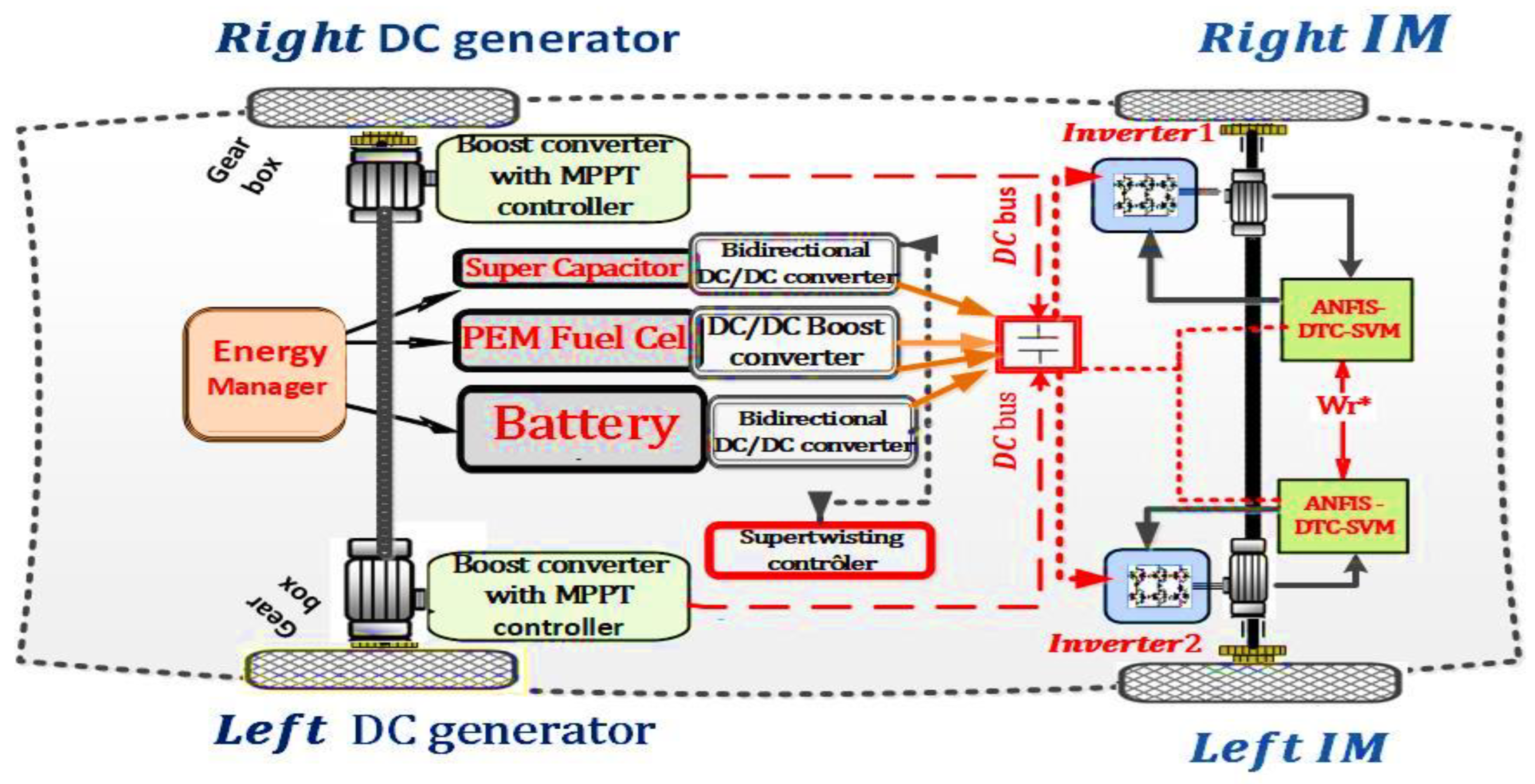
Figure 1. The proposed EV model under study. The term wr* denotes the reference speed value of the EV.
Sustainability 15 05657 g001
Figure 2. BESS mathematical model. Where E0 is the BCV, K is polarization constant V/(Ah), Q is battery capacity (Ah), i* battery filtered current, Ab is exponential zone amplitude, B is exponential zone time constant inverse, Rb is battery internal resistance, and Polres is Polarization resistance, it is the actual battery charge (Ah).
Sustainability 15 05657 g002
Figure 3. The descriptive model of SC. Where Ne is the number of electrode layers, ε & ε0 are the permittivities (F/m) of the electrolyte material and free space, Ai is the interfacial area (m2), D is the Helmholtz layer length (m), Qc is the cell electric charge (C), C is the molar concentration (mol m−3). Np, NS, Ne cells number, QT is the total electric charge (C), is supercapacitor module resistance (Ω), and iSC is supercapacitor module current (A).
Sustainability 15 05657 g003
Figure 4. The descriptive model of FC. Where Vfc is fuel cell output voltage, I0 is the exchange current (A), Ufh2, Ufo2 are hydrogen and oxygen utilization, Pfuel, Pair are supply pressures of fuel and air (atm), x and y are percentages of hydrogen and oxygen, Vfc and Vair are fuel and air-flow rates (l/min), ifc is cell current (A), Ph2 and Po2 are hydrogen and oxygen partial pressures (atm), T is operating temperature (K), F is Faraday constant (A s/mol), R is ideal gas constant (J/mol K), K is voltage constant, E0 is cell open circuit voltage, En is thermodynamic voltage, Ku is voltage undershoots. Ufo2n is nominal oxygen utilization (%), N is the number of cells, Td is cell settling time to a current step, α is the charge transfer coefficient, ΔG is activation energy barrier (J), K is Boltzmann constant (J/K), h is Planck constant (J s).
Sustainability 15 05657 g004
Figure 5. The DC generator model is connected to the HEV wheel. Va and Ia are PMDCG output voltage and current, Pa is PMDCG output current, and E is electromotive force.
Sustainability 15 05657 g005
Figure 6. Circuits and control structures of the HESS batteries: (a) DC-DC converters, (b) bidirectional control unit based on ST-SMC. where: VDC is dc voltage, isc is supercapacitor current, I HESS is total system current, I BESS battery current, Vsc is supercapacitor voltage, VBESS battery voltage, e is for errors, (*) reference value and (s1, s2,….s4) are switches control.
Sustainability 15 05657 g006
Figure 7. The standard structure of the super-twisting controller.
Sustainability 15 05657 g007
Figure 8. ANFIS DTC SVM control: (a) structure and design of ANFIS-DTC-SVM, (b) ANFIS unit design and inputs membership functions.
Sustainability 15 05657 g008
Figure 9. Diagram of space vector voltage and duty cycle for the sector 1: (a) voltage positions, (b) vectors duration.
Sustainability 15 05657 g009
Figure 10. The proposed SM-EMS rules.
Sustainability 15 05657 g010
Figure 11. Explanation schematic of the relationship between autonomy and stress. The EV goes the distance of D (km) with significant stress on the sources in basic topology. In contrast, the same EV goes after improving the distance of D + d (km), reducing stress on the sources, thus improving the studied system’s independence.
Sustainability 15 05657 g011
Figure 12. Basic measurements of the electric motor on which the EV is based: (a) speed and torque, (b) current, and (c) flux waveforms of wheels drive.
Sustainability 15 05657 g012
Figure 13. The power balance profiles of the proposed HEV: (a) without DC generators and (b) with a generator.
Sustainability 15 05657 g013
Figure 14. Operating behavior of BESS and FC under the proposed scenarios: (a) BESS power, (b) FC power, (c) BESS stress, (d) FC stress, (e) BESS’s state of charge, and (f) fuel consumption.
Sustainability 15 05657 g014
Figure 15. HEV voltage stability during transient and steady-state proposed scenarios: (a) DC bus voltage of each topology, (b) power losses of each topology, and (c) SC behavior of each topology.
Sustainability 15 05657 g015
Figure 16. The HEV performance evaluation using KPIs indexes: (A) errors control in the basic topology (without generators), (B) errors control using DC generators and (C) efficiency of the system in the proposed topologies.
Sustainability 15 05657 g016
Table 1. Vehicle system specification.
TypeParametersValue
Vehiclefr0.0135
rt (m)0.31
cd0.32
ρair (kg/m3)1.108
A (m2)2.63
Motors power (kW)30
Fuel cellVoltage (v)200
MOP and NOP (A, V)150,200 and 40,200
Number of cells285
Supply pressure h2 (bar)1.5
Efficiency (%)55
Composition: H2O, H2, O2 (%)1, 99.95, 21
DC generatorArmature resistance Ra (Ω)0.8727
Power (kW)3
La (H)0.001882
Tem (N.m)4.2
Battery packCapacity (Ah)20
Nominal voltage (V)200
Fully charged (V)230
SC bankRated voltage200
Internal resistance (Ω)2.10−4
Rated capacitance (F)14.6
Table 2. Cycles of SVM outputs.
Sector123456
SaTbTaTaTcTbTc
SbTaTcTbTbTcTa
ScTcTbTcTaTaTb
Table 3. The running scenario of HEV for simulation tests.
State PeriodExplanation
1[0, 40]The HEV’s reference speed is 90 km/h using a ramp of (11°) [20–30] (s).
2[40, 70]The HEV’s speed is 60 km/h.
3[70, 90]The HEV runs at 100 km/h, applying the slope of 12° from 80 to 90 (s).
4[90, 135]The HEV’s speed dropped to 60 km/h, detoured 30° on the left.
5[135, 140]The vehicle stopped during this period.
Table 4. Comparison of the HEV performance using the proposed topologies.
HEV Scenarioswith DC GeneratorsBasic HEV
Criteria
Response time (s)0.050.05
Efficiency (%)9897
SOC (%)60.1–59.760.1–59.52
Fuel consumption (SI)15.0724.78
Stress (%)
BESS 4162
FC2938
DC bus voltage (V)
RMSE (%)0.00130.0014
MAE (%)0.000050.0047
Battery current control error (A)
RMSE (%)0.0380.17
MAE (%)0.0250.01
FC current control error (%)
RMSE (%)0.150.164
MAE (%)0.1410.144
SC current control error (A)
RMSE (%)0.0040.075
MAE (%)0.00370.055
HEV speed control error (%)
RMSE (%)0.40.4
MAE (%)0.170.17
HEV torque control error (%)
RMSE (%)0.590.59
MAE (%)0.240.24
Disclaimer/Publisher’s Note: The statements, opinions and data contained in all publications are solely those of the individual author(s) and contributor(s) and not of MDPI and/or the editor(s). MDPI and/or the editor(s) disclaim responsibility for any injury to people or property resulting from any ideas, methods, instructions or products referred to in the content.