Article

Calculation Theory of Counterweight Double-Row Pile Support for Deep Foundation Pit in Reclamation Area and Influence Analysis of Core Pile Parameters

1
School of Mechanics and Engineering, Liaoning Technical University, Fuxin 123000, China
2
College of Architecture and Engineering, Dalian University, Dalian 116622, China
3
Shenzhen Dasheng Surveying Technology Co., Shenzhen 518000, China
*
Author to whom correspondence should be addressed.
Sustainability 2023, 15(7), 6184; https://doi.org/10.3390/su15076184
Submission received: 7 February 2023 / Revised: 8 March 2023 / Accepted: 27 March 2023 / Published: 4 April 2023

Abstract

:
The theoretical calculation of a counterweight double-row pile supporting structure is deduced and studied in this paper. The derived calculation method is applied to a Midas GTS NX simulation calculation. A case study of a deep foundation pit project in Shenzhen City is used to verify and analyze the simulation results and the field monitoring results. On this basis, the influence law of deformation parameters such as the row distance, pile diameter of back-row piles and load of the pit top on the pile of a double-row pile is further discussed. The results show that both the front- and back-row piles of counterweight double-row piles are overturning deformation, and the characteristics of the horizontal displacement are basically the same. The maximum value of the horizontal displacement of the pile is at the top and the minimum value is at the bottom. With the increase in the row distance and pile diameter, the horizontal displacement of the pile becomes smaller, and the change in the pile horizontal displacement under a top load is contrary to that. Moreover, the change in the row distance has a great influence on the horizontal displacement of the pile, followed by the load of the pit top, and the pile diameter of the back-row piles has the least influence. Due to the connection effect of the horizontal plate of the counterweight platform, the whole supporting structure is in the form of a hyperstatic structure. The back-row piles can withstand most of the lateral earth pressure, which effectively reduces the deformation of the front pile and improves the overall stiffness of the supporting structure, which is conducive to the excavation stability of the deep foundation pit. Therefore, its extensive use in the Linhai soft soil project can not only effectively reduce the number of internal supports and achieve the purpose of cost saving but also increase the construction face, which is beneficial to the development of dry construction organization and management, in line with the construction concept of green environmental protection and sustainable development advocated at present.

1. Introduction

With the acceleration of urban modernization, China has become a veritable country of the exploitation and utilization of underground space. The volume of foundation pit engineering continues to increase due to the construction needs of underground rail transit dominated by the subway and underground municipal engineering dominated by a comprehensive pipe gallery. The existing supporting structures such as a soil nailing wall, pile anchor support, fish-belly internal support and double-row pile [1] are often unable to support the foundation pit in the face of a complex building environment and special geological conditions, especially the increasingly strict deformation control standards of a deep foundation pit in urban soft soil areas.
A theoretical analysis, model test, field monitoring and numerical simulation have been reported on the study of a pile row supporting structure. Some of them derive a series of calculation formulas and establish a calculation model. Even the structure form of a pile row, the failure mechanism of the pile body and the distribution law of earth pressure have been studied in depth [2,3,4,5,6]. In general, a laboratory model test and an in situ test are used to study the deformation characteristics and stability mechanism of row piles in the process of foundation pit construction. The earth pressure, bending moment and displacement of piles under different strata, dip angle, row spacing and other influencing factors were analyzed to verify the feasibility and correctness of the pile row theory [7,8,9,10,11].
With the rapid development of numerical simulation technology, it is possible to establish a three-dimensional solid model of pile row support for a deep foundation pit. By comparing the field monitoring data with the simulation results and inversion, the spatio-temporal variation law of pile deformation with the excavation of a foundation pit can be well obtained, and then the influence on the surrounding environment can be evaluated. This provides important theoretical guidance for scientific construction and precise prevention and control [12,13,14,15,16,17]. The convenience of the simulation calculation provides technical support for further exploring the influence of soil factors such as the elastic modulus, cohesion and internal friction angle on a pile row system [18]. This makes it possible to optimize and adjust design parameters, such as the pile spacing, number, buried length and pile type [19,20,21,22], and especially a sensitivity analysis under the interaction of multiple factors [23,24,25].
A double-row pile supporting structure overcomes the problem of a narrow construction site and has the advantages of large overall stiffness, less anchor cable installation, convenient construction and so on, so it is used in deep foundation pit supporting engineering. Zhou et al. [26,27,28,29] conducted an in-depth study and summarized the existing problems and shortcomings of the calculation theory and model tests in the reported studies on double-row piles, including the pile failure mechanism, soil pressure distribution law and structural form.
Shen and Gu et al. used finite element software to analyze the influence of the pile top connection on the lateral displacement and internal force distribution of double-row piles [19,20]. Wang and Zhou et al. explored the variation rule of parameters such as the length-width ratio, excavation depth, row spacing and pile diameter on the soil pressure, pile lateral deformation and bending moment around the pile and used PLAXIS3D software [21,22] to study the differences in the pile forces at different positions around the foundation pit. Liu et al. [30] studied the influence of factors such as the pile spacing, row spacing of front and back piles and pile length on the overall stiffness and stability of a double-row pile supporting structure by using the control variable method.
However, the research on the mechanism and influencing factors of counterweight double-row pile supporting structures is quite limited. Therefore, the calculation model of a counterweight double-row pile is derived based on the Rankine earth pressure theory and earth arch principle. On this basis, combined with the field monitoring results of a deep foundation pit project in Shenzhen (China), the influence rule of the row distance, pile diameter of back-row piles and load adjustment of the pit top on the deformation of the counterweight double-row pile was analyzed by a numerical simulation and using Midas GTS_NX finite element software.

2. Background

2.1. Engineering Situation

The foundation pit supporting project is located in the south of a subway station in Nanshan District, Shenzhen. The total excavation area is about 30,435 m2, the maximum excavation depth is 11.2 m and the excavation is carried out in three layers from the south pit top to the bottom of the pit. The project site belongs to the reclamation area, the terrain is relatively flat and the strata are mainly distributed from top to bottom: stone filling, silt, silty clay, gravel clay, fully weathered granite and strongly weathered granite. According to the geotechnical test report, the design parameters of each soil layer in the foundation pit are shown in Table 1.

2.2. The Design Scheme of Pile Row

The double-row pile is a whole formed by the rigid connection of the upper L-shaped weighing platform and the lower two rows of piles. The L-shaped weighing platform is composed of the horizontal plate and the side retaining plate of the weighing platform. The width of the horizontal plate of the weighing platform is 5.4 m; the thickness is 0.5 m; the height of the vertical side plate is 2.7 m; and the thickness is 0.3 m. The distance between the front and back rows of the double-row piles is 3.6 m, the front-row piles are occlusal piles, the back-row piles are cast-in piles and the pile diameters of both the front and back rows are 1.2 m. It is worth mentioning that the length of the front- and back-row piles is different; the front pile is 24 m, and the back-row pile is 26 m long, as shown in Figure 1.

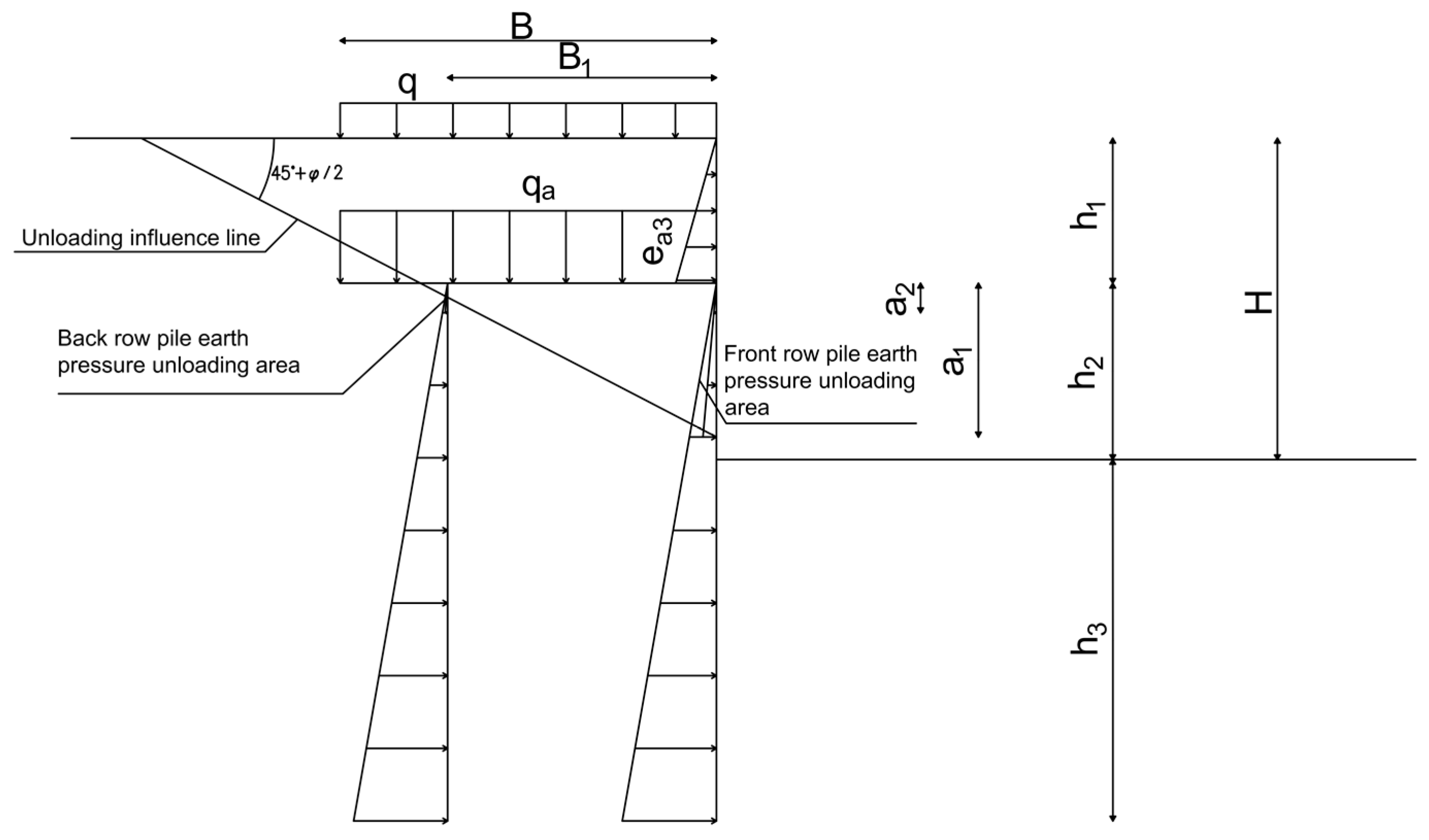
3. Design Theory Analysis of Counterweight Double-Row Pile

3.1. Calculation Model

The calculation model of counterweight double-row pile is based on Rankine earth pressure theory and earth arch principle and obtained by analyzing the active earth pressure. In addition, the model also refers to the results of Gu et al. [1] and Hu et al. [31] on the mechanical characteristics of counterweight pile plate retaining wall. The force calculation diagram of the model is shown in Figure 2.
To simplify the soil pressure analysis, the soil inside and outside the foundation pit is assumed to be homogeneous. The depth of the foundation pit is H, the buried depth of the horizontal slab of the weighing platform is h1, the cantilever height of the front- and back-row piles is h2, the embedment depth of the front- or back-row piles is h3, the width of the horizontal slab of the weighing platform is B and the row distance of the front- and back-row piles is B1. The angle of influence line of unloading horizontal plate of weighing platform is α = 45° + φ/2 (φ is the internal friction angle of soil), as shown in Figure 2.
When there is no additional load at the top, the soil side pressure ea3 of the retaining plate at the side of L-shaped weighing platform presents a triangular distribution with the increase in depth. If there is additional uniform live load q at the top of the foundation pit, then the lateral soil pressure presents a trapezoidal distribution with the increase in depth. Based on Rankine’s earth pressure theory, its calculation equation is as follows:
e a 3 = ( q + γ h ) K a   ,   h [ 0 , h 1 ]
where Ka is the earth pressure coefficient on the active side; γ is the soil weight.
The vertical pressure caused by soil in the upper part of the horizontal slab of the counterweight platform is qd, and the live load q is added to the top of the foundation pit. The total vertical distribution force borne by the horizontal plate of the weighing platform is qa, which has the following relationship:
q a = q d + q = γ h 1 + q
According to Rankine earth pressure principle and earth arch principle, the additional horizontal load borne by the front pile is
e q 1 = q a K a η 2
Accordingly, the additional horizontal load borne by the back-row piles is
e q 2 = q a K a ( 1 η 2 )
where η2 is the proportional coefficient of the lateral horizontal earth pressure transferred directly to the front row, which can be calculated by the following equation:
η 2 = { 1 ( b 0 s 2 ) s max < s 2 0 s max s 2
where S2 is the spacing of piles in the back row; Smax is the maximum distance between soil arches; b0 is the horizontal influence width of the back-row piles barrier. The values of these parameters are calculated according to the current national standard foundation pit procedure (JGJ120).
The starting depth of additional horizontal load of front- or back-row piles is calculated as follows (take the bottom of horizontal plate of weighing platform as zero point, see Figure 2):
a 1 = B tan α
a 2 = ( B B 1 ) tan α
α = 45 ° + ϕ / 2
Therefore, the total soil lateral pressure strength under the horizontal plate of the weighing platform is
e a = γ h K a   ,   h [ 0 , h 2 + h 3 ]
It must be noted that the bottom of the horizontal plate of the weighing platform is h = 0, that is, the starting point of earth pressure.
The soil lateral pressure strength of the front- and back-row piles caused by the soil under the horizontal plate of the weighing platform can be calculated according to the following equation (see Figure 1):
e a 1 = e a η
e a 2 = e a ( 1 η )
where ea is Rankine active earth pressure strength; η is the soil pressure distribution coefficient of front- or back-row piles.
By combining Equations (4)–(11), the soil lateral pressure strength of the front- and back-row piles after integrated calculation can be written as
e a 1 = { e a 1       [ 0       a 1 ] e q 1 + e a 1                   [ a 1                       h 2 + h 3 ]
e a 2 = { e a 2                     [ 0         a 2 ] e q 2 + e a 2                       [ a 2                 h 2 + h 3 ]
where ea1 is the active earth pressure strength assigned by the front pile; ea2 is the active earth pressure strength assigned by the back-row piles.

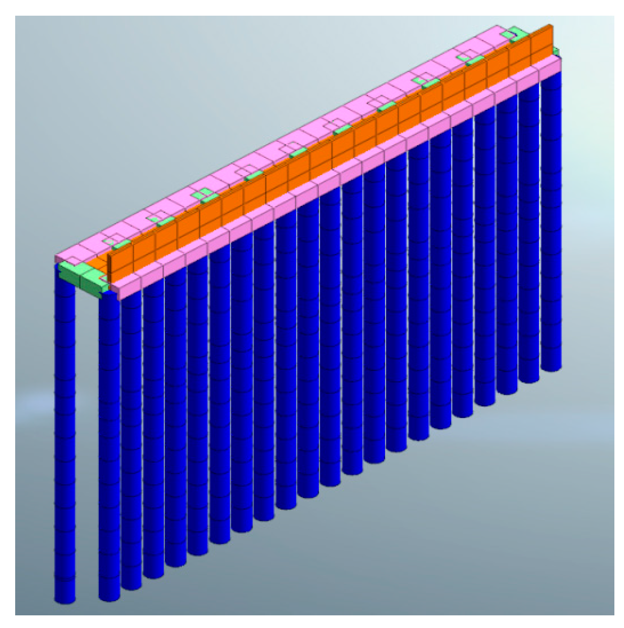
3.2. Model Construction and Parameter Selection

The finite element software Midas GTS is used to simulate and calculate the stability of the foundation pit. Considering the regular shape of the foundation pit in this project, only one side of the foundation pit is modeled in order to simplify the model. The size of the model is 72 m × 36 m × 54 m (X × Y × Z), and the key construction stage of foundation pit excavation is selected as the criterion to analyze the deformation and stress law of the counterweight double-row pile. It is assumed that all soil layers are isotropic ideal elastoplastic bodies, and the retaining piles, crown beams and joint beams are linear elastomers, which conform to the modified Mohr–Coulomb yield criterion. The soil layer is simulated by three-dimensional solid, the front- and back-row piles are simulated by implantable beam element, the balance plate and baffle are simulated by plane plate element and the crown beam and connecting beam of the foundation pit are simulated by one-dimensional beam element. An additional load of 20 kPa is considered at the top of the foundation pit. The model is shown in Figure 3 and Figure 4.

4. Results and Discussion

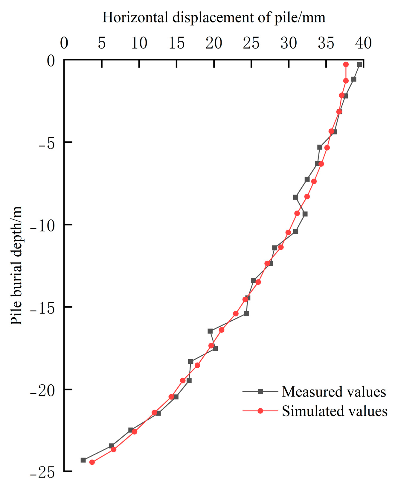
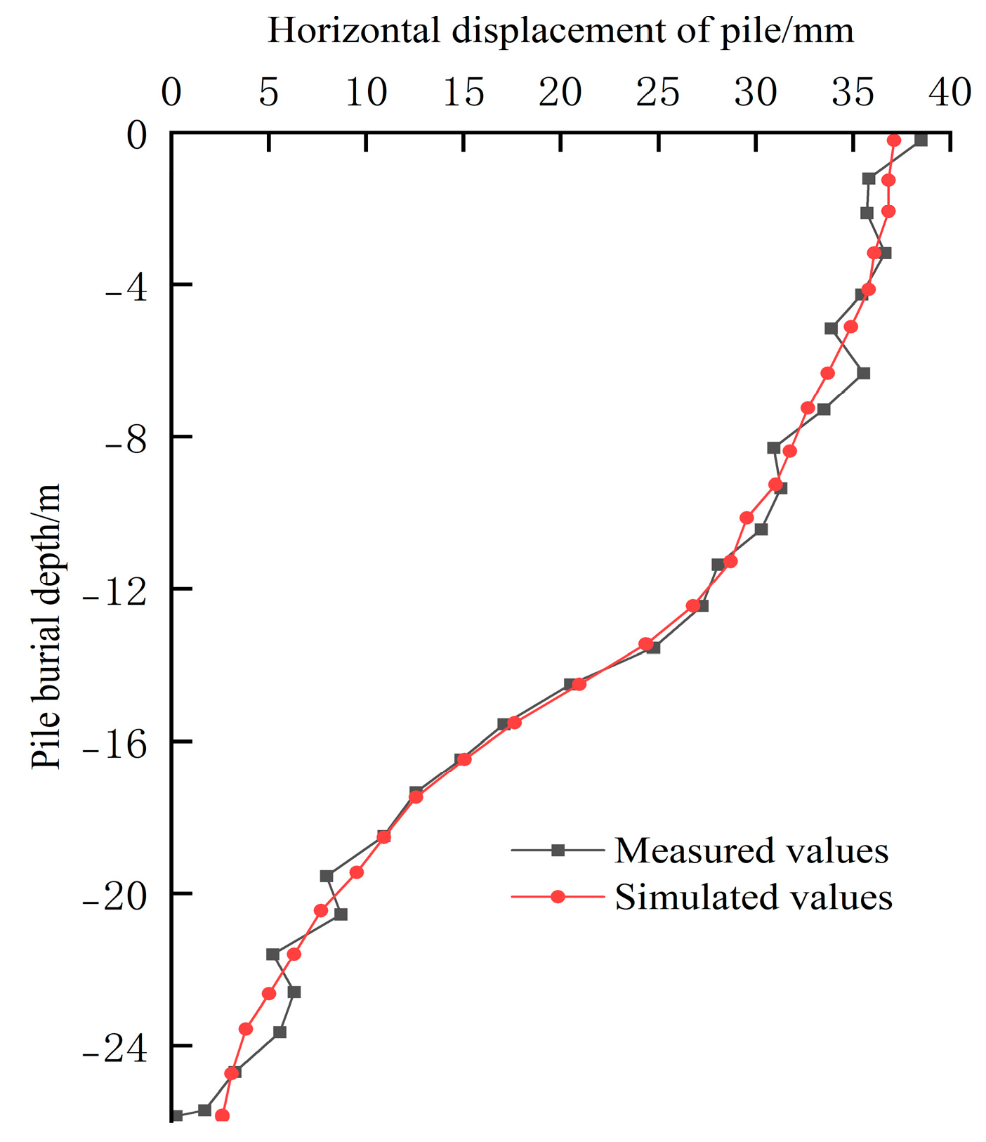
4.1. Comparative Analysis of Simulation Results and Monitoring Data

A series of reinforcement stress meters were embedded in advance to monitor the bending moment of the pile body (as shown in Figure 5). The total station is used to monitor the pile displacement on site (as shown in Figure 6). All the monitoring data were collated and compared with the numerical simulation results to verify the correctness of the numerical simulation results.

4.1.1. Comparison of Horizontal Displacement of Pile

The horizontal displacements of the front- and back-row piles after the completion of the foundation pit excavation are shown in Figure 7 and Figure 8. As can be seen, the simulated horizontal displacement values of the front- and back-row piles of the counterweight double-row pile are basically consistent with the overall trend of the field monitoring values. The maximum horizontal displacement of both piles is located at the pile top. Possibly affected by the site construction environment, the measured values are all slightly larger than the finite element simulation values, in which the maximum horizontal displacement of the front pile is 39.8 mm, 2.8 mm larger than the simulation value. The maximum horizontal displacement of the back-row piles is 38.2 mm, which is 1.8 mm larger than the simulated value. Obviously, the horizontal deformation of the front pile top should be emphasized to ensure the stability of the foundation pit supporting structure in the construction process.
In addition, due to the connection effect of the horizontal plate of the weighing platform, the front- and back-row piles can bear the lateral soil pressure evenly, and the maximum horizontal displacement of the pile body is 37 mm and 36.4 mm, respectively. The deformation trend of the two above the bottom of the foundation pit is the same as the whole, and the distribution is in the shape of a “convex curve”. The difference is that the inflection point of the horizontal displacement of the back-row pile occurs at −1 m under the foundation pit due to the limitation of the passive side earth pressure, and the growth rate of the horizontal displacement has an obvious decreasing trend compared with that of the front-row pile due to the influence of the embedment depth.

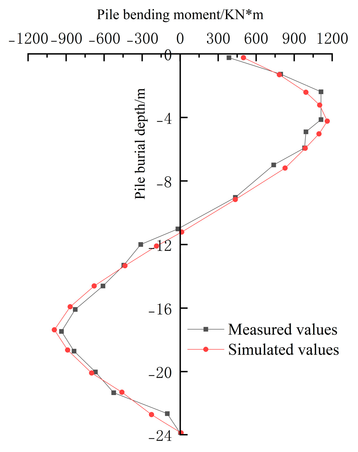
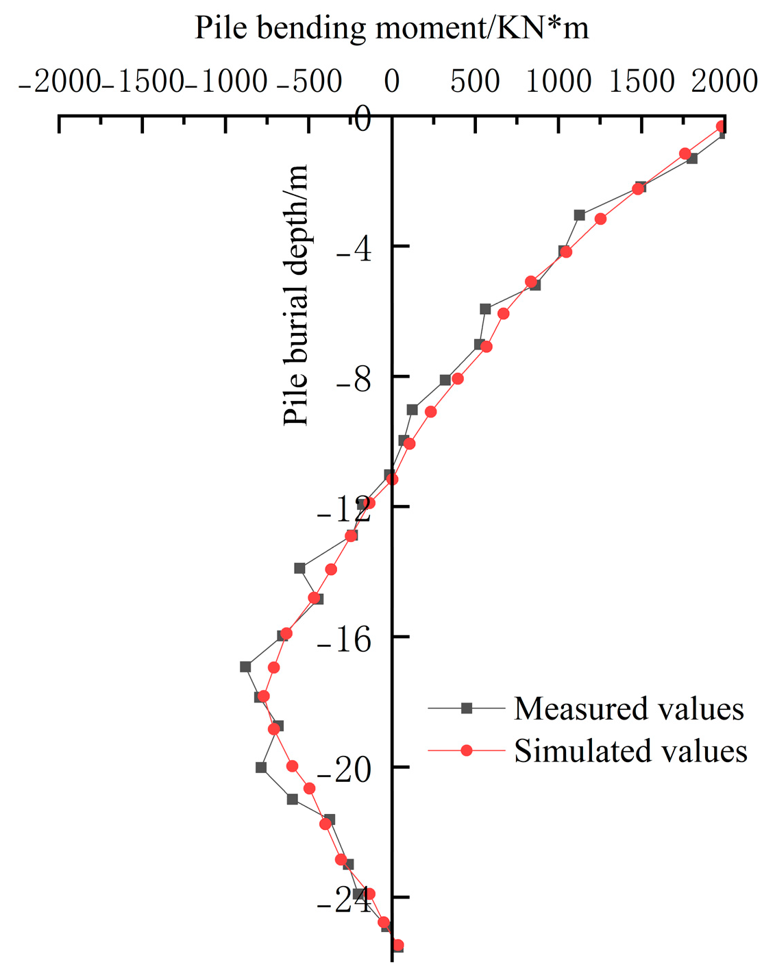
4.1.2. Comparative of Pile Bending Moment Value

It can be seen from Figure 9 and Figure 10 that the numerical simulation values of the front and back bending moments of the counterweight double-row piles show the same overall trend as the field monitoring values, and the maximum positions of the positive and negative bending moments are similar. The measured maximum positive bending moment of the front pile is 1105.5 kN·m, and the simulated value is 1180.3 kN·m. The measured maximum negative bending moment is −1150.4 kN·m, and the simulated value is −1190.2 kN·m. The measured bending moment values are all smaller than the finite element simulation values. The maximum positive bending moment of the back-row piles is located at the top of the pile, and the value is close to that of the pile. The measured maximum negative bending moment is −1050.06 kN·m, the simulated value is −999.3 kN·m, and the measured value is greater than the simulated value.
In addition, due to the connection of the horizontal plate of the weighing platform, the pile in the back (1998 kN·m) bears a greater bending moment at the pile top position than the pile in the front (1180.3 kN·m). Of course, this also helps the front pile to resist the lateral deformation of the foundation pit, and the reverse bending point of the front- and back-row piles is about 11 m from the pile body. This shows that the overall stiffness of the counterweight double-row supporting structure is indeed good, and it has a good effect on controlling the deformation of the excavation stage and the stability of the foundation pit during the later construction period.

4.2. The Effect Analysis of Pile Parameters

The front- and back-row piles are connected by the upper rigid L-shaped weighing platform to form a hyperstatic structure in space, which significantly improves the horizontal stiffness and anti-deformation ability of the structure. In addition, the L-shaped weighing platform also plays a role in coordinating the bending moment and shear force of the front- and back-row piles, which makes the internal force distribution of the supporting piles more uniform and reasonable. However, the mechanical mechanism of the pile in the front and back of the double-row pile is complex, and there are many adjustable parameters of the structure size, such as the row distance, buried depth of the horizontal plate of the weighing platform, width of the horizontal plate of the weighing platform, etc. Each parameter adjustment may have a great influence on the mechanical deformation of the whole structure; therefore, it is necessary to study the influence law of the adjustable parameters on the structure deformation, to provide a certain reference for the structure design. The parameter analysis scheme was formulated according to the current design specification, as shown in Table 2.

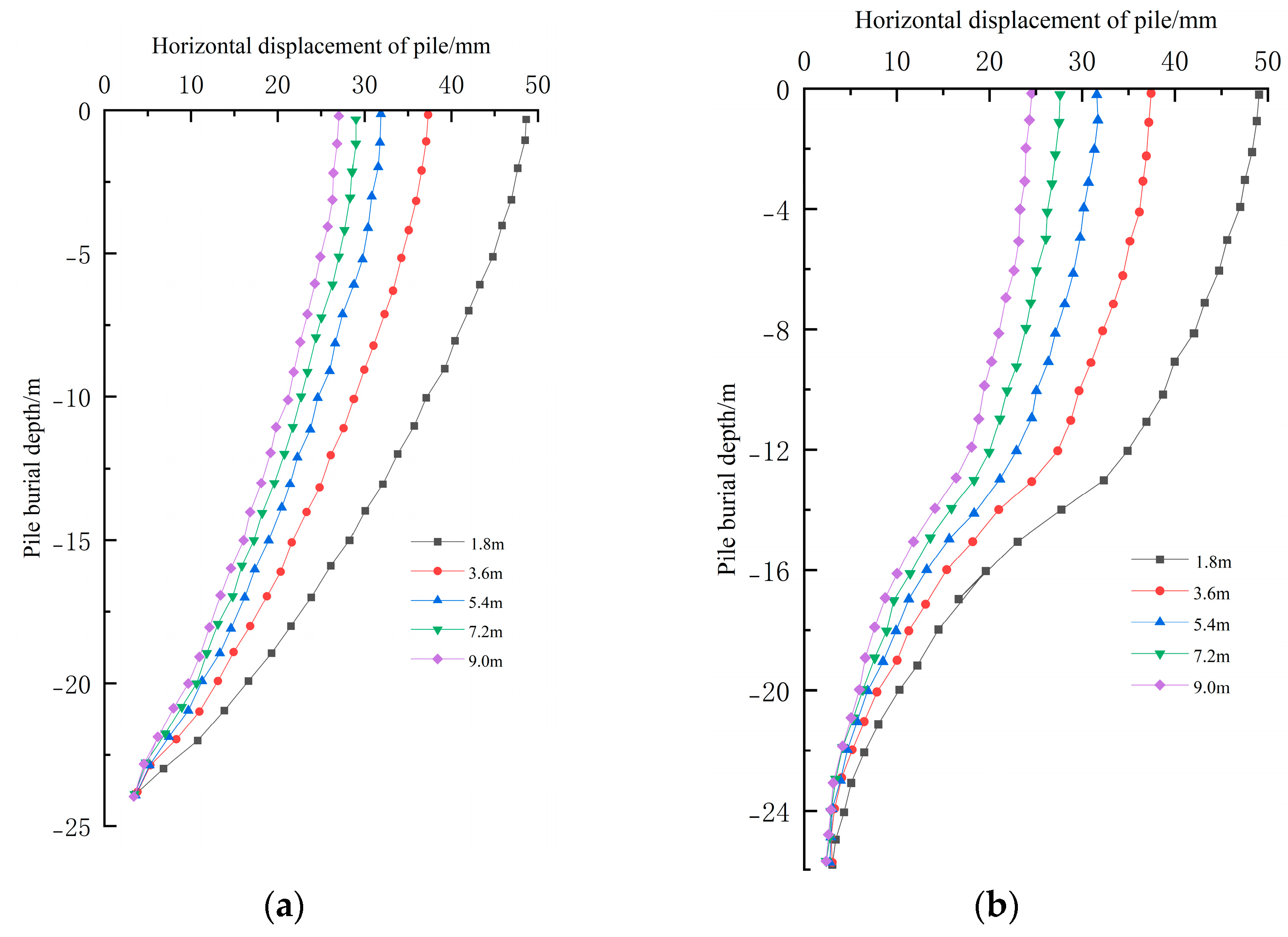
4.2.1. The Effect of Row Distance

The row distance is adjusted successively according to the principle of control variables, and the horizontal deformation data of the front- and back-row piles are shown in Figure 11. The change in the distance between the two rows of piles has a certain horizontal lateral movement on the top and bottom of the front- and back-row piles and shows the overturning deformation characteristics. Due to the restriction of the horizontal plate of the weighing platform, the maximum deformation of the pile body of the front- and back-row piles is basically the same. With the increase in the row distance, the horizontal lateral displacement of the front- and back-row piles decreases continuously. The horizontal displacement of the pile top in the current row is 48 mm, 37 mm, 33 mm, 29 mm and 27.5 mm, respectively, which increases by 29.7%, −11%, −21.6% and −25.7% compared with the 3.6 m row distance of the benchmark model. The horizontal displacement of the pile top in the back row is 48 mm, 36.4 mm, 32.8 mm, 29.4 mm and 27 mm, which increases by 31.9%, −10%, −19.2% and −25.8% compared with the 3.6 m row distance in the benchmark model. However, the horizontal displacement of the pile bottom in the front and back rows is less affected by the row distance. Therefore, the design process can meet the horizontal deformation on the basis of an appropriate widening row distance.

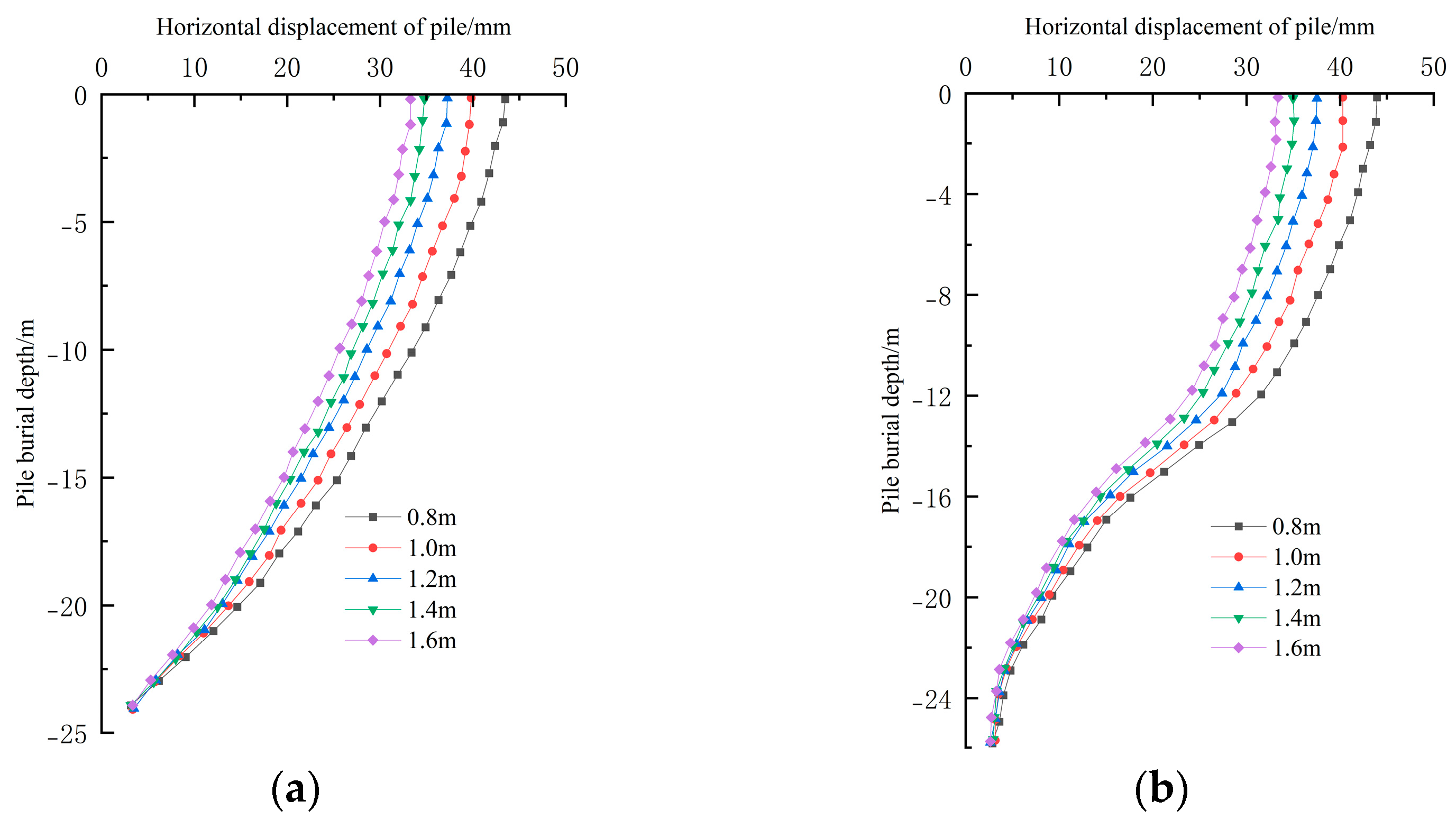
4.2.2. The Effect of Diameter of Back-Row Piles

The pile diameter of the back-row piles is adjusted successively according to the plan, and the calculated horizontal deformation data of the front- and back-row piles are summarized as shown in Figure 12. Due to the constraint effect of the weighing platform, the horizontal displacements of the front- and back-row piles with different pile diameters are basically the same, that is, with the increase in the pile diameters of the back-row piles, the horizontal displacements of the front- and back-row piles continue to decrease. Obviously, with the increase in the pile diameter of the back-row pile, the horizontal displacement of the front-row pile changes from a “convex curve” to a “straight line” distribution, while the horizontal displacement of the back-row pile remains unchanged, but the inflection point of the horizontal displacement of the back-row pile begins to move upward. The possible explanation for this phenomenon is that the increase in the pile diameter improves the overall stiffness of the supporting structure, resulting in most of the active soil pressure being borne by the back-row pile, which effectively limits its lateral displacement at the bottom of the foundation pit. More specifically, the horizontal displacement of the front pile tip is 43 mm, 40 mm, 37 mm, 35 mm and 33 mm, which increases by 16.2%, 8.1%, −5.4% and −10.8% compared with the pile diameter 1.2 m of the benchmark model. The horizontal displacement of the pile top in the back row is close to that in the front row.

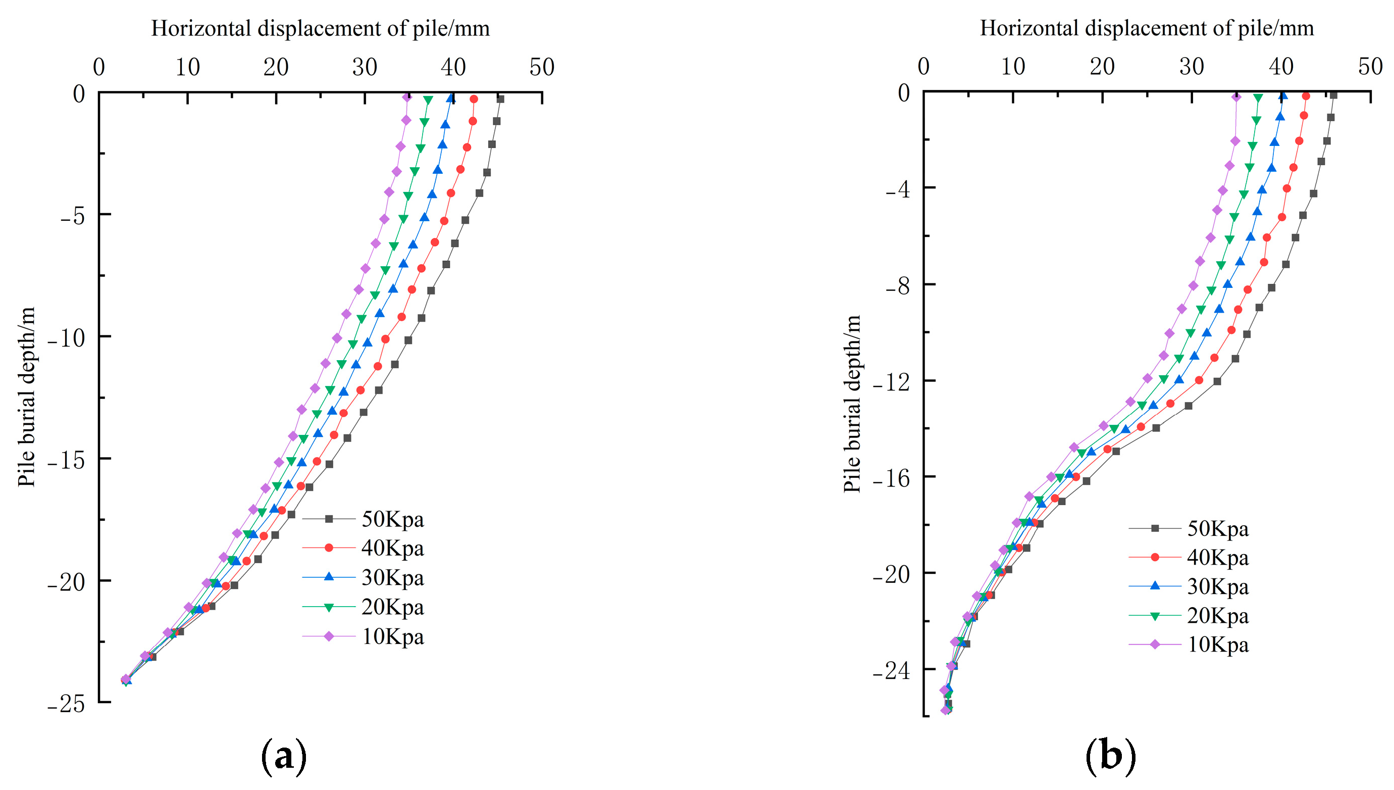
4.2.3. The Effect of Top Load

Figure 13 shows the horizontal deformation data of the front- and back-row piles under different pit roof loads. On the whole, the deformation of the front pile and the back-row piles are all overturning the deformation, and the change characteristics of the pile horizontal displacement are basically the same. With the increase in the pit-top load, the horizontal displacement value of the front pile and back-row piles keeps increasing. The top and bottom of the front- or back-row piles have some horizontal lateral displacement. The maximum value of the horizontal displacement occurs at the pile top, while the minimum value is at the pile bottom. When the horizontal displacement of the front pile top is 35 mm, 37 mm, 39.2 mm, 42.5 mm and 45 mm, respectively, the pile load of the pit top increases by −5.4%, 5.9%, 14.9% and 21.6% compared with the benchmark model of 20 kPa. The horizontal displacement of the top of the back-row piles is close to that of the front pile.
The above analysis of the three main structural design parameters of the row distance, diameter of the back-row piles and top load shows that the change in the front- and back-row distance has a greater influence on the deformation of the pile horizontal displacement, followed by the top load and diameter of the back-row piles. Moreover, because of the connection effect of the horizontal plate of the weighing platform, the whole supporting structure is hyperstatic. The horizontal displacement of the back-row piles is consistent with that of the front pile. It is reflected from the side that the back-row piles bear most of the lateral earth pressure, which is transferred to the front pile through the horizontal plate, thus improving the anti-deformation ability of the whole supporting structure.
Based on the above research, a horizontal load-bearing plate, as a new derivative form of a double-row pile, can connect the front and rear piles, which effectively im-proves the overall stiffness. The vertical retaining plate can better resist the earth pressure outside the pit and form the reverse pressure at the same time, which can effectively enhance the stability of the lower pile body. Its wide application in foundation pit engineering can effectively reduce the use of internal support and increase the construction surface, which is beneficial to the development of construction organization. Its use saves economic cost and improves economic benefit, which accords with the architectural concept of green ecological environment protection and sustainable development advocated at present.

5. Conclusions

Based on the results obtained from this study, we can draw the following conclusions:
(1) The calculation model of the active lateral earth pressure of the counterweight double-row pile applied in the software simulation is close to the field monitoring results, indicating the correctness of the calculation method and the feasibility of the application, which provides theoretical support for the simulation of the foundation pit supporting design of the counterweight double-row pile.
(2) The piles in the front and back of the counterweight double row of piles show the overturning deformation, and the horizontal displacement changes in the two rows of piles are basically the same. The maximum value of the horizontal displacement of the pile is at the top of the pile, and the minimum value is at the pile bottom. The horizontal displacement decreases with the increase in the distance of the back row, the diameter of the back-row piles. The change in the pile horizontal displacement caused by the pit-top load is contrary to it. It is concluded that the change in the front and back distance has a great influence on the horizontal displacement of the pile, followed by the load of the pit top and the pile diameter of the back-row piles.
(3) The whole supporting structure is in the form of a hyperstatic structure due to the connection effect of the horizontal plate of the weighing platform. The back-row piles can withstand most of the lateral earth pressure, which effectively reduces the deformation of the front pile, improves the overall stiffness of the supporting structure and is conducive to the stability of the excavation of a deep foundation pit in soft soil.
(4) Through the analysis of this paper, weighing a double-row pile can effectively reduce the use of internal support and increase the working face. Meanwhile, the construction organization design can not only reduce the economic cost but also accord with the concept of sustainable development of green and environmental protection.
The deformation mechanism under the convection-solid coupling effect is not explored in this paper, although the theory and parameter design of the counterweight double-row pile are considered. The stability of the counterweight double-row pile under a rainfall condition will be further discussed in the subsequent research.

Author Contributions

Conceptualization: Q.W.; software, C.Z.; writing—original draft preparation, writing—review and editing, B.D.; supervision, F.M.; project administration, L.Z. All authors have read and agreed to the published version of the manuscript.

Funding

This research was funded by the National Natural Science Foundation of China (grant no. 51474045).

Institutional Review Board Statement

Not applicable.

Data Availability Statement

Not applicable.

Conflicts of Interest

The authors declare no conflict of interest.

References

  1. Gu, W. Research on Weight-Bearing Double-Row Pile Support Structure; China Academy of Railway Science: Beijing, China, 2018. [Google Scholar]
  2. Cao, J.; Jiang, K.Y.; Gui, Y.; Liu, H.M. Research on Calculation Theory of Double-Row Piles Retaining Structure. Adv. Mater. Res. 2013, 671, 251–256. [Google Scholar] [CrossRef]
  3. Li, C.; Chen, W.; Song, Y.; Gong, W.; Zhao, Q. Optimal location of piles in stabilizing slopes based on a simplified double-row piles model. J. Civ. Eng. 2022, 24, 377–389. [Google Scholar] [CrossRef]
  4. Qi, Z.; Xu, Y.; Gu, W.; Pang, X.; Wen, J. Application of weighted double-row piles and large-span supports in oversized foundation pit support in reclaimed areas. Railw. Archit. 2020, 60, 104–108. [Google Scholar]
  5. Xue, D.; Li, T.; Zhang, S. Calculation method of slippage thrust behind double-row pile based on displacement control. J. Geotech. Eng. 2022, 1–8. [Google Scholar] [CrossRef]
  6. Liu, C.; Wang, Y.; Chen, J.; Zhang, X.; Zhang, R.; Chen, S.; Tan, Y. A simplified calculation model for a double-row pile support system for permanent slopes. Appl. Sci. Technol. 2022, 49, 106–112. [Google Scholar]
  7. Chhunla, C.; Suched, L. Underground excavation behaviour in Bangkok using three-dimensional finite element method. Comput. Geotech. 2018, 95, 68–81. [Google Scholar]
  8. Wang, Y.; Xia, X.; Wu, Y. Model Experimental Study on Support Structure of Double-row Piles in Deep Foundation Pit. Earth Environ. Sci. 2019, 267, 032062. [Google Scholar] [CrossRef] [Green Version]
  9. Ye, J.; Wang, C.; Huang, W.; Zhang, J.; Zhou, X. Effect of inclination angle on the response of double-row retaining piles: Experimental and numerical investigation. Teh. Vjesn. 2020, 27, 1150–1159. [Google Scholar]
  10. Xiong, S.; Li, C.; Yao, W.; Yan, S.; Wang, G.; Zhang, Y. Physical model tests and numerical modeling of stabilizing mechanism of portal double-row piles in landslides with interbedded weak and hard bedrock. Bull. Eng. Geol. Environ. 2022, 81, 1–18. [Google Scholar] [CrossRef]
  11. Yan, Y.; Xiao, S. Physical model test on the distribution of rear lateral thrust of double-row anti-slip piles. Chin. J. Geol. Hazards Prev. 2022, 33, 79–87. [Google Scholar]
  12. Zhu, Q.K. The Influences of Interpile Soil Reinforcement on the Performance of Structures with Double-Row Piles. Appl. Mech. Mater. 2012, 170, 195–198. [Google Scholar] [CrossRef]
  13. Likitlersuang, S.; Chheng, C.; Keawsawasvong, S. Structural modelling in finite element analysis of deep excavation. J. GeoEng. 2019, 14, 121–128. [Google Scholar]
  14. Nguyen, T.S.; Likitlersuang, S. Influence of the spatial variability of soil shear strength on deep excavation: A case study of a Bangkok underground MRT station. Int. J. Geomech. 2021, 21, 04020248. [Google Scholar] [CrossRef]
  15. Song, D.; Chen, Z.; Dong, L.; Tang, G.; Zhang, K.; Wang, H. Monitoring analysis of influence of extra-large complex deep foundation pit on adjacent environment: A case study of Zhengzhou City. China. Geomat. Nat. Hazards Risk 2020, 11, 2036–2057. [Google Scholar] [CrossRef]
  16. He, J.; Liu, H.; Liao, S.; Wang, D. Interaction between deep foundation pit and adjacent underground station under double-row pile support. J. Undergr. Space Eng. 2021, 17 (Suppl. S2), 821–831. [Google Scholar]
  17. Zhao, P.; Wang, Z.; Fang, C.; Yi, S. Analysis and control of deformation in excavation of deep foundation pits in soft soil under double-row pile support. Mod. Tunn. Technol. 2022, 59 (Suppl. S1), 1087–1094. [Google Scholar]
  18. Yan, B.; Hu, K.; Cao, M. Analysis of the influence of inter-pile reinforcement soil parameters on double-row pile support structure. J. Undergr. Space Eng. 2022, 18 (Suppl. S1), 226–232. [Google Scholar]
  19. Shen, Y.; Sun, H.; Shang, Y.; Wang, Y.; Yan, K. Optimal design of double-row anti-slip pile top connection. J. Rock Mech. Eng. 2010, 29 (Suppl. S1), 3034–3038. [Google Scholar]
  20. Gu, L. Finite element analysis and investigation of double-row piles supporting structure. Adv. Mater. Res. 2014, 838, 779–785. [Google Scholar] [CrossRef]
  21. Wang, Z.H.; Zhou, J. Three-dimensional numerical simulation and earth pressure analysis on double-row piles with consideration of spatial effects. J. Zhejiang Univ. Sci. 2011, 12, 758–770. [Google Scholar] [CrossRef]
  22. Zhou, J.; Wang, Z.H. Numerical Simulation Using Finite Element and Earth Pressure Analysis on Double-Row Pile Retaining Structures. Adv. Mater. Res. 2011, 261, 923–927. [Google Scholar] [CrossRef]
  23. Chandrasekaran, S.S.; Boominathan, A.; Dodagoudar, G.R. Group interaction effects on laterally loaded piles in clay. J. Geotech. Geoenviron. Eng. 2010, 136, 573–582. [Google Scholar] [CrossRef]
  24. Jiang, K.Y.; Cao, J.; Liu, H.M.; Zhao, H.M. Sensitivity Analysis on Influencing Factors of Double-Row Piles for Excavation. Adv. Mater. Res. 2013, 671, 290–295. [Google Scholar] [CrossRef]
  25. Wang, G.; Dong, C.; Fang, Z.; Chang, S.; Singh, J. Parameter Study on Double-row Pile in the Combined High Retaining Structure. Geotech. Geol. Eng. 2022, 40, 5233–5248. [Google Scholar] [CrossRef]
  26. Zhou, Y.; Yao, A.; Lei, G. Consideration of the Pile-Soil Friction for Earth Pressure of Limited Soil for Double-Row Piles. In Proceedings of the 2nd International Symposium on Asia Urban GeoEngineering; Springer: Singapore, 2018; pp. 174–183. [Google Scholar]
  27. Zhou, Y.; Liu, K.; Wang, F. Research on the Mechanical Properties of New Double-Row Pile Supporting Structure Based on an In Situ Study. Shock. Vib. 2021, 2021, 5177777. [Google Scholar] [CrossRef]
  28. Zhou, Y.; Chen, Y. Active and Passive Earth Pressure Calculation Method for Double-Row Piles considering the Nonlinear Pile Deformation. Geofluids 2022, 2022, 4061624. [Google Scholar] [CrossRef]
  29. Zhou, Y.; Luo, L.; Zheng, L. Review of the Deformation Mechanism and Earth Pressure Research on the Double-Row Pile Support Structure. Front. Earth Sci. 2022, 10, 933840. [Google Scholar] [CrossRef]
  30. Liu, S.; An, Z.; Li, X.; Li, Z. Analysis of influencing factors of double-row pile support structure. J. Jilin Univ. Constr. 2021, 38, 39–44. [Google Scholar]
  31. Hu, R.H.; Liu, G.N.; Pan, X.H. Determination of unloading plate parameters and pile length in weighted pile plate retaining walls. Railw. Archit. 2011, 453, 74–77. [Google Scholar]
Figure 1. Design diagram of double-row pile.
Sustainability 15 06184 g001
Figure 2. Calculation model for the design of counterweight double-row pile.
Sustainability 15 06184 g002
Figure 3. Three-dimensional finite element model.
Sustainability 15 06184 g003
Figure 4. Support structure model.
Sustainability 15 06184 g004
Figure 5. Rebar stress gauge.
Sustainability 15 06184 g005
Figure 6. Site monitoring.
Sustainability 15 06184 g006
Figure 7. Horizontal displacement of the front-row piles.
Sustainability 15 06184 g007
Figure 8. Horizontal displacement of the back-row piles.
Sustainability 15 06184 g008
Figure 9. Bending moment of front-row piles.
Sustainability 15 06184 g009
Figure 10. Bending moment of back-row piles.
Sustainability 15 06184 g010
Figure 11. Horizontal deformation of front- and back-row piles under various row distances. (a) Front-row pile, (b) back-row pile.
Sustainability 15 06184 g011
Figure 12. Horizontal deformation of front- and back-row piles under various diameters of back-row piles. (a) Front-row pile, (b) back-row pile.
Sustainability 15 06184 g012
Figure 13. Horizontal deformation of front- and back-row piles under various top loads. (a) Front-row pile, (b) back-row pile.
Sustainability 15 06184 g013
Table 1. Design parameters of each soil layer.
Stratigraphic (Genetic)Natural Weight (kN/m3)Elasticity Modulus (MPa)Cohesion
(kPa)
Internal Friction Angle (°)Permeability Coefficient (m/d)
1-1 Rockfill (Q4mL)20.01066323.0
2-1 Silt (Qm)16.5101060.005
3-1 Silty clay (Q4al+pl)18.54520160.05
4-1 Gravel clay (Qel)18.55421230.1
5-1 Completely weathered granite (γK1)19.015023280.2
5-2 Strongly weathered granite (γK1)20.024025320.5
Table 2. List of parameter adjustment schemes.
Variable Parameter
(Base Value)
Adjustment Range (m or kPa)
Row distance (3.6 m)1.8, 3.6, 5.4, 7.2, 9.0
Diameter of back-row piles (1.2 m)0.8, 1.0, 1.2, 1.4, 1.6
Top load (20 kPa)10, 20, 30, 40, 50
Disclaimer/Publisher’s Note: The statements, opinions and data contained in all publications are solely those of the individual author(s) and contributor(s) and not of MDPI and/or the editor(s). MDPI and/or the editor(s) disclaim responsibility for any injury to people or property resulting from any ideas, methods, instructions or products referred to in the content.

