Abstract
Dynamic response of flexible multi-body large wind turbines has been quickly growing in recent years. With the new normal economic policy, the economy of China is developing innovatively and stably. New energy development and utilization is an important strategy for people’s lives and economic development around the world. It is feasible to analyze from a broad perspective. In particular, the development and application of wind power is affecting the economic development of industry to a certain extent. Persistent and significant large wind turbines have cast concern over the prospects of wind power technology, and a comprehensive development potential of wind power technology has been analyzed its potential use in the future. The multi-body dynamics method can better analyze and describe the impact of flexible blade elastic deformation on motion characteristics and provides a practical analysis method for the aeroelastic stability analysis and control system design of wind turbines.
1. Introduction
The flexibility of the large-capacity floating underwork is incorporated into the dynamic calculation of the floating wind turbine through the use of the radiation diffraction solver directly. The process for constructing a dynamic flexible substructure model and the use of the WAMIT and HAWC2 aeroelastic tools are shown in [1]. The energy-consuming effect and the inertia-elastic effect of the flexible blade have a competing connection with the overall dynamic response of the wind turbine in the integrated blade-tower model of a large-sized wind turbine [2]. The coupled dynamic response of a multi-column low CG FOWT system located in shallow water area satisfies the extreme survival requirements of the FOWT system in the shallow water (50 m) in the South China Sea, in addition to the standard operating requirements and the new concept of the system that is available in [3]. The double frequency effects on the dynamic responses of the flexible tower structure in [4] could be induced by regular waves. We use the multi-body dynamic analysis approach for fatigue design of the monopile foundation of an offshore wind turbine. Aero-hydro-servo-elastic analysis was used to model the dynamic response of the combined system. Each soil layer that was simulated by p-y curve is available in [5]. A new prediction model for calculating unsteady loads, modal characteristics, and structural dynamic responses of blades and towers under various wind conditions is accurate and reliable with high calculation accuracy. The time-variant dynamic responses of blade tip and tower top under NTM and ECD are available in [6]. When the orientation of the elastic bending-torsion coupling in the blade is twist-to-feather, it has a favorable influence on the dynamic response of the turbine. The impact is finally reflected in decreased aerodynamic stresses on the blade, as can be seen in [7]. A multi-bodies hydrodynamics and lumped-mass approach-based time-domain hydroelastic model has been proposed. Investigated are the structural loads, VLFS flexible deformation, and wind turbine power output. The results are available in [8]. The combined concept of CTC demonstrates that, in comparison to CSCs, it performs fairly well in increasing the yearly generation of power. The structure of CTC is shown in [9]. The flexibility caused by the pile–soil interaction reduces the natural frequency of the tower, thus affecting the response of the tower, and the tower shows a stronger response at its natural frequency [10]. The fender system in the new installation method for floating offshore wind turbines, which is available in [11], showed a reduction effect on relative horizontal and vertical displacements, relative alignment, and relative stability by approximately 78%, 64%, and 32%, respectively. The elasticity of the blade and tower has little effect on the dynamic response of floater, and the dynamic equation of floating VAWTs based on multi-body kinematics and dynamics theory considering rigid-flexible aerodynamic coupling is available in [12]. For large blade strains, the FSI model can more accurately represent turbine performance than CFD, thus compromising aerodynamic performance and structural robustness [13]. The MBBT-MCM coupled method is used to study the overall dynamic response of FOWT, especially for highly compliant designs [14]. In the dynamic response analysis of a power transmission system, the bedplate must be viewed as a flexible body with high modes [15]. The resonance responses of a new experimental FWT model are induced under strongly nonlinear hydrodynamic loads [16]. In the new HAWT comprehensive nonlinear dynamics model, centrifugal force, angular velocity dependent terms, rotational inertia, and pre-twist have great influence on the dynamic response of blades. For more dynamic response data, see [17]. Compared with the traditional algorithm, the load shedding strategy of a large flexible wind turbine rotor with controllable flaps driven by the new modeless adaptive control algorithm can effectively reduce RBM and BTD, thus prolonging the fatigue life of the wind turbine [18].
The research on the dynamic characteristics of a rigid-flexible coupling system of large-scale wind turbines mainly examines nonlinear vibration and aerodynamic response characteristics under multi-load coupling. That is, considering the multi-load coupling effect, the dynamics of a rigid-flexible coupling system of large wind turbines is studied by nonlinear analysis. Through multi-load coupling and pulsating wind excitation, the influence of dynamic parameters such as vibration displacement, linear velocity, and phase difference on the stability of wind turbines is analyzed and the wind turbine is studied [19]. The key component of nonlinear vibration is important. Through the hydrodynamic analysis of the flange at the section of the tower, the distribution law of the fluid around the tower is revealed with the change of the flange structure. The relationship between the bolt working load and the stress of the flange under different working conditions is deduced, and the main factors affecting the stability of the tower are obtained. The research on dynamic characteristics of a rigid-flexible coupling system of large wind turbines is an applied basic research subject, which will provide certain reference value for condition monitoring and fault diagnosis of large wind turbines. The innovation of the present paper is based on a comprehensive study of the dynamic structure of flexible systems with multiple components, which will improve the stability and stability of the wind turbine and support the growth of industrial chains.
The efficiency of a wind turbine would be reduced in sandstorm weather [20]. The combination of different types of wave energy converters can be more effective in suppressing the motion response while increasing the total wave energy generation [21]. The standard deviations of heave and pitch motions of the helical type of floating wind turbine are slightly smaller than those of floating HAWT, while the standard deviations of surge and yaw motions are larger [22]. A hydraulic transmission applied to a utility-scale spar floating wind turbine eliminates the need for a gearbox and potentially improves the turbine reliability [23,24,25]. The GMPOP-based method, which is an effective way to assess the dynamical alteration of wind turbine, can successfully detect the state anomalies before the occurrence of the outer race fault and inner race fault, and provide anomaly alarms in advance [26]. The optimized articulated offshore wind turbine is significantly improved in terms of construction cost, structural stability, motion performance, and power generation stability, and fully satisfies the operating requirements under different sea scenarios [27]. The thrust and torque caused by the rain-induced load increase as the rain intensity increases [28,29,30]. The wave energy converters can obviously contribute to the annual power production of the combined concept when compared with an individual floating wind turbine [9]. Airfoils’ kinematics significantly affect the load predictions during the dynamic stall phenomenon [31]. The computational time required for models which are simplified is less than 10% that of the full-order model, without the compromise of accuracy, i.e., less than 5% difference in modal frequency and an excellent agreement in time-domain responses [32]. The electromechanical–rigid-flexible coupling dynamic model improves the stability and safety of the system, particularly under gust conditions [33]. Through analyzing the dynamics of FWT platform mooring from structure creep to failure, it was found that the yaw response is the most sensitive to structural damage [34]. The shared anchoring system applied to offshore floating wind turbines further reduces the cost of wind turbines by reducing the cost of manufacturing and installation [35]. Platform yaw motion is an important dynamic mode of the systems, particularly for the spar configuration [36]. DMD has been applied to the wake of the NREL-5MW wind turbine invested by a uniform inflow, to identify the most dynamically relevant coherent structures characterizing this flow [37]. By taking the non-Gaussian characteristics of wind fields into account, the short-term extreme values are generally larger than those under Gaussian wind fields [38].
This review work is organized in the following fashion. In Section 1, the structure of flexible multi-body wind turbine and potential of wind energy development are described, and the objectives of this paper are identified. In Section 2, the typical structure of wind turbines is introduced. The mechanical structure dynamic response of a flexible multi-body in large wind turbines are then discussed in Section 3. Transient response of the flexible blade in large wind turbines can be found in Section 4. In Section 5, the aeroelastic coupling of a flexible turbine blade is proposed to improve the understanding of the flow behavior of the turbine blade. The final conclusion is presented in Section 6.
2. The Typical Structure of a Flexible Multi-Body Wind Turbine
The platform floats in dense seawater and is connected to the sea surface by a three-line system of catenaries. The dimensions of the platform, tower, nacelles, and rotator, as well as the mass and inertia, are available in [39,40]. A schematic diagram of the flexible multi-body large wind turbines to be analyzed is shown in Figure 1. The coupled dynamic model of rigid and flexible multi-body is composed of three rigid bodies and one flexible body, as shown in Figure 1.
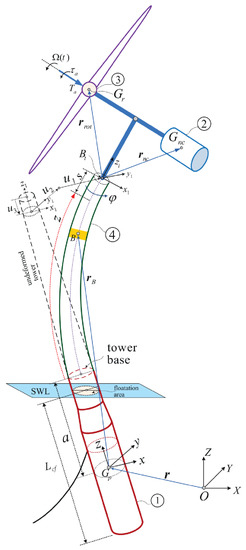
Figure 1.
Schematic diagram of the spar floating OWT multi-body dynamic model showing the system components and kinematics [19]. ①: the floating platform, with mass mp, and inertia tensor Ip = diag(Ipx, Ipy, Ipz). This platform has been proposed to support theNREL 5 MW baseline wind turbine. ②: the nacelle, a rigid body, with mass mnc, and inertia tensor Inc = diag(Inex, Incy, Lncz). ③: the rotor, a rigid disc spinning around its axis withangular velocity Ω(t). The mass is mr,and inertia tensor Ir = diag(Irx, Iry, Irz). ④: the tower, a flexible tapered 3D beam of annular circularsection. The beam is of length l, density ρt, and variable crosssectional area per length At(z).The moments of inertia of the cross section as functions of the tower height around the x1 and y1 axes are It,xx(z) and It,yy(z), respectively. The corresponding polar moment of inertial is Jt(z). The material properties of the beam are characterized by Young’s modulus E and modulus of rigidity G.
The researchers began their analysis by conducting a wind power generation technology potential assessment, Chinese wind power generation technology and industrial capacity had significantly improved, the Technology Research and Innovation Centre had gradually risen, in the promotion of market demand and competition, and Chinese wind power equipment manufacturing technology had accelerated the process of internationalization [41]. With the rapid expansion of wind power development and utilization, the trend of Chinese wind power development in accordance with the development of large-scale, centralized construction and long-distance transmission had steadily progressed [42]. The wind power grid and consumptive problem is gradually improving, due to the fact that wind power and power grid construction are not synchronized, the local load level is low, and China wind power and consumption is the result of the development of the main factors [43]. As the state has placed importance on China’s development of the power grid, wind power grid and consumptive problems are gradually improving.
3. The Mechanical Structure Dynamic Response of a Flexible Multi-Body in Large Wind Turbines
The dynamic characteristics of the rigid-flexible coupling system of large wind turbines are studied. The wind turbine is regarded as a rigid-flexible coupling system and the tower and blade are regarded as the main elastic bodies of the wind turbine which form a rigid-flexible coupling system with the engine room. Nonlinear vibration directly affects the coupling between wind turbine components. The vibration of the rigid-flexible coupling system of large wind turbines is a nonlinear coupling vibration. Displacement and stress changes will affect the stability of wind turbines. With the increase of tower height, the dynamic characteristics of flexible components and rigid-flexible coupling structures of wind turbines are more and more important to the stability of the system. The aerodynamic response of the rigid-flexible coupling system has an impact on the stability of large fans. The induction factor directly determines the induction speed, so as to obtain the change of wake flow and provide a reference for the safety and stability of large fans.
In this paper, the three-dimensional finite element method is used to simulate the unsteady CFD of large wind turbine units, and its numerical calculation is carried out. The unsteadiness of the changes in speed, mode of motion, and stress in the circle is explained and analyzed [44].
Wind power generation technology is mature and low cost and has played a great role in reducing carbon dioxide emissions. Therefore, it has great room for development in the clean energy market. The aerodynamic characteristics of wind energy play an important role in the field of wind energy, which can be seen in Figure 2 [45]. Figure 2 shows the installed generation capacity of the power sector between 2006 and 2015 with conservative projections to 2040 according to the U. S. EIA, IRENA, and GWEC statistics. Wind and renewable capacities are represented by the primary axis, while the total is represented by the secondary axis. Wind energy contributes greatly to the increasing penetration of renewables into the electricity generation sector and constitutes around 30% of the renewable capacity. Therefore, wind power deserves a deeper survey.
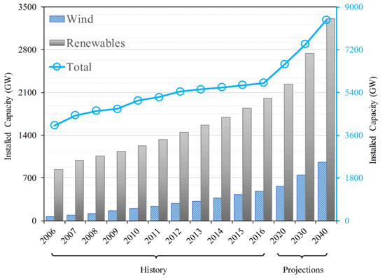
Figure 2.
The global energy demands with specific shares of wind and renewable energies between 2006 and 2016 with projection to 2040 [26].
Figure 3 shows the geometry of the wind turbines of Krogstad and Lund. Through the simulation of a dry orchid seed, the geometric shape of the bionic wind turbine blade is obtained. The wing picture of winged seeds is taken from another angle. We used GetDataGD to draw and extract the section formed by the edge and middle of the wing segment from the above picture. Together, these contours form the leading edge, corner, and tail edge of the bionic wind turbine to be built. It is assumed that the shape of blade profile is a curve formed by the profile and radian of each blade. Because the thickness of the wing section is the same only at the root, a fixed wing thickness in this study is proposed to facilitate the establishment of the 3D model. The geometry of the blade was then scaled once into the meant rotor measurement of 0.9 m in diameter [46].
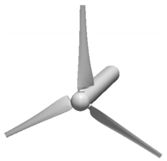
Figure 3.
A 3D model of the tapered and twisted blades wind turbine from Krogstad and Lund [46].
Figure 4 provides a visual impression of the simulated rotor configuration. The grey geometry in Figure 4c,d represents the reference configuration C1. Shaft inclination and blade taper are specified in accordance with Reference Report 5 and 2.5, respectively. Since there is no official description of the shape of the nacelle and hub, the general shape is used [47].
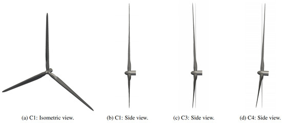
Figure 4.
Overview of the simulated rotor configurations [47]. (a–d) Visual impression of simulated rotor configuration.
Figure 5 shows the influence of the slenderness ratio on the dynamic performance of the OWT structure with rigid and flexible single piles. It should be noted here that in this paper, the change of the slenderness ratio is only a function of nh, so the bending stiffness of single pile is basically unchanged. It can be seen from the figure that the stiffness correction coefficient of rigid single pile and flexible single pile γ K increases with the increase of the slenderness ratio. The lower limit of this parameter is close to zero, indicating that the structure will develop towards instability [48].
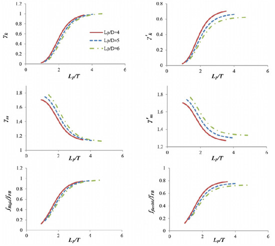
Figure 5.
Effect of pile slenderness ratio LP/T on the stiffness correction factor γk, mass correction [48].
All rotor blades were manufactured with the use of a poured polyurethane molding process, with rigid and flexible blades being identical at some stage in manufacture, as shown in Figure 6. In this type of test, for simplification, all blades are designed as symmetrical sections, and the airfoil is consistent with the section of NACA 0015. In order to test blades at different pitch angles, the hub was manufactured using a harder version of ABS plastic. The cylindrical hub is 0.05 m in diameter, extends to a span of 0.0604 m, and then, at a span of 0.0804 m, transforms to the appropriate NACA 0015 shape. The chord length at this span is 0.096 m. At a span of 0.5604 m, the blade chord linearly declines to a chord length of 0.048, and at a span of 0.5714 m, it tapers off to a cylinder tip with a diameter of 6 mm. Blades that are stiff were created utilizing a rigid substance that does not flex when in use [49].
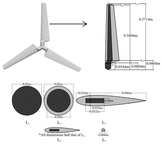
Figure 6.
Flexible rotor description showing rigid parts (shaded dark) [49]. * The size of the blade tip section in all directions is half of the blade root.
The relative rotation between the rotor and the blade frame could be used to define the twist angle of the blade. Most researchers use approximate aerodynamic models based on XFOIL software results. For a given angle of attack, Reynolds number, and Mach number, XFOIL provides the pressure distribution, CP(x), lift coefficient, CL, drag coefficient, Cd, and the lift-to-drag ratio, as shown in Figure 7 [50].
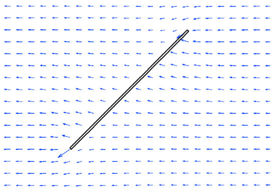
Figure 7.
Velocity distribution around flat plate [50].
The connection between the rotor and the main shaft serves as the primary excitation source in terms of dependability. The effects of radial, thrust, and bending loading DOFs are studied. The forces at the rotor-main shaft connection serve as the input for each of these FRFs. Figure 8 shows the rotor-main shaft coupling and the corresponding forces. The maximum reaction of DOFs is the displacement of the luggage rack and transmission bushing at the rear PLC-B position [51].
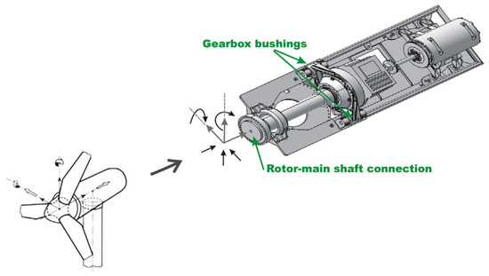
Figure 8.
Interface points for the FRF calculations [51].
The rotor is positioned in the middle of the cylinder-shaped computational zone, which has a length of 20 D and a diameter of 10 D and is seen in Figure 9a. The flow area is divided into rotational area and stationary area, and the information exchange between the two areas is realized through the sliding mesh technique. The entire flow field was meshed with hexahedral cells. Figure 9b,c shows the rotating area and the grid around the blade, which are generated by the O4H topology. In order to test the independence of the model, this paper proposes two different types of blade models, in which the mesh number of each blade is about 0.7 M and 2.8 M, respectively, and simulates them. The coarse grid and fine grid around the blade are shown in Figure 9c,d, respectively [52]. The maximum difference between the results obtained using refined grid and coarse grid is 19.22% and it occurred at wind speed of 5 m/s. This result from the ratio of lift to drag of airfoil is highly sensitive to grid distribution at a low angle of attack. The second maximum percentage difference (less than 3%) occurred at the free stream wind speed of 15 m/s, which is due to the complex flow phenomena, such as separation occurring at blade root, which are also highly sensitive to grid distribution. In the case of intermediate wind speeds, the difference between two sets of grids can be neglected.
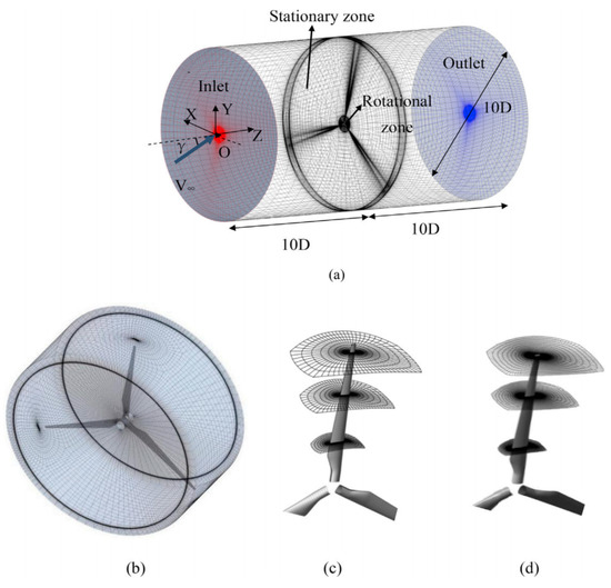
Figure 9.
(a) Computational zone and global mesh; (b) rotational zone mesh; (c) coarse mesh around blade; and (d) refined mesh around blade [52].
In addition to showing cross sections in the Mann’s box with non-dimensional axial velocity U, Figure 10 provides a generic schematic for the incorporation of the Mann wind turbulence model into CFD Ship-Iowa v4.5 as a wind turbulence boundary condition. A stationary Mann wind turbulence box is created as a preprocessing step [53]. Given that the velocity field is constructed in a periodic manner, the box’s dimensions are set to span a number of integral length scales, allowing the velocity fields on either side of the box to be treated as uncorrelated. The front face of the Mann box and the CFD domain’s inlet meet at time t = 0, as seen in Figure 10.
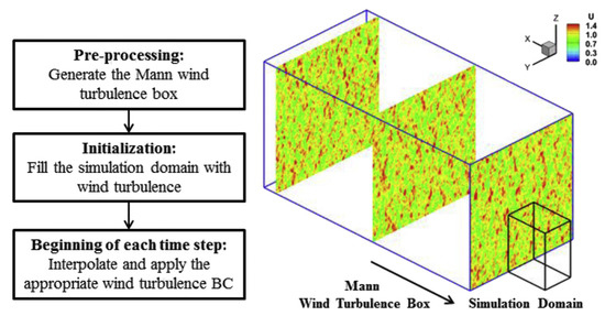
Figure 10.
Schematic of implementation for Mann wind turbulence model [53].
With the shortage of traditional energy and the increasing use of renewable energy, wind energy is one of the fastest growing and most widely used renewable energy sources. Wind power is the main form of wind energy utilization. Large-scale wind turbines are the trend of wind power generation of the future. The tower, wind turbine, and engine room, which are the key components of wind turbines are composed. A rigid-flexible coupling structure and the dynamic characteristics of its rigid-flexible coupling system are the key problems in the operation of wind turbines, which provides a reference value for condition monitoring and control of a large wind turbine. It has broad application prospects in operation, optimization, and control.
Importantly, the development and industrial concentration of large wind turbines may be an important trend of wind power technology. In 2017, China’s wind power equipment was mainly manufactured by more than 10 large wind turbine manufacturers. Mergers and acquisitions of wind power equipment manufacturing enterprises can increase gradually. China’s wind power manufacturing companies have completed the industrial layout. In the main markets, they have established factory production bases. A large company is equivalent to integrating multiple companies. The horizontal axis wind turbine technology is still mainstream. Because of its high conversion efficiency, shorter wind axis, and more economic advantages in large wind turbines, the horizontal axis wind turbine is still the mainstream model for the development of large wind turbines and accounts for more than 100% of the market share. Variable pitch power regulation technology has been widely used in wind power development. It combines the application of variable pitch technology and power electronics technology. Most wind turbine manufacturers have adopted variable speed constant frequency technology and developed variable pitch, variable speed wind turbines, which further improve the conversion efficiency of wind energy. The rapid development of direct-driven wind power technology can effectively reduce the faults caused by the gearbox, and thus effectively improve the service life and reliability of the system operation and reduce the maintenance costs of a wind farm, which have gradually won the favor of the market. Various full-power converters for wind turbines have been applied. With the increase of high-speed gearboxes for direct-driven permanent magnet wind turbines and high-speed permanent magnet wind turbines, full-power converter technology has been widely developed and applied.
The potential development prospects of wind power generation technology in China are as follows. China is rich in wind energy resources. The reserves of developed and utilized wind energy are about 1 billion kilowatts, the reserves of onshore wind energy are about 253 million kilowatts (the height for 10 m), and the reserves of developed and utilized marine wind energy are about 750 million kilowatts, with a total of 1 billion kilowatts. Large-scale offshore wind power is still the direction of technological development in recent years. In the future, the cost of wind power will show a downward trend, which is mainly affected by wind energy resource conditions, wind farm construction conditions, wind power generation technology and cost, wind farm operation and management technology, and other factors.
4. Transient Response of the Flexible Blade in Large Wind Turbines
This method uses the vortex ring singularity grid with constant cycle GietT to solve the potential flow on the lifting surface, as shown in Figure 11. This method is based on the time stepping technique. At the initial stage, there was only one blade constrained vortex. At each stage, the blades move in the fluid, and a row of vortex ring elements fall off from the trailing edge and convection, forming a free vortex plate (i.e., wake). The intensity of this eddy current is known and equal to the cycle obtained in the previous time step (at the trailing edge). This is equivalent to the Kutta condition of unsteady flow. When the vortex is separated, its strength remains unchanged (Kelvin’s law) and does not carry aerodynamic load, so it moves with local speed [34].
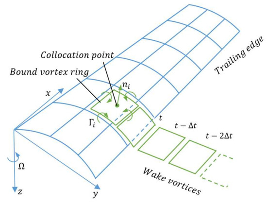
Figure 11.
Schematic of the vortex ring model for the unsteady flow [54].
The wind velocities in the rotor plane are depicted in Figure 12. The resultant wind velocity on the profile is denoted by Ve (x3, t). V1, 0 and V2, 0 denote the mean axial wind and rotational velocity components co-directional to the moving x1- and x2-axes, respectively, and ɑ and ɑ’ are the related axial and tangential induction factors, respectively [55]. V1(x3, t) and V2(x3, t) are the instantaneous wind velocities in local x1-direction and x2-direction, respectively, seen by an observer fixed to the moving (x1; x2; x3)-coordinate system.
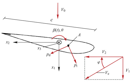
Figure 12.
Wind velocities in rotor plane [55].
This method regards the whole system as two rigid bodies: the tower body is an integral structural component, which can carry the whole RNA, including a floating ship body; RNA is a complete component that can be offset from the tower on the machine. The implementation of this method requires the use of multiple coordinate systems to derive the EOM of the entire system. In the dynamic equation, the external excitation is continuously calculated and projected into the corresponding coordinate system. Figure 13 shows the (X, Y, Z) and (XM, YM, ZM) systems, which are the fixed global coordinate systems of the earth. The origins are located at the CM and static water level of the whole system. If the system is in zero displacement equilibrium state, see [56].
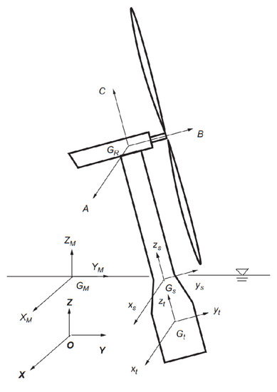
Figure 13.
Coordinate systems used in the application [56]. A is horizontal direction, B is Perpendicular to the direction of the rotation plane, C is Vertical direction.
According to Figure 14, the rotor-nacelle system is made up of elastic blades, a rigid hub, a rigid engine room, a generator, etc. A permanent joint connects the bottom of the engine room to the ground. In this way, the rigid cabin will remain stationary during the simulation process. The generator is simplified to a rotary joint of 17.2 rpm. The three-bladed rotary joint, which runs parallel to the engine room’s center line, joins the compartments together. The shaft can be rotated by the blades. Each blade’s root does not flex during rotation, yet the elastic blade may move about freely. The combined effects of inertial force, elastic force, and aerodynamic force operate on the blade as it rotates, and gravity, Coriolis force, and centrifugal force are the three basic types of inertial force. As illustrated in Figure 15, the multi-point approach is used to apply the aerodynamic force to the blade structure of each blade section after the aerodynamic force has been computed using the free vortex wake method. The multi-body approach developed in this study is used to determine the structure’s dynamic response [57].
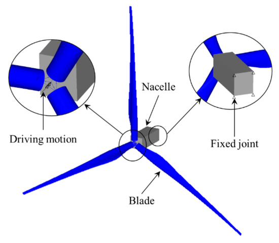
Figure 14.
Rotor-nacelle system [37].
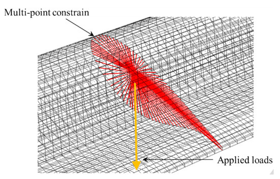
Figure 15.
Location of applied forces [57].
The guide-roller system at their interfaces is used to link the two rigid bodies that make up the MWWC system (a monopole type FWT and a heave type WEC), as illustrated in Figure 16. The AQWA code, which is adaptable for modeling multi-body systems and can accommodate the introduction of both mechanical and hydrodynamic couplings between two bodies, was used to simulate the hydrodynamic properties and the coupling interaction effects of two rigid bodies involved in the MWWC system. In Figure 17 [58], hydrodynamic panel models are displayed.
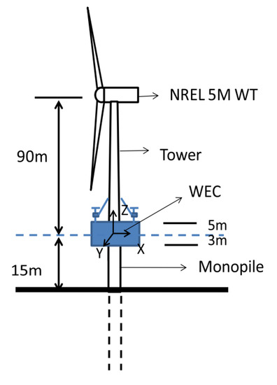
Figure 16.
Sketch map of the MWWC concept system [58].
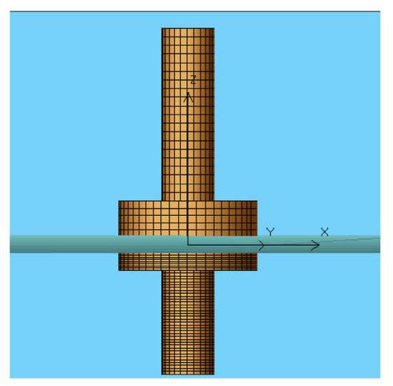
Figure 17.
Panel models for hydrodynamic analysis [58].
With regard to the role of swell, there is no ocean condition in multiple directions, which may lead to the difference between the average direction and the peak direction. Therefore, the average wave direction is a good estimate of the wave direction, and the uncertainty is within 30° (93% confidence interval). In order to construct the wind rise and wave rise as shown in Figure 18, the directions are divided into 12 directions, 30° each, and the distance between the main wind direction and the wave is 10° [59].
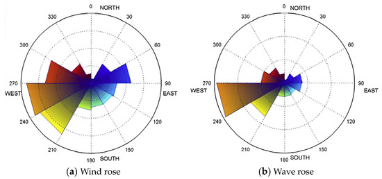
Figure 18.
Wind and wave roses with 12 bins of 30° [59]. (a) Wind rose in 12 average wave directions. (b) Wase rose in 12 average wave directions.
It can be seen from Figure 19 that the studied section is separated by a 1 m thick segmented uniform layer. When the depth exceeds 80 m, it is assumed that the shear rate is constant with the depth (half space domain). Soil density ρs = 1800 kg/m3, Poisson’s ratio νs = 0:35, and the hysteretic damping factor ξs = 5% remains unchanged. The suggested approach consists of a three-step process that creates a simplified model to analyze the variations in fundamental frequency and damping brought on by the rigidity of the foundation [60]. The soil profiles assumed for the sites in the analyses are presented in terms of the shear wave velocity cs in Figure 19. The value of the cs, 30 (Eurocode, 2004), for each profile is also displayed above each plot as it is widely used to characterize the soil. The selected profiles correspond to C (180 < cs, 30 < 360 m/s) or D soils (cs, 30 < 180 m/s), which are the ones that OWT systems are usually founded on.
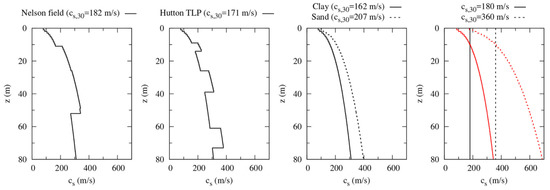
Figure 19.
Soil profiles used in the study. Evolution of the shear wave velocity with depth [40].
The temporal history of the rotor speed and pitch angle during the initial seismic loading excitation is shown in Figure 20. The test findings demonstrate that during typical operation, the rotor speed and pitch angle fluctuate continually. According to the characteristics of boundary element method and airfoil, it is ascertained that under normal working conditions, the average value of trust on the tower top will be larger than that in the parking state due to the shift in rotor speed and pitch angle. This is why the average value of structural response in the first case is greater than that in the second case. Modeling findings suggest that, when subjected to both earthquake and aerodynamic forces, the dynamic response of large wind turbines is reduced compared to when they are in a stationary state under normal conditions [61].
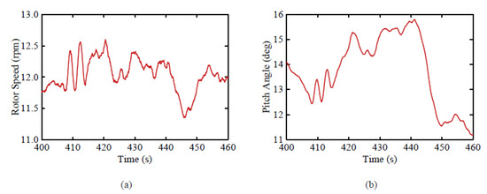
Figure 20.
The time histories in operation condition for: (a) rotor speed and (b) pitch angle [41].
5. Aeroelastic Coupling Analysis of the Flexible Blade of Large Wind Turbines
In NREL 5 MW HAWT blades, four super-elements are used to construct the blade topology, as shown in Figure 21. Because the last rigid body of the supercell is rigidly connected with the first rigid body of the next adjacent supercell, they can be combined into a rigid body (the merged bodies are shown in Figure 21 as B4, B7, and B10). In this way, the blade is divided into 13 rigid bodies with a total of 21 DOFs [62].
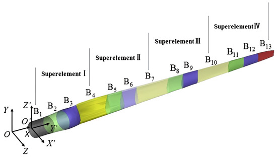
Figure 21.
Regular mark numbers of each rigid body, the inertial coordinate system XYZ and the blade coordinate system X’Y’Z’ [62].
The speed of LSS is consistent with the reference. This is because the coupling equation estimates the required torque, so that the support in the gearbox can achieve the reference speed, so that sufficient load transfer can be carried out on the gearbox connected to the generator. It must be underlined that the carrier speed depicted in Figure 22b corresponds to the solution of the state given to the carrier once the EOMs are resolved at each instant (that is, the dynamic response of the carrier). The mechanical controller used in this test is carried out according to the reference value and compensates forthe step change of power accordingly. In the transient process, damping plays a key role in the whole system. Although the steady-state values of the rotor speed are compared, there are differences in the changing rules of the rotor speed under the stable state. This is because the control parameters of the simulation and the actual system are different. In addition, the torque reached its peak at about 110 s. In this case, the vibration is due to the change of speed step, as shown in Figure 22b. However, from the consistency of test results and simulation results, the damping in the model is reasonable [63].
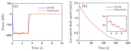
Figure 22.
Validation of the dynamic response of the drive−train model. The figure shows the generator electric power and speed in the low-speed shaft [63]. (a) The power of DUDE and experiment. (b) The low-speed shaft speed of DUDE and experiment.
As an illustration, Figure 23 depicts the dynamic reaction of an NREL-5MW RWT’s rotor under changing circumstances brought on by tower interference. The NREL-5MW RWT served as the foundation for constructing scenarios of quick pitch-control actuation for the current study. It is a well-known benchmark for a cutting-edge turbine. Measurable qualities in the presence of the tower revealed fluctuations that impact the loads operating on the rotor and its performance, such as variations in thrust and torque as well as power deficits. When the NREL-5MW RWT is operating at its nominal operational settings of 12:1 rpm, the instantaneous power P is shown in Figure 23a for a period of 5 s, which is comparable to the period of rotation. The three pulsations in the instantaneous power generated each time a blade crosses in front of the tower are seen in the 5 s span. Along with a reduction in average power relative to a rotor running without tower interference, pulsation also has an adverse impact on instantaneous power, as shown by the horizontal lines in Figure 23 [64]. As an example of the fluctuating aerodynamic conditions on the blade sections, Figure 23b shows the angle of attack on the section located at 90% span from the root of the blade.
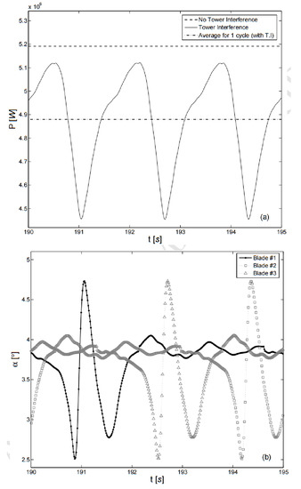
Figure 23.
Rotor behavior due to tower interference—(a) power generated P, and (b) angle of attack a, against time span on operation that includes one cycle of rotation [64].
The reference wind turbine’s single pile foundation (bending moment, Mx), tower top (displacement, dy), and dynamic (time-history) response are shown in Figure 24 under the effect of various hazardous environments in three operating scenarios. It should be pointed out that after 300 s, seismic excitation, namely the seismic activity of Northridge and Tabas, requires more energy after 300 s. The same conclusion is also obtained by seismic excitation of OWTs supported by tripod and jacket. Especially in the 5 MW power system, due to the impact of the earthquake, the demand coefficients of Mx and dy increased by 496% on average, while the demand coefficients of dy increased by 425% on average. Such seismic damage management emphasizes the need to incorporate seismic forces into the structural design and evaluation of wind turbines [65,66].
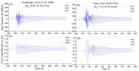
Figure 24.
Response time−histories of the 5MW OWT [65,66]. (a) Dynamic response of base moment under three operating scenarios under excitation of the Northridge earthquake motion. (b) Dynamic response of base moment under three operating scenarios under excitation of the Tabas earthquake motion. (c) Dynamic response of tower tops under three operating scenarios under excitation of the Northridge earthquake. (d) Dynamic response of tower tops under three operating scenarios under excitation of the Tabas earthquake.
Figure 25 shows that in order to help the reader understand the basic assumptions discussed in the next part, the model will be introduced briefly, and then we will use the nonlinear model to test the linear perturbation dynamics. The platform, engine room, and rotor are rigid bodies, and the only elastic body is the tower. This model does not contain a single rotor blade but simulates the rotor as a rigid disk. This model has been greatly simplified and provides a clearer view of the main system dynamics [67].
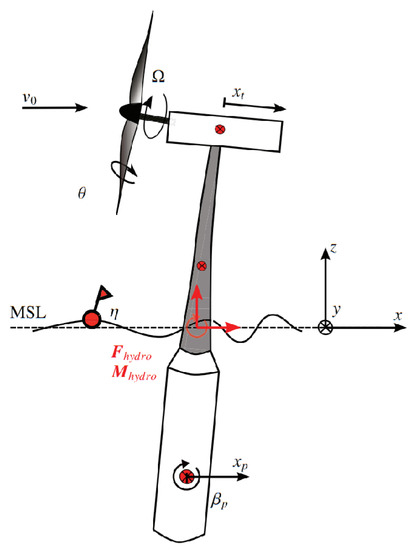
Figure 25.
Topology of the simplified multi-body model [67].
As mentioned in the introduction, the OWT supported on the jacket is a fixed base structure, while the role of SSI is ignored. Under this assumption, the legs of the substructure are connected with the mud line. In this part, the overall maximum average response of the OWT structure under the rated wind speed has been studied. This is compared with the response obtained by including soil components, as shown in Figure 26. Different from the model based on the fixed model, the introduction of soil will make the system more flexible to some extent, which will improve the response, and its size depends on the soil stiffness [68]. As observed from Figure 26, the stiffer, dense sand has a lateral response marginally greater than that of the fixed OWT. However, offshore wind farms may not always be sited on such uniform, ideal soil profiles and this necessitates the analysis of OWTs using realistic soil data, which may be layered.
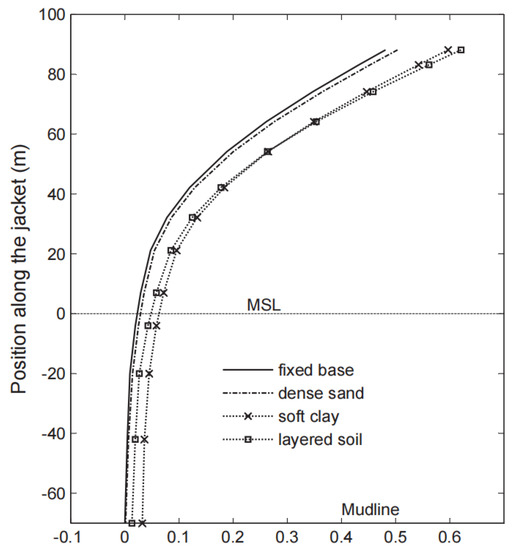
Figure 26.
Influence of SSI in OWT analysis [68].
The upwind flow field is far field potential and disturbance potential φT. The sum of T shows the flow curve of Y = rT and −10rT in Figure 27 (tower radius 0.2 m). On this basis, the unsteady aerodynamic characteristics of the floating wind turbine under platform surge motion are predicted. The aerodynamic characteristics of a floating wind turbine, the stability of releasing eddy current, and aerodynamic stability are analyzed in detail [69]. After the flow has passed through the tower it reattaches, as it is an inviscid ideal potential flow. According to a previous study, the theoretical analysis of the potential flow around a circular cylinder is almost the same as an experimental test in the upwind region and differs from the actual flow thereafter.
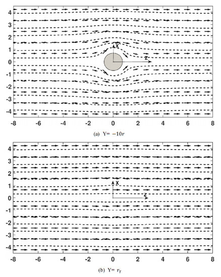
Figure 27.
The streamline distribution at different heights [69]. (a) Streamline field at 10 tower radius lengths down from the turbine. (b) Streamline field at a distance of 1 tower radius length from the turbine upwards.
6. Conclusions
The dynamic parameters of the flexible multi-body system are analyzed to enhance the stability of the wind turbine and prevent structural fracture caused by abnormal dynamic parameters, so as to drive parts for manufacturing wind turbines, optimize the design, research, and development, and drive the growth of manufacturing industry. Wind turbine detection and maintenance can maintain the normal power generation efficiency of wind turbines, so that it gradually becomes a kind of industry. The manufacture of batteries is closely linked with wind power generation, and energy storage has become a research direction. Wind turbine construction in the seaside or grassland, where the scenery is better, can help to develop tourism. The growth of the wind energy industry to promote economic development is effective and feasible.
The sustained growth of technology and the gradual accumulation of wind power operating experience, wind turbine prices, wind farm investment, and operation maintenance costs will bring down the cost of wind power generation. With the market regulation and the integration process having been accelerated, Chinese wind farms and the industry concentrations have gradually improved. Thos promotes acceleration of the integration of the wind power parts industry and the experience of a high-speed development stage of the dynamic response of flexible multi-body large wind turbines that is going through the industry structure optimization adjustment period. Meanwhile, wind turbine blade optimization, pile foundation structure design of wind turbines, and flexible multi-body dynamics need to be studied in the future.
The interaction and coupling between elastic deformation and rotational motion of flexible blades of large wind turbines during their rotation around the axis of the wind turbine is particularly important for the design of their aeroelastic stability and control system. It is the core feature of multi-body system dynamics to study the interaction or coupling between object deformation and rigid body motion and the dynamic effect caused by this coupling. Studying the stability of flexible multi-body system of wind turbines can provide reference value for the normal and stable operation of wind turbines.
Author Contributions
Conceptualization, Z.X. and H.Z.; methodology, Y.J.; software, H.Z.; validation, Z.X., H.Z. and Y.J.; formal analysis, Z.X.; investigation, H.Z.; resources, Y.J.; data curation, Z.X.; writing—original draft preparation, Z.X.; writing—review and editing, Y.J.; visualization, Y.J.; supervision, Z.X.; project administration, Z.X.; funding acquisition, Y.J. All authors have read and agreed to the published version of the manuscript.
Funding
The research was supported by the Program for the Introduction of Foreign Intellects in Hebei Prov (2022) “Research on Key Technologies and Equipment of Efficient and Clean Power Generation for Carbon Neutralization” (No. 20220701).
Institutional Review Board Statement
Not applicable.
Informed Consent Statement
Informed consent was obtained from all subjects involved in the study.
Data Availability Statement
The authors confirm that the data supporting the findings of this study are available within the article.
Conflicts of Interest
The authors declare no conflict of interest.
Abbreviations
| HAWC2 | Horizontal axis wind turbine simulation code second generation |
| WAMIT | Wave analysis MIT |
| CG | Center of gravity |
| FOWT | Floating offshore wind turbine |
| NTM | Normal turbulence model |
| ECD | Extreme coherent gust with direction change |
| VLFS | Very large floating structure |
| CSC | Circular spar concept |
| CTC | CSC-torus-combination |
| VAWT | Vertical axis wind turbine |
| FSI | Fluid–structure interaction |
| CFD | Computational fluid dynamics |
| MBBT | Momentum-based beam theory |
| MCM | Momentum cloud method |
| FWT | Floating wind turbine |
| HAWT | Horizontal-axis wind turbine |
| RBM | Root-bending moment |
| GMPOP | Generalized multi-scale permutation ordinal pattern |
| DMD | Dynamic mode decomposition |
| BTD | Blade tip deflection |
| OWT | Offshore wind turbine |
| EIA | Energy Information Administration |
| IRENA | International Renewable Energy Agency |
| GWEC | Global Wind Energy Council |
| GD | Graph digitizer |
| NACA | National Advisory Committee for Aeronautics |
| ABS | Acrylonitrile butadiene styrene |
| DOF | Degrees of freedom |
| FRF | Frequency response function |
| PLC-B | Planet carrier bearing |
| RNA | Rotor-nacelle assembly |
| EOM | Equation of motion |
| CM | Center of mass |
| MWWC | Mono-WT-WEC Combination |
| WEC | Wave energy converter |
| AQWA | Advanced quantitative wave analysis |
| BEM | Boundary element method |
| NREL | National Renewable Energy Laboratory |
| LSS | Low-speed stage |
| RWT | Reference wind turbine |
| SSI | Soil–structure interaction |
References
- Borg, M.; Hansen, A.; Bredmose, H. Floating substructure flexibility of large-volume 10MW offshore wind turbine platforms in dynamic calculations. J. Phys. Conf. Ser. 2016, 753, 42–52. [Google Scholar] [CrossRef]
- Guo, S.; Li, Y.; Chen, W. Analysis on dynamic interaction between flexible bodies of large-sized wind turbine and its response to random wind loads. Renew. Energy 2020, 163, 123–137. [Google Scholar] [CrossRef]
- Yang, J.; He, Y.-P.; Zhao, Y.-S.; Yang, X.-Y.; Zhang, G.-R. Coupled dynamic response analysis of multi-column floating offshore wind turbine with low center of gravity. J. Ocean Eng. Sci. 2022, 127, 77–91. [Google Scholar] [CrossRef]
- Chen, J.; Liu, Z.; Song, Y.; Peng, Y.; Li, J. Experimental study on dynamic responses of a spar-type floating offshore wind turbine. Renew. Energy 2022, 196, 560–578. [Google Scholar] [CrossRef]
- Sajeer, M.M.; Mitra, A.; Chakraborty, A. Multi-body dynamic analysis of offshore wind turbine considering soil-structure interaction for fatigue design of monopile. Soil Dyn. Earthq. Eng. 2021, 144, 184–203. [Google Scholar] [CrossRef]
- Li, Z.; Gao, Z.; Chen, Y.; Zhang, L.; Wang, J. A novel time-variant prediction model for megawatt flexible wind turbines and its application in NTM and ECD conditions. Renew. Energy 2022, 196, 1158–1169. [Google Scholar] [CrossRef]
- Mitra, A.; Chakraborty, A. Multi-objective optimization of composite airfoil fibre orientation under bending–torsion coupling for improved aerodynamic efficiency of horizontal axis wind turbine blade. J. Wind Eng. Ind. Aerodyn. 2022, 221, 114–135. [Google Scholar] [CrossRef]
- Li, L. Full-coupled analysis of offshore floating wind turbine supported by very large floating structure with consideration of hydroelasticity. Renew. Energy 2022, 189, 790–799. [Google Scholar] [CrossRef]
- Li, Y.; Chen Ong, M.; Wang, K.; Li, L.; Cheng, Z. Power performance and dynamic responses of an integrated system with a semi-submersible wind turbine and four torus-shaped wave energy converters. Ocean Eng. 2022, 259, 111810. [Google Scholar] [CrossRef]
- Natarajan, K.; Madabhushi, G.S. Seismic response of an offshore wind turbine jacket structure with pile foundations. Soil Dyn. Earthq. Eng. 2022, 162, 37–50. [Google Scholar] [CrossRef]
- Hong, S.; Zhang, H.; Nord, T.S.; Halse, K.H. Effect of fender system on the dynamic response of onsite installation of floating offshore wind turbines. Ocean Eng. 2022, 259, 59–73. [Google Scholar] [CrossRef]
- Deng, W.; Yu, Y.; Liu, L.; Guo, Y.; Zhao, H. Research on the dynamical responses of H-type floating VAWT considering the rigid-flexible coupling effect. J. Sound Vib. 2020, 469, 134–155. [Google Scholar] [CrossRef]
- El S. Yassen, Y.; Abdelhameed, A.S.; Elshorbagy, K.A. An examination of hub wind turbine utilizing fluid-structure interaction strategy. Alex. Eng. J. 2022, 254, 235–245. [Google Scholar]
- Tang, S.; Sweetman, B.; Gao, J. Nonlinear effects and dynamic coupling of floating offshore wind turbines using geometrically-exact blades and momentum-based methods. Ocean Eng. 2021, 229, 217–233. [Google Scholar] [CrossRef]
- Wang, S.; Nejad, A.R.; Bachynski, E.E.; Moan, T. Effects of bedplate flexibility on drivetrain dynamics: Case study of a 10 MW spar type floating wind turbine. Renew. Energy 2020, 161, 808–824. [Google Scholar] [CrossRef]
- Leroy, V.; Delacroix, S.; Merrien, A. Experimental investigation of the hydro-elastic response of a spar-type floating offshore wind turbine. Ocean Eng. 2022, 255, 96–109. [Google Scholar] [CrossRef]
- Jokar, H.; Mahzoon, M.; Vatankhah, R. Nonlinear dynamic characteristics of horizontal-axis wind turbine blades including pre-twist. Ocean Eng. 2022, 256, 121–143. [Google Scholar] [CrossRef]
- Li, J.; Wang, Y.; Zhao, X.; Qi, P. Model free adaptive control of large and flexible wind turbine rotors with controllable flaps. Renew. Energy 2021, 180, 68–82. [Google Scholar] [CrossRef]
- Khair Al-Solihat, M.; Nahon, M. Flexiblemultibodydynamic modeling of a floating wind turbine. Int. J. Mech. Sci. 2018, 142, 518–529. [Google Scholar] [CrossRef]
- Wang, Q.; Yu, M.; Li, D.; Li, R. Dynamic stall characteristics of wind turbine airfoil in sand-wind environment. Ocean Eng. 2023, 274, 114080. [Google Scholar] [CrossRef]
- Zhang, H.; Zhang, N.; Cao, X. Conceptualization and dynamic response of an integrated system with a semi-submersible floating wind turbine and two types of wave energy converters. Ocean Eng. 2023, 269, 113517. [Google Scholar] [CrossRef]
- Deng, W.; Guo, Y.; Liu, L.; Li, Y.; Jiang, Y.; Xie, P. Dynamic response analysis of a floating vertical axis wind turbine with helical blades based on the model test. Ocean Eng. 2023, 273, 113930. [Google Scholar] [CrossRef]
- Barooni, M.; Nezhad, S.K.; Ali, N.A.; Ashuri, T.; Sogut, D.V. Numerical study of ice-induced loads and dynamic response analysis for floating offshore wind turbines. Mar. Struct. 2022, 86, 103300. [Google Scholar] [CrossRef]
- Li, N.; Shi, W.; Han, X.; Li, X.; Verma, A.S.; Liu, C. Dynamic analysis of an integrated offshore structure comprising a jacket-supported offshore wind turbine and aquaculture steel cage. Ocean Eng. 2023, 274, 114059. [Google Scholar] [CrossRef]
- Jiang, Z.; Yang, L.; Gao, Z.; Moan, T. Integrated dynamic analysis of a spar floating wind turbine with a hydraulic drivetrain. Renew. Energy 2022, 201, 608–623. [Google Scholar] [CrossRef]
- Shao, K.; He, Y.; Xing, Z.; Du, B. Detecting wind turbine anomalies using nonlinear dynamic parameters-assisted machine learning with normal samples. Reliab. Eng. Syst. Saf. 2023, 233, 109092. [Google Scholar] [CrossRef]
- Zhang, P.; Li, Y.; Tang, Y.; Zhang, R.; Li, H.; Gu, J. Multi-objective optimization and dynamic response predictions of an articulated offshore wind turbine. Ocean Eng. 2023, 273, 114017. [Google Scholar] [CrossRef]
- Yang, S.; Deng, X.; Zhang, M.; Xu, Y. Effect of wave spectral variability on the dynamic response of offshore wind turbine considering soil-pile-structure interaction. Ocean Eng. 2023, 267, 113222. [Google Scholar] [CrossRef]
- Cao, S.; Cheng, Y.; Duan, J.; Fan, X. Experimental investigation on the dynamic response of an innovative semi-submersible floating wind turbine with aquaculture cages. Renew. Energy 2022, 200, 1393–1415. [Google Scholar] [CrossRef]
- Wu, S.; Sun, H.; Zheng, X. A numerical study on dynamic characteristics of 5 MW floating wind turbine under wind-rain conditions. Ocean Eng. 2022, 262, 112095. [Google Scholar] [CrossRef]
- Karbasian, H.R.; Esfahani, J.A.; Aliyu, A.M.; Kim, K.C. Numerical analysis of wind turbines blade in deep dynamic stall. Renew. Energy 2022, 197, 1094–1105. [Google Scholar] [CrossRef]
- Liang, J.; Kato, B.; Wang, Y. Constructing simplified models for dynamic analysis of monopile-supported offshore wind turbines. Ocean Eng. 2023, 271, 113785. [Google Scholar] [CrossRef]
- Chen, R.; Qin, D.; Liu, C. Dynamic modelling and dynamic characteristics of wind turbine transmission gearbox-generator system electromechanical-rigid-flexible coupling. Alex. Eng. J. 2023, 65, 307–325. [Google Scholar] [CrossRef]
- Sun, K.; Xu, Z.; Li, S.; Jin, J.; Wang, P.; Yue, M.; Li, C. Dynamic response analysis of floating wind turbine platform in local fatigue of mooring. Renew. Energy 2023, 204, 733–749. [Google Scholar] [CrossRef]
- Lieng, J.T.; Sturm, H.; Hasselø, K.K. Dynamically installed anchors for floating offshore wind turbines. Ocean Eng. 2022, 266, 112789. [Google Scholar] [CrossRef]
- El Beshbichi, O.; Xing, Y.; Ong, M.C. Comparative dynamic analysis of two-rotor wind turbine on spar-type, semi-submersible, and tension-leg floating platforms. Ocean Eng. 2022, 266, 112926. [Google Scholar] [CrossRef]
- De Cillis, G.; Semeraro, O.; Leonardi, S.; De Palma, P.; Cherubini, S. Dynamic-mode-decomposition of the wake of the NREL-5MW wind turbine impinged by a laminar inflow. Renew. Energy 2022, 199, 1–10. [Google Scholar] [CrossRef]
- Li, B.; Rong, K.; Cai, W.; Shu, S.; Wu, Y. Dynamic response of monopile-supported wind turbines considering non-Gaussian characteristics of wind inflow. Appl. Ocean Res. 2022, 127, 103321. [Google Scholar] [CrossRef]
- Jonkman, J.M. Definition of the Floating System for Phase IV of OC3; Technical Report NREL/TP-500-47535; National Renewable Energy Laboratory: Golden, CO, USA, 2010. [Google Scholar]
- Jonkman, J.M.; Butterfield, S.; Musial, W.; Scott, G. Definition of a 5-MW Reference Wind Turbine for Offshore System Development; Technical Report NREL/TP-500-38060; National Renewable Energy Laboratory: Golden, CO, USA, 2009. [Google Scholar]
- Yuan, J. Wind energy in China estimating the potential. Nat. Energy 2016, 1, 16095. [Google Scholar] [CrossRef]
- Lin, Y.; Tu, L.; Liu, H.; Li, W. Fault analysis of wind turbines in China. Renew. Sustain. Energy Rev. 2016, 55, 482–490. [Google Scholar] [CrossRef]
- Lewis, J.I. Wind energy in China getting more from wind farms. Nat. Energy 2016, 1, 16076. [Google Scholar] [CrossRef]
- Cheng, Y.; Xue, Z.; Wang, W.; Jiang, T.; Wang, Y. Numerical simulation on dynamic response of flexible multi-bodytower blade coupling in large wind turbine. Energy 2018, 152, 601–612. [Google Scholar] [CrossRef]
- Thé, J.; Yu, H. A critical review on the simulations of wind turbine aerodynamics focusing on hybrid RANS-LES methods. Energy 2017, 138, 257–289. [Google Scholar] [CrossRef]
- Chu, Y.-J.; Chong, W.-T. A biomimetic wind turbine inspired by Dryobalanopsaromatica seed: Numerical prediction of rigid rotor blade performance with OpenFOAM®. Comput. Fluids 2017, 159, 295–315. [Google Scholar] [CrossRef]
- Dose, B.; Rahimi, H.; Herraez, I.; Stoevesandt, B.; Peinke, J. Fluid-structure coupled computations of the NREL 5MWwind turbine by means of CFD. Renew. Energy 2018, 129, 591–605. [Google Scholar] [CrossRef]
- Darvishi-Alamouti, S.; Bahaari, M.-R.; Moradi, M. Natural frequency of offshore wind turbines on rigid and flexiblemonopiles in cohesionless soils with linear stiffness distribution. Appl. Ocean Res. 2017, 68, 91–102. [Google Scholar] [CrossRef]
- MacPhee, D.W.; Beyene, A. Performance analysis of a small wind turbine equipped with flexible Blades. Renew. Energy 2019, 132, 497–508. [Google Scholar] [CrossRef]
- Nada, A.A.; Al-Shahrani, A.S. Shape Optimization of Low Speed Wind Turbine Blades using Flexible Multibody Approach. Energy Procedia 2017, 134, 577–587. [Google Scholar] [CrossRef]
- Helsen, J.; Peeters, P.; Vanslambrouck, K.; Vanhollebeke, F.; Desmet, W. The dynamic behavior induced by different wind turbine gearbox suspension methods assessed by means of the flexible multibody technique. Renew. Energy 2014, 69, 336–346. [Google Scholar] [CrossRef]
- Dai, L.; Zhou, Q.; Zhang, Y.; Yao, S.; Kang, S.; Wang, X. Analysis of wind turbine blades aeroelast performance under yaw conditions. J. Wind Eng. Ind. Aerodyn. 2017, 171, 273–287. [Google Scholar] [CrossRef]
- Li, Y.; Castro, A.M.; Sinokrot, T.; Prescott, W.; Carrica, P.M. Coupled multi-body dynamics and CFD for wind turbine simulation including explicit wind turbulence. Renew. Energy 2015, 76, 338–361. [Google Scholar] [CrossRef]
- Ebrahimi, A.; Sekandari, M. Transient response of the flexible blade of horizontal-axis wind turbines in wind gusts and rapid yaw changes. Energy 2018, 145, 261–275. [Google Scholar] [CrossRef]
- Chen, B.; Zhang, Z.; Hua, X.; Basu, B.; Nielsen, S.R. Identification of aerodynamic damping in wind turbine using time-frequency analysis. Mech. Syst. Signal Process. 2017, 91, 198–214. [Google Scholar] [CrossRef]
- Wang, L.; Sweetman, B. Simulation of large-amplitude motion of floating wind turbines using conservation of momentum. Ocean Eng. 2012, 42, 155–164. [Google Scholar] [CrossRef]
- Tang, D.; Bao, S.; Luo, L.; Mao, J.; Lv, B.; Guo, H. Study on the aeroelastic responses of a wind turbine using a coupled multibody-FVW method. Energy 2017, 141, 2300–2313. [Google Scholar] [CrossRef]
- Ren, N.; Ma, Z.; Fan, T.; Zhai, G.; Ou, J. Experimental and numerical study of hydrodynamic responses of a new combined monopile wind turbine and a heave-type wave energy converter under typical operational conditions. Ocean Eng. 2018, 159, 1–8. [Google Scholar] [CrossRef]
- Koukoura, C.; Brown, C.; Natarajan, A.; Vesth, A. Cross-wind fatigue analysis of a full scale offshore wind turbine in the case of wind–wave misalignment. Eng. Struct. 2016, 120, 147–157. [Google Scholar] [CrossRef]
- Alamo, G.M.; Aznarez, J.J.; Padron, L.A.; Martínez-Castro, A.E.; Gallego, R.; Maeso, O. Dynamic soil-structure interaction in offshore wind turbines on monopoles in layered seabed based on real data. Eng. Struct. 2018, 156, 14–24. [Google Scholar]
- Yuan, C.; Chen, J.; Li, J.; Xu, Q. Fragility analysis of large-scale wind turbines under the combination of seismic and aerodynamic loads. Renew. Energy 2017, 113, 1122–1134. [Google Scholar] [CrossRef]
- Mo, W.; Li, D.; Wang, X.; Zhong, C. Aeroelastic coupling analysis of the flexible blade of a wind turbine. Energy 2015, 89, 1001–1009. [Google Scholar] [CrossRef]
- Gallego-Calderon, J.; Natarajan, A. Assessment of wind turbine drive-train fatigue loads under torsional excitation. Eng. Struct. 2015, 103, 189–202. [Google Scholar] [CrossRef]
- Menon, M.; Ponta, F.L. Dynamic aeroelastic behavior of wind turbine rotors in rapid pitchcontrol actions. Renew. Energy 2017, 107, 327–339. [Google Scholar] [CrossRef]
- Gong, K.; Chen, X. Influence of non-Gaussian wind characteristics on wind turbine extreme response Engineering Structures. Eng. Struct. 2014, 59, 727–744. [Google Scholar] [CrossRef]
- Katsanos, E.I.; Sanz, A.A.; Georgakis, C.T.; Thöns, S. Multi-hazard response analysis of a 5MW offshore wind turbine. Procedia Eng. 2017, 199, 3206–3211. [Google Scholar] [CrossRef]
- Lemmer, F.; Raach, S.; Schlipf, D.; Cheng, P.W. Parametric Wave Excitation Model for Floating Wind Turbine. Energy Procedia 2016, 94, 290–305. [Google Scholar] [CrossRef]
- Abhinav, K.; Saha, N. Stochastic response of jacket supported offshore wind turbines for varying soil parameters. Renew. Energy 2017, 101, 550–564. [Google Scholar] [CrossRef]
- Shen, X.; Chen, J.; Hu, P.; Zhu, X.; Du, Z. Study of the unsteady aerodynamics of floating wind turbines. Energy 2018, 145, 793–809. [Google Scholar] [CrossRef]


Disclaimer/Publisher’s Note: The statements, opinions and data contained in all publications are solely those of the individual author(s) and contributor(s) and not of MDPI and/or the editor(s). MDPI and/or the editor(s) disclaim responsibility for any injury to people or property resulting from any ideas, methods, instructions or products referred to in the content. |
© 2023 by the authors. Licensee MDPI, Basel, Switzerland. This article is an open access article distributed under the terms and conditions of the Creative Commons Attribution (CC BY) license (https://creativecommons.org/licenses/by/4.0/).