Article

Design and Numerical Energetic Analysis of a Novel Semi-Automated Biomass-Powered Multipurpose Dryer

1
Department of Mechatronic Engineering, Alex Ekwueme Federal University, Ndufu-Alike, Abakaliki P.O. Box 1010, Nigeria
2
Department of Energy Systems Engineering, Faculty of Integrated Technologies, Universiti Brunei Darussalam, Jalan Tungku Link BE, Bandar Seri Begawan 1410, Brunei
3
Energy Systems Engineering Department, Cyprus International University, Haspolat-Lefkosa, KKTC, Mersin 10, Nicosia 99258, Cyprus
4
Department of Mechanical Engineering, Alex Ekwueme Federal University, Ndufu-Alike, Abakaliki P.O. Box 1010, Nigeria
5
Department of Mechatronic Engineering, Federal University of Technology, Owerri 460114, Nigeria
6
Department of Electronic Engineering, University of Nigeria, Nsukka 410001, Nigeria
7
College of Nuclear Science and Automation Engineering, Chengdu University of Technology, Chengdu 610059, China
*
Author to whom correspondence should be addressed.
Sustainability 2023, 15(8), 6639; https://doi.org/10.3390/su15086639
Submission received: 23 December 2022 / Revised: 6 February 2023 / Accepted: 6 February 2023 / Published: 14 April 2023

Abstract

:
This work presents a new all-inclusive mathematical model that combines both processes and an energy analysis of a semi-automated biomass-powered multipurpose dryer. A mathematical model was developed and a wood sample was used to simulate the model. Energy interaction between the system and sample was established. Most importantly, the incorporation of a sensor control system ensures that, once there is an increase in thermal energy from the combustion of the biomass, a signal is passed to the temperature sensor module that controls the system’s temperature and hence shuts down the heat supply at a predetermined temperature; in this case, at 67 °C. The results of the system’s modification show that the peak temperature of the drying space and the sample was 67 °C and 56 °C, respectively, and that the maximum temperature lag witnessed by the two regimes was 10 °C. The peak temperature removal rate of the sample was 0.0066 kg/h, while the sample attained 0.4 (40%) moisture concentration of its initial value; 90% mass content removal (10% remaining mass content) of the initial mass of the sample was achieved at the end, with a simulation time of 240 s.

1. Introduction

Beyond the limits of memory and recorded history, wood has been of importance to man. It has been used for building structures as well as for making tools and furniture. The drying of materials becomes necessary to ensure adequate preservation and loss prevention [1]. Hence, if water is not removed, timber is not suitable for products that are of good quality. When timbers are well-dried they are user-friendly and, as such, sell at higher amounts than those that have not been dried. Subsequently, the strength of timber is improved when dried and hence avoids infestations as well as ensuring color preservation, weight reduction, and the regulation of contraction [2]. Since most farms produce other materials mentioned above that contain a lot of water, about 50% [3], they need to be dried effectively, such that the water is removed to the required standard. Wood, similar to other materials mentioned, is, therefore, either air-dried or kiln-dried.
Despite the importance of drying in wood processing, the type of technology utilized is even more significant in the process, as are the control methods for product quality [4]. Additionally, the process of drying is energy-intensive for the evaporation of water from wood. The increase in the utilization of kiln drying in recent years is tied to its comparatively improved performance in moisture content removal, which makes wood immediately suitable for applications [5]. Additionally, kiln drying dries wood and other materials better than air drying because the process is controlled for optimal performance. There are many sources of drying employed in recent times that are cost-effective and deployed in areas with little or no electricity supply [6]. Some of these methods consider natural conventions for drying [7]; however, it has been found that some of the downsides of using a natural method such as air include material darkening as well as shrinkage [2]. Different methods are employed depending on the energy requirements [8] and cost implications [9]. A kiln can be seen as a furnace for firing, burning, or drying porcelain or brick. The range of energy required for drying (dependent on wood thickness) using conventional means is between 1870 and 3116 kJ/kg. There is a large body of research [10,11,12] that suggests drying wood in a kiln is superior to drying wood in the open air in terms of both the overall productivity of the timber processing industry and the quality of the timber that is ultimately put to use. In order to keep the final kiln-dried goods viable on the market, this improved productivity and quality of kiln-dried timber, along with the rising cost of traditional fuel (fossil fuel), have spurred the use of renewable energy for wood drying.
The concentration of most research on a solution to open-air drying, as well as on a solution to fading-out traditional fuel methods of drying, is solar dryers [7,13]. Research by Ndukwu et al. [14], made mention of special attention to solar dryers due to their cheap operation and construction costs.
Sustainable drying uses little to no fossil fuels to dry agricultural products. Agricultural products are dried using alternative fuels or energy sources, which could lessen the environmental impact of food drying [15]. Renewable energy technologies have been anticipated to be a good approach for food drying despite some obstacles, and they offer various advantages, such as a cheap cost, high efficiency, expanding employment prospects, etc. The following are the two primary research philosophies for sustainable food drying: increasing the dryer’s efficiency, which can be carried out by insulating it, recovering heat from it, recirculating air, and changing the operational parameters of the systems, and by using combined heat and power (CHP), biomass-derived fuels, and other renewable energy sources to enhance or replace the system’s energy supply [16]. A large portion of literature on sustainable drying is dedicated to solar drying; however, despite the immense potential of solar drying, its major drawback is the intermittence of the process due to low or no insolation at night periods, which causes subpar dried goods. Most studies have tried to solve the issue of the intermittence of solar dryers by utilizing thermal storage, with a few studies analyzing the hybridizing of solar dryers with biomass. A study by [17] analyzed the use of solar heaters with thermal storage as dryers for aiding the drying process, even during the night time. Their results showed that, upon incorporating a thermal mass, the drying process continued even at night. A similar study by [18] added storage materials underneath a flat-plate solar heater to improve the drying process, and their experimental analysis showed that the drying period was reduced. Though these studies showed improvements in the drying process by incorporating thermal storage, there is still the challenge of the low intensity of solar radiation, which only allows for a minimal increase in the thermal mass, hence causing the dehydration process to be insignificant [19].
A veritable solution of using biomass as a backup for solar dryers has been analyzed by a few studies in the literature. A study by Prasad and Vijay [20] investigated a solar–biomass dryer. The top of the biomass burner features a rock slab that assists in regulating the drying air’s temperature. These dryer models contain a backup heater but no thermal storage for solar energy collection. After sundown, the drying chamber’s air temperature decreases to ambient, needing backup heating even on sunny days. This results in the waste of fuel and solar resources.
In most underdeveloped nations, biomass (particularly fuelwood) is a major energy source and is frequently burned using ineffective means. The potential of biomass is huge in terms of it being an energy resource for the drying process [21], either used alone or as backup for the solar drying process; however, biomass-powered drying processes are almost nonexistent in the literature. This study seeks to cover this huge gap in the literature by presenting a new all-inclusive mathematical model that combines both processes and an energy analysis of a semi-automated biomass-powered multipurpose dryer.
A biomass kiln dryer is a heated chamber or oven in which cut lumber is dried and seasoned. It has, as its major focus, the design and manufacture of wood drying (kiln) using the natural convection of air and heat flow, making biomass the heat source. Again, it is important to improve the drying chambers and systems depending on heat requirements and the hardness as well as softness of the wood [22]. It has been observed that most conventional methods present some error margins [23]. Some authors have reported on the simulation of biomass kiln dryers over the past decades. Prominent amongst them include Steinmann, [24], Holmberg and Ahtila [25], and Eriksson et al. [26]. Steinmann [24], in his years of experience, developed a real-time simulation system. Eriksson et al., [26] presented a unified transport model that considers diverse wetness phases. Numerical simulation using a finite method approach to predict the average moisture content in spruce was used. The simulations agreed reasonably well with the experimentally measured values. Holmberg and Ahtila [25], modeled the bark drying process in a continuous cross-flow dryer. The model included the use of secondary heat sources from plants for dry air heating. The developed calculation model was utilized to establish the last fuel humidity content, drying temperature, and degree of energy efficiency of the dryer [27].
With the overdependence on electric and solar energy for wood drying, especially in most developing nations, it becomes necessary to develop a biomass-powered system that would be optimal, cost-effective, and have high overall system efficiency. There are a couple of reasons why numerical modeling and simulations were adopted in this study: First, for the improvement of the efficiency and effectiveness of the system. Secondly, to measure the variability in wood properties in a consistent numerical method, allowing for the improvement of the overall system. Thirdly, it has been observed that conventional drying devices that function based on test trials and the application of know-how take significant time, huge financial resources, and experimental machineries to sufficiently ensure the reliability of the system before production. However, the literature review shows that there is presently no strong technical base for conclusions in relation to several designs presented in the literature and their results globally. This, therefore, necessitated the study of a biomass dryer, using mathematical algorithms to enhance its productivity and performance, subsequently arriving at a criterion that would enable the adequate evaluation of the system’s operations. The drying of biomass’s ability to increase global temperatures is 9.2 kg CO2-e/t of biomass dried in an oven. It is assumed that wood waste is used as fuel and that a belt dryer is used for drying. Due to fuel switching, there is large potential to reduce CO2 emissions from a typical black-coal-fired power plant if this dry biomass is employed in a power plant as fuel for a steam boiler. This is presuming that trees are grown to sustainably produce this biomass.
Therefore, this study presents a novel improvement of a far-reaching prototype for dryers, incorporating temperature control mechanisms as well as establishing energy interactions and the behavior of woods within the system during operation. In this study, a wood sample of 100,000 cm3 was used as a simulation of the model for the determination of the temperature and energy interaction within the dryer during the natural convective drying process.

2. Materials and Methods

A mathematical model was developed and a wood sample of (25 × 40 × 100) cm3 was used for the simulation of the model for the determination of the temperature and energy interaction within the dryer during the natural convective drying process [28]. A sensor control system was incorporated to ensure that, once there is an increase in thermal energy from the combustion of the biomass, a signal is passed to the temperature sensor module that controls the system’s temperature and hence shuts down the heat supply at a predetermined temperature. This would help in monitoring and controlling the drying rate of the sample. To generate these models, a lumped system thermal analysis was adopted.
Figure 1 shows the semi-automated multipurpose dryer with a sensor incorporated to regulate the temperature regime. The system’s sensor controls the upper temperature limit of 67 °C to ensure gradual and smooth drying. During its drying operation, the sensor ensures that an increase in thermal energy from the combustion of the biomass ignites a signal and transmits the same to the temperature sensor module that controls, thereby cutting off the heat supply on the attainment of 67 °C.

2.1. Drying Chamber and Sample Temporal Temperature Regime Formulation

For the biomass dryer, the heat generation rate (power), Qg, can be given as follows:
Q g = m ˙ C v
where m ˙ is the combustion rate of the biomass and C v = the biomass calorific value.
However, the energy generation rate of the biomass can be related to the internal energy changing rate of the system as applicable to the rate of thermal energy content change. The combustion chamber of the dryer is assumed to be constantly and fully fed with biomass. Hence:
Q g = ρ C p V d T d t
where T = the system’s temperature, V = the volume of the biomass combustion chamber, ρ is the material’s density, Cp = the material’s specific heat capacity, and t equals the time of the heating of the system. The generated heat is transferred through the convective heat flow process; therefore, we can adopt a transient lumped system heat analysis process in obtaining the temporal temperature variation in the combustion chamber. Hence:
Q g = h A ( T T o ) = ρ C p V d T d t
To simplify (3), we have the following:
d T ( T T o ) = h A ρ C p V d t
Integrating (4) yields the following:
ln ( T T o ) = h A ρ C p V t + K
where K is the constant of integration. As an initial value problem (IVP), the initial condition (IC) can be expressed as follows:
T t = 0 = T i
where Ti = the chamber’s initial temperature. Applying the IC:
ln ( T i T o ) = K
Substituting (6) into (7) with simplification yields the following:
T T o T i T o = exp [ ( h A ρ C p V ) t ]
T = T o + ( T i T o ) exp [ ( h A ρ C p V ) t ]
In Equation (8), ρ C p V represents the thermal capacitance (Cth) of the material while 1 h A is the thermal resistance (Rth) of the material. Hence, Equation (9) can be expressed as follows:
T T o T i T o = exp ( t C t h R t h )
Equation (10) can be expressed as follows:
θ = θ i exp ( t C t h R t h )
Cth and Rth are analogous to the capacitance (Ce) and resistance (Re) of the electrical system. Where the chamber temporal temperature (at any time, t) is given as   T = θ + T o and θ i = T i T o , Equation (9) can also be expressed as a function of dimensionless parameters, hence:
θ = θ i exp ( B i F o )
where Bi is the Biot number and Fo is the Fourier number. Bi and Fo are expressed as follows:
B i = h L c λ ; F o = k t ρ C p L c 2
where Lc is the characteristic height of the combustion chamber, which is expressed as L c = d 2 , and d is the mid-diameter of the combustion chamber.
The convective heat transfer coefficient, h, is given as follows:
h = N u l λ l
where λ = the thermal conductivity of convective air within the dryer and Nui is the Nusselt number. The Nusselt number is given as follows:
N u l = 0.14 R a l 1 3 ( 1 + 0.0107 P r 1 + 0.01 P r )
Pr = the Prandtl number and R a l = the Raleigh number. R a l is given by R a l = G r i P r ; Pr = υ α ; β = 1 T o ; υ = μ ρ ; and G r i = g β Δ T l 3 υ 2 .
With the adopted lumped system thermal analysis, and considering that the system is well-insulated, there will be less of a temperature drop in the process of heat transfer from the heat source. This temperature drop is a result of both convective and radiative thermal resistance, Rcv and Rrt, respectively; hence, the temperature of the heat generator and the dryer will continue to vary until thermal equilibrium is attained. At any time, the instantaneous heat interaction per unit volume within the dryer is expressed as follows:
ρ C p T = ρ b C p b T b + T T b R t h
where ρ b , C p b , and T b are density, specific heat capacity, and the instantaneous temperature of the oven, respectively, while Rth is the overall thermal resistance, given as follows:
R t h = R c v R r t R c v + R r t
where R c v = 1 A h and R r t = 1 A h r .
h had been defined in Equation (13) and hr = the heat transfer radiation coefficient, given as follows:
h r = A σ ( T 2 + T b 2 ) ( T + T b ) 1 ε s + 1 ε b 1
where εs and εb are the emissivity of the sources of heat and the dryer, respectively.
To acquire the temperature of the oven at any time (Tb) as a function of the temperature drop factor, Td, Equation (15) is simplified. After the elaborate simplification of Equation (15), Tb is expressed as follows:
T b = T d T
where Td is given as follows:
T d = ( R t h ρ C p 1 R t h ρ b C p b 1 )
Since the temperature variation in the heat generator was considered to be transient, the temperature variation within the drying materials in the dryer will also be considered to be unsteady since its temperature change is a function of that of the heat generator. This can be derived from the evaluated temperature of the dryer, Tb. Hence:
T b = ( R t h ρ C p 1 R t h ρ b C p b 1 ) { T o + ( T i T o ) exp [ ( h A ρ C p V ) t ] }

2.2. Biomass and System Energy and Efficiency

Therefore, the generated energy from the pelleted biomass over the period, t, can be given as follows:
E i n = m C v
m is the mass depletion rate due to the combustion of the biomass pellet (kg), and C v is the biomass calorific value (MJ/kg). The energy expended by the biomass over the period, t, can be given as follows:
E e x p = ρ C p V ( T T i )
The absorbed energy by the drying materials over the period, t, can be given as follows:
E u = ρ b C p b V ( T b T i )
The efficiency of the system, η s , is given as follows:
η s = E u E i n
The expended biomass energy-based efficiency, η b , is given as follows:
η b = E e x p E i n

2.3. Temporal Evaporation Rate

The design shows a dryer compartment that was flawlessly insulated; therefore, the inside energy increase/unit mass of the material equals the thermal energy needed for the vaporization of its unit water content of the drying material:
h c A s ( T b   T i ) =   m ˙ h f g w =   h D A s ( C b   C a ) h f g w
h D equals the coefficient of mass transfer, A s equals the external area of heat as well as the mass transfer, m ˙ represents the frequency of moisture vaporization, h f g w shows the latent heat with which the dampness evaporates, C b equals the temporal moisture concentration of the surface, and C a represents moisture concentration when first exposed to air. In the case of a great temperature in the drying compartment when drying is taking place, which would consequently make the temporary wetness of the component act in a similar fashion to an ideal gas inside the compartment, which also depends on the initial variation in a presumed constant temperature and pressure, then the concentration of the moisture could reflect the change in the temperature inside the dryer. Therefore, its heat transfer could be linked to the energy needed for mass transfer. In Equation (26), the rate at which moisture is removed can be expressed as follows:
m ˙ =   h c A s ( T b   T a ) h f g w  
The difference in initial moisture concentration can be deduced using Equation (28):
C b   C a = h c ( T b   T a ) h D h f g w    
From Equation (26):
h c h D =   ρ C p ( S c P r ) 2 3 =   ρ C p ( L e ) 2 3  
where L e = the Lewis number given by ( D ) . Solving Equation (28) into Equation (29) provides the following:
C b   = C a +   ρ C p ( L e ) 2 3 ( T b   T a ) h f g w    
If C a is presumed to be zero (very low wetness):
C b   = ρ C p ( L e ) 2 3 ( T b   T a ) h f g w    
On the surface, heat, mass, and momentum movements happen concurrently inside the compartment turbulently. Using the Chilton–Colburn J-factor to determine the relationship:
j H =   j D =   C f 2  
Equation (32) can also mean the similarity of momentum, heat, and mass transfer, while C f shows its skin factor of friction; in a scenario of a flow on a flat plate, such as this design, it is represented as follows:
C f =   1.288 R e L 1 2   ( for   laminar   case )
C f =   0.074 R e L 0.2   ( for   turbulent   cases )
It is noteworthy that j H =   h c ρ v C p , a P r 2 3 and j D =   h D v S c 2 3 . With flows across a plate that is flat, the transfer coefficient of heat, h c , is as follows:
h c =   0.037 R e L 1 5 ρ v C p , a P r 2 3  
h r = ε σ ( T b + T a ) ( T b 2 + T a 2 )  
Mathematically, the mass diffusion coefficient, h D , is as follows:
h D =   0.037   v   R e L 1 5 S c 2 3  
where ρ = the density of air, v = the velocity of air, and C p , a = the air-specific heat capacity. The Reynold number = R e L , the Prandtl number equals P r , and the Schmidt number = S c . All are shown below:
R e L =   ρ v L μ ; Pr =   C p , a   μ k ; S c =   𝓋 D
where μ = the absolute viscosity of air, 𝓋 = the air kinematic viscosity, and L = the length of the heat flow surface.

2.4. Thermal Sensor Activation

In other to control the dryer temperature, drying rate, and the system’s general operation, a sensor was incorporated into the system. The system was meant to be controlled to an upper temperature limit of 67 °C to ensure the gradual and smooth drying of the material. The sensor-incorporated system flow diagram is shown in Figure 2. The increase in thermal energy from the combustion of biomass increased the temperature of the system. This signal is passed to the temperature sensor module, which controls the system temperature and hence shuts down the heat supply upon reaching a temperature of 67 °C. This is to ensure the gradual drying of the element to avoid system overheating.
Figure 3 shows the closed loop of the smart multipurpose dryer, with the ambient temperature and other combustion variables as the input signal to the biomass combustion. The heat control unit (HCU) receives this signal and passes it to the drying elements after scrutinizing the possible error signals. Other variables, such as temporal temperature and concentration profiles, energy, and moisture removal rate, are the system outputs. Before the outputs, the signal is sent to the thermal sensor for proper signaling and filtering, which could then be sent back as feedback mechanisms or continuous processing.

3. Results and Discussions

At first, the materials from the onset of drying with the drying chamber were, respectively, maintained at temperatures of 26.5 °C and 30.8 °C. A small wood of 25 cm × 40 cm × 100 cm was used for the simulation. The metallurgical stability and material properties of the wood were considered not to be severely affected, hence the incorporation of the temperature-controlled sensor.
Figure 4 shows the plot of the dryer and its sample drying material. It could be observed from the graph that the drying process was gradual, with the dryer and sample temperatures, respectively, maintained at 67 °C and 56 °C as the peak. The temperature regime of the system also followed the exponential function (as explained in Section 2), and the peak temperature control by the sensor is to ensure that the material’s thermophysical properties remain intact. This, however, shows that at every point in the system the dryer maintains a higher temperature than the material being dried as a result of convection, radiation, thermal resistance, and agitation around the drying chamber.
Figure 5 shows the temporal temperature lag and drying sample temperature regime. The sample at the early period of the process maintained a temperature of 26 °C. The temporal temperature lag regime shows the temporal temperature difference between the drying chamber and the sample as contributed by thermal resistance and agitation. In the graph, the temporal temperature lag maintains a steady increase until it peaks at 10 °C, when the system was brought under control by the sensor. Again, the drying sample increases gradually until it reaches the peak at 56 °C. This result shows that, at every point in the system, the temporal temperature lag maintains a gradual increase due to a drop in intermolecular agitation within the material with a subsequent moisture drop within the material.
Figure 6 shows the result of temporal temperature with the corresponding rate at which moisture is removed from the drying sample. In the graph, the temporal temperature increases gradually till it reaches a peak at approximately 56 °C. The temporal removal rate of the sample dried gradually increases in a close range from 0.0002 kg/h at the initial stage to 0.0066 kg/h at the corresponding sample peak temperature of 56 °C. This graph shows that the drying sample moisture removal rate is also controlled by the sensor according to the model in Equation (26); however, at some point in the system the temporal moisture content remains steady at a very low level for the thermophysical stability of the sample.
Figure 7 shows the result of the temporal moisture removal rate and the corresponding temporal fractional remaining moisture of the drying sample against time. The moisture removal rate increases gradually until it reaches the peak (0.0066 kg/h). The fractional remaining moisture decreases gradually until it falls or drops to 0.40 (40%) of the earlier vapor content of the drying material, which is about 10% of the sample contents; however, this shows that the rate at which moisture is removed behaves oppositely from the fractional remaining moisture of the drying sample, and both regimes coincide at 3 h of the drying time, indicating a moderate drying rate as the flow is controlled by the incorporated sensor.
Figure 8 shows the result of the temporal energy released by biomass and the temporal absorbed energy by drying the sample against drying time. The drying sample during the initial drying time maintained the absorbed energy of 6.7 kJ. In the graph, the biomass witnessed a gradual increase in absorbed energy from 20 kJ until it reaches the peak at 140 kJ, when the system was brought under control by the sensor. The dried sample’s temporal absorbed energy regime maintains an exponential flow and later gradually increases until it reaches the peak at 106.5 kJ; however, at every point in a system the biomass energy maintains higher energy than the absorbed sample dried as some of the thermal energy is lost, even though energy lost was minimized through insulation and the use of highly reflective coating material on the drying chamber surface. Hence, excessive energy lag was not recorded for the two regimes. The gross energy released and absorbed by the biomass as well as the drying sample is, respectively, 120 kJ and 99.8 kJ (approximately 100 kJ). This implies that approximately 20 kJ of the generated energy was lost.
Figure 9 shows the result of biomass-based and system efficiency against drying time. The drying sample efficiency increases gradually at the early stage from the start of the drying from 1% until it reaches the peak at 50%, which was attained correspondingly at above 60% moisture content, after which it drops with the activation of the thermal sensor. The biomass combustion energy release gradually increases from its initial percentage value of 10% until it reaches the peak at 69.4% with the system deactivation by the thermal sensor; however, the lag in the efficiency of biomass energy and that of the system based on the drying rate of the sample is with that of their energy regime due to the energy loss minimization measures and sensor control incorporated in the system.

4. Conclusions

In this study, a new all-inclusive mathematical model for the design of a biomass-powered multipurpose dryer is presented. Mathematical models have also been developed to evaluate the temporal temperature, drying rate, expended energy, and efficiency of the system based on both biomass combustion and the moisture evaporation rate. In developing these numerical models, a lumped system thermal analysis was adopted with the consideration that the system was well-insulated to avoid a drop in temperature in the process of heat transfer from the heat source. A wood sample of (25 × 40 × 100) cm3 was used for the simulation of the model, and a temperature- as well as moisture-controlled sensor was incorporated into the system. The highlights of the designed machine are as follows:
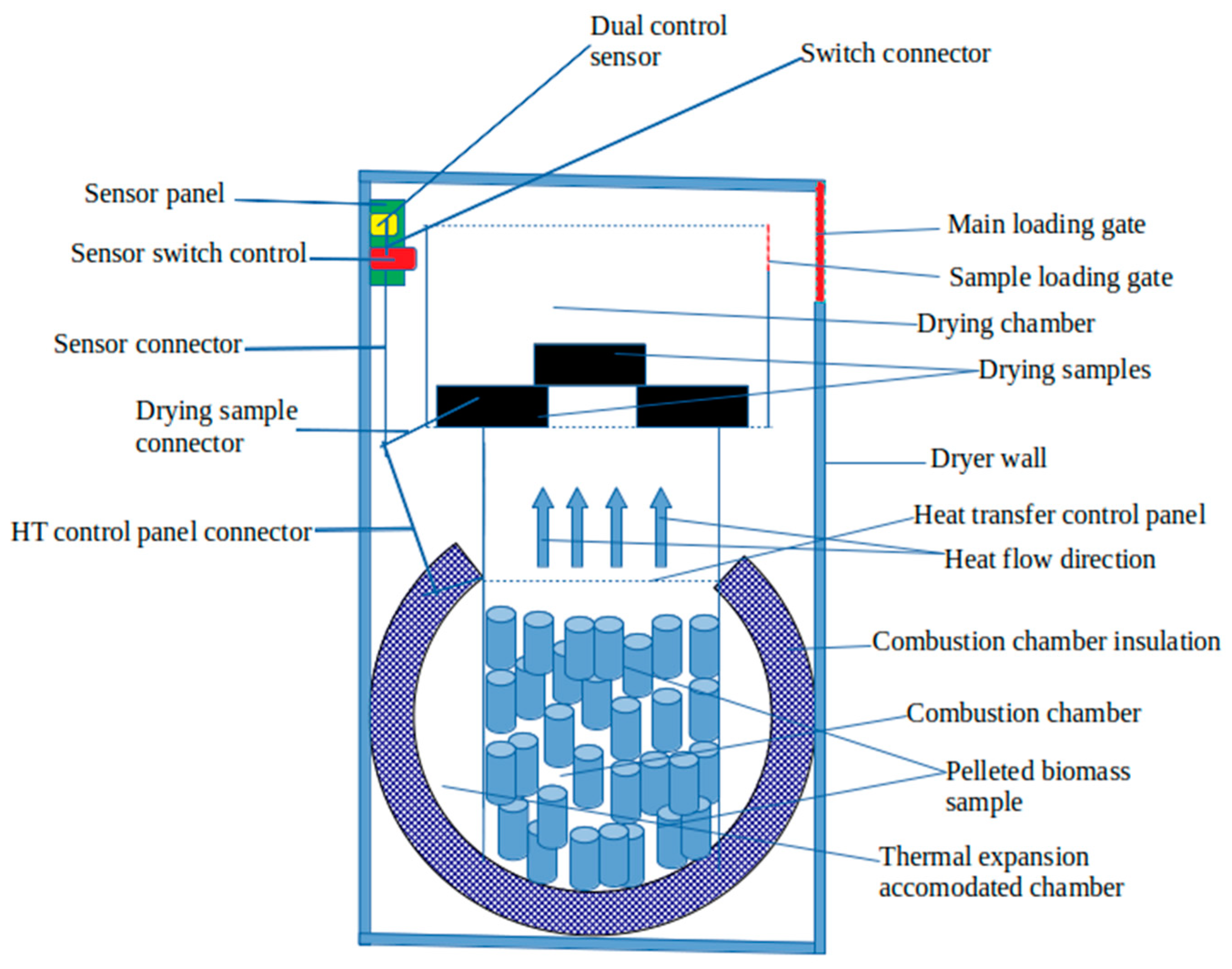
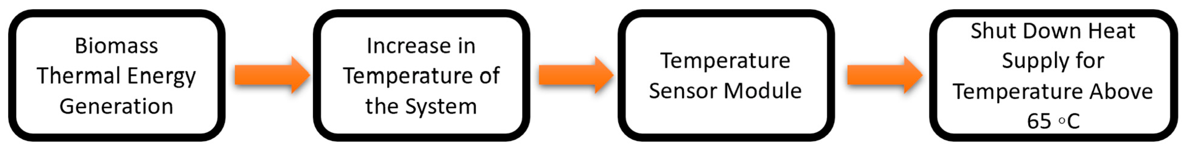
  • The incorporation of the sensor control mechanism was to ensure that, once there is an increase in thermal energy from the combustion of the biomass, a signal is passed to the temperature sensor module, which controls the system’s temperature and hence shuts down the heat supply at a predetermined temperature. This would help in monitoring and controlling the drying rate of the sample.
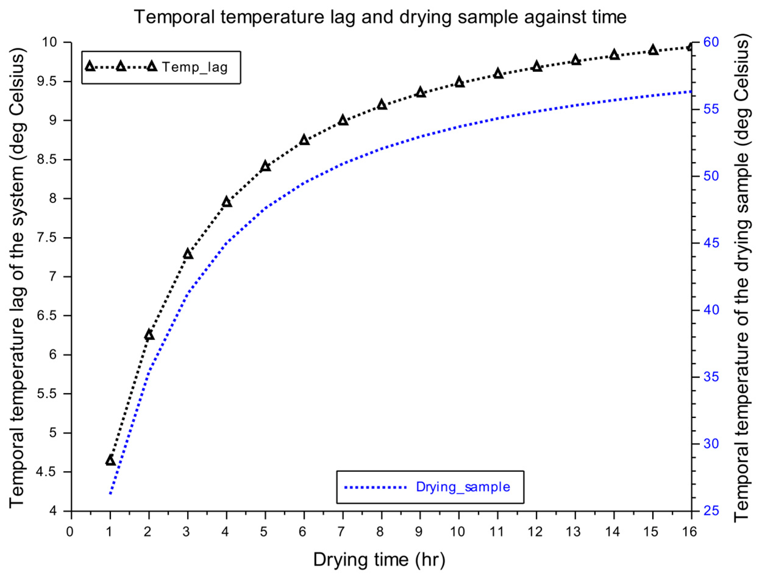
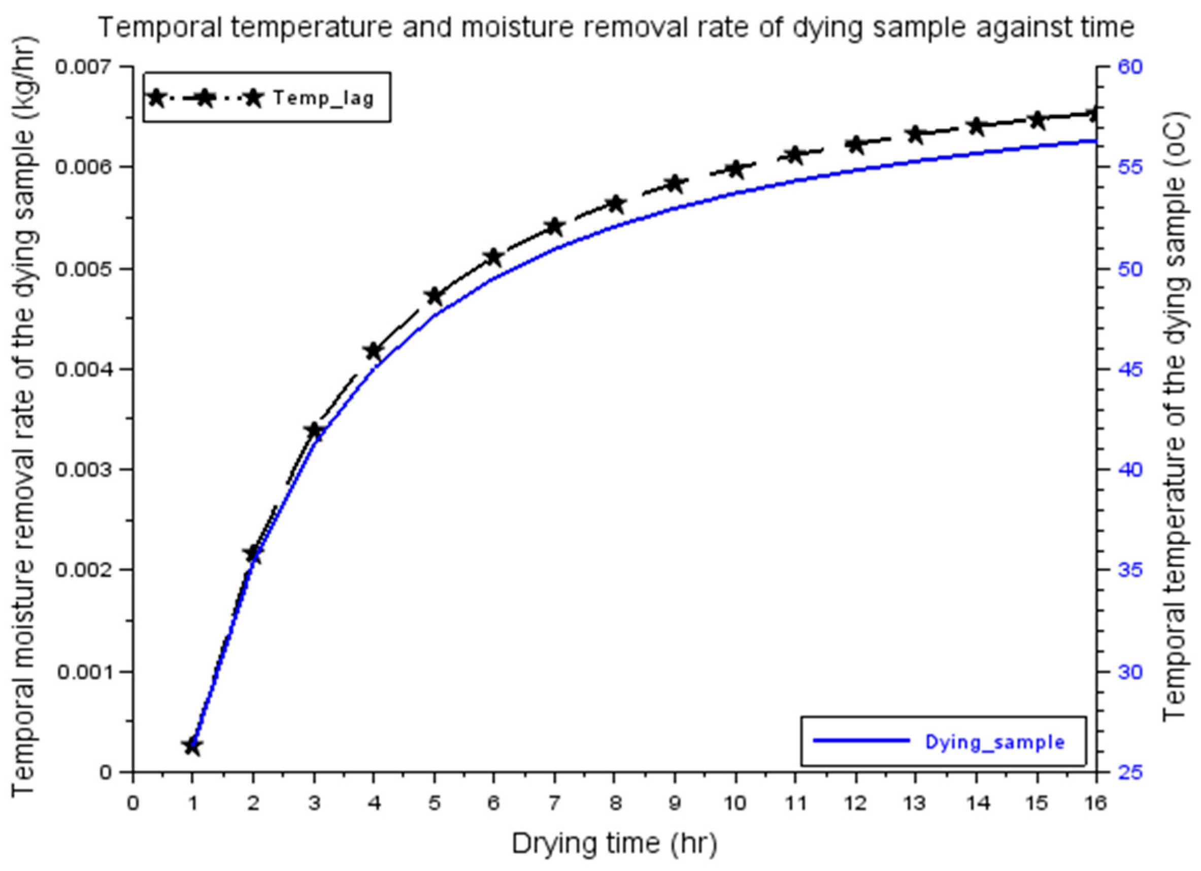
  • The results of the simulation show that the peak temperature of the drying chamber and that of the sample was 67 °C and 56 °C, respectively, and the maximum temperature lag witnessed by the two regimes was 10 °C. The peak temperature removal rate of the sample was 0.0066 kg/h, while the sample attained 0.4 (40%) moisture concentration of its initial value; 90% mass content removal (10% remaining mass content) of the initial mass of the sample was achieved at the end of the simulation.
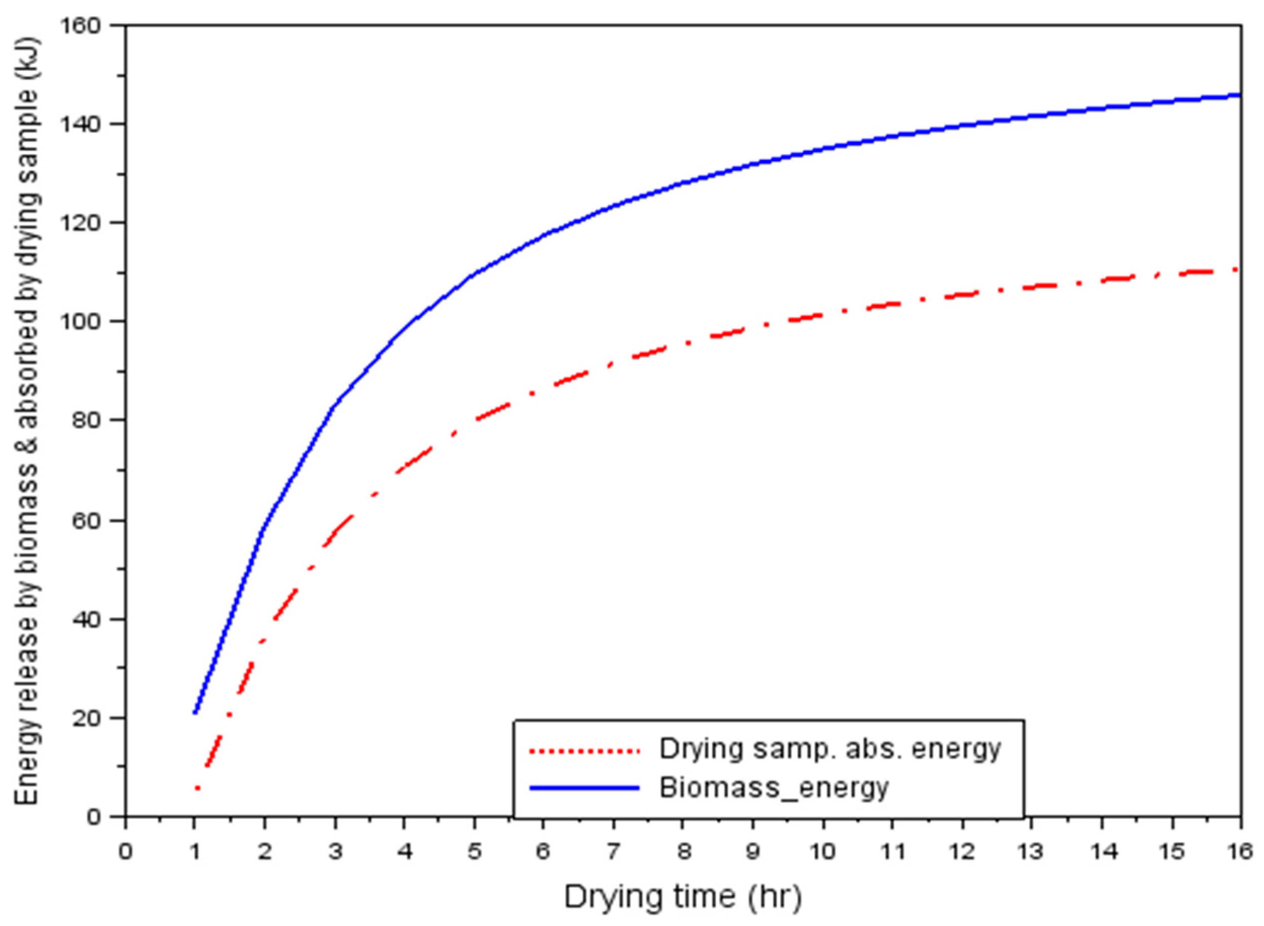
  • The gross energy released and absorbed by the biomass and the drying sample was 120 kJ and 99.8 kJ, respectively (approximately 100 kJ), implying less energy loss; the peak energy efficiency of the biomass and the system based on the drying rate was 69.4% and 50%, respectively. Therefore, the biomass-powered multipurpose dryer, when incorporated with a sensor, is highly effective in achieving gradual and smooth drying with little or no thermophysical effect.
  • This research was a design modification, mathematical modeling, and analysis of energy interaction within an existing system.
It is recommended that, in subsequent studies, a system analysis using experimental results be applied in validating the established model.

Author Contributions

Conceptualization, B.O.E.; methodology, B.O.E. and S.A.A.; formal analysis, B.O.E., M.A., H.A. and U.N.N.; investigation, C.A.O. and U.N.N.; resources, C.A.O.; data curation, J.H.Z.; writing—original draft, S.A.A., H.A. and O.B.; visualization, U.N.N.; supervision, M.A., O.B. and J.H.Z.; project administration, C.A.O.; funding acquisition, J.H.Z. All authors have read and agreed to the published version of the manuscript.

Funding

This work was supported by the Universiti Brunei Darussalam under grant number UBD/RSCH/1.3/FICBF(b)/2022/017.

Institutional Review Board Statement

Not applicable.

Informed Consent Statement

Not applicable.

Data Availability Statement

Not applicable..

Conflicts of Interest

The authors declare no conflict of interest.

References

  1. Ezurike, B.O.; Ajah, S.A.; Ezurike, O.; Nwokenkwo, U. Design and Analysis of Energy and Exergy Performance of an LPG-Powered Fish Drying Machine. J. Kejuruter. 2022, 34, 117–129. [Google Scholar] [CrossRef]
  2. Lee, J.H.; Zuo, L. Mathematical modeling on vacuum drying of Zizyphus jujuba Miller slices. J. Food Sci. Technol. 2011, 50, 115–121. [Google Scholar] [CrossRef] [PubMed] [Green Version]
  3. Desch, H.E.; Dinwoodie, J.M. Timber: Structure, Properties, Conversion and Use, 7th ed.; Macmillan Press Ltd.: London, UK, 1996; 306p. [Google Scholar]
  4. Pirasteh, G.; Saidur, R.; Rahman, S.M.A.; Rahim, N.A. A review on development of solar drying applications. Renew. Sustain. Energy Rev. 2014, 31, 133–148. [Google Scholar] [CrossRef]
  5. Hasan, M.; Langrish, T.A.G. Performance Comparison of Two Solar Kiln Designs for Wood Drying Using a Numerical Simulation. Dry. Technol. 2014, 33, 634–645. [Google Scholar] [CrossRef]
  6. Bond, B.; Espinoza, O.; Araman, P. Design and Operation of a Solar-Heated Dry Kiln for Tropical Latitudes; General Technical Report–Southern Research Station, USDA Forest Service (SRS-134); USDA: Washington, DC, USA, 2011; p. 14.
  7. Hasan, M.; Langrish, T.A.G. Embodied Energy and Carbon Analysis of Solar Kilns for Wood Drying. Dry. Technol. 2014, 33, 973–985. [Google Scholar] [CrossRef]
  8. Steinmann, D.E.; Vernmaas, H.F.; Forrer, J.B. Solar Timber Drying Kilns: Part 1: Review of previous systems and control measures and description of an automated solar kiln. J. Inst. Wood Sci. 1980, 48, 254–257. [Google Scholar]
  9. Salin, J.-G.; Wamming, T. Drying of timber in progressive kilns: Simulation, quality, energy consumption and drying cost considerations. Wood Mater. Sci. Eng. 2008, 3, 12–20. [Google Scholar] [CrossRef]
  10. Chadwick, W.B.; Langrish, T.A.G. A Comparison of Drying Time and Timber Quality in the Contihuous and Cyclic Drying of Australian Turpentine Timber. Dry. Technol. 1996, 14, 895–906. [Google Scholar] [CrossRef]
  11. Helwa, N.H.; Khater, H.; Enayet, M.M.; Hashish, M.I. Experimental Evaluation of Solar Kiln for Drying Wood. Dry. Technol. 2004, 22, 703–717. [Google Scholar] [CrossRef]
  12. Langrish, T.A.G.; Thompson, F.; Plumptre, R.A. Improving the Quality of Timber from Red Beech (N. Fosca) by Intermittent Drying. Dry. Technol. 1992, 10, 947–960. [Google Scholar] [CrossRef]
  13. Prakash, O.; Laguri, V.; Pandey, A.; Kumar, A.; Kumar, A. Review on various modelling techniques for the solar dryers. Renew. Sustain. Energy Rev. 2016, 62, 396–417. [Google Scholar] [CrossRef]
  14. Ndukwu, M.; Onyenwigwe, D.; Abam, F.; Eke, A.; Dirioha, C. Development of a low-cost wind-powered active solar dryer integrated with glycerol as thermal storage. Renew. Energy 2020, 154, 553–568. [Google Scholar] [CrossRef]
  15. Jeswani, H.K.; Burkinshaw, R.; Azapagic, A. Environmental sustainability issues in the food–energy–water nexus: Breakfast cereals and snacks. Sustain. Prod. Consum. 2015, 2, 17–28. [Google Scholar] [CrossRef]
  16. Lamidi, R.O.; Jiang, L.; Pathare, P.B.; Wang, Y.; Roskilly, A. Recent advances in sustainable drying of agricultural produce: A review. Appl. Energy 2018, 233–234, 367–385. [Google Scholar] [CrossRef] [Green Version]
  17. Aboul-Enein, S.; El-Sebaii, A.; Ramadan, M.; El-Gohary, H. Parametric study of a solar air heater with and without thermal storage for solar drying applications. Renew. Energy 2000, 21, 505–522. [Google Scholar] [CrossRef]
  18. El-Sebaii, A.; Aboul-Enein, S.; Ramadan, M.; El-Gohary, H. Experimental investigation of an indirect type natural convection solar dryer. Energy Convers. Manag. 2002, 43, 2251–2266. [Google Scholar] [CrossRef]
  19. Madhlopa, A.; Ngwalo, G. Solar dryer with thermal storage and biomass-backup heater. Sol. Energy 2007, 81, 449–462. [Google Scholar] [CrossRef] [Green Version]
  20. Prasad, J.; Vijay, V.K. Experimental Studies on Drying of Zingiber Officinale, Curcuma Longa l. and Tinospora Cordifolia in Solar-Biomass Hybrid Drier. Renew. Energy 2005, 30, 2097–2109. [Google Scholar] [CrossRef]
  21. Demirbas, A. Potential applications of renewable energy sources, biomass combustion problems in boiler power systems and combustion related environmental issues. Prog. Energy Combust. Sci. 2005, 31, 171–192. [Google Scholar] [CrossRef]
  22. Cai, L.; Oliveira, L.C. Experimental evaluation and modeling of high temperature drying of sub-alpine fir. Wood Sci. Technol. 2009, 44, 243–252. [Google Scholar] [CrossRef]
  23. Langrish, T.A.G.; Thompson, F.; Plumptre, R.A. Measurement of energy flows around a solar kiln used for drying timber. Commonw. For. Rev. 1993, 72, 95–104. [Google Scholar]
  24. Steinmann, D. Real-time simulation of solar kiln drying of timber. Sol. Energy 1995, 54, 309–315. [Google Scholar] [CrossRef]
  25. Holmberg, H.; Ahtila, P. Optimization of the bark drying process in combined heat and power production of pulp and paper mill. In Proceedings of the 3rd Nordic Drying Conference, Karlstad, Sweden, 15–17 June 2005. [Google Scholar]
  26. Eriksson, J.; Johansson, H.; Danvind, J. A Mass Transport Model for Drying Wood under Isothermal Conditions. Dry. Technol. 2007, 25, 433–439. [Google Scholar] [CrossRef]
  27. Ratnasingam, J.; Grohmann, R. Superheated steam application to optimize the kiln drying of rubberwood (Hevea brasiliensis). Eur. J. Wood Wood Prod. 2015, 73, 407–409. [Google Scholar] [CrossRef]
  28. Everett, B. The Development and Simulation of a Mathematical Model for the Drying of Hardwood Timbers in an Australian Solar Kiln. Bachelor Thesis, Department of Chemical Engineering, University of Sydney, Sydney, Australia, 2001; 210p. [Google Scholar]
Figure 1. Semi-automated multipurpose dryer.
Sustainability 15 06639 g001
Figure 2. Sensor-incorporated multipurpose dryer flow diagram.
Sustainability 15 06639 g002
Figure 3. Elements of the closed loop of a semi-automated multipurpose dryer system, where T(t) is the time-dependent temperature from the biomass combustion as input in °C, Z(t) is the time-dependent possible errors within the system, especially during heat control, and Y(t) is the time-dependent output feedback of the system.
Sustainability 15 06639 g003
Figure 4. Dryer temporal variation.
Sustainability 15 06639 g004
Figure 5. Temporal temperature lag and drying sample.
Sustainability 15 06639 g005
Figure 6. Temporal moisture removal rate of drying sample.
Sustainability 15 06639 g006
Figure 7. Fractional remaining moisture of the drying sample.
Sustainability 15 06639 g007
Figure 8. Energy released by biomass and absorbed by drying the sample.
Sustainability 15 06639 g008
Figure 9. Biomass-based and system efficiencies.
Sustainability 15 06639 g009
Disclaimer/Publisher’s Note: The statements, opinions and data contained in all publications are solely those of the individual author(s) and contributor(s) and not of MDPI and/or the editor(s). MDPI and/or the editor(s) disclaim responsibility for any injury to people or property resulting from any ideas, methods, instructions or products referred to in the content.

