1. Introduction
The manufacturing industry plays an important strategic role in the development of the national economy and regional economy. However, with the increasing requirements of low-carbon development in industries, the manufacturing industry faces new opportunities and challenges. Previous work has shown that manufacturing industries account for one-third of global energy consumption and 36% of net global carbon emissions [
1], and approximately 40% of the total energy is translated to carbon emissions [
2]. Manufacturing equipment refers to the basic manufacturing units and working machines used in the manufacturing industry. It has a complex structure, enormous quantity, and massive consumption of production material and power, which results in a large amount of carbon emissions. Driven by these environmental concerns, it is necessary to utilize some low-carbon optimization methods aimed at reducing and controlling carbon emissions from a life-cycle perspective for manufacturing equipment.
First, understanding the conceptual frameworks and low-carbon optimization processes are essential in order to reduce the energy consumption and carbon emissions of manufacturing equipment. Some publications have been developed to push forward both the understanding and implementation of low-carbon optimization technologies. In the past, many scholars and institutions have developed methodologies, frameworks, and guidelines delineating the optimization strategies of products, processes, and management. Schanes et al. [
3] presented an innovative framework including effective strategies and sub-strategies for end-users to mitigate direct emissions and emissions embodied in products. Based on the framework developed in the CO2PE! Project, Kellens et al. [
4] provided methodology for the systematic analysis and improvement of manufacturing unit process life-cycle inventory (UPLCI). Kuo [
5] constructed a collaborative design framework to help enterprises collect and calculate products’ carbon footprints in a readily and timely manner throughout the entire supply chain.
Based on these models, frameworks, and processes, many studies addressing optimization strategies and methods have been conducted in recent years. Sihag and Sangwan [
6] classified the energy saving strategies as design, macro-process planning, and micro-process planning based on different phases. From the perspective of the device/unit process of a manufacturing system, different strategies can be considered while aiming for a reduction in environmental impact. Duflou et al. [
7] found that process efficiency can be improved by machine tool design, process parameter optimization, machine tool selection, and process substitution. Liu et al. [
8] studied the low-carbon optimization method from three aspects, namely low-carbon, life-cycle, and optimization methods, and proposed a multi-objective collaborative optimization method. In Feng and Huang’s paper [
9], they analyzed the key technologies for sustainable machine tool design, and summarized the technologies as design optimization, structure design, minimum quantity lubrication, energy consumption reduction, and waste reduction.
More specifically, from a design perspective, material selection is often a crucial step in the design process. Environmentally friendly materials with a low energy consumption and low pollution are the preferred choice in low-carbon optimization schemes [
10]. The literature shows that lightweight design and structure optimization can effectively reduce energy consumption and carbon emissions. He et al. [
11] proposed a lightweight design method considering the constraint of carbon footprint, and identified key influencing parameters through sensitivity analysis, such as mass, maximum stress, and natural frequency. He et al. [
12] proposed a parameter optimization method based on a bone model under some low-carbon constraints. Liu et al. [
13] proposed an explicit topology optimization method to reduce the GHG emissions of box-beams, which was achieved by optimizing the casting box-beam structure’s stiffener layout. Moreover, modular design can be integrated into low-carbon technologies together with other factors such as cost in order to support green design during the product life cycle [
14,
15]. Besides these design methods, low-carbon design tools are very important for the optimization process. For example, several computer-aided tools can be used for the numerical modelling and analysis of optimization processes. These tools can be algorithms, software, or theories, which are promising directions for sustainability improvements [
16].
From a manufacturing point of view, low-carbon optimization covers machining parameter optimization [
17,
18], process route optimization [
19], scheduling optimization [
20], production management optimization, etc. Plenty of research [
21,
22] has indicated that cutting parameters and tool paths are an important aspect that affect the energy and material consumption, cutting time, and economy of a manufacturing system. Jia et al. [
23,
24] proposed a Therblig-based energy consumption modelling method, in which machining processes were divided into a series of activities, where Therblig was introduced to represent the basic energy demand unit. Integrated production and distribution scheduling are important problems in a manufacturing system. Su et al. [
25] proposed a dynamic resource allocation method for discrete job shop resources in the Internet of Things (IoT) that considers carbon emission. Wang et al. [
26] verified that a sustainable scheduling method can reduce the total carbon emissions by coordinating production and distribution effectively. As the machine tool can be divided by the cooling system, control system, cutting system, lighting system, cooling system, cleaning system, etc., some studies have considered energy saving strategies or carbon emissions reduction methods based on the subsystems or functional modules of machine tools. Mori et al. [
27] proposed an on−off cooling method that reduced the energy consumption of a spindle cooling system using minimal thermal displacement of machine tools. The power consumption of the cooling unit could be reduced by 75% in the optimal case. The energy characteristics of manufacturing equipment tend to be very complex, varying significantly with respect to the diversity of operational processes. Li et al. [
28] focused on the analysis of influence factors (standby power, auxiliary power, material removal power, etc.) and presented corresponding strategies for energy efficiency improvement of CNC machining from an operational perspective.
Besides design and manufacturing, other stages are also being studied for reduction strategies of carbon emissions. For example, in the scrapping stage, low-carbon optimization measures can be still taken to reach low-emission targets. Remanufacturing is recognized as an effective technology that helps to improve the utilization of energy and materials, as well as reduce environmental emissions at a low cost [
29]. He et al. [
30] deconstructed and evaluated the carbon footprint of product manufacturing from a workshop level, and formed a systematic carbon emission quantification model. The model decomposed the manufacturing workshop from bottom to top, into the manufacturing equipment layer, part layer, product layer, and workshop layer. Zhou et al. [
31] proposed a model considering the effect of uncertain quality of carbon emissions to determine the optimal acquisition and remanufacturing policies of an independent remanufacturing system. From a supply chain operations perspective, supply chains of manufacturing firms are considered to be the most significant contributors of carbon emissions. Nie et al. [
32] studied a supply chain configuration problem with low carbon emissions (SCCP-LCE) to simultaneously optimize cost, lead time, and carbon emissions for sustainable supply chain operations. As the current research always focuses on calculation approaches for carbon footprint in the design and manufacturing stages, He et al. [
33] modelled the product carbon footprint in the supply chain considering product life cycle.
In summary, the literature mentioned above solves the problem of carbon emission reduction by focusing on different scenarios for manufacturing equipment, processes, and systems. These low-carbon methods and strategies are effective measures to deal with high energy consumption, high emissions, and high pollution by the current equipment products. An overall framework of low carbon optimization is of great significance for equipment products. It is beneficial to establish a low-carbon process agreement for equipment products in order to obtain products with a universal and standardized low-carbon ability. However, current approaches have mainly focused on the optimization of individual processes and stages, resulting in a lack of guidance for low-carbon optimization flow that is needed to take effective measures for manufacturing equipment. Although many scholars have studied the methodologies or frameworks of low-carbon optimization strategies, these methods are limited to a specific life-cycle stage, a certain low-carbon technology, or a certain product. As a result, the above methods cannot provide specific guidance on achieving an overall low-carbon optimization process for manufacturing equipment.
At present, the optimization process is relatively simple and lacks the overall guidance for low-carbon optimization needed to take effective measures for manufacturing equipment. Based on this, this paper proposes a four-layer framework for the low-carbon optimization process of manufacturing equipment. The framework can provide different low-carbon optimization directions and strategies considering different life-cycle stages, as well as provide a more detailed reference for the optimization of manufacturing equipment.
The remainder of this paper is organized as follows.
Section 2 describes the low-carbon optimization framework of manufacturing equipment. After the introduction of the overall framework, the layers in the framework are described in more detail in
Section 3.
Section 4 provides an example to demonstrate the feasibility of the framework.
Section 5 concludes this paper with limitations and future development directions.
2. Low-Carbon Optimization Framework for Manufacturing Equipment
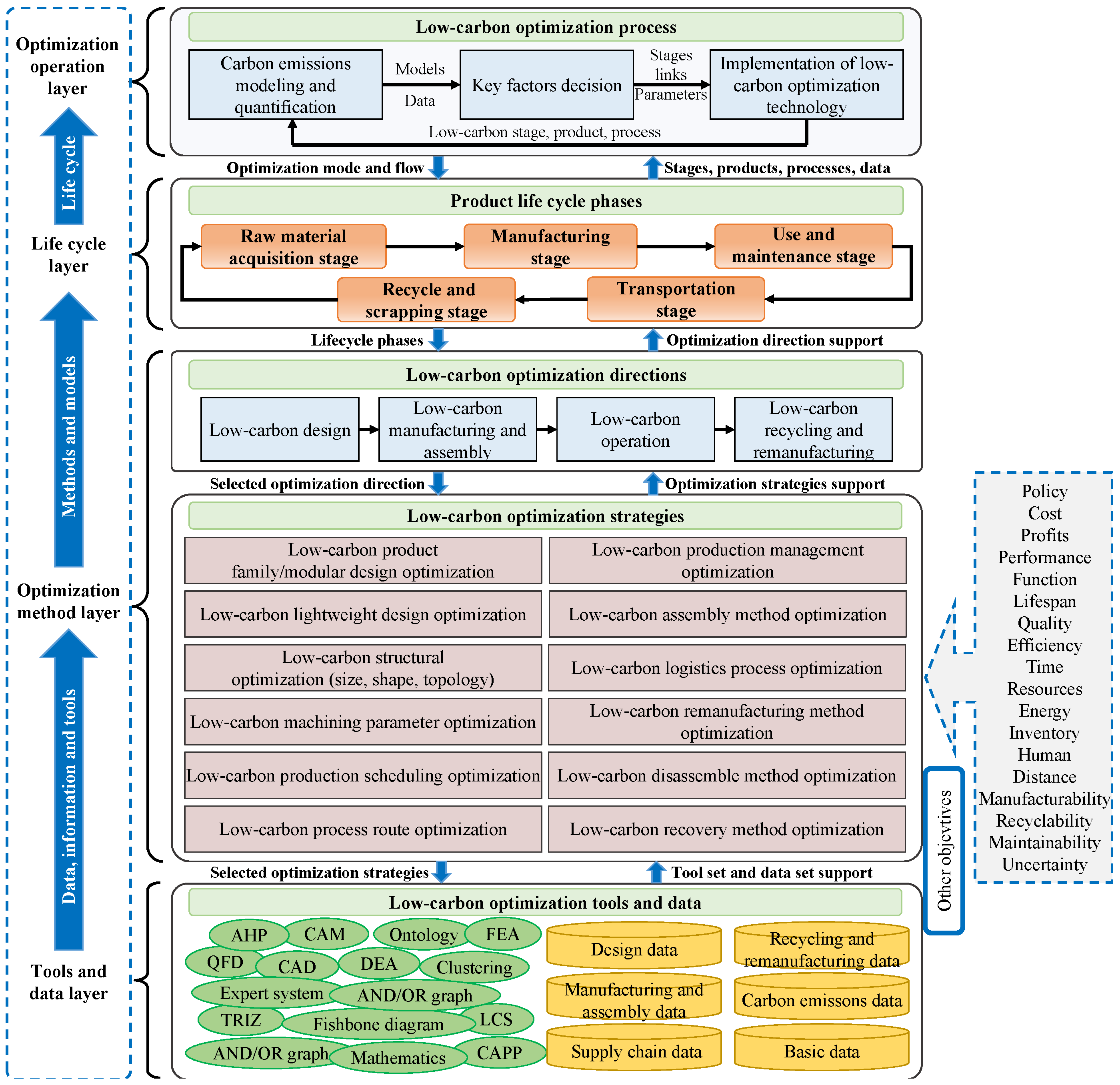
Manufacturing equipment is a capital-intensive, technology-intensive, and knowledge-intensive industry. To reduce the carbon emissions generated in different life-cycle stages or the whole life-cycle process of manufacturing equipment, a four-layer framework of low-carbon optimization processes is established, as shown in
Figure 1. The low-carbon-driven framework for manufacturing equipment has four layers, which are the optimization operation layer, life-cycle layer, optimization method layer, and tools and data layer. These layers provide support for the entire optimization process considering the low-carbon optimization flow, life-cycle stages, optimization methods, and basic data and tools. The four layers are integrated together to form a complex low-carbon optimization process, which is described as follows.
The four layers, which are closely related to each other, comprise a low-carbon-driven optimization framework for manufacturing equipment. From the top down, the first layer is to determine the low-carbon optimization process for manufacturing equipment, which makes the process clearer and more feasible. Then, according to the first layer, carbon emissions are calculated by analyzing energy consumption and material consumption. To make the optimization more efficient and accurate, the key stages and bottlenecks are eventually identified in this layer. The reasonable low-carbon directions and strategies will be determined in the third layer, which is a crucial part in the framework. Generally, more than one direction or strategy will be implemented in the optimization process. At the same time, the fourth layer provides data, information, and methods to support the whole low-carbon optimization process.
As the top layer of the framework, the optimization operation layer shows a general low-carbon optimization flow. It provides a mode or a flow for the low-carbon-driven product life-cycle process optimization for manufacturing equipment for the purpose of energy saving and emission reduction. The flow of low-carbon process optimization includes three main steps, which are (1) carbon emissions modeling and quantification of manufacturing equipment, (2) key factors in the decisions regarding manufacturing equipment, and (3) the implementation of low-carbon optimization technologies. The three steps are organized through the logic of analyzing problems, locating problems, and solving problems. The problems here refer to an optimization problem of carbon emissions for manufacturing equipment. In order to reduce the carbon emissions of products, they are qualified according to a given quantification range. Thus, the carbon emission quantification boundary should first be defined to set which processes, scopes, and objectives will be evaluated. Then, the key factors will be identified and decided upon using quantitative or qualitative methods. Once the key stages, links, or parameters are decided, concrete low-carbon technologies can be implemented, which are more feasible and efficient.
The life-cycle layer contains the life cycle of manufacturing equipment, which includes raw material acquisition, manufacturing, use and maintenance, transportation, and recycle and scrapping. The activities in every stage require the input of material and energy to complete and maintain corresponding functions. With the input and output of various materials, energy, products, and waste in the life cycle of manufacturing equipment, the sources of carbon emissions are numerous and complex. The consumption, conversion, and transmission of energy and materials in different links of life-cycle processes result in the characteristics of multiple sources, variability, and superposition of carbon emissions. Therefore, it is necessary to analyze the energy flow and material flow in the life cycle of manufacturing equipment, so they can provide support for the carbon emissions quantification process.
The low-carbon optimization process is given based on the analysis of the product life cycle. The optimization method layer is the core of the low-carbon-driven product life-cycle process optimization framework. The layer has two parts, namely the low-carbon optimization directions and the low-carbon optimization strategies. They provide low-carbon optimization methods and models for the upper life-cycle layer. The low-carbon optimization directions are divided according to life-cycle stages, which are the low-carbon design, low-carbon manufacturing and assembly, low-carbon operation, and low-carbon recycling and remanufacturing. Low-carbon optimization strategies give the specific measures to take to reduce the carbon emissions generated in different life-cycle stages. The strategies may include, but are not limited to, the methods shown in
Figure 1. With the development of technology, some new emerging concepts and technologies such as new materials/processes/structures, 5G, Digital Twin (DT), and Manufacturing Big Data (MBD) are integrated into the optimization strategies.
The tools and data layer is the foundation for the whole low-carbon optimization process, because the layer provides many optimization tools and data to support the process. Therefore, a lot of database and basic methods can be integrated into the layer to provide data, information, and method support for the optimization process.
3. Four Low-Carbon Optimization Layers
In order to understand the whole framework, the details and technologies involved in the four layers are elaborated on as follows.
3.1. Optimization Operation Layer
Manufacturing equipment is a kind of sophisticated electromechanical equipment composed of mechanical, electrical, hydraulic, control, and other systems, including thousands of components and parts. This means that the low-carbon optimization process of manufacturing equipment is a knowledge-intensive activity. We can implement the optimization process of manufacturing equipment according to the three steps presented, which are described as follows.
- (1)
Define the carbon emissions boundary and quantify carbon emissions in the life cycle of manufacturing equipment.
As reducing carbon emissions is one of the main objectives in the proposed framework, the first step is to define the carbon emissions boundary according to the actual needs of manufacturing equipment. Especially, manufacturing equipment can produce a wide range of goods, and it is often a kind of long-lifetime products. The carbon emissions in the whole life cycle of manufacturing equipment have the characteristics of multi-source, variability and superposition. At the same time, there is complex relationships among life cycle stages, and every stage has multiple links. Each link has different input and output, thus they generate a lot of carbon emissions. Therefore, a machining process or a life cycle stage can be defined as the carbon emissions boundary to analyze and qualify carbon emissions generated within the boundary. Finally, the total carbon emissions can be obtained by evaluating the energy and materials consumed in the boundary based on carbon emissions evaluation tools and methods, such as life cycle assessment and ISO 14040 [
34].
- (2)
Locate the key factors from the carbon emissions boundary of manufacturing equipment.
The second step of optimization process is to locate the key factors that influence carbon emissions over the whole life cycle stages. The key factors could be a stage, a process, a link or even a parameter, and the key factors are the bottleneck to affect carbon emissions. It is a hard task to identify the key factors in the case of integrating material carbon emissions and energy carbon emissions at each stage of manufacturing equipment. However, it is necessary to locate the key factors because the step is very important for the next optimization. By this step, the optimization potentials and emission-reduction effect will be more effective. For the life cycle stages, the generation of indirect carbon emissions is essentially due to the consumption of electrical energy and material. Much more carbon emissions come from raw material preparation, parts machining, equipment operation, transportation and so on. So, the key factors can be identified by analyzing each link of these process. Generally, the key factors can be located by the methods of human experience, experiment, mathematics and numerical simulation. Some studies indicate that the manufacturing stage and use stage cause more carbon emissions than other stages. Therefore, the two stages are paid more attention in previous studies. Obviously, the key stage here could be manufacturing stage or use stage if the carbon emissions boundary is the entire life cycle. Then, based on experiment methods or numerical simulation, the key links, parts or parameters can be obtained. For example, the links of manufacturing stage can be analyzed, such as workpiece, machining process, machining equipment, auxiliary device, etc. Thus, the key parameters and processes will be easier to identify.
- (3)
Implement low-carbon optimization technologies based on the selected key factors.
Based on the located factors, the specific reason leading carbon emissions should be further analyzed and then a corresponding strategy will be carried out, which is the third step in the optimization operation layer. Taking the minimum carbon emissions as one of the main targets, the low-carbon optimization for design, manufacturing, assembly, operation, transportation and recycling is the feasible optimization directions to execute different optimization methods and strategies, while meeting the requirements of function, performance, economy, policy and so on. Recognizing the root reason causing carbon emissions is crucial because the strategies that applied in the optimization are totally different at this step. As we know, energy consumption and material consumption are the main reasons of carbon emissions in the manufacturing system. The major energy consumption is electricity and the material consumption could be part fabrication, cutting fluid, parts preparation, etc. Therefore, the measures to be taken should be according to the cause of carbon emissions. The low-carbon optimization faces many complicated problems such as a collaborative optimization among different objectives, stages, and parameters. How to coordinate the optimization process of each link to make the whole life-cycle stages optimal is a system-level problem. Thus, the low-carbon optimization technologies according to the key factors could save more energy, reduce more consumption, and improve quality and efficiency of manufacturing equipment finally.
3.2. Life-Cycle Layer
The goal of life-cycle layer in the framework is to construct a life-cycle process integrating multi-form flows to support the low-carbon optimization process of manufacturing equipment. Different flows are analyzed in this layer to evaluate carbon emissions and other life-cycle factors. The multi-form flows could be information flow (entropy flow/data flow/knowledge flow, etc.), energy flow, material flow, or carbon emissions flow. By describing and analyzing multi-form flows, the information related with key factors identification, carbon emissions evaluation, and emission-reduction measures can be obtained and provided for the low-carbon optimization process. The low-carbon-driven life-cycle process of manufacturing equipment is an open and uncertain complex system, which generally includes the activities of raw material acquisition, manufacturing, use, maintenance, transportation, recycling, and scrapping. If the raw material acquisition stage is taken as the beginning of the product life-cycle, the final product can be viewed as a process of constant energy and material input and output. Importantly, analyzing and modeling carbon emissions flow is a necessary step, with the goal of carbon emissions reduction. The ease with which it may be possible to construct a flow model of carbon emissions for the whole life cycle or a life-cycle stage will depend on the modelling granularity. From a life-cycle perspective, every life-cycle stage should be estimated and optimized to reduce the overall carbon emissions. However, it is exceptionally hard to collect all data or processes from the cradle to the grave. Thus, an adequate carbon emissions boundary is important for an enterprise. Taking the manufacturing stage as an example, if a workshop is set as the carbon emissions boundary, the quantification of carbon emissions contains different devices, manufacturing cells, and manufacturing equipment, etc. Specifically, if more details are taken into consideration in the boundary, the blanks, parts, tools, fixtures, processing states, and cooling system also have an impact on carbon emissions. The modelling granularity depends on the actual optimization objects.
3.3. Optimization Method Layer
Low-carbon optimization directions and low-carbon optimization strategies form the optimization method layer. The upper low-carbon optimization directions provide feasible strategic directions, which are very important for optimization results. Then, according to the selected directions, many corresponding optimization strategies can be applied to optimization problems.
3.3.1. Low-Carbon Optimization Directions
According to the determined key factors, it is feasible and efficient to carry out targeted low-carbon optimization methods based on the analysis of multi-form flows in the life-cycle layer. Low-carbon design is an effective way to reduce carbon emissions. By applying design methods, such as material selection or structure improvement, the goal of carbon emissions reduction can be realized from the source. Low-carbon manufacturing and assembly means the measures to reduce carbon emissions can be realized by implementing an adjustment of the process parameters, routes, and methods, as well as the optimization of assembly tools, sequences, and methods. Low-carbon operation refers to full control of the service process of manufacturing equipment from the aspect of material consumption and energy consumption, such as mode of transportation, operation management of equipment itself and production management optimization. Low-carbon recycling and remanufacturing means to take the measures of recycling or remanufacturing for devices, parts, waste, etc. The technologies of energy and material recovery, energy matching control, and energy consumption monitoring can be used for optimization.
3.3.2. Low-Carbon Optimization Strategies
According to the low-carbon optimization directions, different optimization strategies are required in order to execute. As shown in
Table 1, the correlation between optimization directions and optimization strategies are listed.
Based on the table, once the optimization directions are decided, the optimization strategies can be easily selected. An idea for implementing low-carbon optimization in stages for different targeted directions is presented here. That is, different life-cycle stages correspond to different low-carbon optimization directions, and different low-carbon optimization directions correspond to different low-carbon optimization strategies. Meanwhile, there is not a one-to-one correspondence between optimization directions and optimization strategies. For example, if the manufacturing stage is positioned to improve, the root cause of carbon emissions should first be analyzed. Incorrect machining parameters, complex parts features, or lower utilization between different devices that lead to too much free time can all potentially become a major reason for carbon emissions. Therefore, on the basis of key factor analysis, low-carbon optimization directions, such as low-carbon design or low-carbon manufacturing, can be selected to improve the situation, then different optimization strategies can be picked out according to the selected low-carbon optimization directions. Thus, the strategy of low-carbon machining parameter optimization could be used to solve the previous problem corresponding to incorrect machining parameters. Low-carbon structural optimization (size, shape, and topology) can be selected to deal with the problem of the features of complex parts. Specially, the strategy can be applied to weight optimization of parts, size optimization for workpieces, tolerance optimization, volume optimization, etc. In addition, lower utilization between different devices could be solved by the strategy of low-carbon production management optimization. The strategy can be adopted to solve production mode optimization (such as mass customization and intelligent manufacturing), production line optimization, etc. So, the bottleneck requires one or more strategies to optimize carbon emissions.
In addition, comprehensive consideration needs to be given to the purpose of optimization according to the other requirements of the equipment products at different stages besides the important indicator of carbon emissions. With this in mind, it is also important to consider economic factors (cost, profit, etc.), time factors (delivery time, processing time, etc.), product performance factors (quality, maximum error, stiffness, stability, etc.), manufacturability, recyclability, maintainability, etc. These factors should also be used as evaluation indicators for low-carbon products to carry out environmental impact assessment, life-cycle cost assessment, product-reliability assessment, product-life assessment, etc. To sum up, the low-carbon optimization of equipment products in their full life cycle must be a multi-objective, multi-strategy, and multi-dimensional complex optimization scheme. A balance of economy, society, and environment should be simultaneously coordinated. Taking the key factors of carbon emissions in the life cycle as the core will be a powerful starting point for the gradual development of a low-carbon optimization process, which is more feasible and efficient.
3.3.3. The Process to Determine the Low-Carbon Optimization Method
There are so many low-carbon optimization directions and strategies in the framework. Because of the situation above, it is necessary to elaborate on how to choose an appropriate one. As shown in
Figure 2, the selection flow of low-carbon optimization methods process is given.
Considering the field of machine tool equipment, if we want to determine which low-carbon optimization method to apply, it takes roughly three steps to achieve that. In the first step, you need to figure out your optimized object. The optimization objective may be a part, machine tool, or even a workshop. Then, in the second step, you should determine the appropriate directions. In the figure, single machine tool (parts, assembly, and machine tools) and multiple machine tools (manufacturing unit, production line, workshop, and factory/enterprise) correspond to four directions respectively. Different colors represent different directions, i.e., blue (Direction 1), orange (Direction 2), yellow (Direction 3), and green (Direction 4). For example, if the objective is a shaft, it will have three directions, namely blue (Direction 1), orange (Direction 2), and green (Direction 3), so as to reduce carbon emissions. This means that, for one part, the optimization could be carried out for the design, manufacture, assembly, and recycling. In the third step, the feasible optimization strategies could be selected. One direction produces variable optimization strategies. In theory, these strategies could all be applied to the optimized objective. However, not all of the strategies are achievable and important for different objectives, because there are still other factors to consider, such as cost, equipment, technical solutions, and so on.
In Direction 1, materials, mass, structures, and features can be optimized in order to conduct low-carbon design. In Direction 2, machining/processing parameter and production scheduling can be used. In Direction 3, remanufacturing, disassembly, and recovery can be used. In addition, one or more directions could be selected for a part. Knowing how to choose an adequate optimization method and tools, and how to apply to the final products and objectives successfully, depends to a great extent on the experts’ knowledge and skills, rules and policies, and enterprises’ own characteristics.
3.4. Tools and Data Layer
The low-carbon optimization process includes many links in the product life cycle, and each link contains many general or specialized optimization tools and data to support the process. The construction of optimization tools and data is an explorative process of continuously practicing, summarizing, and perfecting.
The optimization tools are classified according to the function of tool types. They are life-cycle assessment methods and tools, manufacturing-system simulation and optimization methods and tools, knowledge-modeling methods and tools, big-data and artificial-intelligence methods and tools, and general tools and assessment methods. In addition, there are also many mathematical theories and solution methods in this layer. Each type provides different models, methods, and tools that support the optimization process.
Table 2 lists the partial available optimization tools.
Besides the optimization tools in the layer, the optimization process also generates some data. According to the emerging stage or purpose, the data can be divided into the design data (e.g., product design models, design document, and BOM), manufacturing and assembling data (e.g., process models, process CARDS, tool information, and equipment information), supply chain data (logistics data, supplier data, etc.), basic data (general standards, industry standards, material properties, tolerance and measurement, etc.), carbon emissions data (carbon emission factor, material consumption, energy consumption, etc.).
Because the data have the complex characteristics of a large amount, diversity, and dynamics, there are difficulties in data collection and management in the low-carbon optimization process. Based on the analysis of the data characteristics, the tools and data layer does not only provide support for data and tools, but it also has a data processing capacity, including knowledge reasoning.
In conclusion, the goal of low-carbon optimization for manufacturing equipment is to obtain the product and life cycle that have lower carbon emissions through targeted optimization methods and strategies. In addition, other indicators, such as economy, function, and performance, should be ensured to achieve a green manufacturing mode in the manufacturing industry.
5. Conclusions
To support a low-carbon optimization process, this paper introduces a low-carbon optimization framework for manufacturing equipment. The framework includes four layers, which are the optimization operation layer, life-cycle layer, optimization method layer, and tools and data layer. In the optimization operation layer, an available low-carbon optimization process is proposed. The life-cycle layer shows that it is a necessary to analyze and model a carbon emissions flow for carbon emissions reduction because the sources of carbon emissions are numerous and complex. More importantly, the low-carbon optimization directions, low-carbon optimization strategies, and their corresponding relationship are integrated in the framework. According to the selected low-carbon directions, several feasible low-carbon optimization strategies could be selected to solve an optimization problem. The tools and data layer can provide data, information, and methods for a low-carbon optimization process. Using the proposed framework and methodology, the effectiveness is verified by applying a honing machine. In this case study, the carbon emissions can be reduced without sacrificing the structure performance. Moreover, it is concluded that the overall effect of carbon emissions produced in different life-cycle stages should be considered when a low-carbon measure will be taken.
Low-carbon optimization framework is important for reducing the energy and carbon emissions of manufacturing equipment. Because of the complexity of low-carbon optimization for manufacturing equipment, the lower column and a simple structure scheme are taken as the example to illustrate the framework. In future work, more complex components, multiple life-cycle stages, and more low-carbon optimization schemes will be explored. In addition, the low-carbon optimization directions and strategies will be extended in the framework, such as additive manufacturing. Moreover, this is not the only strategy to reduce carbon emissions in practical applications, instead there are different strategies, such as the environmental impact, economy, and time taken, that should be considered for manufacturing equipment.


