Article

Free Vibrations of Sustainable Laminated Veneer Lumber Slabs

by
Małgorzata Abramowicz
1,
Marcin Chybiński
2,
Łukasz Polus
2,* and
Tomasz Wróblewski
1
1
Faculty of Civil and Environmental Engineering, West Pomeranian University of Technology in Szczecin, Al. Piastów 17, 70-310 Szczecin, Poland
2
Institute of Building Engineering, Faculty of Civil and Transport Engineering, Poznan University of Technology, Piotrowo 5 Street, 60-965 Poznan, Poland
*
Author to whom correspondence should be addressed.
Sustainability 2024, 16(1), 166; https://doi.org/10.3390/su16010166
Submission received: 7 November 2023 / Revised: 18 December 2023 / Accepted: 21 December 2023 / Published: 23 December 2023
(This article belongs to the Section Energy Sustainability)

Abstract

:
In this paper, the results of dynamic laboratory tests of four laminated veneer lumber (LVL) slabs of different thicknesses, widths, and types were presented. In three of the tested slabs, LVL with all veneers glued lengthwise was used (LVL R). In one LVL slab, a fifth of the veneers were glued crosswise (LVL X). Laminated veneer lumber slabs are engineering wood products with several important performance characteristics, making them a sustainable and preferred solution in civil engineering. To ensure the safe operation of a building with LVL structural elements, it is important to know their dynamic properties. The basic dynamic characteristics of the slabs obtained from experimental tests made it possible to validate the numerical models of the slabs. The slab models were developed in the Abaqus program using the finite element method. The elastic and shear moduli of laminated veneer lumber used in the four slabs were identified through an optimization process in which the error between the analyzed frequencies from the laboratory tests and the numerical analyses was minimized. In the case of slabs that possess the same thickness and are composed of different LVL types, the elastic modulus of LVL R in the longitudinal direction was 1.16 times higher than the elastic modulus of LVL X in the same direction. However, the elastic moduli of LVL R in tangential and radial directions were lower than the elastic moduli of LVL X in the same directions. The above was the result of the fact that the 45 mm LVL X slab had 3 out of 15 veneers glued crosswise. In the case of slabs possessing different thicknesses but the same width and type, the elastic modulus of the thicker panel was 1.13 times higher than that of the thinner panel. After validating the models, the numerical analyses yielded results consistent with the experimental results. The numerical models of the LVL slabs will be used to develop numerical models of composite floors with LVL panels in future research. Such models will allow for the analysis of floor dynamic characteristics and user-generated vibrations, which is required when verifying the serviceability limit state.

1. Introduction

1.1. LVL as a Sustainable Material

Improvements in the construction sector and the use of environmentally friendly solutions are vitally important to reducing greenhouse gas emissions. One of the possibilities is to replace steel and concrete with timber [1]. Timber buildings have a lower embodied carbon footprint compared to steel and concrete buildings. Not only does the use of timber buildings reduce CO2 emissions, but it also makes it possible to store carbon [2]. Timber is natural, eco-friendly, recyclable, and renewable. Therefore, it is a sustainable building material. Timber from end-of-service-life buildings can be recycled and used for producing heat or other construction materials. The popularization of timber buildings should go hand in hand with reforestation for it to have a real positive impact on the environment. The popularity of timber as a building material is increasing because of engineering wood products such as laminated veneer lumber (LVL), cross-laminated timber (CLT), and glue-laminated timber (glulam). LVL is a structural composite lumber consisting of veneers laminated together by means of an adhesive [3]. In Poland, two types of LVL are manufactured. In the first type, all veneers are glued lengthwise. In the second type, around a fifth of the veneers are glued crosswise [4]. The quality of LVL and the presence of defects is controlled. Defects are evenly distributed throughout an LVL slab to reduce the variability of its mechanical properties [5]. LVL exhibits increased dimensional stability and greater durability than conventional sawn lumber. LVL elements are obtained from trees of relatively small diameters using the rotary peeling method thanks to which wood resources are used efficiently. The size of the LVL panels is not limited by the original wood size [6]. LVL is produced in different shapes, which can be adapted to its applications [7]. The high strength-to-weight ratio, the aesthetic aspect, the possibility of prefabrication with other structural elements, and the light weight of LVL all enhance its competitiveness [8]. One of the key advantages of using LVL in civil engineering is the environmental benefits that this brings [9]. Wood-based materials such as LVL are about 50% carbon [10]. This carbon is removed from the atmosphere by trees, which sequester CO2 during their growth process, thus mitigating the climate change caused by the greenhouse effect [11]. The strength parameters and the insulating properties of LVL make it possible to build more energy-efficient and lighter structures than the equivalent masonry or concrete structures [12]. Each part of the wood can be used efficiently to produce LVL [13]. Waste wood from LVL production can be used for wood-fiber insulation, heartwood (for transport pallets), and bark or residual materials (for energy production) [14]. Not only does the use of LVL have environmental benefits, but it can also provide corrosion-resistant solutions. LVL can be used in buildings where structural elements are exposed to the caustic effects of chemical vapours, such as swimming pools or fertilizer sheds [15]. Massive portal frames made of LVL may have higher fire resistance than unprotected steel frames [15]. Nowadays, it is possible to use LVL for the construction of sports halls, warehouses, small-scale manufactories, animal housing, or aircraft hangars. LVL structural elements can be used in prefabricated and kitset solutions. These solutions reduce build time and minimize the risk of construction errors. Due to the lightness of LVL, it is possible to use construction cranes of lower load capacity and smaller foundations in buildings. The use of LVL, instead of steel or concrete structural elements, can reduce emissions. Winchester and Reilly evaluated the impact of replacing carbon-intensive construction materials (e.g., steel and cement) with engineered wood products on CO2 emissions from fossil energy in the USA [16]. It was found that the CO2 intensity of lumber production is under 50% that of steel and under 25% that of cement. Upton et al. demonstrated that net greenhouse gas emissions associated with wood-based houses were 20–50% lower than emissions associated with thermally comparable steel- or concrete-based houses [17]. Tellnes et al. compared the wood structure of a six-story housing complex constructed in Gothenburg, Sweden with an equivalent steel-and-concrete structure [18]. The wood structure was made of laminated veneer lumber floors and glue-laminated beams and columns. The equivalent steel-and-concrete structures consisted of steel beams and columns, as well as concrete floors. The results indicated that the steel-and-concrete solution had about 35% higher greenhouse gas emissions than the wood solution. Lu et al. conducted a comparative life cycle assessment of LVL and steel-and-concrete beams [19]. The LVL beam from thinned logs had the lowest potential impact for global warming. The embedded energy of LVL was significantly lower than that of concrete. However, because of the significant energy requirements for wood drying, the embedded energy of LVL was marginally lower than that of steel. Beams made of LVL can be effectively strengthened with ultra-high modulus carbon-fibre-reinforced polymer, aramid-fibre-reinforced polymer, and glass-fibre-reinforced polymer sheets, which was demonstrated by Bakalarz and Kossakowski [20]. LVL is typically used where high strength is needed, e.g., in roof diaphragms and overhangs, floor framing members, lintels, building walls and I-joist flanges, headers above doorways, and garage doors. LVL can also be used in steel–timber [21,22], aluminum–timber [23,24], timber–timber [25,26], and timber–concrete composite structures [27,28,29].

1.2. Dynamic Tests of LVL Slabs

The use of LVL is gaining popularity, especially in the construction of tall buildings made of timber [30], raising an urgent need to explore the dynamic properties of this engineering wood product. On the one hand, the light weight of LVL is an advantage. On the other, it is also a serviceability drawback, which may cause a poor performance of timber floors under dynamic loadings. The serviceability criterion is crucial in designing timber structures, and it becomes increasingly more relevant due to the use of high-strength engineering wood products and longer spans [31]. For this reason, dynamic tests are often used to investigate natural frequencies, mode shapes, and damping ratios of structures with timber elements [32,33,34,35,36]. Bridges are always subjected to dynamic loads, and it is important to pay attention to their modal properties [37,38]. Ceilings in residential and public buildings are exposed to vibrations generated by people. Many standards and publications provide guidelines for the minimum value of the fundamental natural frequency for ceilings. This frequency should be high enough to avoid resonance caused by dynamic interactions generated by the ceiling users (rhythmic steps, sports, dancing activity, etc.). The national annex to BS EN 1991–1–1:2002 states that in the case of vertical vibrations, the natural frequencies of the ceiling should be greater than 8.4 Hz. In the case of horizontal vibrations, it should be greater than 4 Hz [39]. Eurocode 5 differentiates between floors with a low fundamental frequency ≤ 8 Hz, for which a special investigation should be conducted, and floors with a high fundamental frequency > 8 Hz, for which the following requirements must be met [40]:
w F a       [ m m k N ]
ν b f 1 · ζ 1       [ m N s 2 ]
where w is the maximum instantaneous vertical deflection caused by a vertical concentrated static force F applied at any point on the floor, considering load distribution; ν is the unit impulse velocity response, i.e., the maximum initial value of the vertical floor vibration velocity (in m/s) caused by an ideal unit impulse (1 Ns) applied at the point of the floor, providing the maximum response. In addition, ζ is the modal damping ratio and f1 is the fundamental frequency [Hz] of the rectangular floor simply supported along all four edges, which can be calculated as:
f 1 = π 2 l 2 E I l m
where m is the mass per unit area [kg/m2], l is the floor span [m], and (EI)l is the equivalent plate bending stiffness of the floor about an axis perpendicular to the beam direction [(Nm2)/m].
The recommended range of and relationship between a and b is provided in Figure 1. According to EKS 10: BFS 2015:6, the following values may be used: a = 1.5 mm/kN, b = 100 m/(Ns2) [41,42].
In industrial buildings, machines generate vibrations, and they require a stable floor of known dynamic properties [43]. Few comprehensive investigations have addressed the dynamic properties of LVL in the literature. Huang et al. conducted two groups of dynamic tests on LVL slabs [44]. In the first group, the LVL slab was suspended; in the second group, it was placed on a sponge. The mode shape and frequency values from the two groups of tests were consistent. The elastic and shear moduli of the LVL panel placed on a sponge from the transient excitation method were 3.99% and 3.08% higher, respectively, than the elastic and shear moduli of the suspended LVL panel from the modal test method. Huang et al. calculated the elastic modulus based on the bending frequency and Equation (4) [44,45,46]:
E = 0.9462 ( ρ f I 2 l 4 ) / h 2
where E is the elastic modulus [Pa], ρ is the average density [kg/m3], fI is the first-order bending frequency [Hz], l is the length [m], and h is the thickness [m] of the specimen.
The modal properties determined in laboratory tests can be used for updating numerical models and for identifying the elastic properties of timber and engineering wood products [47,48,49].
The use of LVL panels in building structures requires a precise determination of their stiffness. An appropriate structural system stiffness is necessary to meet the serviceability limit state requirements for both static and dynamic loads. The stiffness of a structural system is a function of the longitudinal modulus of elasticity. It can be determined based on the knowledge of the basic dynamic characteristics, i.e., the frequency and mode of natural vibrations. These characteristics can be determined using experimental modal analysis techniques and force impulse. In this study, the basic dynamic characteristics of the LVL panels were determined, which allowed for the development of reliable numerical models. The modes of natural vibrations and frequency values obtained from the laboratory tests and numerical analyses were compared. The elastic and shear moduli of LVL were identified through an optimization process in which the error between the frequency values from the laboratory tests and the frequency values from the numerical analyses was minimized. To compare the mode shapes of vibration from the laboratory tests and numerical analyses, the modal assurance criterion (MAC) was used [50,51,52,53,54]:
M A C = Q A T Q B 2 Q A T Q A Q B T Q B
where QA and QB were the mode shape vectors that were being compared.
Thanks to the numerical models of the LVL panels developed in this study, numerical models of composite floors with LVL panels will be developed in future research.

2. Materials and Methods

2.1. The LVL Panels

Four LVL panels of different thicknesses, widths, and types were analyzed. Based on their dimensions, they were designated as P_45_300, P_45_370X, P_75_300, and P_75_370 (Table 1). In the P_45_370X panel, LVL X was used, with 3 of 15 veneers glued crosswise. In the remaining panels, LVL R was used, with all veneers glued lengthwise. The LVL used in this study was fabricated from veneers made of Scots pine and Norway spruce [4].

2.2. The Experimental Tests of the LVL Panels

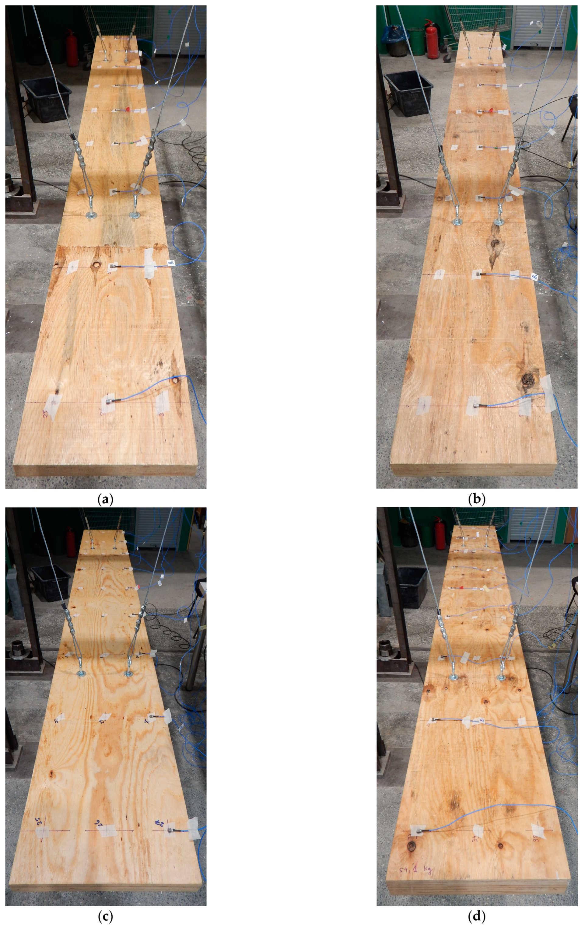
The LVL panels were tested on a steel stand made from two cantilever frames braced with angle sections. The dynamic characteristics of the LVL panels with free ends, suspended with 4 mm steel cables, were investigated (Figure 2). The assumption was that the panel would be tested as a free element, i.e., without supports at the edges. The implementation of such boundary conditions was possible both during the experimental tests and the numerical analyses. During the tests, the tested elements were suspended using flexible cables. The suspension points were selected so that they corresponded with the theoretical nodal points of the first flexural vibration mode of the panel. This is a standard and verified procedure used by dozens of researchers around the world. The stand was used successfully in previous studies on the dynamic characteristics of concrete slabs, steel girders, and steel–concrete composite beams [55,56]. The stand deformability and its effect on the results were considered to be negligible for a free–free scheme [57]. The same boundary conditions were implemented in the numerical model. Most programs, including Abaqus, have no difficulty in solving the eigenproblem for an unsupported structure. There is no need to model suspension cables in a numerical model, which was proven, among others, in the doctoral dissertation [56].
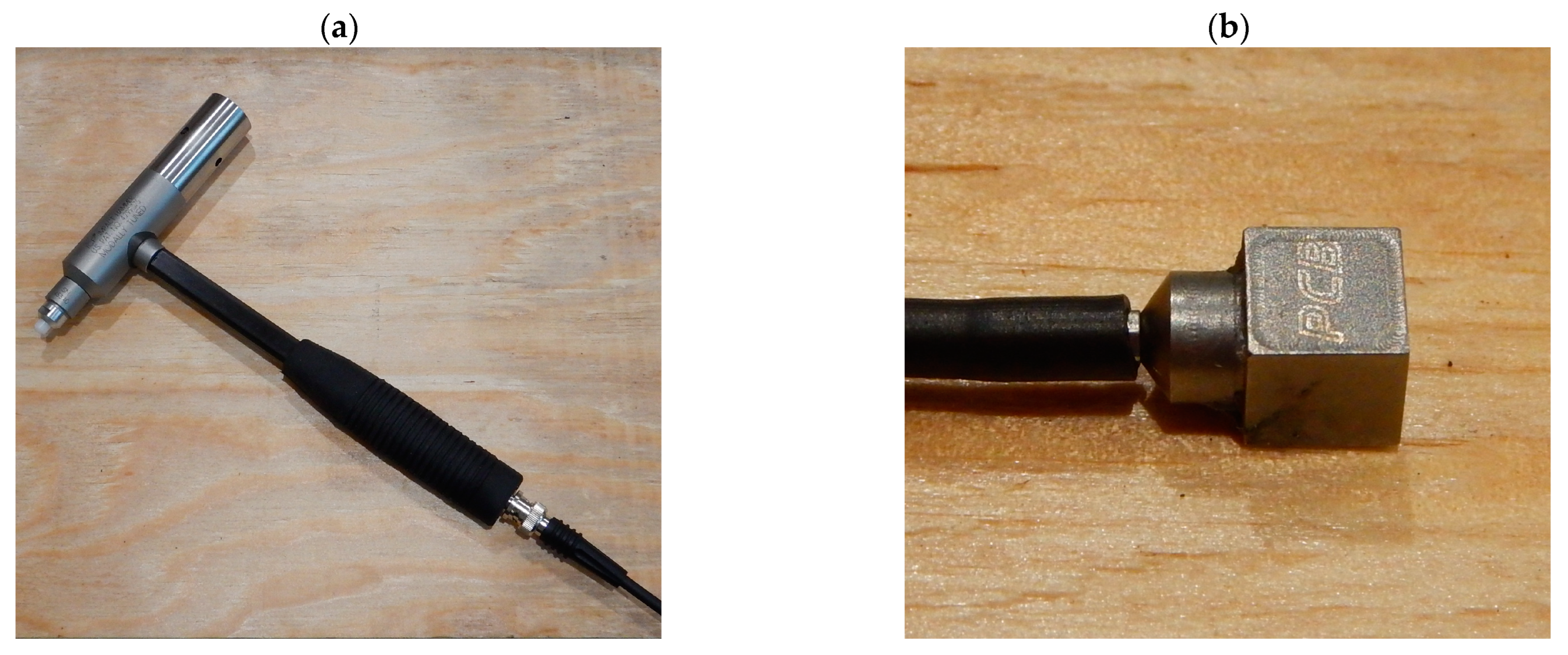
During the tests, impulse excitation was applied using a modal hammer to excite panels into vibration (Figure 3a). The fundamental dynamic characteristics of the LVL panels, i.e., frequency of natural vibration, damping, and frequency response function, were determined. High-frequency results were expected. Therefore, the vibration acceleration was measured, and it was considered to be the response of the panel. Nine PCB 356A01 triaxial accelerometers (PCB Piezotronics, Depew, NY, USA) were attached to the LVL panel using special wax provided by the sensor manufacturer (Figure 3b and Figure 4). Impulses were investigated with excitation generated at four points on the panel, marked in Figure 5 and Figure 6 as: 28 − z vertical impact in the middle of the panel, 30 − z vertical impact on the edge of the panel, 29 + x horizontal impact on the face of the panel, and 30 + y horizontal impact on the edge of the panel. The various excitation points were used to obtain different vibration modes of the panel. Point 28 − z was used to obtain the vertical flexural mode. Point 30 − z was applied to investigate the vertical flexural and torsional modes. Point 30 + y was applied to investigate the horizontal flexural modes. Point 29 + x was used to obtain the axial mode of vibration. A mesh of 27 evenly distributed measurement points was used. The tests were conducted in stages due to the number of points. In one stage, nine sensors measured acceleration at different points placed on the same line. The impulse excitation was generated using a 320 g Modally Tuned, ICP, 086D05 impact hammer (PCB Piezotronics, Depew, NY, USA) with a medium–hard white plastic insert (084B04) tip. For each excitation point, the panels were hit five times. The mesh of the measurement points is presented in Figure 5 and Figure 6. The acceleration responses were recorded using the LMS SCADAS III data-acquisition system (Siemens, Plano, TX, USA). The LMS SCADAS III analyzer was connected to the workstation equipped with a computer-aided system, and the LMS Test Lab package was used to record the signals. The Impact Testing module of the LMS Test Lab package (Siemens, Plano, TX, USA) was used for the impulse tests.

2.3. The Numerical Models of the LVL Panels

The numerical models of the LVL panels with free ends were developed in the Abaqus program. The analyses were conducted assuming the elastic behaviour of the panels. Each LVL panel was modeled using C3D8I solid first-order elements. C3D8I elements are more effective than C3D8R elements. They make it possible to use a smaller number of finite elements per slab thickness compared to C3D8R elements [58,59]. Their standard shape functions were supplemented with so-called bubble functions to eliminate shear locking. The maximum mesh size was limited to 15 mm (Figure 7).
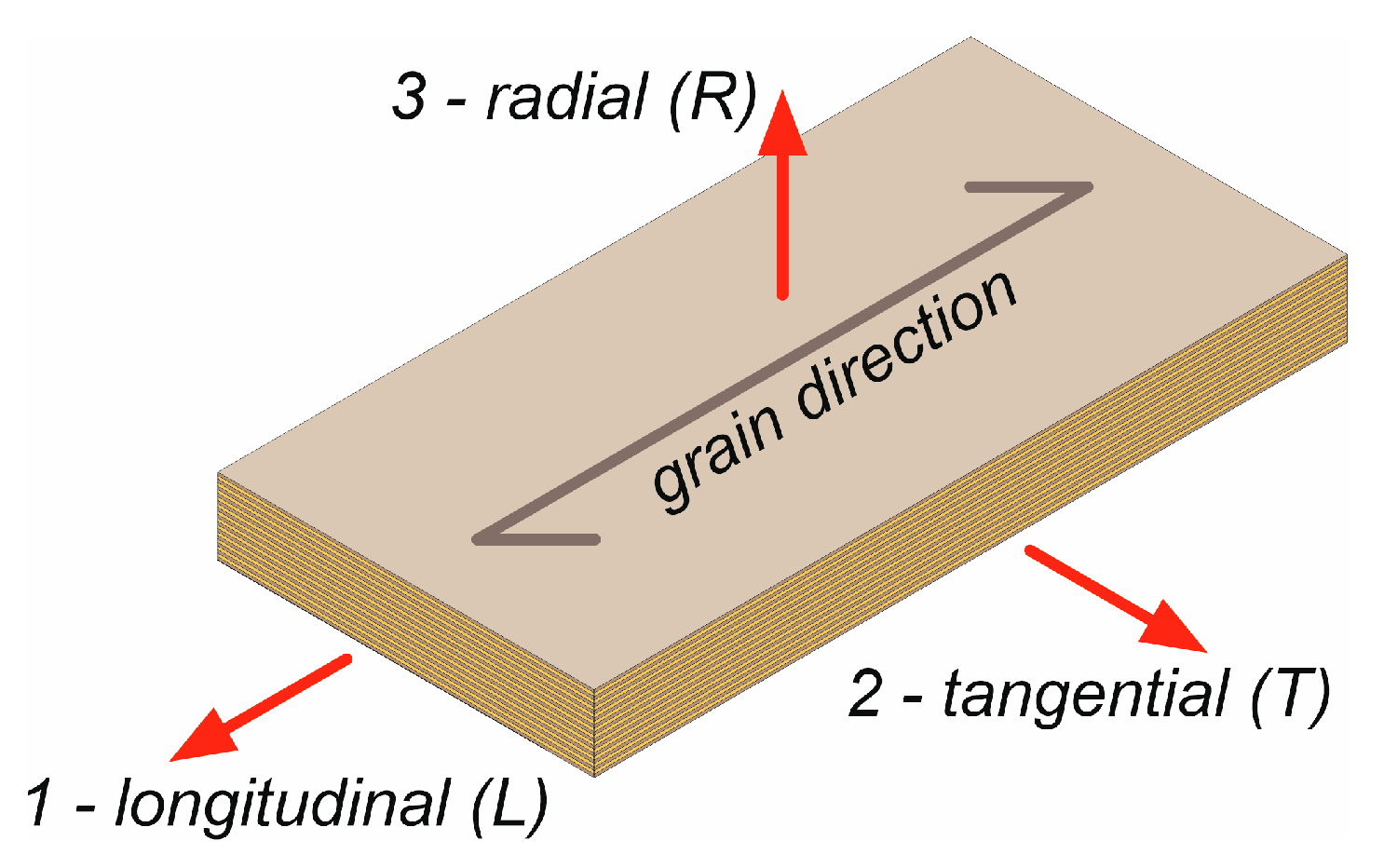
The LVL was modeled as an orthotropic material, considering the material parameters in three directions (Figure 8).
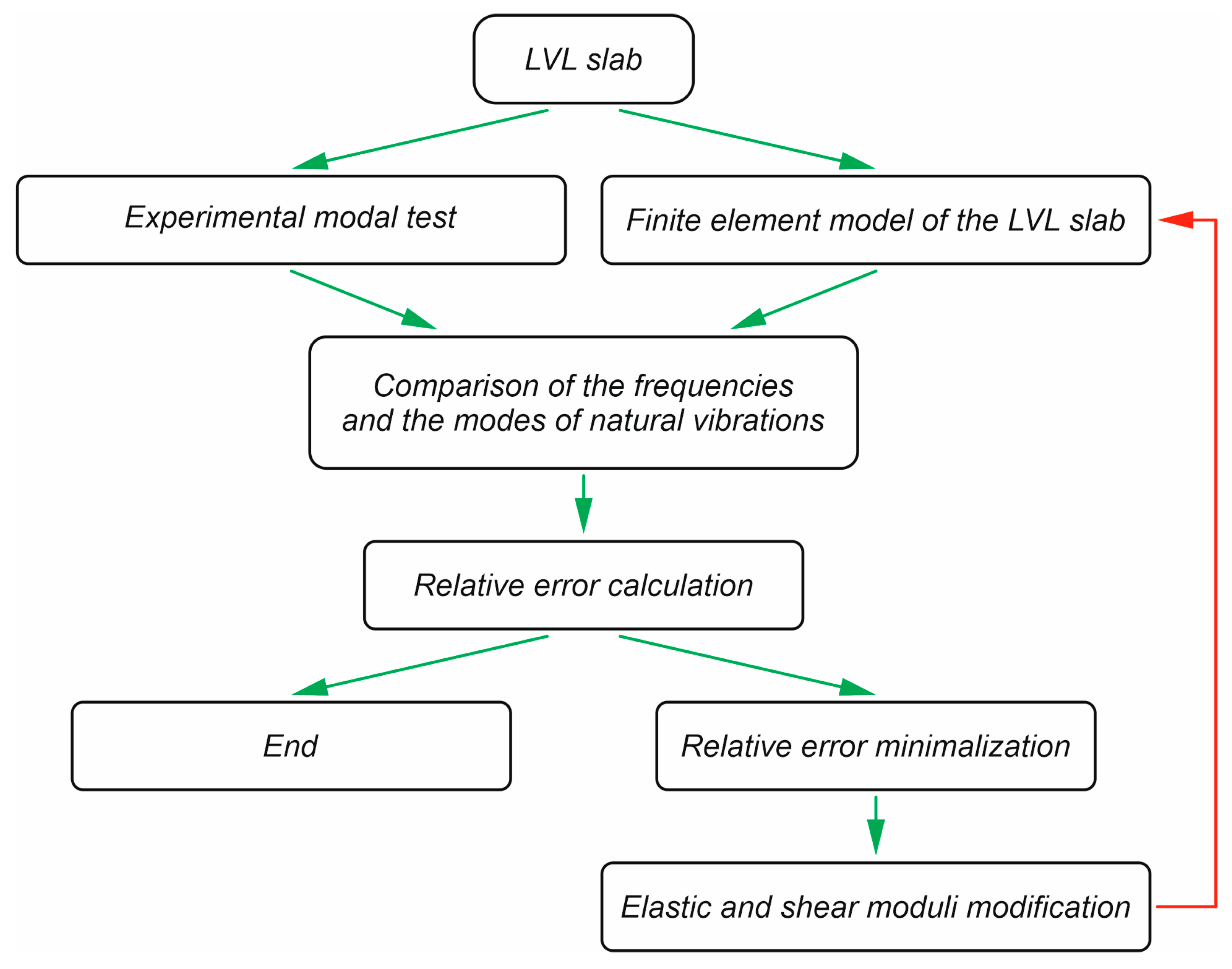
The mechanical properties of the LVL in tangential and radial directions were assumed to be identical. The same approach was used in papers [8,60] based on the test results presented in [61]. This approach was also used for glued laminated timber and solid beams in papers [62,63]. The LVL laboratory tests presented by van Beerschoten [64] demonstrated that in LVL, with all veneers glued lengthwise, tangential stiffness was only slightly higher than radial stiffness. The Poisson’s ratios were adopted from the previous works [8,60]. Due to uncertainties pertaining to the mechanical properties of LVL, the elastic and shear moduli were considered as variables during the validation process. Furthermore, the moduli were identified individually for each panel because they depended on the LVL type (X or R) and on the panel thickness, which was demonstrated by van Beerschoten [64]. Due to the fact that the first axial mode strongly depends on the modulus of elasticity in the longitudinal direction, the value of this modulus was predicted first. Next, the remaining moduli were identified through an optimization process in which the error between the measured and the predicted frequencies was minimized. The values of the moduli were assumed to minimize the relative error:
Δ s u m = i = 1 12 f e x p f c o m f e x p
where fexp and fcom are the natural frequencies obtained from the laboratory tests and from the numerical analyses, respectively.
All 12 natural frequencies obtained from the laboratory tests were used in the identification process to find as accurate material parameters as possible. A schematic diagram of the research method used in this study is presented in Figure 9.

3. Results

Table 2 contains elastic and shear moduli identified through an optimization process in which the error between the measured and the predicted frequencies was minimized. The values presented in Table 2 are: E—longitudinal modulus of elasticity, v—Poisson ratio, G—transverse modulus of elasticity. The designations 1, 2, and 3 correspond to the three main material axes. Direction 1 means the direction along the LVL panel (longitudinal), Direction 2 (tangential) means the direction across the panel, and Direction 3 is perpendicular to the panel plane (radial) formed by Axes 1 and 2. In the case of an orthotropic material, the material properties are different in each direction. In this study, an assumption was made about the isotropic plane in Directions 2 and 3, which results in E2 = E3, v12 = v13, and G12 = G13.
In the case of the LVL type, the elastic modulus of LVL R in the longitudinal direction was higher than the elastic modulus of LVL X in the same direction. For example, the elastic modulus of the P_45_300 panel was 1.16 times higher in the longitudinal direction than in the P_45_370X panel. However, the elastic moduli of LVL R in tangential and radial directions were lower than the elastic moduli of LVL X in the same directions. The above resulted from the fact that P_45_370X was made of LVL X with 3 out of 15 veneers glued crosswise. In the case of panel thickness, the elastic moduli of the thicker panels (P_75_300 and P_75_370) were higher than those of the thinner panels (P_45_300). For example, the elastic modulus of the P_75_300 panel was 1.13 times higher in the longitudinal direction than in the P_45_300 panel. The impact of the panel type and thickness on the elastic moduli was also observed by van Beerschoten [64], who tested 45 mm and 63 mm LVL panels as well as two types of LVL, i.e., LVL with all veneers glued lengthwise and cross-banded LVL. The impact of the LVL type and thickness on the elastic moduli was also considered in manufacturer brochures [65]. For example, the elastic modulus in the longitudinal direction of STEICO LVL R is 1.32 times higher than that of STEICO LVL X (for the thickness t ≥ 27 mm). The elastic modulus in the longitudinal direction of STEICO LVL X (t ≥ 27 mm) is 1.06 times higher than that of STEICO LVL X (t ≤ 24 mm). Small differences between the elastic and shear moduli of the P_75_300 and P_75_370 LVL panels were observed. The panels differed only in slab width, so these small differences were the result of material variability.
The elastic moduli E in the longitudinal direction of the analyzed LVL panels from the optimization process (in which the error between the measured and the predicted frequencies was minimized) were compared with the values calculated using Equation (4) and good convergence was obtained (Table 3).
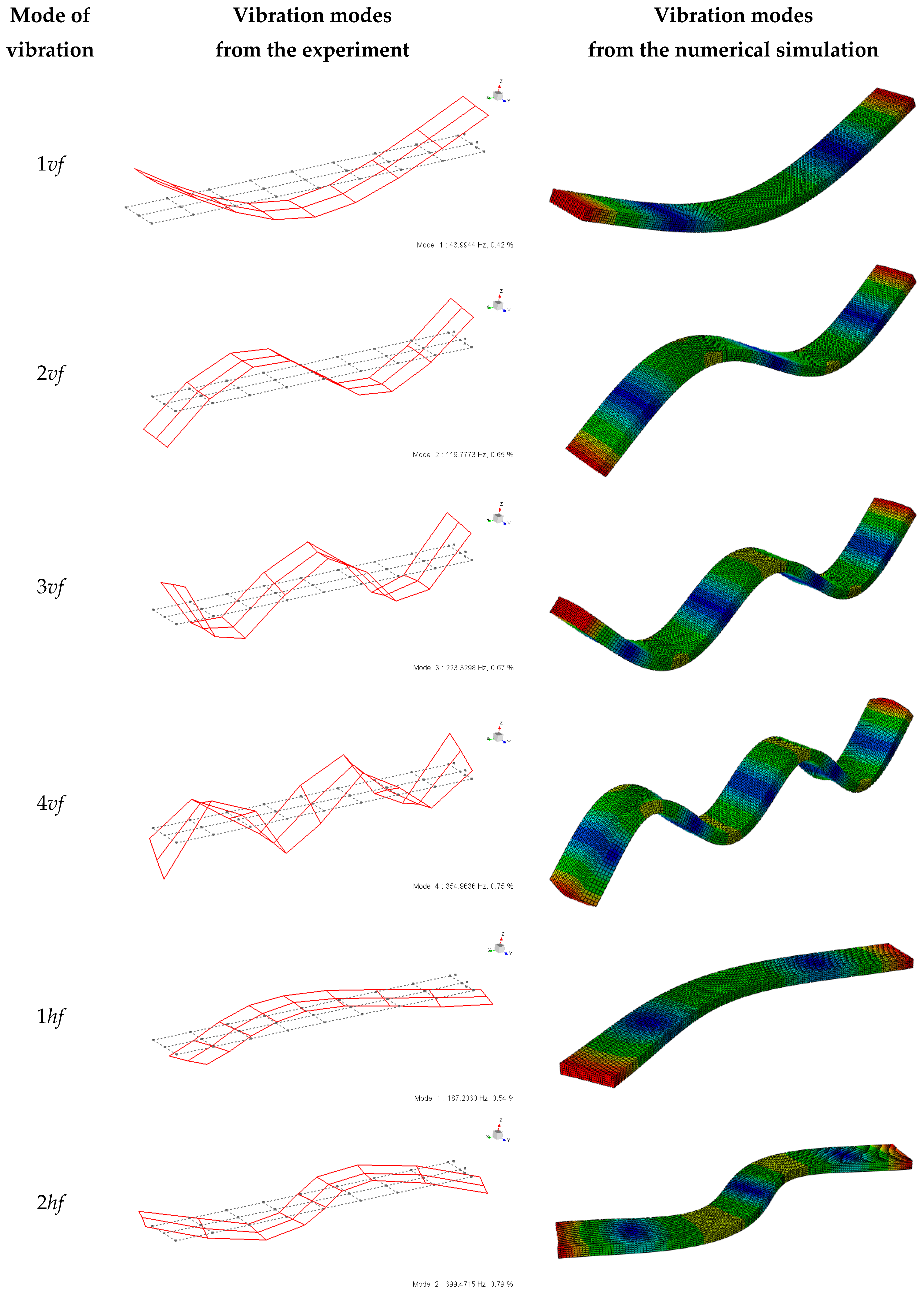
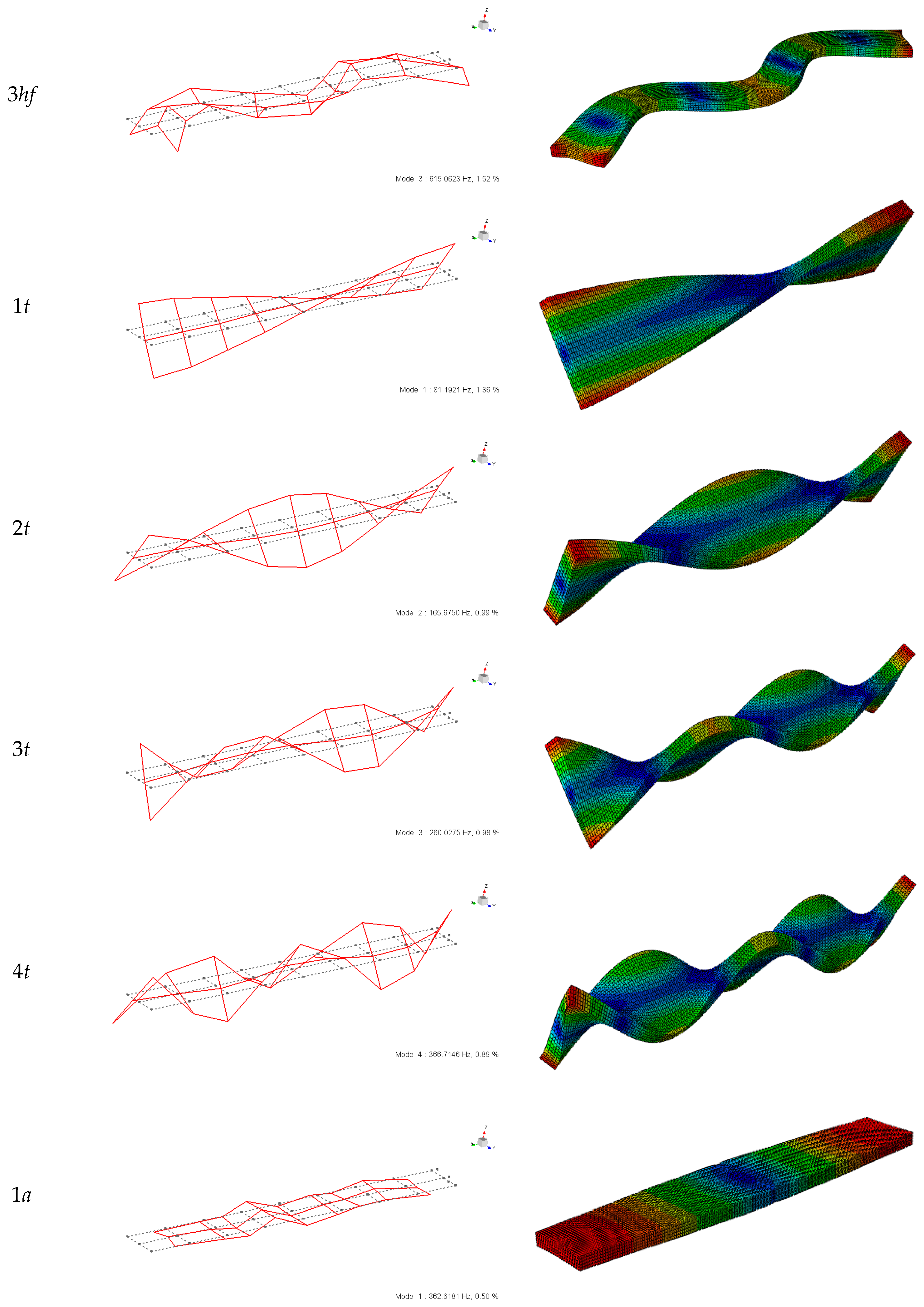
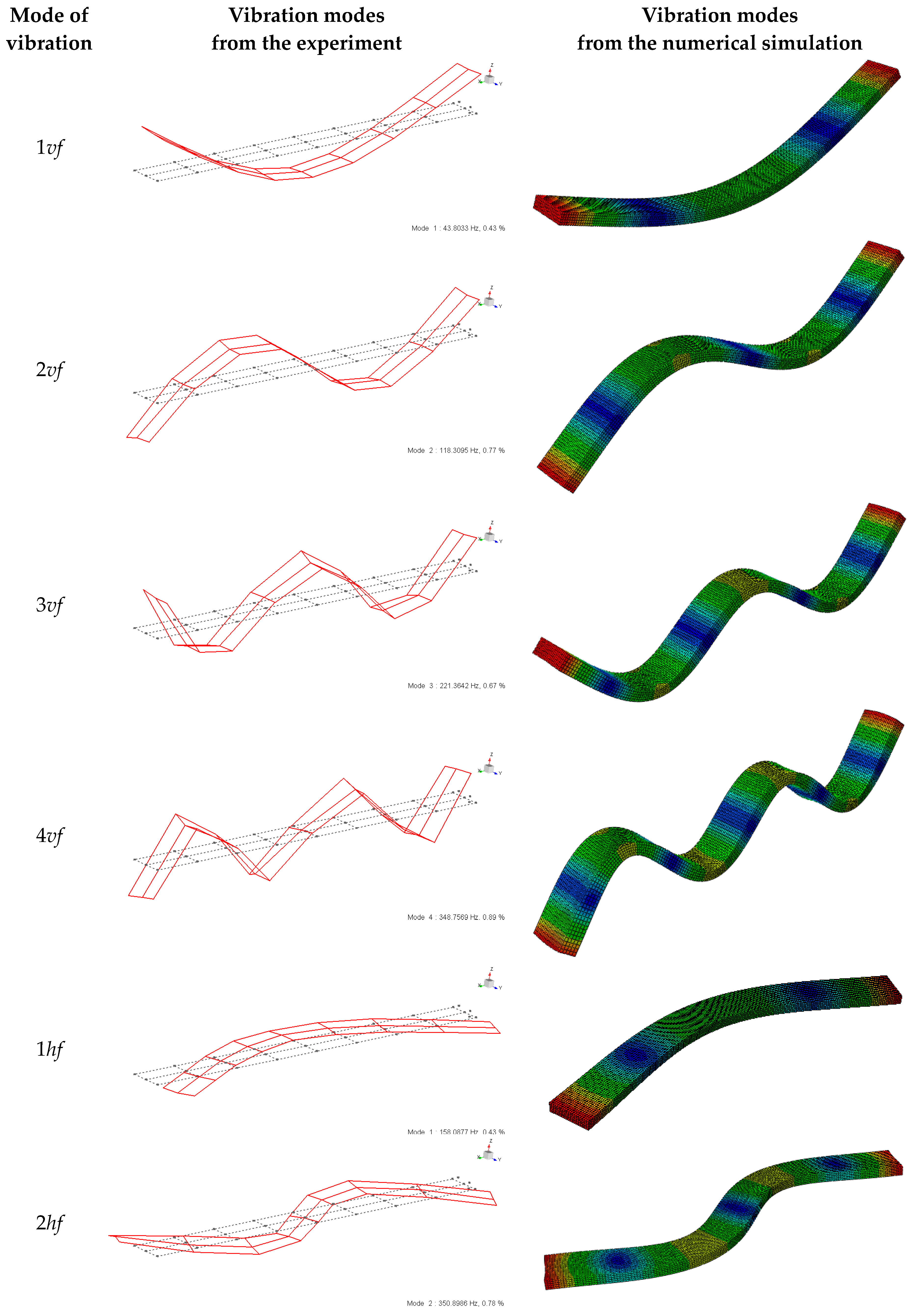
The experimental natural frequencies and the results of the numerical analyses are summarized in Table 4. The symbols used in Table 4 and Figure 10, Figure 11, Figure 12 and Figure 13 are the abbreviations of vibration modes. The following types of natural vibrations were analysed: vf—vertical flexural, hf—horizontal flexural, t—torsional, a—axial. The vibration modes of the P_75_370 LVL and P_75_300 LVL panels predicted in the experiment and in the finite element analysis are presented in Figure 10 and Figure 11. The small values of the relative error indicate good agreement between the results of the numerical analyses and the laboratory tests. The modes from the numerical analyses were consistent with the experimental modes. To limit the number of figures, the modes from the numerical analyses of the P_45_370X LVL and P_45_300 LVL panels were not included in this paper. However, they were also consistent with the experimental modes.
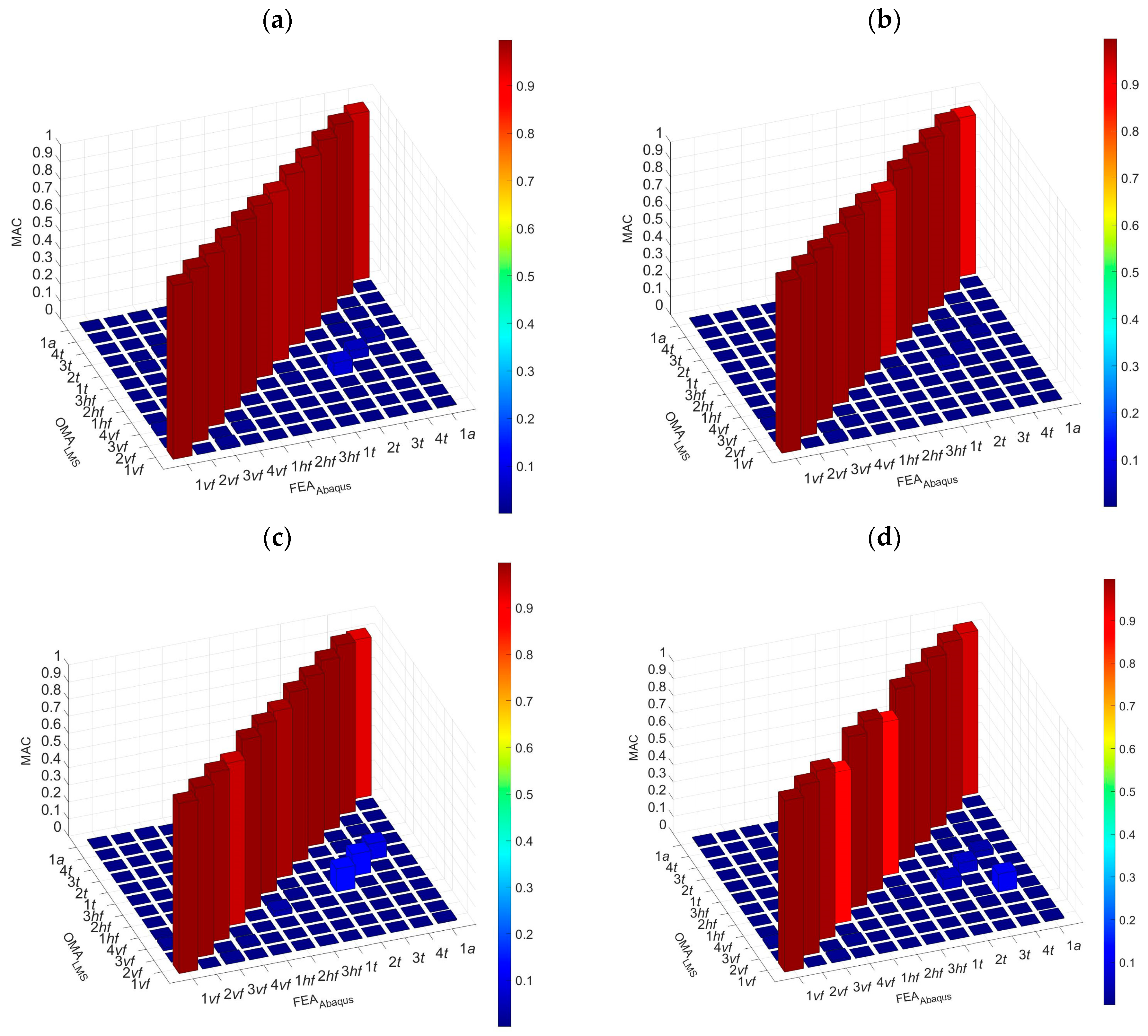
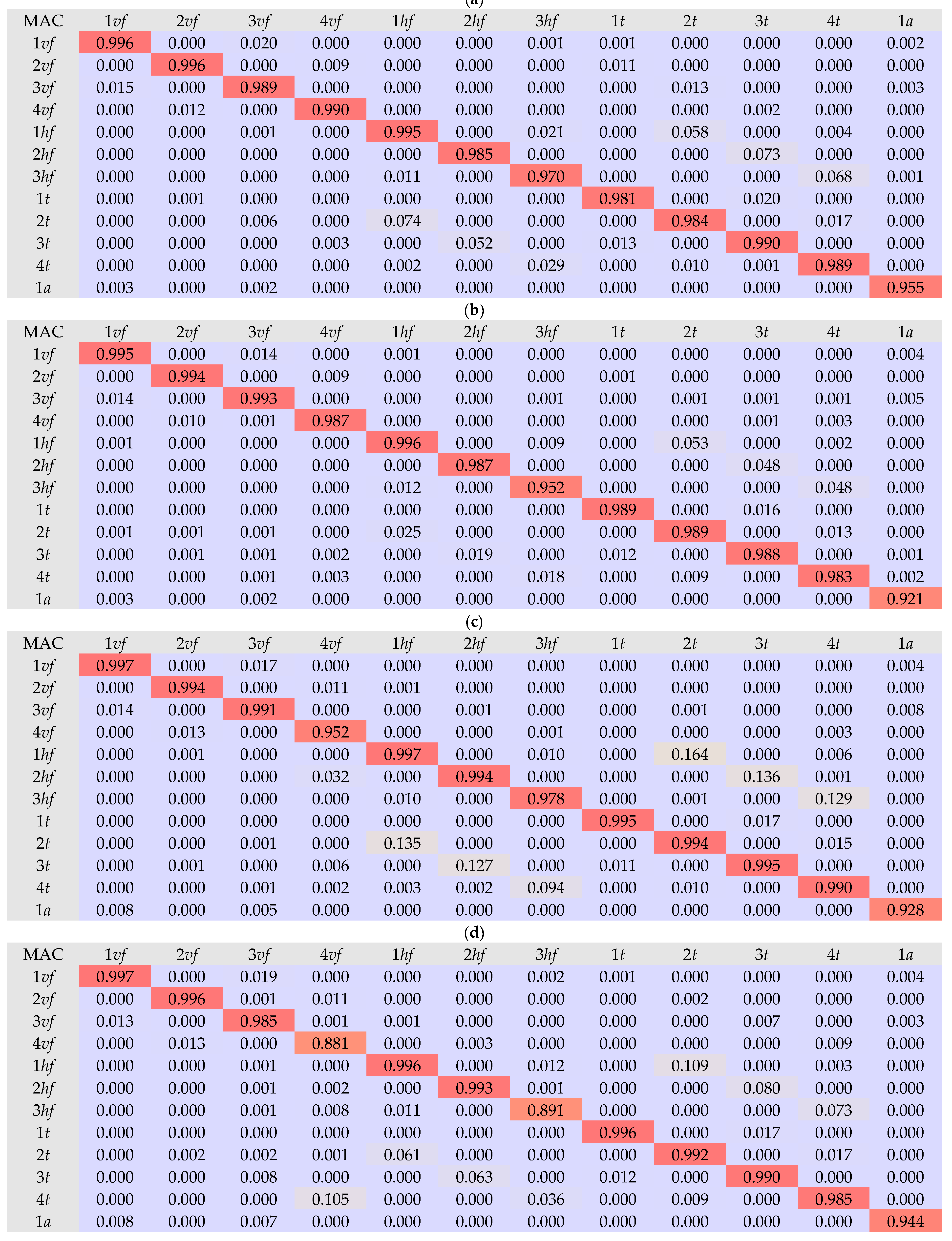
In addition to a visual comparison of vibration modes, a comparison using the MAC (Modal Assurance Criterion) was conducted. The analyses were performed for all four LVL panels. The MAC indicator was presented in both tabular and graphic forms (Figure 12 and Figure 13). The MAC index reached values close to 1, which means a very high agreement between the experimental and numerical modes of natural vibrations.

4. Conclusions

This paper studied the vibration performance of LVL panels. Due to the lightness of these panels, the vibration behaviour is potentially a serviceability concern. For this rea-son, four panels were investigated to measure their dynamic response. Dynamic tests are a non-destructive method and, as such, are more favourable than static tests. The dynamic laboratory tests of the LVL panels were effectively used to determine the elastic and shear moduli of the LVL. The modal properties determined in the experiments were used to identify the elastic properties of the LVL and to validate the numerical models of the LVL slabs. The elastic moduli of the LVL depended on the LVL type (X and R) and on the panel thickness. The elastic modulus of LVL X in the longitudinal direction was lower than the elastic modulus of LVL R in the same direction. The elastic moduli of LVL X in tangential and radial directions were higher than the elastic moduli of LVL R in the same directions. The elastic moduli of the 75 mm LVL R panels were higher than those of the 45 mm LVL R panel. Small differences between the elastic and shear moduli of the P_75_300 and P_75_370 LVL panels differing only in width were observed. These small differences were the result of material variability. The frequencies and the mode shapes of vibration from the numerical model showed a significant correlation with the results of the laboratory tests. The MAC index reached values close to 1, which signifies a very high agreement between the experimental and numerical modes of natural vibrations. The calibrated numerical models of LVL slabs will be used in the future to develop numerical models of composite floors with LVL panels.

Author Contributions

Conceptualization, M.A., M.C., Ł.P. and T.W.; methodology, M.A., M.C., Ł.P. and T.W.; investigation, M.A., M.C., Ł.P. and T.W.; specimen preparation, M.A., M.C., Ł.P. and T.W.; writing—original draft preparation, M.A., M.C., Ł.P. and T.W.; writing—review and editing, M.A., M.C., Ł.P. and T.W.; visualization, M.A., M.C., Ł.P. and T.W. All authors have read and agreed to the published version of the manuscript.

Funding

This research was funded by the Polish Ministry of Science and Higher Education under grant 0412/SBAD/0070.

Institutional Review Board Statement

Not applicable.

Informed Consent Statement

Not applicable.

Data Availability Statement

All data are contained within the article.

Acknowledgments

The authors wish to thank STEICO company for the LVL panels.

Conflicts of Interest

The authors declare no conflict of interest.

References

  1. Tupenaite, L.; Kanapeckiene, L.; Naimaviciene, J.; Kaklauskas, A.; Gecys, T. Timber Construction as a Solution to Climate Change: A Systematic Literature Review. Buildings 2023, 13, 976. [Google Scholar] [CrossRef]
  2. Heräjärvi, H. Wooden buildings as carbon storages–Mitigation or oration? Wood Mater. Sci. Eng. 2019, 14, 291–297. [Google Scholar] [CrossRef]
  3. Musselman, E.S.; Dinehart, D.W.; Walker, S.M.; Mancini, M.L. The effect of holes on the creep behavior and flexural capacity of laminated veneer lumber (LVL) beams. Constr. Build. Mater. 2018, 180, 167–176. [Google Scholar] [CrossRef]
  4. Komorowski, M. Podręcznik Projektowania i Budowania w Systemie STEICO. Podstawy. Fizyka Budowli. Zalecenia Wykonawcze; Forestor Communication: Warsaw, Poland, 2020. (In Polish) [Google Scholar]
  5. Hammad, M.W.; Valipour, H.R.; Ghanbari-Ghazijahani, T.; Bradford, M.A. Timber-timber composite (TTC) beams subjected to hogging moment. Constr. Build. Mater. 2022, 321, 126295. [Google Scholar] [CrossRef]
  6. Wang, X.; Zhang, J.; Wu, P.; Li, Y. Experimental investigation on the flexural and shear behaviour of LVL I-beam strengthened with steel channels. Constr. Build. Mater. 2022, 341, 127719. [Google Scholar] [CrossRef]
  7. Hiziroglu, S. Laminated Veneer Lumber (LVL) as a Construction Material. In Food Technology Fact Sheet; FAPC-163; Oklahoma State University: Stillwater, OK, USA, 2016. [Google Scholar]
  8. Chiniforush, A.A.; Valipour, H.R.; Ataei, A. Timber-timber composite (TTC) connections and beams: An experimental and numerical study. Constr. Build. Mater. 2021, 303, 124493. [Google Scholar] [CrossRef]
  9. Hassan, O.A.B.; Johansson, C.J. Glued laminated timber and steel beams. A comparative study of structural design, economic and environmental consequences. Eng. Des. Technol. 2018, 16, 398–417. [Google Scholar] [CrossRef]
  10. Wilson, J.B.; Dancer, E.R. Gate-to-gate life-cycle inventory of laminated veneer lumber production. Wood Fiber Sci. 2005, 37, 114–127. [Google Scholar]
  11. Mirdad, M.A.H.; Daneshvar, H.; Joyce, T.; Chu, Y.H. Sustainability Design Considerations for Timber-Concrete Composite Floor Systems. Hindawi Adv. Civ. Eng. 2021, 2021, 6688076. [Google Scholar] [CrossRef]
  12. United Nations; the Food and Agriculture Organization of the United Nations. Circularity Concepts in Wood Construction; ECE/TIM/DP/95; Forestry and Timber Section: Geneva, Switzerland, 2023.
  13. Annual and Sustainability Report; Metsä Group: Espoo, Finland, 2022.
  14. Sustainability Report; STEICO: Feldkirchen, Germany, 2020.
  15. The LVL Kitset Portal Frame Solution, hyFRAME LVL Kitset Brochure; Carter Holt Harvey, Futurebuild LVL: Auckland, New Zealand, 2018.
  16. Winchester, N.; Reilly, J.M. The economic and emissions benefits of engineered wood products in a low-carbon future. Energy Econ. 2020, 85, 104596. [Google Scholar] [CrossRef]
  17. Upton, B.; Miner, R.; Spinney, M.; Heath, L.S. The greenhouse gas and energy impacts of using wood instead of alternatives in residential construction in the United States. Bio-Mass Bioenergy 2008, 32, 1–10. [Google Scholar] [CrossRef]
  18. Tellnes, L.G.F.; Eide, S.; Kristjansdottir, T.F.; Kron, M. Assessment of carbon footprint of laminated veneer lumber elements in a six story housing–comparison to a steel and concrete solution. In Proceedings of the International Conference Portugal SB13-Contribution of Sustainable Building to Meet EU 20-20-20 Targets, Guimarães, Portugal, 30 October–1 November 2013; Bragança, L., Mateus, R., Pinheiro, M., Eds.; MULTICOMP-Artes Gráficas, Lda: Estoril, Portugal, 2013; pp. 817–824. [Google Scholar]
  19. Lu, H.R.; El Hanandeh, A.; Gilbert, B.; Bailleres, H. A comparative life cycle assessment (LCA) of alternative material for Australian building construction. MATEC Web Conf. 2017, 120, 02013. [Google Scholar] [CrossRef]
  20. Bakalarz, M.M.; Kossakowski, P.G. Application of Transformed Cross-Section Method for Analytical Analysis of Laminated Veneer Lumber Beams Strengthened with Composite Materials. Fibers 2023, 11, 24. [Google Scholar] [CrossRef]
  21. Hassanieh, A.; Valipour, H.R.; Bradford, M.A. Experimental and analytical behaviour of steel-timber composite connections. Constr. Build. Mater. 2016, 118, 63–75. [Google Scholar] [CrossRef]
  22. Romero, A.; Yang, J.; Hanus, F.; Odenbreit, C. Numerical Investigation of Steel-LVL Timber Composite Beams. Ce/Papers 2022, 5, 21–30. [Google Scholar] [CrossRef]
  23. Chybiński, M.; Polus, Ł. Experimental and numerical investigations of aluminium-timber composite beams with bolted connections. Structures 2021, 34, 1942–1960. [Google Scholar] [CrossRef]
  24. Zhou, Y.; Zhao, Y.; Wang, C.-L.; Zhou, Y.; Zheng, J. Experimental study of the shear performance of H-shaped aluminum-timber composite connections. Constr. Build. Mater. 2022, 334, 127421. [Google Scholar] [CrossRef]
  25. Nie, Y.; Valipour, H.R. Experimental and numerical study of long-term behaviour of timber-timber composite (TTC) connections. Constr. Build. Mater. 2021, 304, 124672. [Google Scholar] [CrossRef]
  26. Nie, Y.; Karimi-Nobandegani, A.; Valipour, H.R. Experimental behaviour and numerical modelling of timber-timber composite (TTC) joints. Constr. Build. Mater. 2021, 290, 123273. [Google Scholar] [CrossRef]
  27. Khorsandnia, N.; Valipour, H.R.; Crews, K. Experimental and analytical investigation of short-term behaviour of LVL–concrete composite connections and beams. Constr. Build. Mater. 2012, 37, 229–238. [Google Scholar] [CrossRef]
  28. Khorsandnia, N.; Valipour, H.; Bradford, M. Deconstructable timber-concrete composite beams with panelised slabs: Finite element analysis. Constr. Build. Mater. 2018, 163, 798–811. [Google Scholar] [CrossRef]
  29. Jaaranen, J.; Fink, G. Experimental and numerical investigations of two-way LVL–concrete composite plates with various support conditions. Eng. Struct. 2022, 256, 114019. [Google Scholar] [CrossRef]
  30. Chorlton, B.; Gales, J. Mechanical performance of laminated veneer lumber and Glulam beams after short-term incident heat exposure. Constr. Build. Mater. 2020, 263, 120129. [Google Scholar] [CrossRef]
  31. Hamm, P.; Richter, A.; Winter, S. Floor vibrations–new results. In Proceedings of the 11th World Conference on Timber Engineering 2010 (WCTE 2010); Ceccotti, A., Ed.; Trees and Timber Institute, National Research Council: Sesto Fiorentino, Italy, 2010. [Google Scholar]
  32. Chiniforush, A.A.; Akbarnezhad, A.; Valipour, H.; Dackermann, U. Dynamic response of steel-timber composite (STC) beams. In Proceedings of the 24th International Congress on Sound and Vibration, London, UK, 23–27 July 2017. [Google Scholar]
  33. Wen, B.; Tao, H.; Shi, B.; Yang, H. Dynamic Properties of Timber–Concrete Composite Beams with Crossed Inclined Coach Screw Connections: Experimental and Theoretical Investigations. Buildings 2023, 13, 2268. [Google Scholar] [CrossRef]
  34. Meng, Z.B.; Ren, X.C.; Chai, S.Q.; Wang, X.; Zhao, T.F.; Gao, F.F.; Wang, S.; Liu, Y. Wood Beam Damage Identification Based on the Curvature Mode and Wavelet Transform. Adv. Civ. Eng. 2023, 1, 2238021. [Google Scholar] [CrossRef]
  35. Gao, Z.; Zhang, X.; Wang, Y.; Yang, R.; Wang, G.; Wang, Z. Measurement of the Poisson’s ratio of materials based on the bending mode of the cantilever plate. BioResources 2016, 11, 5703–5721. [Google Scholar] [CrossRef]
  36. Ross, R.J. Nondestructive Evaluation of Wood; General Technical Report FPL-GTR-238; Department of Agriculture, Forest Service, Forest Products Laboratory: Madison, WI, USA, 2015.
  37. Berczyński, S.; Wróblewski, T. Vibration of Steel–Concrete Composite Beams Using the Timoshenko Beam Model. J. Vib. Control 2005, 11, 829–848. [Google Scholar] [CrossRef]
  38. Berczyński, S.; Wróblewski, T. Experimental Verification of Natural Vibration Models of Steel-Concrete Composite. J. Vib. Control 2010, 16, 2057–2081. [Google Scholar] [CrossRef]
  39. NA to BS EN 1991-1-1:2002; UK National Annex to Eurocode 1: Actions on Structures. British Standards Institution: London, UK, 2005.
  40. EN 1995-1-1; Eurocode 5: Design of Timber Structures-Part 1-1: General-Common Rules and Rules for Buildings. European Committee for Standardization: Brussels, Belgium, 2004.
  41. EKS 10: BFS 2015:6; Swedish National Annex for Application of Eurocodes. The National Board of Housing, Building and Planning: Karlskrona, Sweden, 2015.
  42. Schirén, W.; Swahn, T. Vibrations in Residential Timber Floors. A Comparison Between the Current and the Revised Eurocode 5. Master’s Thesis, Linnaeus University, Växjö, Sweden, 2019. [Google Scholar]
  43. Wróblewski, T.; Pełka-Sawenko, A.; Abramowicz, M.; Berczyński, B. Modeling and analysis of free vibration of steel-concrete composite beams by finite element method. Adv. Manuf. Sci. Technol. 2012, 36, 85–96. [Google Scholar]
  44. Huang, Y.; Chen, S.; Dauletbek, A.; Yang, X.; Wang, J.; Sun, X.; Xie, W.; Wang, Z. Dynamic testing of the elastic modulus and shear modulus of full-scale laminated veneer lumber. BioResources 2021, 16, 8273–8288. [Google Scholar] [CrossRef]
  45. Timoshenko, S. Mechanical Vibration Science; China Machine Press: Beijing, China, 1965. [Google Scholar]
  46. Timoshenko, S. Vibration Problems in Engineering; D. Van Nostrand Company: New York, NY, USA, 1937. [Google Scholar]
  47. Kawrza, M.; Furtmüller, T.; Adam, C. Experimental and numerical modal analysis of a cross laminated timber floor system in different construction states. Constr. Build. Mater. 2022, 344, 128032. [Google Scholar] [CrossRef]
  48. Kouroussis, G.; Fekih, L.B.; Descamps, T. Assessment of timber element mechanical properties using experimental modal analysis. Constr. Build. Mater. 2017, 134, 254–261. [Google Scholar] [CrossRef]
  49. Gsell, D.; Feltrin, G.; Schubert, S.; Steiger, R.; Motavalli, M. Cross-laminated timber plates: Evaluation and verification of homogenized elastic properties. J. Struct. Eng. 2007, 133, 132–138. [Google Scholar] [CrossRef]
  50. Jarosińska, M.; Berczyński, S. Changes in Frequency and Mode Shapes Due to Damage in Steel–Concrete Composite Beam. Materials 2021, 14, 6232. [Google Scholar] [CrossRef] [PubMed]
  51. Kim, C.-J. Comparison of Mode Shapes of Carbon-Fiber-Reinforced Plastic Material Considering Carbon Fiber Direction. Crystals 2021, 11, 311. [Google Scholar] [CrossRef]
  52. Pastor, M.; Binda, M.; Harčarik, T. Modal Assurance Criterion. Procedia Eng. 2012, 48, 543–548. [Google Scholar] [CrossRef]
  53. Shabani, A.; Feyzabadi, M.; Kioumarsi, M. Model updating of a masonry tower based on operational modal analysis: The role of soil-structure interaction. Case Stud. Constr. Mater. 2022, 16, e00957. [Google Scholar] [CrossRef]
  54. Marwala, T. Finite-Element-Model Updating Using Computational Intelligence Techniques; Springer: London, UK, 2010. [Google Scholar]
  55. Abramowicz, M.; Berczyński, S.; Wróblewski, T. Parameter estimation of a discrete model of a reinforced concrete slab. J. Theor. Appl. Mech. 2017, 55, 407–420. [Google Scholar] [CrossRef]
  56. Pełka-Sawenko, A. Zastosowanie Metod Dostrajania Modeli Dyskretnych oraz Transformaty Falkowej do Diagnostyki Uszkodzeń Belek Zespolonych [Application an Identification Technique of Discrete Models and Wavelet Transform for Damage Diagnostics of Composite Beams]; West Pomeranian University of Technology in Szczecin: Szczecin, Poland, 2019. (In Polish) [Google Scholar]
  57. Abramowicz, M.; Berczyński, S.; Wróblewski, T. Modelling and parameter identifcation of steel–concrete composite beams in 3D rigid fnite element method. Arch. Civ. Mech. Eng. 2020, 20, 103. [Google Scholar] [CrossRef]
  58. Szewczyk, P. Wzmacnianie Pod Obciążeniem Stalowo-Betonowych Belek Zespolonych w Analizie Numerycznej i Badaniach Doświadczalnych [Strenghtening of Steel-Concrete Composite Beams under Load in a Numerical Analysis and a Physical Experiment]; West Pomeranian University of Technology in Szczecin: Szczecin, Poland, 2019. (In Polish) [Google Scholar]
  59. Szewczyk, P.; Szumigała, M. Optimal Design of Steel–Concrete Composite Beams Strengthened under Load. Materials 2021, 14, 4715. [Google Scholar] [CrossRef]
  60. Hassanieh, A.; Valipour, H.R.; Bradford, M.A.; Sandhaas, C. Modelling of steel-timber composite connections: Validation of finite element model and parametric study. Eng. Struct. 2017, 138, 35–49. [Google Scholar] [CrossRef]
  61. Sandhaas, C. Mechanical Behaviour of Timber Joints with Slotted-in Steel Plates. Ph.D. Thesis, Delft University of Technology, Delf, Netherlands, 2012. [Google Scholar]
  62. Wdowiak-Postulak, A. Numerical, theoretical and experimental models of the static performance of timber beams reinforced with steel, basalt and glass pre-stressed bars. Compos. Struct. 2023, 305, 116479. [Google Scholar] [CrossRef]
  63. Wdowiak-Postulak, A.; Bahleda, F.; Prokop, J. An Experimental and Numerical Analysis of Glued Laminated Beams Strengthened by Pre-Stressed Basalt Fibre-Reinforced Polymer Bars. Materials 2023, 16, 2776. [Google Scholar] [CrossRef] [PubMed]
  64. Van Beerschoten, W.A. Structural Performance of Post-Tensioned Timber Frames under Gravity Loading. Ph.D. Thesis, University of Canterbury, Christchurch, New Zealand, 2013. [Google Scholar]
  65. Design Guide STEICO LVL/Laminated Veneer Lumber; STEICO: Feldkirchen, Germany, 2019.
Figure 1. Recommended range of and relationship between a and b [40].
Sustainability 16 00166 g001
Figure 2. One of the LVL panels suspended on the stand.
Sustainability 16 00166 g002
Figure 3. (a) Impact hammer (model 086D05, PCB Piezotronics, Depew, NY, USA); (b) Miniature triaxial accelerometer (model 356A01, PCB Piezotronics, Depew, NY, USA).
Sustainability 16 00166 g003
Figure 4. (a) LVL R 45 × 300 × 3000 (P_45_300); (b) LVL R 75 × 300 × 3000 (P_75_300); (c) LVL X 45 × 370 × 3000 (P_45_370X); (d) LVL R 75 × 370 × 3000 (P_75_370).
Sustainability 16 00166 g004
Figure 5. The impact hammer and accelerometer locations on 300 mm-wide panels.
Sustainability 16 00166 g005
Figure 6. The impact hammer and accelerometer locations on 370 mm-wide panels.
Sustainability 16 00166 g006
Figure 7. The mesh used to model the P_75_370 LVL panel.
Sustainability 16 00166 g007
Figure 8. Three main material directions: 1—longitudinal (L), 2—tangential (T), and 3—radial (R).
Sustainability 16 00166 g008
Figure 9. Schematic diagram of the research method used in this study.
Sustainability 16 00166 g009
Figure 10. The vibration modes of the P_75_370 LVL panel predicted in the experiment and in the finite element analysis.
Sustainability 16 00166 g010aSustainability 16 00166 g010b
Figure 11. The vibration modes of the P_75_300 LVL panel predicted in the experiment and in the finite element analysis.
Sustainability 16 00166 g011aSustainability 16 00166 g011b
Figure 12. 3D MAC plots for four LVL panels: (a) P_45_300; (b) P_45_370X; (c) P_75_300; (d) P_75_370.
Sustainability 16 00166 g012
Figure 13. MAC matrixes for four LVL panels: (a) P_45_300; (b) P_45_370X; (c) P_75_300; (d) P_75_370.
Sustainability 16 00166 g013
Table 1. LVL panels.
PanelDimensions [mm]LVLDensity [kg/m3]
P_45_30045 × 300 × 3000R587.7
P_45_370X45 × 370 × 3000X616.6
P_75_30075 × 300 × 3000R665.2
P_75_37075 × 370 × 3000R649.8
Table 2. Elastic moduli E, shear moduli G, and Poisson’s ratios υ adopted for the LVL.
PanelLVLElastic Modulus [MPa]Poisson’s Ratio [–]Shear Modulus [MPa]
E1E2E3υ12υ13υ23G12G13G23
P_45_300R15,6004004000.480.480.2287087090
P_45_370XX13,4007007000.480.480.2290090090
P_75_300R17,5505005000.480.480.2210001000100
P_75_370R17,4005005000.480.480.2210701070100
Table 3. The comparison of the elastic moduli in the longitudinal direction from the optimization process (E1i) and based on Equation (4) (E1e).
PanelLVLElastic Modulus [MPa]
E1iE1eE1e/E1i
P_45_300R15,60015,4870.99
P_45_370XX13,40013,1800.98
P_75_300R17,55017,3900.99
P_75_370R17,40017,1360.98
Table 4. Frequencies obtained from the laboratory tests and the numerical analyses.
PanelMode of
Vibration
Experimental
Frequency fexp
[Hz]
Computational
Frequency fcom
[Hz]
Relative Error
Δ = 100 × (fexpfcom)/fexp
[%]
P_45_3001vf 26.38726.408−0.08
2vf73.44272.3231.52
3vf 136.910140.380−2.53
4vf 222.013228.990−3.14
1hf 153.238157.730−2.93
2hf 345.102354.660−2.77
3hf 541.408562.720−3.94
1t60.54457.8414.46
2t 122.993119.2703.03
3t 190.931187.6201.73
4t 263.068265.990−1.11
1a859.937858.7500.14
P_45_370X1vf 23.76523.907−0.60
2vf 65.49465.560−0.10
3vf 122.550127.480−4.02
4vf 196.190208.380−6.21
1hf 174.117171.1301.72
2hf 374.978372.5700.64
3hf 589.589586.7200.49
1t 48.31947.3641.98
2t 97.27998.402−1.15
3t 152.465156.560−2.69
4t 215.757225.110−4.33
1a 776.164776.560−0.05
P_75_3001vf 43.80343.6600.33
2vf 118.309118.1500.13
3vf 221.364225.430−1.84
4vf 348.757359.890−3.19
1hf 158.088157.5300.35
2hf 350.899355.240−1.24
3hf 557.664570.750−2.35
1t 91.84391.5220.35
2t 187.673187.1000.31
3t 288.364290.610−0.78
4t 397.100405.860−2.21
1a 857.270856.2100.12
P_75_3701vf 43.99444.009−0.02
2vf 119.777119.2500.38
3vf 223.330227.930−2.07
4vf 354.964364.520−2.76
1hf 187.203188.170−0.63
2hf 399.471404.350−1.34
3hf 615.062631.920−2.74
1t 81.19280.1331.17
2t 165.675165.2602.60
3t 260.028260.550−0.21
4t 366.715371.180−1.23
1a 862.618861.4600.06
Disclaimer/Publisher’s Note: The statements, opinions and data contained in all publications are solely those of the individual author(s) and contributor(s) and not of MDPI and/or the editor(s). MDPI and/or the editor(s) disclaim responsibility for any injury to people or property resulting from any ideas, methods, instructions or products referred to in the content.