Abstract
The utilization of biomass for multi-generation systems is garnering significant interest due to its potential in conserving primary energy and mitigating greenhouse gas emissions. However, enhancing its energy efficiency remains a critical challenge. This study introduces an innovative cogeneration system that combines biomass gasification with an externally fired gas turbine, organic Rankine cycle, and absorption refrigeration cycle. It undergoes thorough thermodynamic and exergoeconomic evaluations, with a dual-objective optimization conducted to identify the optimal operational conditions that achieve the highest exergy efficiency while minimizing product cost. The findings reveal that, in the base case, the thermal efficiency, exergy efficiency, and sum unit cost of the product (SUCP) of the system are 66.36%, 32.04%, and 8.71 USD/GJ, respectively. A parametric study illustrates that elevating the air compressor pressure ratio or the temperature difference at the cold end enhances thermal efficiency but reduces exergy efficiency. Additionally, the lowest unit cost of the product is attainable by optimizing the gas turbine inlet temperature. The performance of the system shows negligible sensitivity to the turbine inlet pressure of a bottoming organic Rankine cycle. Finally, optimization demonstrates a 9.7% increase in exergy efficiency and a 1.8% rise in the SUCP compared to the baseline scenario. The study suggests integrating with other energy sources for diversified product outputs and conducting environmental analyses in future research.
1. Introduction
Global energy consumption is maintaining a rapid growth with the acceleration of urbanization and industrialization. According to a survey, fossil fuels satisfy approximately 80% of the world’s energy demand []. Over the past decade, CO2 emissions from the combustion of these fuels have seen an average annual increase of 2.5% []. This extensive consumption of fossil fuels worldwide is a key factor contributing to environmental challenges such as global warming, air pollution, and climate change. Consequently, there is a pressing need to explore renewable and sustainable energy alternatives to decrease reliance on fossil fuels in the foreseeable future.
Among the renewable energy options, biomass stands out due to its minimal CO2 footprint, attributed to its integral role in the carbon cycle. Sources of biomass include forests, agricultural and industrial by-products, sewage, and municipal solid wastes, as well as human and animal waste [,]. Biomass can be transformed into diverse energy formats for heating and electricity generation through several thermochemical conversion techniques, such as direct combustion, pyrolysis, torrefaction, gasification, and liquefaction [,,]. Despite its benefits, the direct combustion of biomass can release significant chemical pollutants, posing greater environmental risks than those associated with natural gas []. However, the gasification of biomass emerges as a viable and economically feasible method for converting solid biomass into cleaner gaseous fuels for energy production []. Derived from the thermochemical conversion of biomass in anaerobic conditions, biochar serves as a carbon-based solid with significant potential as an adsorbent material for environmental pollutant removal, and its incorporation into hydrogen production processes can enhance hydrogen yields [,].
During the gasification process, biomass is converted into gaseous fuels, commonly named syngas, consisting of CO, CO2, CH4, H2, N2, and H2O [,]. The syngas can be used as fuel to generate power via gas turbine (GT) cycles. In the conventional internally fired GT cycles, the combustion products directly pass though the turbine blades to produce work, which requires the installation of expensive gas clean-up systems to avoid fuel injector and route blockages and prevent turbine blades from being damage (such as by erosion, incrustation, and corrosion) []. Moreover, low-calorific-value syngas requires large amounts of air in the combustion process, which may cause the compressor to surge for commercially available gas turbines []. One approach to overcoming the above problems is to use an externally fired gas turbine (EFGT) []. In the EFGT cycle, the combustion process takes place outside the cycle and the high-temperature combustion products transfer heat to the working media through a high-temperature heat exchanger (HTHE) [,]. The EFGT cycle lowers the strict fuel quality requirements without the need for the gas cleaning process and complex fuel compression and injection equipment, which improves the system’s economy and reliability [,]. However, one of the main shortcomings of the biomass gasification-based EFGT cycle is the relatively low energy efficiency; thus, additional waste heat recovery systems should be employed to enhance the performance of such systems [].
As one of the most commonly used waste heat recovery technologies, organic Rankine cycles (ORCs) are usually adopted to convert the thermal energy at low-, medium- or even high-temperature levels into power, with the advantages of simple structure, low maintenance requirements, great flexibility, and better economics [,]. ORCs have also reached a significant level of maturity in being applied to biomass power generation systems []. Recent research has extensively explored the integration of ORCs within biomass-based EFGT combined cycles. Khanmohammadi et al. [] evaluated a cogeneration setup involving a biomass gasifier, an EFGT, an ORC, and a domestic water heater (DWH), highlighting its energy and exergy efficiencies at 24.15% and 16.13%, respectively. Camporeale et al. [] performed a thermo-economic analysis of a biomass-fueled power generation system based on a 1.3 MW EFGT and an ORC. They demonstrated that the incorporation of an ORC enhanced profitability due to improved electric efficiency and revenue. Mondal et al. [] examined the exergoeconomic performance of a biomass gasification-based power plant that integrates an EFGT cycle with a supercritical ORC, achieving energy and exergy efficiencies of 40.77% and 36.30%, respectively. Vera et al. [] investigated a biomass gasifier-powered electricity generation system integrating an EFGT with an ORC, noting a net electrical efficiency of 20.7% using isopentane as the ORC working fluid.
The EFGT cycle has been recognized as a viable technical and economic solution for small-scale, distributed cogeneration systems fueled by biomass [,]. Amirante et al. [] proposed a small-scale combined heat and power (CHP) plant based on EFGT powered by solid and gaseous biomass for rural electrification, with electrical efficiencies ranging between 10% and 17%. Mirandola et al. [] evaluated EFGT power plants at a landfill and green waste disposal site. They obtained a thermal efficiency of 47.00% and a CHP total efficiency of 66.10% for hybrid EFGT configuration when wood was used as fuel. Quan et al. [] found that integrating the EFGT cycle with air gasification yielded an exergy efficiency of 37.1%, surpassing traditional combustion methods. Tavallaei et al. [] applied an EFGT cycle for recovering the associated gas from oil extraction, demonstrating system energy and exergy efficiencies of 27.6% and 35.8%, respectively.
In recent developments aimed at enhancing the performance of biomass-based combined cycles, numerous multi-generation systems have been introduced to transform waste heat into valuable products. El-Sattar et al. [] undertook a thermodynamic study of a multi-generation system featuring an EFGT, an ORC, and an ARC, identifying a peak system thermal efficiency of 43.9% with toluene as the ORC working fluid. Roy et al. [] assessed a biomass-fueled power generation facility incorporating a solid oxide fuel cell (SOFC), an EFGT, and an ORC, from techno-economic and environmental perspectives, documenting system energy and exergy efficiencies of 41.17% and 37.76%, respectively. Roy et al. [] optimized a cogeneration system for power and heating that includes an EFGT, a biomass gasifier, a SOFC, and a heat recovery steam generator (HRSG), achieving an exergy efficiency, levelized cost of energy, and levelized cost of exergy of 46.58%, 0.0454 USD/kWh, and 0.0657 USD/kWh, respectively. Musharavati et al. [] undertook thermodynamic and thermoeconomic evaluations of a biomass-based cogeneration setup for electricity and freshwater production, incorporating a gasifier, an EFGT cycle, and a multi-effect desalination unit, reporting an optimal exergy efficiency and total cost rate of 15.61% and 206.78 USD/h, respectively. Zaman et al. [] evaluated a biomass gasification-based carbon-negative system integrating an EFGT unit, a molten carbonate fuel cell (MCFC), a steam cycle, and an ORC, obtaining a maximum energy efficiency of 50.8% and a minimum levelized electricity price of 0.097 USD/kWh with 90% carbon capture. Ding et al. [] assessed a biomass-based CHP system comprising a gasifier, an EFGT cycle, a Stirling engine, and a S-CO2 cycle coupled with a DWH from exergoeconomic and environmental perspectives, indicating energy and exergy efficiencies of 72.36% and 36.4%, respectively, when utilizing wood as fuel. Almatrafi et al. [] thermodynamically evaluated a trigeneration system comprising a biomass gasifier, a GT cycle, a SRC, and a single-effect ARC. They found that, when using sawdust as a fuel source, the system could achieve energy and exergy efficiencies of 73.5% and 43.4%, respectively. Hai et al. [] present a polygeneration system combined with a supercritical Brayton cycle (SBC), an ORC, and a DWH to recover waste heat from an EFGT driven by biomass fuel. They reported an exergy efficiency of 39.22% and a unit cost of polygeneration at 15.41 USD/GJ. Sharafi Laleh et al. [] developed a multi-generation scheme based on solar energy and biomass gasification technology incorporating a thermal photovoltaic (PVT), an EFGT, an ORC, an S-CO2, a water desalination RO unit, and a PEM electrolyzer. Their findings suggest that this configuration can attain energy and exergy efficiencies of 40.6% and 36.7%, respectively, with a total product cost of 64.6 USD/G. Aghabalazadeh et al. [] assessed a tri-generation system composed of a biomass gasifier, a SRC, an GT cycle, a Kalina cycle, and an ejector refrigeration cycle (ERC) from thermodynamic and exergoeconomic standpoints. They noted that the energy and exergy efficiencies, along with the LCOE, could reach 82.21%, 51.66%, and 41.01 USD/MWh, respectively.
These studies underscore the cogeneration approach as highly effective in improving the energy conversion efficiency of biomass-based combined cycles. Nonetheless, these systems often release substantial energy directly into the atmosphere during the ORC condensation process. To further improve the system efficiency, the ARC can be considered one of the worthwhile options for utilizing condensation heat because of its ability to be driven by various low-temperature heat sources []. Navongxay et al. [] demonstrated an enhanced ORC system by coupling it with an ARC, significantly increasing the energy and exergy efficiencies by 181.38% and 82.97%, respectively, over traditional ORC by replacing the ORC condenser with an ARC. A cascaded ARC-ORC system was introduced by Zhou et al. [] to optimize the utilization of low-grade residual heat for increased power generation, achieving a peak exergy efficiency of 37.21% with R123 as the working fluid. Zoghi et al. [] explored the integration of an ORC with a compression ARC system for diesel engine waste heat recovery, observing total energy and exergy efficiencies of 75.79% and 44.19%, respectively. They concluded that an optimal performance is attainable when the ORC condensation temperature and ARC generator outlet temperature are maintained at 85 °C and 80 °C, respectively. Research by Aghaziarati et al. [] on an ORC integrated cascade refrigeration system indicated a thermal efficiency of 89.39%, which marked a 23.62% improvement over a standalone ORC system.
To enhance the comprehension of recent advancements in the domain, the key studies pertinent to waste heat recovery from a GT cycle are summarized in Table 1. A review of the existing literature reveals that biomass-driven EFGT cycles are often utilized in multi-generation systems aimed at reducing environmental impacts and boosting sustainability. Moreover, the integration of ORC with ARC significantly augments the energy efficiency in utilizing waste heat. Research on the utilization of ORC, ARC, and EFGT cycles, whether standalone or integrated, for the production of cooling and power has been extensively explored. Nonetheless, the thermodynamic and economic efficacy of the cogeneration systems for power and cooling primarily hinge on the design configurations and energy provisioning, influencing the final product output. Investigations into the integration of biomass-fueled EFGT cycles with combined ARC-ORC systems remain scarce, marking an area ripe for further exploration. This research introduces a novel cogeneration configuration that leverages established waste heat recovery technologies to maximize the utilization of biomass energy, offering practical guidelines for applications. Furthermore, this study breaks new ground by designing a fin-and-tube and a plate heat exchanger for the ORC vapor generator and condenser, respectively, a focus not yet fully explored in the field of biomass energy waste heat recovery. The main contributions and objectives of this work can be summarized as follows:

Table 1.
Summary of the recent studies on the components and analyses of biomass gasification-based multi-generation systems.
- To propose a novel biomass gasification-based cogeneration system combined with EFGT, ORC, and ARC.
- To evaluate the proposed system from thermodynamic and exergoeconomic viewpoints.
- To conduct a comprehensive parametric study for identifying the effects of some key operating parameters on the system performance.
- To perform a multi-objective optimization of the proposed system using exergy efficiency and SUCP as the objective functions.
2. System Description
The layout of the cogeneration system under discussion is depicted in Figure 1. This system incorporates an EFGT, a high-evaporation temperature organic Rankine cycle (HT-ORC), a single-effect ARC, and a low-evaporation temperature organic Rankine cycle (LT-ORC).
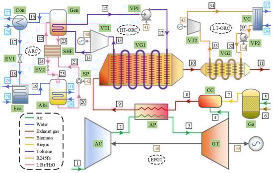
Figure 1.
Schematic diagram of the proposed cogeneration system.
Within the EFGT, ambient air (stream 1) is initially compressed by an air compressor (AC) and, subsequently, this pressurized air (stream 2) is heated in an air preheater (AP) to reach the gas turbine inlet temperature through heat exchange with combustion products (stream 8). The heated air (stream 3) undergoes expansion in the gas turbine to produce electricity. Meanwhile, biomass (stream 6) is fed into the gasifier (Ga) along with air (stream 5) for thermochemical conversion into syngas (stream 7), which then combusts in the combustion chamber (CC) with exhaust air (stream 4) to release heat. The resulting high-temperature flue gas (stream 8) is directed through the AP and vapor generators successively to drive the bottoming cycles.
The HT-ORC and LT-ORC are specifically designed to enhance efficiency and minimize irreversibility by selecting working fluids based on their critical temperatures that are suitable for their respective heat sources. The HT-ORC employs a working fluid that can withstand high decomposition temperatures to utilize the high-temperature segment of the waste heat efficiently. Toluene is identified as a suitable choice for the HT-ORC due to its stability at temperatures around 400 °C [,]. In the HT-ORC circuit, the pressurized organic fluid (stream 12) is heated in a vapor generator (VG1) to a saturated vapor state (stream 13), which is then expanded in a turbine (VT1) to generate power. The exhaust vapor (stream 14) condenses, releasing heat to power an ARC for cooling, with the condensed liquid (stream 15) recirculated to VG1.
The ARC employs LiBr-H2O as the working pair, where the weak solution (stream 22) absorbs heat in the generator, splitting into a strong solution (stream 23) and refrigerant vapor (stream 16). This vapor condenses to liquid (stream 17) in the condenser (Con), then depressurizes and cools in the expansion valve (EV1). After that, the refrigerant (stream 18) absorbs heat in the evaporator (Eva) to produce a cooling capacity and leaves it as the saturated vapor (stream 19). This vapor is absorbed by the strong solution (stream 25) and cooled by the water in the absorber (Abs). The cycle is completed as the weak solution (stream 20) is pumped back to the generator and preheated by exchanging heat with the strong solution in the solution heat exchanger (SHE).
Regarding the LT-ORC, R245fa serves as the working fluid due to its suitability for efficient low-grade waste heat recovery with a decomposition temperature around 250 °C [,], ensuring stability under the designed inlet temperature of the exhaust gas (stream 10). In the LT-ORC loop, organic fluid (stream 32) becomes saturated vapor (stream 33) in the vapor generator (VG2), drives a turbine (VT2) to generate power, and the exhaust vapor (stream 34) is condensed back to liquid (stream 35) in the condenser (VC) before being pressurized and returned to VG2.
3. Mathematical Modeling
3.1. Assumptions
The simulation and modeling of the described system are founded on a set of assumptions, as outlined below [,,]:
- The system operates in a steady state;
- Any changes in kinetic and potential energies within the system are considered insignificant;
- Heat losses from the system components are overlooked;
- There are no significant pressure drops as the fluids move through the various components;
- The composition of ambient air is taken as 21% oxygen and 79% nitrogen by volume;
- Gas mixtures within the system are treated as ideal gases;
- Within the ARC, fluid streams exiting the evaporator and condenser are in a saturated condition, with the output solutions from the generator and absorber presumed to be at equilibrium in terms of temperature and concentration;
- In the ORC, the working fluids exiting the vapor generator and condenser are in saturated vapor and liquid states, respectively;
- The operation of compressors, pumps, and turbines is characterized by constant isentropic efficiencies throughout the simulation.
3.2. Energy Analysis
3.2.1. Biomass Gasifier
This research examines the utilization of an atmospheric downdraft gasifier, with wood chips serving as the fuel and air as the gasification agent. The wood chips and air are used for fuel and gasifying agent, respectively. The equilibrium model is applied for the estimation of syngas composition, which proves to have a good approximation for the gasification process in the downdraft gasifier []. The overall gasification reaction can be expressed as follows [,]:
where w represents the moisture content of the biomass and denotes the kilomoles of oxygen from air involved in the reaction. The coefficients n1 to n6 are the kilomoles of the product constituents.
Biomass moisture content is typically quantified using a mass-based approach (MC), formulated as follows [,]:
where and are the molecular weights of the biomass and water, respectively.
The gasification reaction primarily involves several key chemical processes []:
Equations (3) and (4) coalesce to formulate the water–gas shift reaction []:
The equilibrium constants related to Equations (5) and (6) are as follows []:
where PGa is the the gasification pressure. K1 and K2 are the equilibrium constants, which are calculated as follows []:
where is the universal gas constant and is the temperature in the gasification process. and are the changes of the Gibbs functions for the corresponding reactions, which are defined as follows []:
The energy balance, assuming no heat loss from the gasifier, is established for the gasification process at a specified temperature as follows []:
where represents the formation enthalpy of the jth component and represents the variance in specific enthalpy of the jth component at the gasification temperature compared to the reference temperature T0.
3.2.2. Combustion Chamber
Within the combustion chamber, syngas derived from the biomass gasification undergoes a reaction with the air’s oxygen content, assumed to occur under complete combustion conditions and characterized as follows []:
where is the kilomoles of the oxygen entering the combustion chamber.
An adiabatic assumption for the combustion process allows for the following energy balance equation []:
where denotes the molar quantities of the jth component within the air, syngas, and exhaust gas.
3.2.3. Other System Components
The formulation of the steady-state governing equations encompasses mass, energy, and component concentration balances, described by [] as follows:
where x is the mass concentration of LiBr in the solution.
The mass and energy balance equations relevant to the system components are systematically outlined in Table 2.
Table 2.
Mass and energy balance equations for the system components.
3.3. Exergy Analysis
The formulation for the exergy balance within the system is as follows []:
where and denote the input fuel rate and output product rate, respectively. and correspond to the exergy destruction rate and exergy loss rate, respectively. The detailed exergy balance equations for the system’s components are provided in Table 3.
Table 3.
Exergy balance equations for the system components.
For the processes involved in the present work, the kinetic and potential exergies can be neglected. Thus, the specific exergy of any stream can be defined as follows []:
The formulation for physical exergy is given by [] as follows:
For mixtures of ideal gases, the expression for chemical exergy is provided by [] as follows:
where denotes the molar fraction of the ith component and represents its standard chemical exergy.
The specific chemical exergy of biomass is determined by [] as follows:
where is the ratio of the chemical exergy to the lower heating value (LHV) of the organic fraction of biomass, calculated via the equation below, incorporating the mass fractions of oxygen (MO), carbon (MC), and hydrogen (MH) within the biomass []:
The exergy efficiency () and exergy destruction ratio () for the kth component are described by the equations below []:
3.4. Exergoeconomic Analysis
Exergoeconomic analysis integrates the disciplines of exergy analysis and economic evaluation to elucidate the cost generation mechanism and to determine the cost per unit of exergy for products. The formulation for the cost balance of the kth component is given by [] as follows:
In which,
where denotes the cost rate (USD/h), c is the cost per unit of exergy (USD/GJ), and is the total cost rate of the kth component including capital investment and operating and maintenance costs. Detailed cost balance and supplementary equations for each system component are catalogued in Table 4.
Table 4.
Cost balance and auxiliary equations for the system components.
The definitions for the average unit cost of the fuel (), unit cost of the product (), and cost of exergy destruction () for the kth component are as follows []:
The relative cost difference (rk) and exergoeconomic factor (fk) for the kth component are characterized by the following definitions []:
The methodology for translating capital expenses into a cost rate is expressed through the following equation []:
where represents the maintenance factor (1.06), N is the number of operating hours annually (7000), and indicates the capital cost of the kth component. The capital recovery factor (CRF) is derived using the formula presented below []:
where ir denotes the annual interest rate (15%) and nt is the lifetime of the system (20 years).
The capital costs associated with the system components are determined using the cost functions presented in Appendix B, with all costs referenced to a specific base year and adjusted to current values using the Chemical Engineering Plant Cost Index (CEPCI) []:
For estimating the capital costs associated with heat exchangers, it is essential to first calculate their heat transfer areas (), which is achieved through the equation below involving the logarithmic mean temperature difference () and the heat transfer coefficient (Uk) []:
Detailed methodologies for computing heat transfer coefficients are available in Appendix A.
3.5. Overall Performance Assessment
The thermal efficiency and exergy efficiency of the cogeneration system are, respectively, described by the equations below:
The sum unit cost of the product (SUCP) is selected as the exergoeconomic performance criteria of the proposed system, which are formulated as follows:
4. Results and Discussion
4.1. Model Validation
The validation of the mathematical models developed for this study was carried out by comparing the simulation outcomes for various subsystems, including EFGT, ORC, and ARC, against findings reported in the existing literature. The comparisons, as detailed in Table 5, Table 6, Table 7 and Table 8, reveal a notable consistency between the results of this investigation and those previously documented.
Table 5.
Results comparison between the present work and Ref. [] for the EFGT cycle under the same operating conditions ( = 9, = 0.87, = 0.89, T3 = 1400 K, = 3%, = 1.5%, = 1%).
Table 6.
Comparison of the component percentages of the syngas obtained from the present work and those reported in the literature (wood-CH1.44O0.66, MC = 20%, TGa = 1073.15 K).
Table 7.
Results comparison between the present study and Ref. [] for the ORC using R245fa as the working fluid under the same operating conditions (Peva = 1492.3 kPa, Tcon = 304.44 K, = 10 kW).
Table 8.
Results comparison between the present study and Ref. [] for the single-effect LiBr-H2O ARC under the same operating conditions (Tgen = 87.8 °C, Teva = 7.2 °C, Tabs = TCon = 37.8 °C, = 0.7, = 1 kg/s).
4.2. Base Case Results
The simulation inputs for these subsystems are detailed in Table 9, enabling the simulations of the proposed system through the resolution of the outlined equations. The thermodynamic and economic characteristics of each stream within the system are catalogued in Table 10, serving as the foundation for subsequent performance evaluations of the cogeneration system. The distribution of critical exergy and exergoeconomic metrics across various system components is provided in Table 11, revealing superior exergy efficiencies in the gas turbine and air compressor, primarily due to their elevated isentropic efficiencies reducing irreversibility. Conversely, the absorber exhibits the least effective performance. Furthermore, the investment cost rates exhibit the air preheater as the most expensive component at approximately 18.13 USD/h, with the air compressor and biomass gasifier following at 12.68 USD/h and 11.25 USD/h, respectively. The air preheater and air compressor have higher exergoeconomic factor values of about 62.11% and 64.85%, respectively, indicating that the investment cost rate is the main source of the total cost rate for each component.
Table 9.
Input parameters for the cogeneration system.
Table 10.
Thermodynamic properties and costs of the streams for the system.
Table 11.
Exergy and exergoeconomic factors for the system.
Figure 2 portrays the main components’ contributions to the overall exergy destruction rate of the system. The combustion chamber, marked by the highest exergy destruction rate, accounts for 37.71% of the system’s total exergy destruction, primarily due to the various sources of irreversibility, including combustion, mixing, and temperature gradients. The biomass gasifier follows, with syngas production through irreversible chemical transformations contributing to its notable exergy destruction. In terms of the bottoming HT-ORC, ARC, and LT-ORC, the major exergy destruction rates are observed in VG1, the generator, and VG2, contributing 10.21%, 3.01%, and 2.25% to the total exergy destruction, respectively, with corresponding exergy destruction rates of 904.67 kW, 266.12 kW, and 199.66 kW.
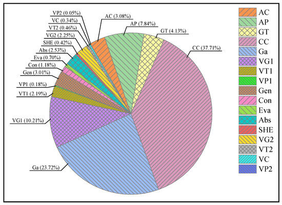
Figure 2.
Contribution of different components in the exergy destruction rate.
Figure 3 details the principal components’ shares in the exergy destruction cost, identifying the CC and VG1 as the leading sources. This pattern is attributed to the significant exergy destruction rates and cost rates of the fuel associated with these components. Furthermore, the low exergoeconomic factors of the CC and VG1, at 16.33% and 34.32%, respectively, suggest that the cost rate of exergy destruction predominates over the investment cost rate as the principal component of the total cost rate.
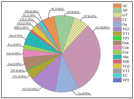
Figure 3.
Contribution of different components in the cost of exergy destruction.
Table 12 details the outcomes of a thermodynamic and exergoeconomic analysis performed on the cogeneration system under discussion. The findings, as outlined in Table 11, demonstrate that the system is capable of generating a net power output of 4270.2 kW and a cooling capacity of 3658.4 kW. The overall thermal efficiency, exergy efficiency, and SUCP are calculated to be 66.36%, 32.04%, and 8.71 USD/GJ, respectively. Specifically, the turbines in the HT-ORC and LT-ORC contribute power outputs of 1159.85 kW and 178.34 kW, respectively. Meanwhile, the power consumed by the HT-ORC and LT-ORC pumps are 55.85 kW and 12.17 kW, respectively. The HT-ORC is noted for its significantly higher power generation compared to the LT-ORC because it recovers most of the waste heat discharge from the EFGT cycle. Furthermore, the cost per unit of electricity generated by the LT-ORC turbine (25.65 USD/GJ) is considerably higher than that of the HT-ORC turbine (10.95 USD/GJ) and the gas turbine (6.99 USD/GJ). This suggests that unit power generation costs decrease with the scale of operation, enhancing economic viability for larger-scale applications.
Table 12.
Thermodynamic and exergoeconomic evaluation results of the base case.
4.3. Parametric Study
4.3.1. Effect of Air Compressor Pressure Ratio on the System Performance
Figure 4 illustrates the influence of the air compressor pressure ratio (PRAC) on the overall performance of the system. It is observed that, with an increase in PRAC, there is a corresponding rise in thermal efficiency, SUCP, and the net power and cooling outputs, while a decline in exergy efficiency is noted. This phenomenon can be attributed to the elevated temperature of exhaust gases exiting the air preheater, which is induced by an increased PRAC under a constant CETD. Consequently, this enhances the availability of waste heat for the bottoming cycles, thereby augmenting both the net power output and cooling capacity. Nevertheless, a reduction in exergy efficiency is noted, as the rise in fuel exergy surpasses the increase in output exergy.
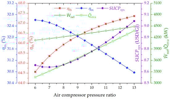
Figure 4.
Effect of air compressor pressure ratio on the thermal efficiency, exergy efficiency, SUCP, net power output, and cooling capacity of the system.
4.3.2. Effect of Gas Turbine Inlet Temperature on the System Performance
The influence of the gas turbine inlet temperature (GTIT) on the system performance is depicted in Figure 5. From this figure, it is evident that both thermal and exergy efficiencies experience significant growth as GTIT increases, whereas there is a notable decline in both the net power output and cooling capacity. Additionally, the system’s SUCP initially decreases, reaching its lowest point at 8.71 USD/GJ, before ascending. The rationale behind these trends lies in the heightened enthalpy differential across the gas turbine with rising GTIT, leading to marked reductions in the mass flow rates of both air and flue gases under a fixed EFGT power capacity. This scenario results in a diminished thermal heat supply to the bottoming cycles, thereby reducing the net power output and cooling capacity. Meanwhile, the increased GTIT leads to reduced biomass consumption for the same power output, thus elevating both the thermal and exergy efficiencies of the EFGT cycle. Given that the efficiencies of the bottoming cycles remain unchanged due to fixed operational parameters, the system’s overall thermal and exergy efficiencies increase.
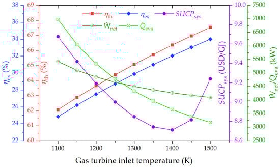
Figure 5.
Effect of gas turbine inlet temperature on the thermal efficiency, exergy efficiency, SUCP, net power output, and cooling capacity of the system.
4.3.3. Effect of Cold-End Temperature Difference on the System Performance
Figure 6 presents the influence of the cold-end temperature difference (CETD) on the performance metrics of the cogeneration system. An upward trend is noted in the thermal efficiency, net power production, and cooling output with an increase in CETD, whereas the exergy efficiency exhibits a downward trend. Additionally, the SUCP initially decreases to its lowest value before it begins to rise. This behavior can be attributed to the growth in both the temperature and mass flow rate of flue gas as CETD increases, which boosts the thermal heat availability for the bottoming cycles, thereby facilitating an enhanced power generation and cooling output. Conversely, the exergy destruction escalates markedly with increasing CETD, primarily due to greater irreversible losses from larger temperature differences during heat transfer within system components. Moreover, a higher CETD necessitates increased biomass consumption. Consequently, the system’s exergy efficiency diminishes as the growth in biomass exergy surpasses the rise in output exergy.
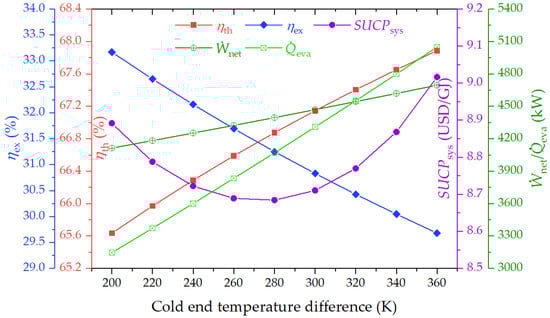
Figure 6.
Effect of cold-end temperature difference on the thermal efficiency, exergy efficiency, SUCP, net power output, and cooling capacity of the system.
4.3.4. Effect of HT-ORC Turbine Inlet Pressure on the System Performance
Figure 7 examines the influence of the HT-ORC turbine inlet pressure on the system performance. The figure indicates that, with an increment in the HT-ORC turbine inlet pressure, there is a marginal increase in both thermal and exergy efficiencies, along with a slight rise in the net power output. Conversely, the SUCP and cooling capacity experience a minor reduction. These observations can be attributed to the enhanced efficiency of the HT-ORC resulting from the increased turbine inlet pressure, which, in turn, leads to a boost in power output. However, the cooling capacity diminishes as a consequence of the reduced thermal heat supply to the ARC unit. When considering the aggregate power and cooling outputs, the increases in energy and exergy efficiencies are attributed to the more substantial rise in power relative to the cooling capacity, alongside the predominant influence of power generation on exergy efficiency.
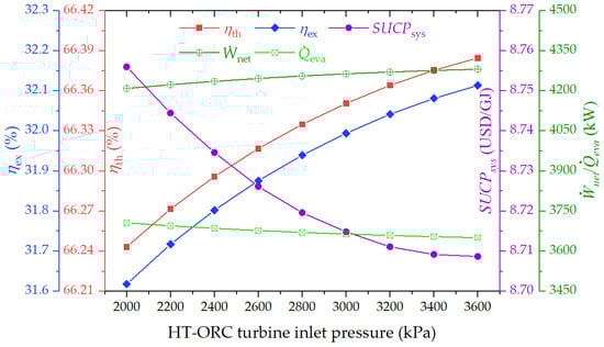
Figure 7.
Effect of HT-ORC turbine inlet pressure on the thermal efficiency, exergy efficiency, SUCP, net power output, and cooling capacity of the system.
4.3.5. Effect of HT-ORC Condensation Temperature on the System Performance
Figure 8 illustrates the impact of HT-ORC condensation temperature on the system performance. It can be observed that, with an elevation in the HT-ORC condensation temperature, both exergy efficiency and SUCP exhibit a slight reduction, whereas thermal efficiency initially increases, reaching a peak, before subsequently declining. This trend is attributed to a decrease in the HT-ORC efficiency and an augmentation in the amount of condensation heat available for powering the ARC, leading to a reduction in the power output but an increase in the cooling capacity. These changes imply a modification in the system’s energy efficiency, with the drop in exergy efficiency primarily stemming from the diminished generation of high-grade power, a key contributor to exergy efficiency.
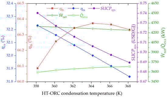
Figure 8.
Effect of HT-ORC condensation temperature on the thermal efficiency, exergy efficiency, SUCP, net power output, and cooling capacity of the system.
4.3.6. Effect of Exhaust Gas Temperature at the Outlet of VG1 on the System Performance
Figure 9 depicts the consequences of altering the exhaust gas temperature at the outlet of VG1 (T10) on the system performance. An increase in T10 is associated with declines in thermal efficiency, exergy efficiency, net power output, and cooling capacity. The primary reason behind this trend is that a higher T10 leads to a reduced thermal heat supply to the HT-ORC and an enhanced heat transfer to the low-temperature LT-ORC, consequently lowering the total net power due to the higher efficiency of HT-ORC relative to the LT-ORC. Moreover, a decrease in the amount of condensation heat directed towards the ARC unit results in a reduced cooling capacity. Hence, the overall thermal and exergy efficiencies of the system decline as a direct result of the decreased net power generation and cooling output.
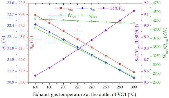
Figure 9.
Effect of exhaust gas temperature at the outlet of VG1 on the thermal efficiency, exergy efficiency, SUCP, net power output, and cooling capacity of the system.
4.3.7. Effect of LT-ORC Turbine Inlet Pressure on the System Performance
The impact of LT-ORC turbine inlet pressure on the system performance is illustrated in Figure 10. Observations indicate that variations in the LT-ORC turbine inlet pressure exert a minimal impact on the overall system performance. Slight enhancements are noted in thermal and exergy efficiencies, SUCP, and net power generation as the LT-ORC turbine inlet pressure rises. The primary reason for this trend is the relatively modest contribution of the LT-ORC-generated power to the system’s total power output. Additionally, the efficiency of LT-ORC experiences marginal improvement with elevated turbine inlet pressure.
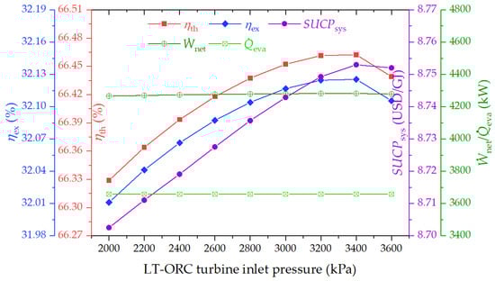
Figure 10.
Effect of LT-ORC turbine inlet pressure on the thermal efficiency, exergy efficiency, SUCP, net power output, and cooling capacity of the system.
4.3.8. Effect of Biomass Gasification Temperature and Moisture Content on the System Performance
Figure 11 depicts the impact of the gasification temperature and moisture content of biomass on the molar fraction of each composition and LHV of syngas. It can be seen that, in all cases, the percentage of N2 in syngas is the highest, while the percentage of CH4 is the lowest. As shown in Figure 11a, the percentages of H2, CO, and CO2 decrease as the gasification temperature rises and an increase in the equivalence ratio can be observed. This trend is primarily due to the necessity for additional air to sustain elevated gasification temperatures at a consistent moisture content, enhancing the partial oxidation of biomass. This process leads to a higher production of CO2 and H2O, while diminishing the formation of more valuable gases such as CO, CH4, and H2, thereby lowering the heating value of syngas. However, the molar fraction of CO2 decreases due to the increase in the total number of moles of producer gas.
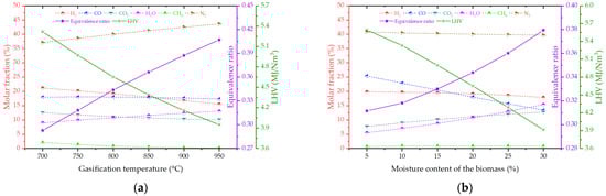
Figure 11.
Effect of the (a) gasification temperature and (b) moisture content of biomass on the molar fraction, equivalence ratio, and LHV.
Figure 11b examines the impact of moisture content in wood chips on the composition and LHV of producer gas at a constant gasification temperature of 800 °C. The figure reveals that the proportions of CO2 and H2O in the producer gas increase with higher moisture levels. This phenomenon can be explained by the enhanced water–gas shift reaction, triggered by increased moisture, which elevates the levels of CO2 and H2 while decreasing the CO concentration. Meanwhile, methane production is enhanced by the process described in Equation (5). However, an increase in water vapor contributes to a higher total mole count of the producer gas, resulting in a drop in the mole fraction of H2.
Figure 12 presents the influence of the gasification temperature and moisture content of biomass on the system performance. The analysis revealed that elevations in both the gasification temperature and biomass moisture content lead to reductions in the thermal and exergy efficiencies of the system, whereas the net power output and cooling capacity experience growth. This phenomenon is attributed to the diminished LHV of the syngas resulting from higher gasification temperatures and moisture levels, necessitating greater biomass consumption. This increase in biomass usage adversely affects the power generation efficiency of the EFGT cycle and elevates the mass flow rate of exhaust gas. Given that the efficiencies of the bottoming ORC and ARC remain constant, the overall thermal and exergy efficiencies of the system decline, while the power and cooling output increase.
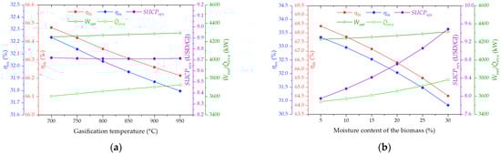
Figure 12.
Effect of the (a) gasification temperature and (b) moisture content of biomass on the thermal efficiency, exergy efficiency, SUCP, net power output, and cooling capacity of the system.
4.4. Sensitivity Analysis
Figure 13 illustrates the sensitivity analysis of key design parameters on thermal efficiency, exergy efficiency, and SUCP. In Figure 13a, it can be observed that T10 and T3 exert the most significant influence on thermal efficiency. As T10 varies from −10% (425.84 K) to +20% (567.78 K), the system’s thermal efficiency decreases from 70.57% to 57.80%. Conversely, as T3 varies from −30% (980 K) to +5% (1470 K), the thermal efficiency increases from 59.91% to 67.20%. Additionally, T3 exhibits the most pronounced impact on exergy efficiency in the system, followed by T10 and CETD, as illustrated in Figure 13b. The sensitivity analysis of SUCP in Figure 13c indicates that biomass price, T3, CETD, and T10 are the primary influencing factors. Notably, an increase in biomass price from −30% to +40% results in a rise in SUCP from 7.45 to 10.81. Compared to other parameters, P13 and P33 have the least significant effect on system performance.
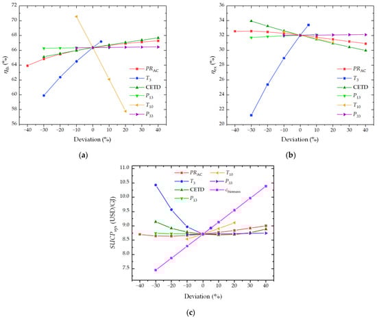
Figure 13.
Sensitivity analysis of the proposed system regarding (a) thermal efficiency, (b) exergy efficiency, and (c) SUCP.
4.5. Multi-Objective Optimization
To identify the optimal performance and operational parameters of the system, a comprehensive multi-objective optimization incorporating both thermodynamic and economic criteria is executed. The optimization framework employs exergy efficiency and SUCP as the objective functions. The key operational parameters are defined as decision variables, with their respective ranges detailed in Table 13. A specialized script is crafted in MATLAB R2018b software utilizing the Genetic Algorithm (GA) for the dual-objective optimization task. The outcomes are represented as a Pareto frontier in Figure 14, where each point signifies an optimal configuration, highlighting the inherent trade-off between exergy efficiency and SUCP. Initial increases in exergy efficiency correlate with moderate SUCP increments, which subsequently escalate sharply. The apex of exergy efficiency is marked at point A, whereas the lowest SUCP is observed at point B.
Table 13.
Selected decision variables of the proposed system and their limits.
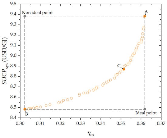
Figure 14.
Distribution of the Pareto optimal solutions.
For determining the ultimate optimal solution, the TOPSIS (Technique for Order of Preference by Similarity to Ideal Solution) decision-making process is employed to pinpoint the optimal choice among the Pareto frontier solutions. This technique seeks alternatives that are closest to the ideal solution (the best value for each objective function) and most distant from the non-ideal solution (the worst value for each objective function). The decision matrix is formulated, and distances to the ideal and non-ideal solutions are calculated, according to specified Equations (41)–(44) [].
The relative closeness can be defined as follows:
The selection process culminates in choosing a solution that maximizes Cli, leading to the designation of point C as the chosen optimal solution. Detailed values of the objective functions and decision variables for points A, B, and C along the Pareto frontier are outlined in Table 14.
Table 14.
The values of decision variables and objective functions at points A, B, and C.
To comprehensively investigate the impact of decision variables, the scattered distribution of these variables with respect to population size is presented in Figure 15a–g. Within the figure, the upper and lower boundaries of the decision variables are delineated by red dotted lines. The analysis in Figure 15a reveals an optimal pressure ratio range of approximately 6–7.5 for attaining the highest exergy efficiency coupled with the lowest cost. Similarly, Figure 15b illustrates the distribution of GTIT, indicating that maintaining this parameter towards its upper limit yields more favorable outcomes. Specifically, a higher GTIT corresponds to increased exergy efficiency and decreased unit product costs; this is consistent with findings from Figure 5, where a rise in GTIT correlates with efficiency gains and cost reductions. Furthermore, Figure 15d,e demonstrate that the distributions of outcomes for P13 and T10 are concentrated within the center of specified ranges, while CETD and P33 contributions are predominantly located on the lower side of the specified range, as depicted in Figure 15c,g. The optimal pressure ratio ranges for P13, T10, CETD, and P33 are observed to be 3200–3500 kPa, 430–450 K, 200–240 K, and 3000–3200 kPa, respectively.
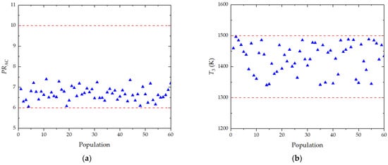
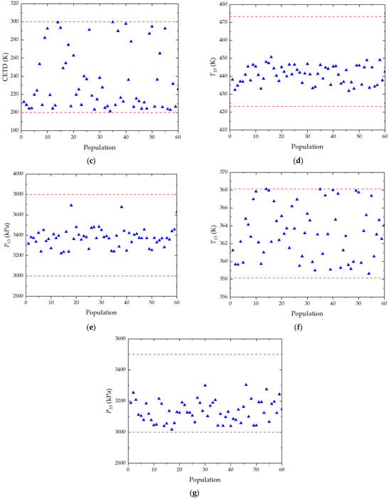
Figure 15.
Scatter distribution of decision variables with population: (a) PRAC; (b) T3; (c) CETD; (d) T10; (e) P13; (f) T15; and (g) P33.
5. Conclusions
This study conducted an extensive thermodynamic and exergoeconomic analysis of a biomass gasification-based cogeneration system, incorporating an EFGT, a SRC, an ORC, and a single-effect ARC. Through detailed parametric analysis and multi-objective optimization, this research aims to provide a thorough insight into the system’s functionality. The key findings are summarized below:
- (1)
- The proposed system is capable of generating a net power output of 4270.2 kW and a cooling capacity of 3658.4 kW, with a respective thermal efficiency, exergy efficiency, and SUCP of 66.36%, 32.04%, and 8.71 USD/GJ.
- (2)
- The combustion chamber is identified as the primary source of exergy destruction within the system, closely followed by the biomass gasifier. Additionally, the combustion chamber incurs the highest exergy destruction costs, with the vapor generator ranking second.
- (3)
- The gas turbine inlet temperature exerts a significant influence on system performance. An increase in this temperature from 1100 K to 1500 K notably enhances both thermal and exergy efficiencies by 8.8% and 36.8%, respectively, with the SUCP reaching its lowest at approximately 1400 K.
- (4)
- Elevations in the air compressor pressure ratio or cold end temperature difference are associated with enhanced thermal efficiency but reduced exergy efficiency. Moreover, such adjustments offer potential for SUCP optimization.
- (5)
- Enhancements in thermodynamic and economic outcomes are attainable through a reduction in the exhaust gas temperature at the VG1 outlet. The inlet pressure adjustments for the HT-ORC or LT-ORC turbines exhibit a minimal impact on the overall system performance.
- (6)
- Under optimal conditions, the system’s exergy efficiency can be increased by 9.7%, despite an accompanying 1.8% rise in SUCP, illustrating the delicate balance between enhancing system efficiency and managing cost implications.
The limitations of this study include the lack of an environmental assessment of the proposed system, with future endeavors aimed at integrating with other energy sources or subsystems to produce more types of products. Future research directions encompass comparative investigations of different biomass feedstocks (such as paper, wood, paddy husk, and municipal solid waste) in the gasifier on system performance. Moreover, other types of ORC working fluids, including pure fluids and zeotropic mixtures, should be further studied to find out the optimal type. Various power-generation systems, such as transcritical ORCs and supercritical CO2 Brayton cycles, can be selected to better match the heat sources and improve the energy utilization efficiency. Additionally, an evaluation of the feasibility of the proposed system in practical applications and experimental validations with real-world devices are also imperative for future studies.
Author Contributions
Conceptualization, J.R.; methodology, J.R. and B.W.; software, J.R. and B.W.; validation, J.R.; formal analysis, J.R. and X.W.; investigation, J.R. and W.H.; writing—original draft preparation, J.R. and W.H.; writing—review and editing, X.W. and Z.Q.; project administration, Z.Q.; funding acquisition, Z.Q. All authors have read and agreed to the published version of the manuscript.
Funding
This research was funded by the Hubei Province Technological Innovation Special Fund, grant number 2019BKJ002.
Institutional Review Board Statement
Not applicable.
Informed Consent Statement
Not applicable.
Data Availability Statement
Data are contained within the article.
Conflicts of Interest
The authors declare no conflicts of interest.
Nomenclature
| A | area (m2) | CETD | cold-end temperature difference |
| cost per exergy unit (USD·GJ−1) | con | condenser | |
| cost rate (USD·h−1) | COP | coefficient of performance | |
| ex | exergy per unit mass (kW·kg−1) | CRF | capital recovery factor |
| exergy rate (kW) | EFGT | externally fired gas turbine | |
| f | exergoeconomic factor | EV | expansion valve |
| h | specific enthalpy (kJ·kg−1) | eva | evaporator |
| ir | annual interest rate (%) | GA | genetic algorithm |
| K | equilibrium constant | Ga | gasifier |
| mass flow rate (kg·s−1) | gen | generator | |
| n | kilomoles of component (kmol) | GT | gas turbine |
| N | annual operating hours (h) | GTIT | gas turbine inlet temperature |
| nt | lifetime of the system | is | isentropic |
| P | pressure (kPa) | IHE | internal heat exchanger |
| heat transfer rate (kW) | LHV | lower heating value | |
| r | relative cost difference | MW | molecular weight |
| s | specific entropy (kJ·kg−1·K−1) | ORC | organic Rankine cycle |
| T | temperature (K) | PR | pressure ratio |
| U | heat transfer coefficient (W·m−2·K−1) | SHE | solution heat exchanger |
| power (kW) | SP | solution pump | |
| exergy destruction ratio (%) | SUCP | sum unit cost of the product | |
| Z | investment cost (USD) | VC | vapor condenser |
| investment cost rate (USD/h) | VG | vapor generator | |
| VP | organic fluid pump | ||
| Subscript and abbreviations | VT | vapor turbine | |
| 0 | dead state | ||
| 1, 2, … | state points | Greek Symbols | |
| abs | absorber | difference | |
| AC | air compressor | η | efficiency |
| AP | air preheater | ε | heat exchanger effectiveness |
| ARC | absorption refrigeration cycle | maintenance factor | |
| CC | combustion chamber | chemical exergy coefficient | |
Appendix A
In the HT-ORC and LT-ORC, vapor generators and condensers serve as crucial components and their selection should meet the requirements of thermal stability, low resistance, compact size, and high heat-transfer efficiency. Considering the large difference in heat transfer coefficients between the hot sides (exhaust gas) and the cold sides (working fluids), fin-and-tube heat exchangers (FTHE) are chosen as the vapor generators []. Specifications regarding the dimensions of the FTHE are presented in Table A1.
Table A1.
Geometric dimensions of the fin-and-tube heat exchanger.
Table A1.
Geometric dimensions of the fin-and-tube heat exchanger.
| Item | Value | Unit |
|---|---|---|
| Tube inner diameter, di | 20 | mm |
| Tube outer diameter, do | 25 | mm |
| Tube pitch, STu | 60 | mm |
| Fin height, HF | 12.5 | mm |
| δF | 1 | mm |
| Fin pitch, YF | 4 | mm |
| Fouling factor | ||
| Exhaust gas, rexh | m2·K−1·W | |
| Refrigerant (liquid), rliq | m2·K−1·W | |
| Refrigerant (vapor), rvap | m2·K−1·W | |
| Refrigerant (two-phase), rtp | m2·K−1·W | |
| Tube row alignment | Staggered type | |
| Tube and Fin material | Stainless steel 316L | |
In each vapor generator, it is mainly divided into a preheated zone and evaporation zone according to the state of the working fluid. The overall heat transfer coefficient for each zone can be calculated using the formula below []:
where αi and αo refer to the heat transfer coefficient inside and outside the tubes, respectively; γ indicates the rib effect coefficient; λTu represents the thermal conductivity of the tube material; ri and ro stand for the fouling resistances inside and outside the tube, respectively; and ηo denotes the outside overall surface efficiency.
The plate heat exchanger (PHE) is suitable for the condenser of ORC, facilitating heat transfer between the low-pressure working fluid and the cooling water []. The dimensions pertinent to the PHE are provided in Table A2.
Table A2.
Geometric dimensions of the plate heat exchanger.
Table A2.
Geometric dimensions of the plate heat exchanger.
| Item | Value | Unit |
|---|---|---|
| Effective channel length, Le | 1250 | mm |
| Width of flow channel, Wch | 550 | mm |
| Plate thickness, δPl | 0.5 | mm |
| Mean flow channel gap, bch | 5 | mm |
| Corrugation pitch, Pco | 15 | mm |
| Chevron angle, β | π/3 | - |
| Plate material | Stainless steel 316L | |
The condenser is segmented into a precooled zone and a condensation zone, with the overall heat transfer coefficients for each zone of the plate heat exchanger specified accordingly []:
where αhot and αcold are the convection heat transfer coefficients for the hot side and cold side, respectively; δPl is the thickness of plate; and λPl is the thermal conductivity of the plate material.
In the two-phase regions of each vapor generator and condenser, the working fluid properties are subject to variations correlating with the vapor quality. To accurately predict heat transfer coefficients, these two-phase sections are discretized into 50 segments, allowing for the assumption of constant properties within each segment. The methodologies for computing the heat transfer coefficients for both the vapor generators and condensers are detailed in Table A3.
Table A3.
The correlations used to calculate the heat transfer coefficients of FTHE and PHE.
Table A3.
The correlations used to calculate the heat transfer coefficients of FTHE and PHE.
| Component | Heat Transfer Coefficient Correlation |
|---|---|
| Vapor generator | Young correlation for single-phase flow in shell side []: |
| Gnielinski correlation for single-phase flow in the tube side []: | |
| For liquid state: | |
| For vapor state: | |
| Liu–Winterton correlation for two-phase flow boiling in the tube []: | |
| Condenser | Chisholm–Wanniarachchi correlation for single-phase flow []: |
| Han–Lee correlation for two-phase condensation []: | |
The heat transfer coefficients for the primary components of the ARC are assumed to be constant, as derived from the established literature and presented in Table A4 [,].
Table A4.
Heat transfer coefficients of the components in the ARC.
Table A4.
Heat transfer coefficients of the components in the ARC.
| Component | Heat Transfer Coefficient (W·m−2·K−1) |
|---|---|
| Generator | 1500 |
| Condenser | 2500 |
| Evaporator | 1500 |
| Absorber | 700 |
| SHE | 1000 |
Appendix B
The initial investment costs for various system components, characterized by distinct capacities and dimensions, are calculated using designated equations:
Air compressor [,]:
Air preheater [,]:
Combustion chamber [,]:
Gas turbine [,]:
Biomass gasifier [,,]:
Generator [,]:
Condenser [,]:
Evaporator [,]:
Absorber [,]:
Solution heat exchanger [,]:
Solution pump [,]:
Regarding the capital costs associated with the pumps, turbines, FTHE, and PHE in the HT-ORC and LT-ORC, these are approximated through the subsequent equations []:
where ZBM denotes the bare module cost including direct and indirect costs; FS signifies an additional factor for the overhead cost; FBM represents a bare module factor; CP indicates the initial purchase cost of equipment under standard conditions; B1 and B2 are the constants according to the specific component types involved; FM is the material factor; FP is the pressure factor; P is the operation pressure; and X is the capacity parameter, correlating to the consumption power of pump, the expansion power of turbine, and the heat transfer area of heat exchanger, respectively. The coefficients relevant to Equations (A14)–(A17) are cataloged in Table A5.
Table A5.
Coefficients of the cost equations.
Table A5.
Coefficients of the cost equations.
| Constant | Equipment | |||
|---|---|---|---|---|
| FTHE | PHE | Turbine | Pump | |
| 4.3247 | 4.6656 | 2.2659 | 3.3892 | |
| −0.3030 | −0.1557 | 1.4398 | 0.0536 | |
| 0.1634 | 0.1547 | −0.1776 | 0.1538 | |
| 0.0388 | 0 | 0 | −0.3935 | |
| −0.11272 | 0 | 0 | 0.3957 | |
| 0.08183 | 0 | 0 | −0.00226 | |
| 1.63 | 0.96 | 0 | 1.89 | |
| 1.66 | 1.21 | 1 | 1.35 | |
| 1.4 | 1 | 3.5 | 1.5 | |
| 1 | 1 | 1 | 1 | |
References
- Medeiros, D.L.; Sales, E.A.; Kiperstok, A. Energy production from microalgae biomass: Carbon footprint and energy balance. J. Clean. Prod. 2015, 96, 493–500. [Google Scholar] [CrossRef]
- Friedlingstein, P.; Andrew, R.M.; Rogelj, J.; Peters, G.P.; Canadell, J.G.; Knutti, R.; Luderer, G.; Raupach, M.R.; Schaeffer, M.; van Vuuren, D.P.; et al. Persistent growth of CO2 emissions and implications for reaching climate targets. Nat. Geosci. 2014, 7, 709–715. [Google Scholar] [CrossRef]
- Saidur, R.; Abdelaziz, E.A.; Demirbas, A.; Hossain, M.S.; Mekhilef, S. A review on biomass as a fuel for boilers. Renew. Sustain. Energy Rev. 2011, 15, 2262–2289. [Google Scholar] [CrossRef]
- Qiu, B.; Tao, X.; Wang, J.; Liu, Y.; Li, S.; Chu, H. Research progress in the preparation of high-quality liquid fuels and chemicals by catalytic pyrolysis of biomass: A review. Energy Convers. Manag. 2022, 261, 115647. [Google Scholar] [CrossRef]
- Chen, W.-H.; Lin, B.-J.; Lin, Y.-Y.; Chu, Y.-S.; Ubando, A.T.; Show, P.L.; Ong, H.C.; Chang, J.-S.; Ho, S.-H.; Culaba, A.B.; et al. Progress in biomass torrefaction: Principles, applications and challenges. Prog. Energy Combust. Sci. 2021, 82, 100887. [Google Scholar] [CrossRef]
- Karimi-Maleh, H.; Rajendran, S.; Vasseghian, Y.; Dragoi, E.-N. Advanced integrated nanocatalytic routes for converting biomass to biofuels: A comprehensive review. Fuel 2022, 314, 122762. [Google Scholar] [CrossRef]
- Felix, C.B.; Chen, W.-H.; Ubando, A.T.; Park, Y.-K.; Lin, K.-Y.A.; Pugazhendhi, A.; Nguyen, T.-B.; Dong, C.-D. A comprehensive review of thermogravimetric analysis in lignocellulosic and algal biomass gasification. Chem. Eng. J. 2022, 445, 136730. [Google Scholar] [CrossRef]
- Franco, A.; Giannini, N. Perspectives for the use of biomass as fuel in combined cycle power plants. Int. J. Therm. Sci. 2005, 44, 163–177. [Google Scholar] [CrossRef]
- Cao, Y.; Mihardjo, L.W.W.; Dahari, M.; Tlili, I. Waste heat from a biomass fueled gas turbine for power generation via an ORC or compressor inlet cooling via an absorption refrigeration cycle: A thermoeconomic comparison. Appl. Therm. Eng. 2021, 182, 116117. [Google Scholar] [CrossRef]
- Song, Q.; Kong, F.; Liu, B.-F.; Song, X.; Ren, H.-Y. Biochar-based composites for removing chlorinated organic pollutants: Applications, mechanisms, and perspectives. Environ. Sci. Ecotechnol. 2024, 21, 100420. [Google Scholar] [CrossRef]
- Du, J.; Xu, P.-P.; Ren, H.-Y.; Cao, G.-L.; Xie, G.-J.; Ren, N.-Q.; Liu, B.-F. Improved sequential production of hydrogen and caproate by addition of biochar prepared from cornstalk residues. Bioresour. Technol. 2023, 387, 129702. [Google Scholar] [CrossRef] [PubMed]
- Karamarkovic, R.; Karamarkovic, V. Energy and exergy analysis of biomass gasification at different temperatures. Energy 2010, 35, 537–549. [Google Scholar] [CrossRef]
- Soltani, S.; Mahmoudi, S.M.S.; Yari, M.; Rosen, M.A. Thermodynamic analyses of a biomass integrated fired combined cycle. Appl. Therm. Eng. 2013, 59, 60–68. [Google Scholar] [CrossRef]
- Datta, A.; Ganguly, R.; Sarkar, L. Energy and exergy analyses of an externally fired gas turbine (EFGT) cycle integrated with biomass gasifier for distributed power generation. Energy 2010, 35, 341–350. [Google Scholar] [CrossRef]
- Soltani, S.; Mahmoudi, S.M.S.; Yari, M.; Rosen, M.A. Thermodynamic analyses of an externally fired gas turbine combined cycle integrated with a biomass gasification plant. Energy Convers. Manag. 2013, 70, 107–115. [Google Scholar] [CrossRef]
- Al-attab, K.A.; Zainal, Z.A. Externally fired gas turbine technology: A review. Appl. Energy 2015, 138, 474–487. [Google Scholar] [CrossRef]
- Durante, A.; Pena-Vergara, G.; Curto-Risso, P.L.; Medina, A.; Calvo Hernández, A. Thermodynamic simulation of a multi-step externally fired gas turbine powered by biomass. Energy Convers. Manag. 2017, 140, 182–191. [Google Scholar] [CrossRef]
- Kautz, M.; Hansen, U. The externally-fired gas-turbine (EFGT-Cycle) for decentralized use of biomass. Appl. Energy 2007, 84, 795–805. [Google Scholar] [CrossRef]
- Galletti, C.; Giomo, V.; Giorgetti, S.; Leoni, P.; Tognotti, L. Biomass furnace for externally fired gas turbine: Development and validation of the numerical model. Appl. Therm. Eng. 2016, 96, 372–384. [Google Scholar] [CrossRef]
- Soltani, S.; Mahmoudi, S.M.S.; Yari, M.; Morosuk, T.; Rosen, M.A.; Zare, V. A comparative exergoeconomic analysis of two biomass and co-firing combined power plants. Energy Convers. Manag. 2013, 76, 83–91. [Google Scholar] [CrossRef]
- Desideri, A.; Gusev, S.; van den Broek, M.; Lemort, V.; Quoilin, S. Experimental comparison of organic fluids for low temperature ORC (organic Rankine cycle) systems for waste heat recovery applications. Energy 2016, 97, 460–469. [Google Scholar] [CrossRef]
- Shu, G.; Li, X.; Tian, H.; Liang, X.; Wei, H.; Wang, X. Alkanes as working fluids for high-temperature exhaust heat recovery of diesel engine using organic Rankine cycle. Appl. Energy 2014, 119, 204–217. [Google Scholar] [CrossRef]
- Dovichi Filho, F.B.; Castillo Santiago, Y.; Silva Lora, E.E.; Escobar Palacio, J.C.; Almazan del Olmo, O.A. Evaluation of the maturity level of biomass electricity generation technologies using the technology readiness level criteria. J. Clean. Prod. 2021, 295, 126426. [Google Scholar] [CrossRef]
- Khanmohammadi, S.; Atashkari, K.; Kouhikamali, R. Exergoeconomic multi-objective optimization of an externally fired gas turbine integrated with a biomass gasifier. Appl. Therm. Eng. 2015, 91, 848–859. [Google Scholar] [CrossRef]
- Camporeale, S.M.; Pantaleo, A.M.; Ciliberti, P.D.; Fortunato, B. Cycle configuration analysis and techno-economic sensitivity of biomass externally fired gas turbine with bottoming ORC. Energy Convers. Manag. 2015, 105, 1239–1250. [Google Scholar] [CrossRef]
- Mondal, P.; Ghosh, S. Exergo-economic analysis of a 1-MW biomass-based combined cycle plant with externally fired gas turbine cycle and supercritical organic Rankine cycle. Clean Technol. Environ. Policy 2017, 19, 1475–1486. [Google Scholar] [CrossRef]
- Vera, D.; Jurado, F.; Carpio, J.; Kamel, S. Biomass gasification coupled to an EFGT-ORC combined system to maximize the electrical energy generation: A case applied to the olive oil industry. Energy 2018, 144, 41–53. [Google Scholar] [CrossRef]
- Badshah, N.; Al-attab, K.A.; Zainal, Z.A. Design optimization and experimental analysis of externally fired gas turbine system fuelled by biomass. Energy 2020, 198, 117340. [Google Scholar] [CrossRef]
- Amirante, R.; Bruno, S.; Distaso, E.; La Scala, M.; Tamburrano, P. A biomass small-scale externally fired combined cycle plant for heat and power generation in rural communities. Renew. Energy Focus 2019, 28, 36–46. [Google Scholar] [CrossRef]
- Mirandola, S.; Pedrazzi, S.; Allesina, G.; Muscio, A. Modeling of a hybrid externally fired gas turbine applied to a landfill and green waste management facility. Energy Convers. Manag. 2021, 244, 114483. [Google Scholar] [CrossRef]
- Quan, L.M.; Kamyab, H.; Yuzir, A.; Ashokkumar, V.; Hosseini, S.E.; Balasubramanian, B.; Kirpichnikova, I. Review of the application of gasification and combustion technology and waste-to-energy technologies in sewage sludge treatment. Fuel 2022, 316, 123199. [Google Scholar] [CrossRef]
- Tavallaei, M.; Farzaneh-Gord, M.; Moghadam, A.J. 4E analysis and thermodynamic optimization of flaring associated gas recovery using external firing recuperative gas turbine. Energy Convers. Manag. 2022, 266, 115836. [Google Scholar] [CrossRef]
- El-Sattar, H.A.; Kamel, S.; Vera, D.; Jurado, F. Tri-generation biomass system based on externally fired gas turbine, organic rankine cycle and absorption chiller. J. Clean. Prod. 2020, 260, 121068. [Google Scholar] [CrossRef]
- Roy, D.; Samanta, S.; Ghosh, S. Techno-economic and environmental analyses of a biomass based system employing solid oxide fuel cell, externally fired gas turbine and organic Rankine cycle. J. Clean. Prod. 2019, 225, 36–57. [Google Scholar] [CrossRef]
- Roy, D.; Samanta, S.; Ghosh, S. Performance optimization through response surface methodology of an integrated biomass gasification based combined heat and power plant employing solid oxide fuel cell and externally fired gas turbine. Energy Convers. Manag. 2020, 222, 113182. [Google Scholar] [CrossRef]
- Musharavati, F.; Khoshnevisan, A.; Alirahmi, S.M.; Ahmadi, P.; Khanmohammadi, S. Multi-objective optimization of a biomass gasification to generate electricity and desalinated water using Grey Wolf Optimizer and artificial neural network. Chemosphere 2022, 287, 131980. [Google Scholar] [CrossRef] [PubMed]
- Zaman, S.A.; Ghosh, S. Thermo-economic and environmental performance analyses of a biomass-based carbon negative system integrating externally fired gas turbine and molten carbonate fuel cell. Energy Convers. Manag. X 2022, 14, 100187. [Google Scholar] [CrossRef]
- Ding, H.; Li, J.; Heydarian, D. Energy, exergy, exergoeconomic, and environmental analysis of a new biomass-driven cogeneration system. Sustain. Energy Technol. Assess. 2021, 45, 101044. [Google Scholar] [CrossRef]
- Almatrafi, E.; Khaliq, A.; Abuhabaya, A. Thermodynamic and exergetic assessment of a biomass derived syngas fueled gas turbine powered trigeneration system. Case Stud. Therm. Eng. 2022, 35, 102099. [Google Scholar] [CrossRef]
- Hai, T.; Ashraf Ali, M.; Alizadeh, A.a.; Fahad Almojil, S.; Ibrahim Almohana, A.; Singh Chauhan, B.; Alali, A.F.; Raise, A. Optimization next to environmental analysis of harvesting waste heat from a biomass-driven externally-fired gas turbine cycle for sub-zero cooling and production of hydrogen, freshwater, and hot water. Appl. Therm. Eng. 2023, 223, 119884. [Google Scholar] [CrossRef]
- Sharafi Laleh, S.; Safarpour, A.; Shahbazi Shahrak, A.; Fatemi Alavi, S.H.; Soltani, S. Thermodynamic and exergoeconomic analyses of a novel biomass-fired combined cycle with solar energy and hydrogen and freshwater production in sports arenas. Int. J. Hydrogen Energy 2024, 59, 1507–1517. [Google Scholar] [CrossRef]
- Aghabalazadeh, M.; Neshat, E. Proposal and optimization of a novel biomass-based tri-generation system using energy, exergy and exergoeconomic analyses and design of experiments method. Energy 2024, 288, 129723. [Google Scholar] [CrossRef]
- Maryami, R.; Dehghan, A.A. An exergy based comparative study between LiBr/water absorption refrigeration systems from half effect to triple effect. Appl. Therm. Eng. 2017, 124, 103–123. [Google Scholar] [CrossRef]
- Navongxay, B.; Chaiyat, N. Energy and exergy costings of organic Rankine cycle integrated with absorption system. Appl. Therm. Eng. 2019, 152, 67–78. [Google Scholar] [CrossRef]
- Zhou, T.; Liu, J.; Ren, J.; Yang, S. Conceptual design, modelling and optimization of an integrated system by combining Organic Rankine Cycle and absorption refrigeration cycle for efficient energy recovery. J. Taiwan Inst. Chem. Eng. 2022, 133, 104276. [Google Scholar] [CrossRef]
- Zoghi, M.; Habibi, H.; Chitsaz, A.; Ayazpour, M.; Mojaver, P. Thermo-economic assessment of a novel trigeneration system based on coupling of organic Rankine cycle and absorption-compression cooling and power system for waste heat recovery. Energy Convers. Manag. 2019, 196, 567–580. [Google Scholar] [CrossRef]
- Aghaziarati, Z.; Aghdam, A.H. Thermoeconomic analysis of a novel combined cooling, heating and power system based on solar organic Rankine cycle and cascade refrigeration cycle. Renew. Energy 2021, 164, 1267–1283. [Google Scholar] [CrossRef]
- Invernizzi, C.M.; Iora, P.; Manzolini, G.; Lasala, S. Thermal stability of n-pentane, cyclo-pentane and toluene as working fluids in organic Rankine engines. Appl. Therm. Eng. 2017, 121, 172–179. [Google Scholar] [CrossRef]
- Tian, H.; Liu, L.; Shu, G.; Wei, H.; Liang, X. Theoretical research on working fluid selection for a high-temperature regenerative transcritical dual-loop engine organic Rankine cycle. Energy Convers. Manag. 2014, 86, 764–773. [Google Scholar] [CrossRef]
- Li, L.; Ge, Y.T.; Luo, X.; Tassou, S.A. Experimental investigations into power generation with low grade waste heat and R245fa Organic Rankine Cycles (ORCs). Appl. Therm. Eng. 2017, 115, 815–824. [Google Scholar] [CrossRef]
- Li, L.; Ge, Y.T.; Luo, X.; Tassou, S.A. Experimental analysis and comparison between CO2 transcritical power cycles and R245fa organic Rankine cycles for low-grade heat power generations. Appl. Therm. Eng. 2018, 136, 708–717. [Google Scholar] [CrossRef]
- Zoghi, M.; Habibi, H.; Yousefi Choubari, A.; Ehyaei, M.A. Exergoeconomic and environmental analyses of a novel multi-generation system including five subsystems for efficient waste heat recovery of a regenerative gas turbine cycle with hybridization of solar power tower and biomass gasifier. Energy Convers. Manag. 2021, 228, 113702. [Google Scholar] [CrossRef]
- Moharamian, A.; Soltani, S.; Rosen, M.A.; Mahmoudi, S.M.S.; Morosuk, T. A comparative thermoeconomic evaluation of three biomass and biomass-natural gas fired combined cycles using organic Rankine cycles. J. Clean. Prod. 2017, 161, 524–544. [Google Scholar] [CrossRef]
- Balafkandeh, S.; Zare, V.; Gholamian, E. Multi-objective optimization of a tri-generation system based on biomass gasification/digestion combined with S-CO2 cycle and absorption chiller. Energy Convers. Manag. 2019, 200, 112057. [Google Scholar] [CrossRef]
- Tezer, Ö.; Karabağ, N.; Öngen, A.; Çolpan, C.Ö.; Ayol, A. Biomass gasification for sustainable energy production: A review. Int. J. Hydrogen Energy 2022, 47, 15419–15433. [Google Scholar] [CrossRef]
- Bejan, A.; Tsatsaronis, G.; Moran, M. Thermal Design and Optimization; John Wiley & Sons: Hoboken, NJ, USA, 1996. [Google Scholar]
- Gholizadeh, T.; Vajdi, M.; Mohammadkhani, F. Thermodynamic and thermoeconomic analysis of basic and modified power generation systems fueled by biogas. Energy Convers. Manag. 2019, 181, 463–475. [Google Scholar] [CrossRef]
- Wang, E.H.; Zhang, H.G.; Fan, B.Y.; Ouyang, M.G.; Zhao, Y.; Mu, Q.H. Study of working fluid selection of organic Rankine cycle (ORC) for engine waste heat recovery. Energy 2011, 36, 3406–3418. [Google Scholar] [CrossRef]
- Ma, Y.; Zhang, X.; Liu, M.; Yan, J.; Liu, J. Proposal and assessment of a novel supercritical CO2 Brayton cycle integrated with LiBr absorption chiller for concentrated solar power applications. Energy 2018, 148, 839–854. [Google Scholar] [CrossRef]
- Gholizadeh, T.; Vajdi, M.; Rostamzadeh, H. Exergoeconomic optimization of a new trigeneration system driven by biogas for power, cooling, and freshwater production. Energy Convers. Manag. 2020, 205, 112417. [Google Scholar] [CrossRef]
- Hoang, A.T. Waste heat recovery from diesel engines based on Organic Rankine Cycle. Appl. Energy 2018, 231, 138–166. [Google Scholar] [CrossRef]
- Chatzopoulou, M.A.; Lecompte, S.; Paepe, M.D.; Markides, C.N. Off-design optimisation of organic Rankine cycle (ORC) engines with different heat exchangers and volumetric expanders in waste heat recovery applications. Appl. Energy 2019, 253, 113442. [Google Scholar] [CrossRef]
- Nondy, J.; Gogoi, T.K. Comparative performance analysis of four different combined power and cooling systems integrated with a topping gas turbine plant. Energy Convers. Manag. 2020, 223, 113242. [Google Scholar] [CrossRef]
- Nazari, N.; Porkhial, S. Multi-objective optimization and exergo-economic assessment of a solar-biomass multi-generation system based on externally-fired gas turbine, steam and organic Rankine cycle, absorption chiller and multi-effect desalination. Appl. Therm. Eng. 2020, 179, 115521. [Google Scholar] [CrossRef]
- Liu, J.; Ren, J.; Zhang, Y.; Huang, W.; Xu, C.; Liu, L. Exergoeconomic Evaluation of a Cogeneration System Driven by a Natural Gas and Biomass Co-Firing Gas Turbine Combined with a Steam Rankine Cycle, Organic Rankine Cycle, and Absorption Chiller. Processes 2024, 12, 82. [Google Scholar] [CrossRef]
- Yang, F.; Zhang, H.; Song, S.; Bei, C.; Wang, H.; Wang, E. Thermoeconomic multi-objective optimization of an organic Rankine cycle for exhaust waste heat recovery of a diesel engine. Energy 2015, 93, 2208–2228. [Google Scholar] [CrossRef]
- Imran, M.; Park, B.S.; Kim, H.J.; Lee, D.H.; Usman, M.; Heo, M. Thermo-economic optimization of Regenerative Organic Rankine Cycle for waste heat recovery applications. Energy Convers. Manag. 2014, 87, 107–118. [Google Scholar] [CrossRef]
- Zhang, H.G.; Wang, E.H.; Fan, B.Y. Heat transfer analysis of a finned-tube evaporator for engine exhaust heat recovery. Energy Convers. Manag. 2013, 65, 438–447. [Google Scholar] [CrossRef]
- Gnielinski, V. New equations for heat mass transfer in turbulent pipe and channel flows. Int. Chem. Eng. 1976, 16, 359–368. [Google Scholar]
- Liu, Z.; Winterton, R.H.S. A general correlation for saturated and subcooled flow boiling in tubes and annuli, based on a nucleate pool boiling equation. Int. J. Heat Mass Transf. 1991, 34, 2759–2766. [Google Scholar] [CrossRef]
- Ayub, Z.H. Plate heat exchanger literature survey and new heat transfer and pressure drop correlations for refrigerant evaporators. Heat Transf. Eng. 2003, 24, 3–16. [Google Scholar] [CrossRef]
- Han, D.H.; Lee, K.J.; Kim, Y.H. The characteristics of condensation in brazed plate heat exchangers with different chevron angles. J. Korean Phys. Soc. 2003, 43, 66–73. [Google Scholar]
- Mazzei, M.S.; Mussati, M.C.; Mussati, S.F. NLP model-based optimal design of LiBr–H2O absorption refrigeration systems. Int. J. Refrig. 2014, 38, 58–70. [Google Scholar] [CrossRef]
- Mussati, S.F.; Gernaey, K.V.; Morosuk, T.; Mussati, M.C. NLP modeling for the optimization of LiBr-H2O absorption refrigeration systems with exergy loss rate, heat transfer area, and cost as single objective functions. Energy Convers. Manag. 2016, 127, 526–544. [Google Scholar] [CrossRef]
- Misra, R.D.; Sahoo, P.K.; Sahoo, S.; Gupta, A. Thermoeconomic optimization of a single effect water/LiBr vapour absorption refrigeration system. Int. J. Refrig. 2003, 26, 158–169. [Google Scholar] [CrossRef]
- Turton, R.; Bailie, R.C.; Whiting, W.B.; Shaeiwitz, J.A.; Bhattacharyya, D. Analysis, Synthesis and Design of Chemical Processes, 4th ed.; Pearson Education: Upper Saddle River, NJ, USA, 2012. [Google Scholar]
Disclaimer/Publisher’s Note: The statements, opinions and data contained in all publications are solely those of the individual author(s) and contributor(s) and not of MDPI and/or the editor(s). MDPI and/or the editor(s) disclaim responsibility for any injury to people or property resulting from any ideas, methods, instructions or products referred to in the content. |
© 2024 by the authors. Licensee MDPI, Basel, Switzerland. This article is an open access article distributed under the terms and conditions of the Creative Commons Attribution (CC BY) license (https://creativecommons.org/licenses/by/4.0/).