
An Innovative, Lightweight, and Sustainable Solution for the Integrated Seismic Energy Retrofit of Existing Masonry Structures

 ,
,  , ,
, , 
Abstract
1. Introduction
2. Materials and Methods
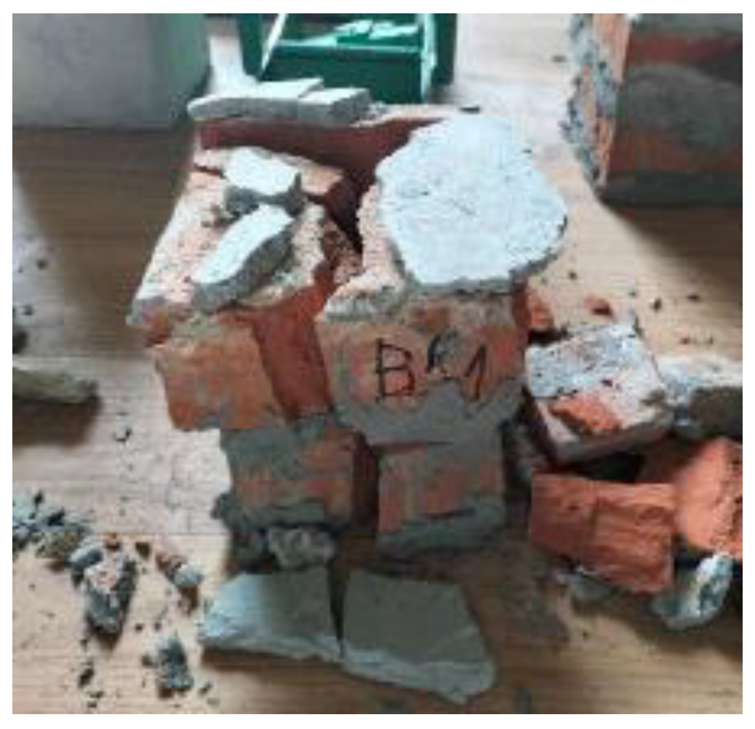
The Evaluation of the Compression Strength
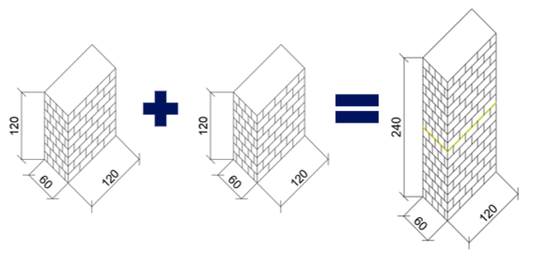
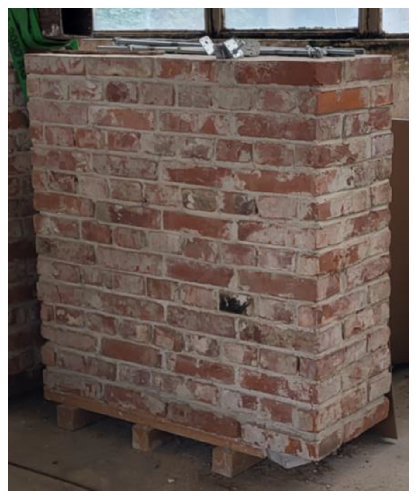
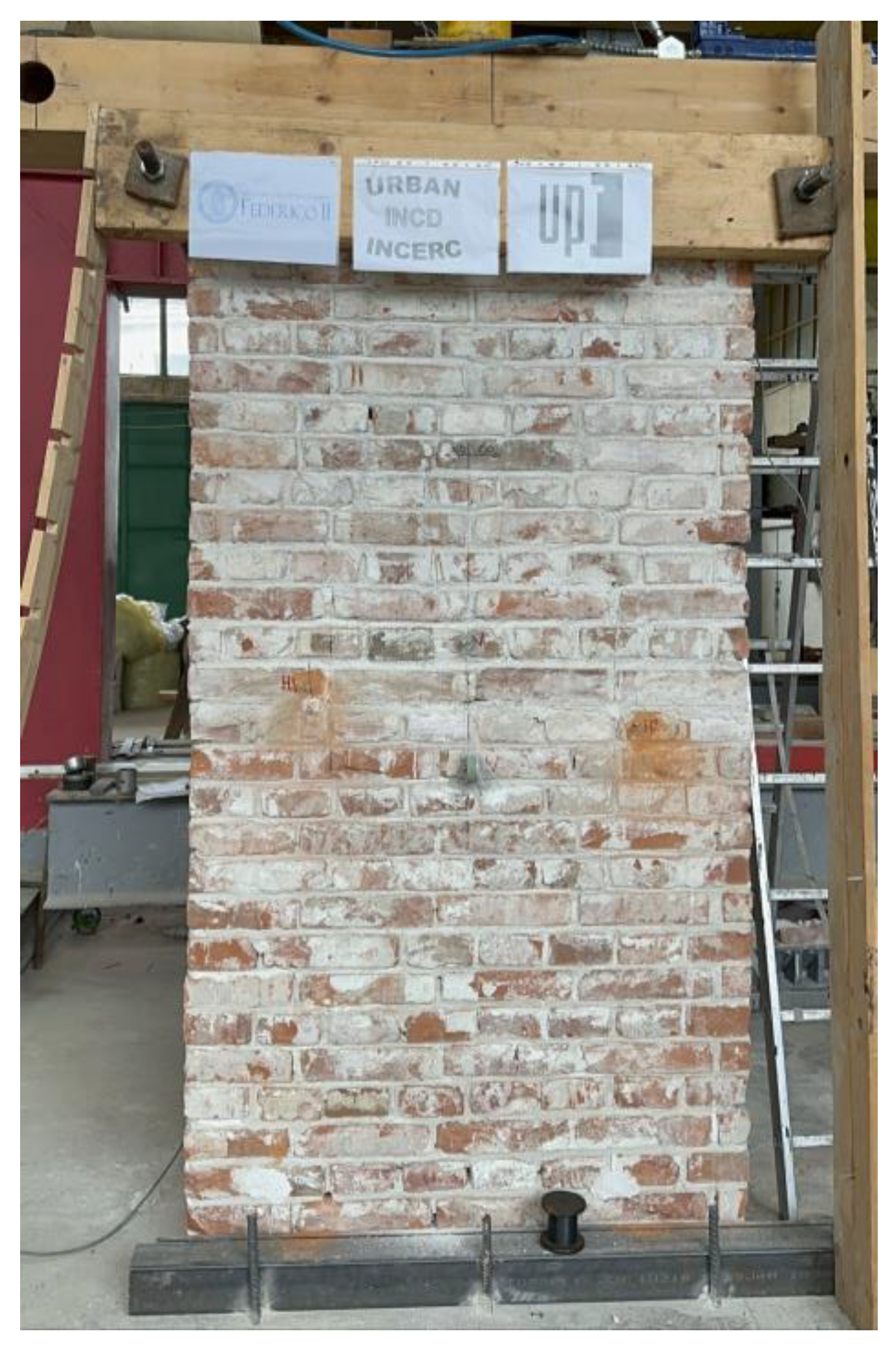
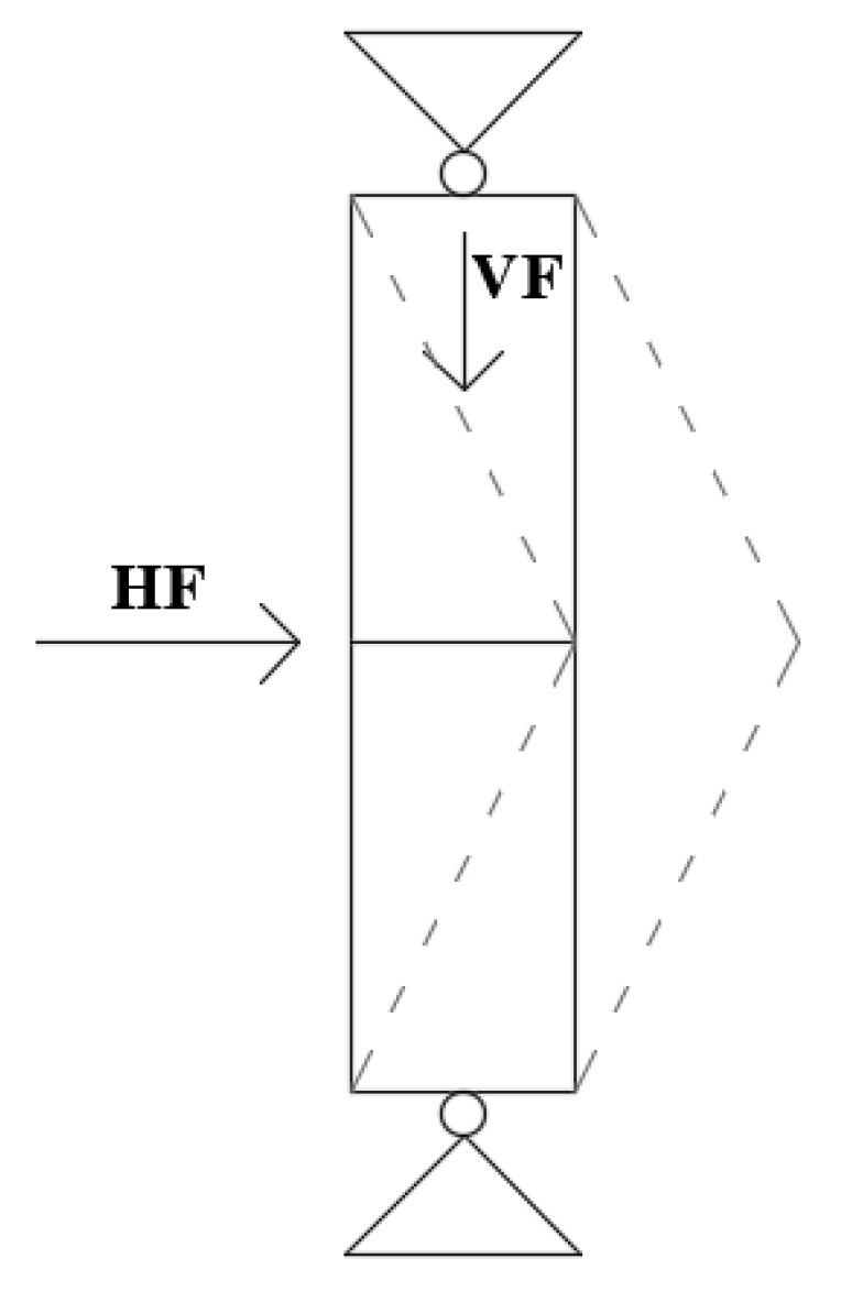
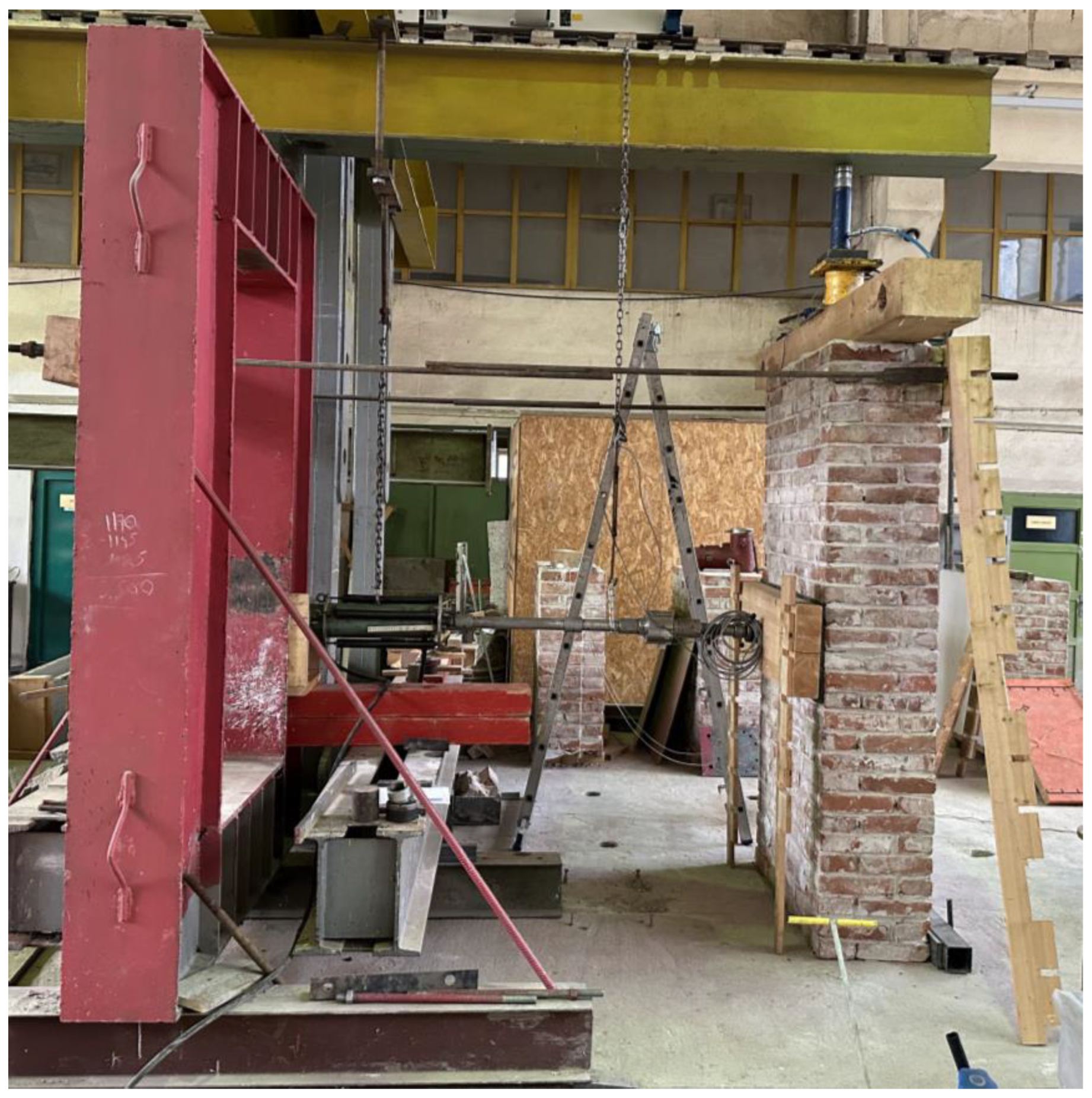
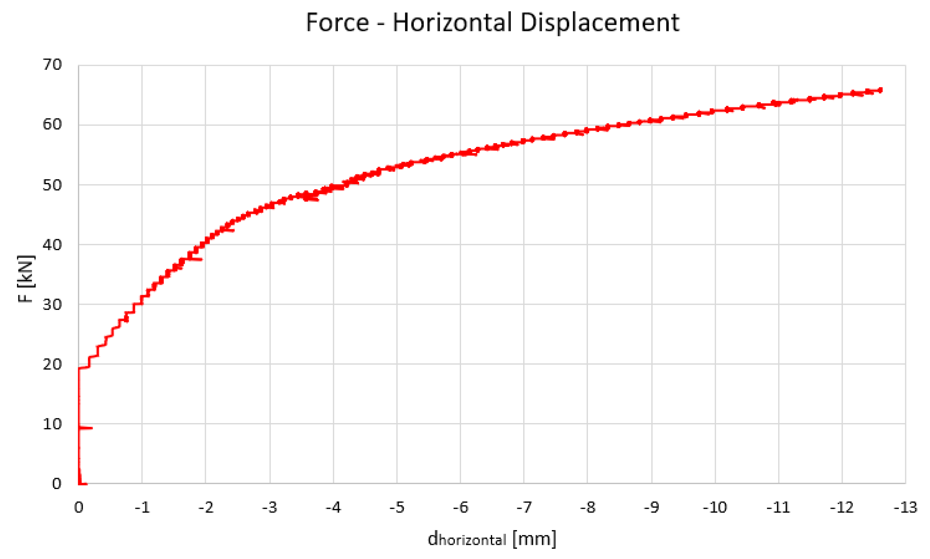
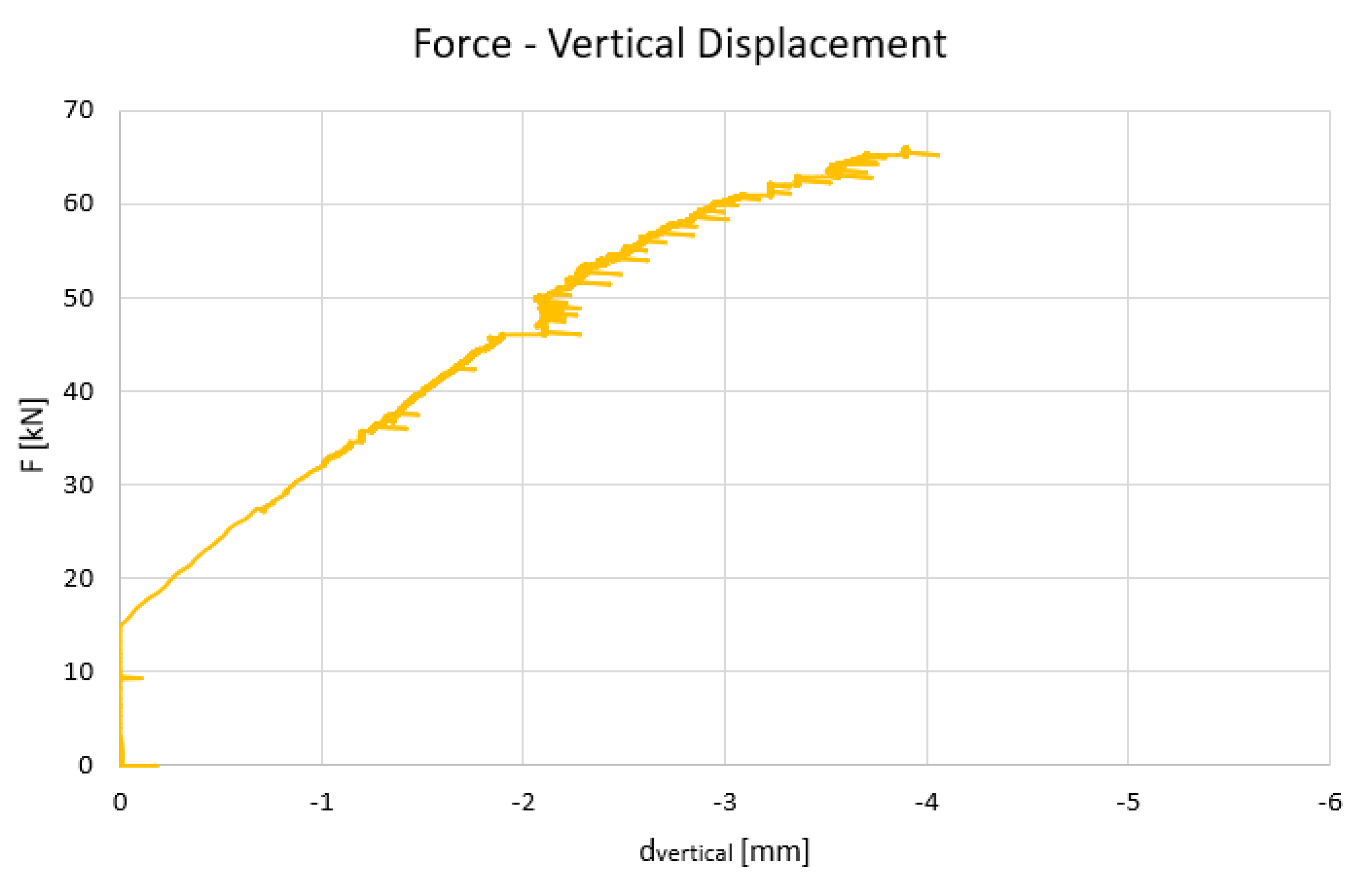
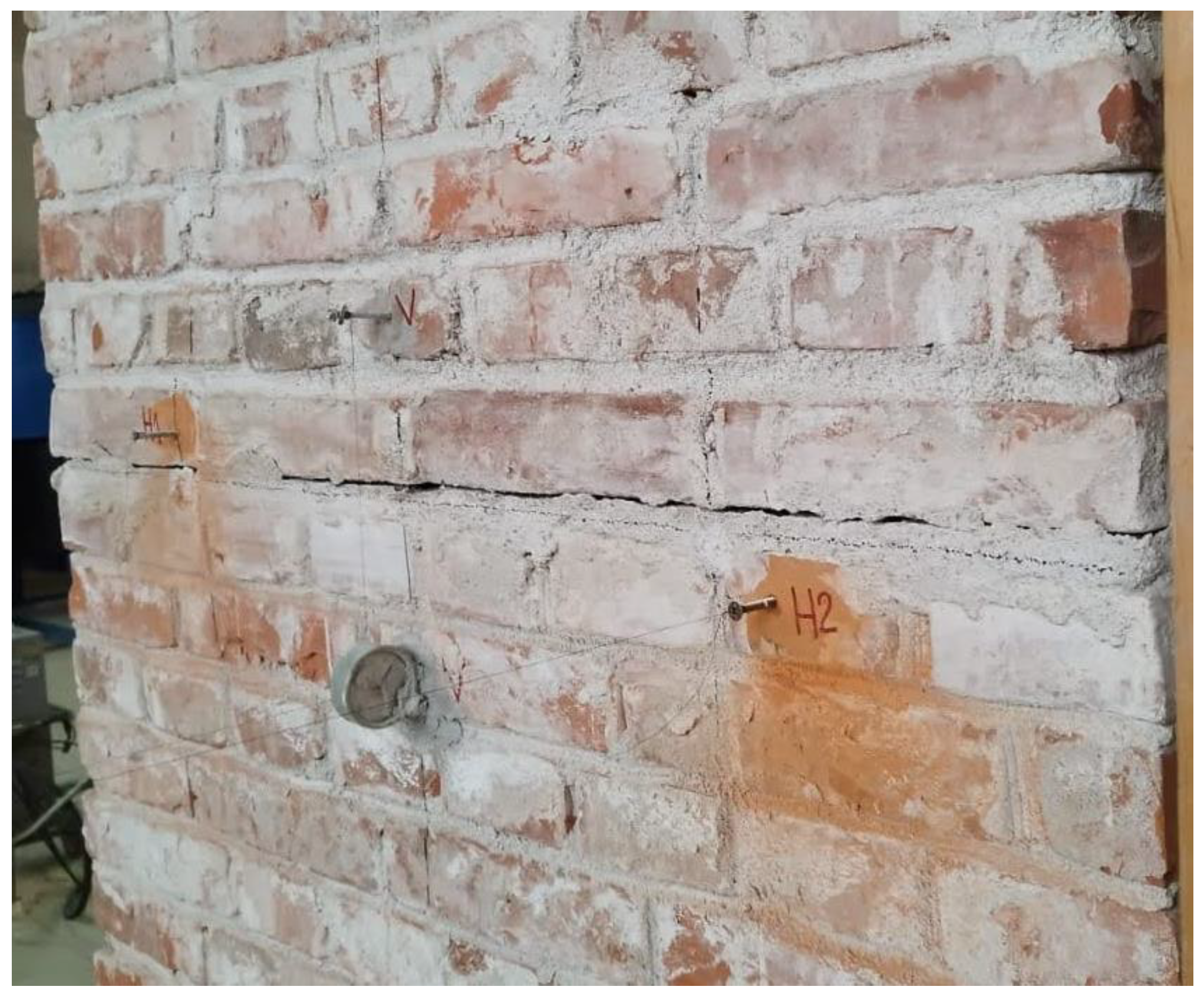
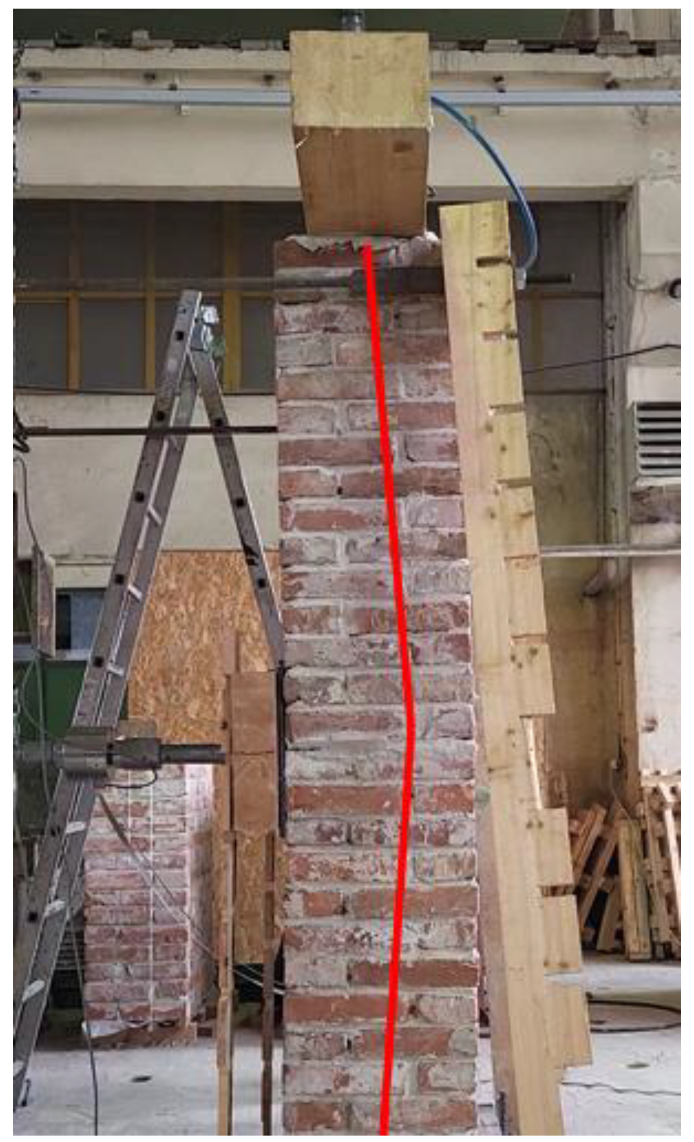
3. Test on the Unreinforced Masonry Wall
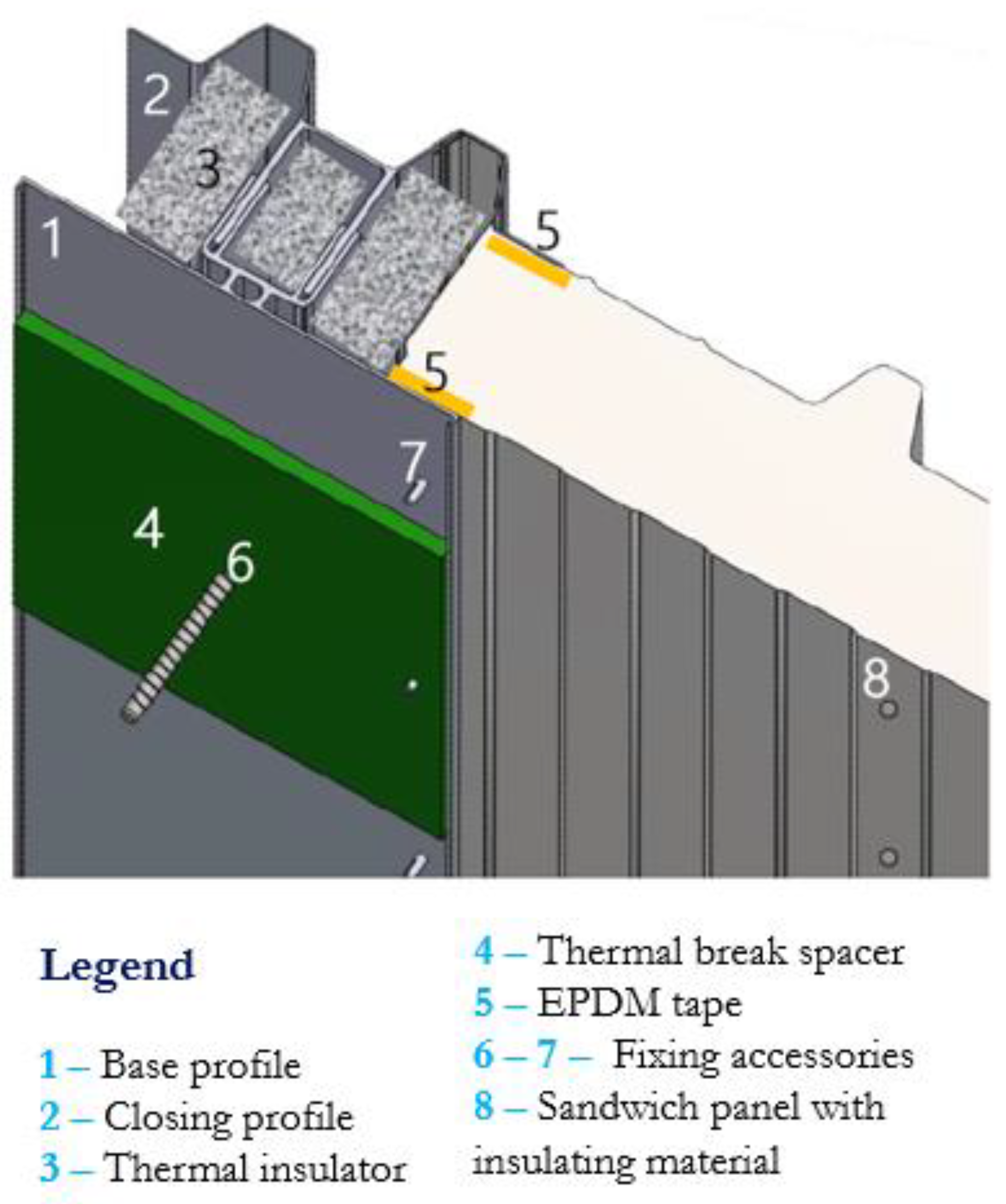
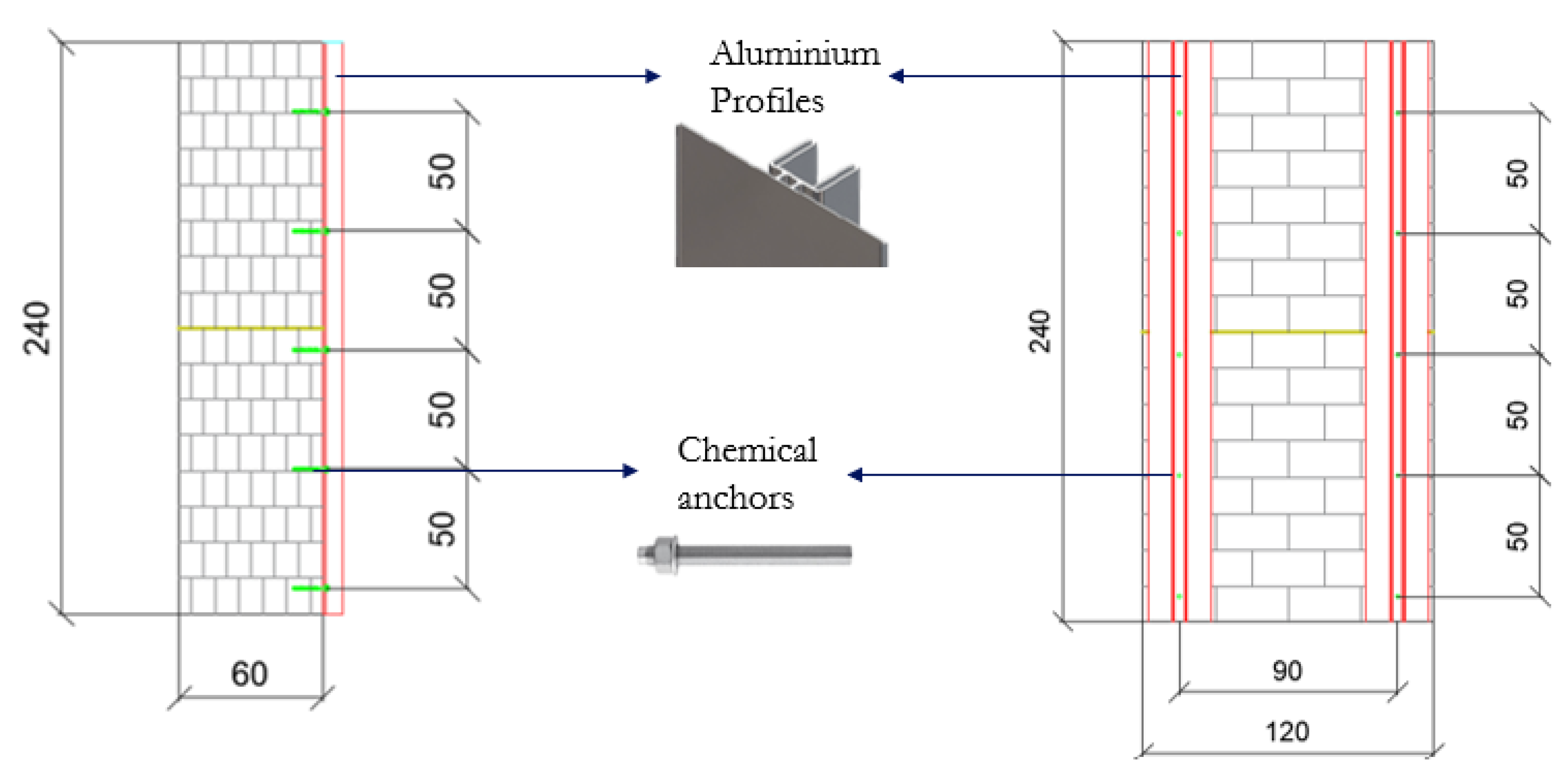
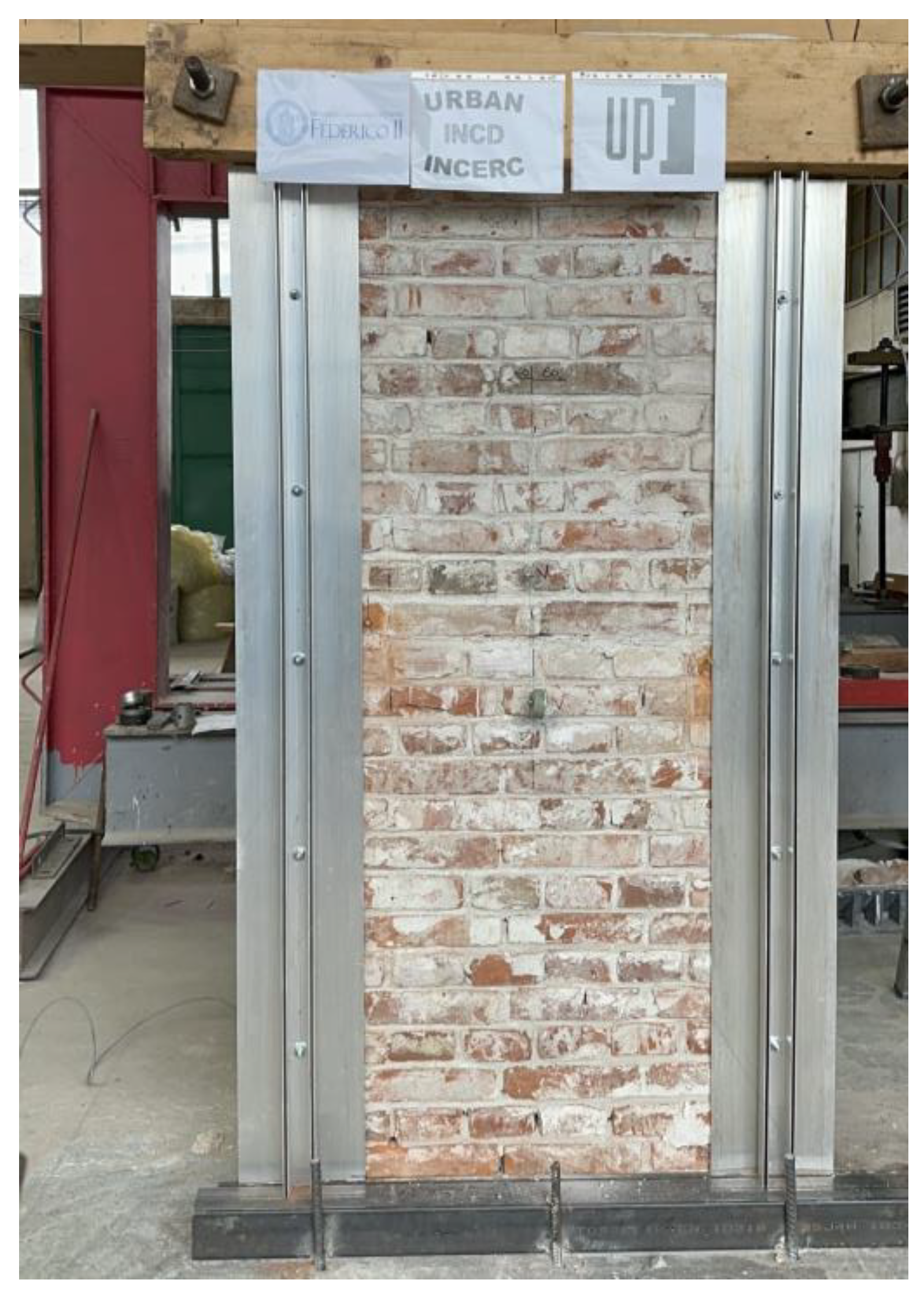
4. The Retrofitting System: The MIL15.s Seismic Energy Coat
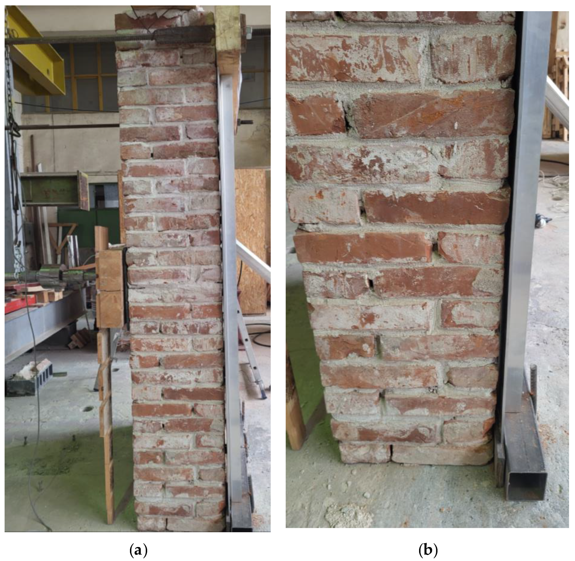
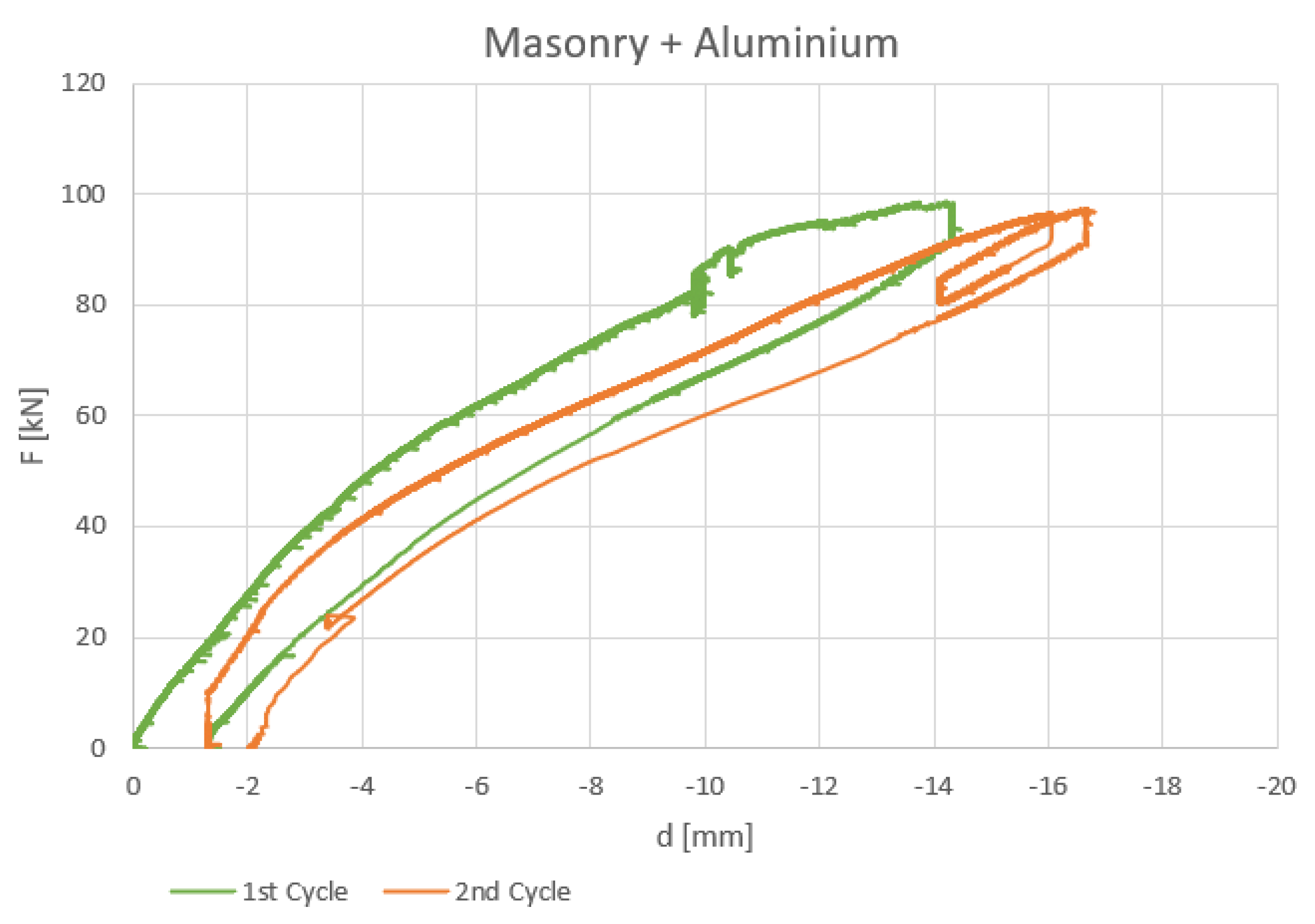
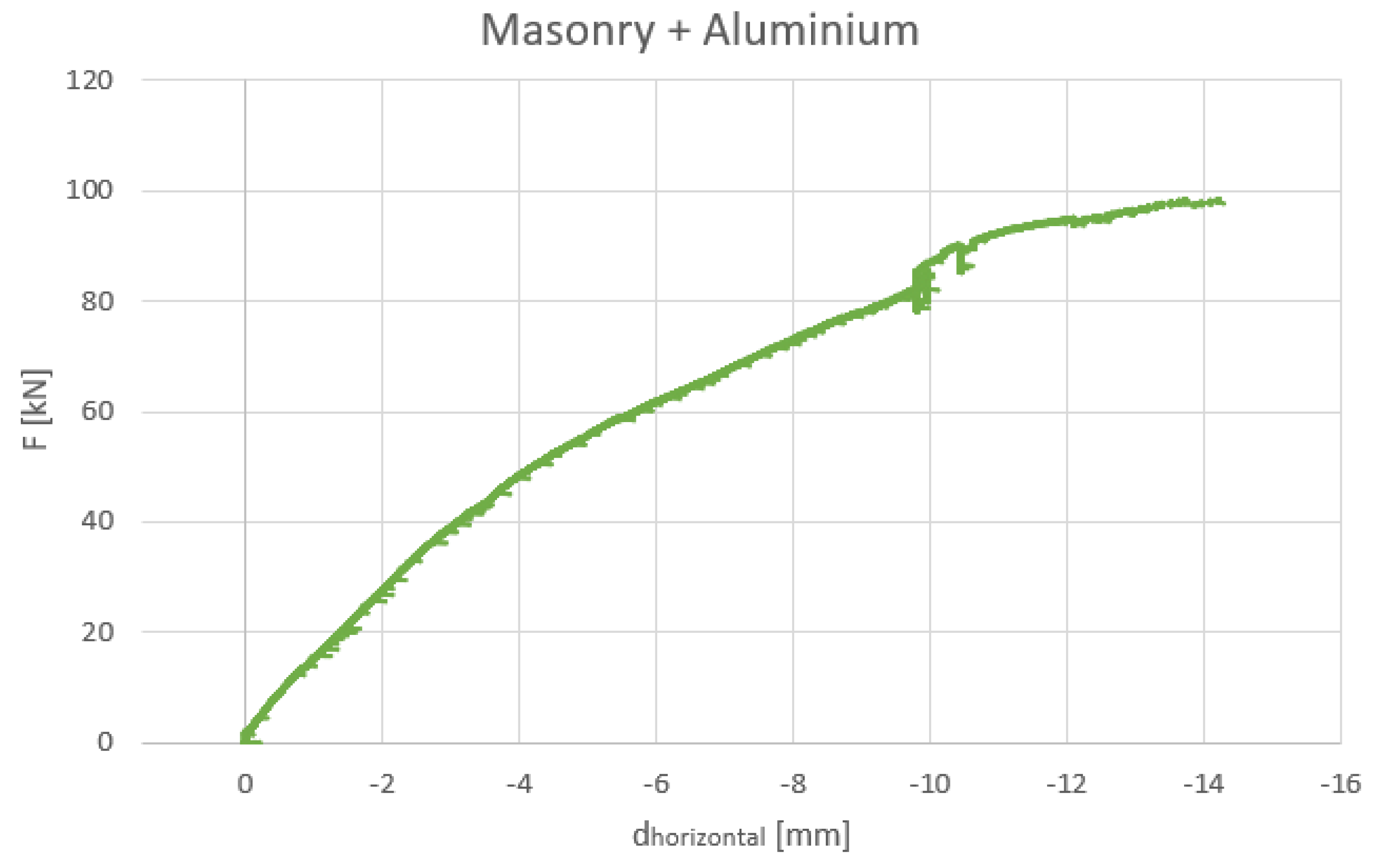
5. Second Part of the Experimental Test: The Consolidated Wall
6. Comparison with the Numerical Simulation
7. Conclusions
Author Contributions
Funding
Institutional Review Board Statement
Informed Consent Statement
Data Availability Statement
Acknowledgments
Conflicts of Interest
References
- Valluzzi, M.R.; Sbrogiò, L.; Saretta, Y. Intervention strategies for the seismic improvement of masonry buildings based on FME validation: The case of a terraced building struck by the 2016 Central Italy earthquake. Buildings 2021, 11, 404. [Google Scholar] [CrossRef]
- Valente, M.; Milani, G.; Grande, E.; Formisano, A. Historical masonry building aggregates: Advanced numerical insight for an effective seismic assessment on two row housing compounds. Eng. Struct. 2019, 190, 360–379. [Google Scholar] [CrossRef]
- Greco, A.; Lombardo, G.; Pantò, B.; Famà, A. Seismic vulnerability of historical masonry aggregate buildings in Oriental Sicily. Int. J. Archit. Herit. 2018, 14, 514–540. [Google Scholar] [CrossRef]
- D’Alpaos, C.; Valluzzi, M.R. Protection on cultural heritage buildings and artistic assets from seismic hazard: A hierarchical approach. Sustainability 2020, 12, 1608. [Google Scholar] [CrossRef]
- Vlachakis, G.; Vlachaki, E.; Lourenco, P.B. Learning from failure: Damage and failure of masonry structures, after the 2017 Lesvos earthquake (Greece). Eng. Fail. Anal. 2020, 117, 104803. [Google Scholar] [CrossRef]
- Mosoarca, M.; Onescu, I.; Onescu, E.; Azap, B.; Chieffo, N.; Szitar-Sirbu, M. Seismic vulnerability assessment for the historical areas of the Timişoara city, Romania. Eng. Fail. Anal. 2019, 101, 86–112. [Google Scholar] [CrossRef]
- Longobardi, G.; Formisano, A. Seismic vulnerability assessment and consolidation techniques of ancient masonry buildings: The case study of a Neapolitan Masseria. Eng. Fail. Anal. 2022, 138, 106306. [Google Scholar] [CrossRef]
- Onescu, E.; Onescu, I.; Moşoarca, M.; Ion, A. Case study of the seismic vulnerability of a historical building in Timişoara, Romania. Proc. IOP Conf. Ser. Mater. Sci. Eng. 2023, 2928, 020004. [Google Scholar]
- D’Altri, A.M.; Sarhosis, V.; Milani, G.; Rots, J.; Cattari, S.; Lagomarsino, S.; Sacco, E.; Tralli, A.; Castellazzi, G.; de Miranda, S. Modeling Strategies for the Computational Analysis of Unreinforced Masonry Structures: Review and Classification. Arch. Comput. Methods Eng. 2020, 27, 1153–1185. [Google Scholar] [CrossRef]
- Grillanda, N.; Valente, M.; Milani, G.; Chiozzi, A.; Tralli, A. Advanced numerical strategies for seismic assessment of historical masonry aggregates. Eng. Struct. 2020, 212, 110441. [Google Scholar] [CrossRef]
- Bocan, D.; Bocan, A.; Keller, A.; Gruin, A. Analysis of thermal rehabilitation and seismic strengthening solutions suitable for heritage structures. Sustainability 2024. submitted. [Google Scholar]
- Pohoryles, D.A.; Bournas, D.A.; Da Porto, F.; Caprino, A.; Santarsiero, G.; Triantafillou, T. Integrated seismic and energy retrofitting of existing buildings: A state-of-the-art review. J. Build. Eng. 2022, 61, 105274. [Google Scholar] [CrossRef]
- Pohoryles, D.A.; Maduta, C.; Bournas, D.A.; Kouris, L.A. Energy performance of existing residential buildings in Europe: A novel approach combining energy with seismic retrofitting. Energy Build. 2020, 223, 110024. [Google Scholar] [CrossRef]
- Heat Roadmap Europe. Heating and Cooling: Facts and Figures; Fraunhofer: Munich, Germany, 2017. [Google Scholar]
- European Parliament, Council of the European Union. Directive (EU) 2018/844 of the European Parliament and of the Council of 30 May 2018 amending Directive 2010/31/EU on the energy performance of buildings and Directive 2012/27/EU on energy efficiency (Text with EEA relevance). OJL 2018, 156, 75–91. [Google Scholar]
- Pertile, V.; De Stefani, L.; Scotta, R. Development and characterization of a system for the seismic and energy retrofit of existing buildings. In Proceedings of the XIV International Conference on Building Pathology and Constructions Repair, Florence, Italy, 20–22 June 2018. [Google Scholar]
- United Nations Environment Programme. Global Status Report for Buildings and Construction: Towards a Zero-Emission, Efficient and Resilient Buildings and Construction Sector; United Nations Environment Programme: Nairobi, Kenya, 2020. [Google Scholar]
- European Commission. The European Green Deal—Communication from the Commission to the European Parliament, the European Council, the Council, the European Economic and Social Committee and the Committee of the Regions; European Commission: Brussels, Belgium, 12 November 2019. [Google Scholar]
- The White House. FACT SHEET: Biden Administration Accelerates Efforts to Create Jobs Making American Buildings More Affordable, Cleaner, and Resilient; The White House: Washington, DC, USA, 17 May 2021.
- Menna, C.; Del Vecchio, C.; Di Ludovico, M.; Mauro, G.M.; Ascione, F.; Prota, A. Conceptual design of integrated seismic and energy retrofit interventions. J. Build. Eng. 2021, 38, 102190. [Google Scholar] [CrossRef]
- Italian Government. Incentives for Building Energy Retrofit (ECO-BONUS); Official Gazette: Rome, Italy, 2020. (In Italian)
- Cao, X.Y.; De-Cheng, F.; Zhun, W.; Gang, W. Parametric investigation of the assembled bolt-connected buckling-restrained brace and performance evaluation of its application into structural retrofit. J. Build. Eng. 2022, 48, 103988. [Google Scholar] [CrossRef]
- Cao, X.Y.; De-Cheng, F.; Chun-Lin, W.; Dejian, S.; Gang, W. A stochastic CSM-based displacement-oriented design strategy for the novel precast SRC-UHPC composite braced-frame in the externally attached seismic retrofitting. Compos. Struct. 2023, 321, 117308. [Google Scholar] [CrossRef]
- Basiricò, T.; Enea, D. Seismic and Energy Retrofit of the Historic Urban Fabric of Enna (Italy). Sustainability 2018, 10, 1138. [Google Scholar] [CrossRef]
- Meglio, E.; Longobardi, G.; Formisano, A. Integrated seismic—Energy retrofit system for preventing failure of a historical RC school building: Comparison among metal lightweight exoskeleton solutions. Eng. Fail. Anal. 2023, 154, 107663. [Google Scholar] [CrossRef]
- Formisano, A. A new seismic coating system for requalification of existing constructions. In Proceedings of the 10th International Conference on Behaviour of Steel Structures in Seismic Areas, Timişoara, Romania, 25–27 May 2022. [Google Scholar]
- Davino, A.; Longobardi, G.; Meglio, E.; Dallari, A.; Formisano, A. Seismic energy upgrading of an existing brick masonry building by a cold—Formed steel envelope system. Buildings 2022, 12, 1918. [Google Scholar] [CrossRef]
- Ecosism. Geniale Cappotto Sismico®. Available online: https://www.ecosism.com/moduli/geniale/ (accessed on 1 March 2024).
- Ecosism. Karma Cappotto Armato®. Available online: https://www.ecosism.com/moduli/karma/ (accessed on 1 March 2024).
- SismaCoat. Available online: https://www.sismacoat.it/ (accessed on 1 March 2024).
- BetonTherm. Available online: https://www.betontherm.com/ (accessed on 1 March 2024).
- Duosystem. Available online: https://duosystem.eu/ (accessed on 1 March 2024).
- Progettosisma. Available online: https://www.progettosisma.it/resisto-cappotto-antisismico (accessed on 1 March 2024).
- EN 1993-1-1:2005; Eurocode 3—Design of the Steel Structures. European Committee for Standardization: Brussels, Belgium, 2005.
- EN 1999-1-1:2003; Eurocode 9—Design of Aluminium Structures. European Committee for Standardization: Brussels, Belgium, 2005.
- Ministerial Circular n.7/2019 (M. C.; 02/01/2019) Instructions for the application of the “Upgrading of Technical Codes for Constructions” (M. D: 17/01/ 2018). Official Gazette of the Italian Republic, 2 January 2019.
- Ministry of Infrastructure and Transport. Technical Standards for Construction; nr. 42 of 20-2-2018; Official Gazette: Rome, Italy, 2018. (In Italian) [Google Scholar]
- TM Group. Available online: https://www.tmgroupsrl.eu/ (accessed on 18 September 2023).
- Longobardi, G.; Formisano, A. Mechanical—Based seismic fragility assessment and retrofit intervention of clustered buildings. In Proceedings of the 9th ECCOMAS Thematic Conference on Computational Methods in Dynamics and Earthquake Engineering, Athens, Grece, 12–14 June 2023. [Google Scholar]
- Bocan, D.; Keller, A.; Moşoarca, M.; Bocan, C. Experimental Investigation of One-Sided strengthening interventions on historic brick masonry walls. In Structural Analysis of Historical Constructions SAHC 2023; Endo, Y., Hanazato, T., Eds.; RILEM Book Series; Springer: Cham, Switzerland, 2023; Volume 47. [Google Scholar] [CrossRef]
- Sun, Y. The use of aluminium alloys in structures: Review and outlook. In Structures; Elsevier: Amsterdam, The Netherlands, 2023; Volume 57, p. 105290. [Google Scholar]
- Mazzolani, F.M. Competing issues for aluminium alloys in structural engineering. Prog. Struct. Eng. Mater. 2004, 6, 185–196. [Google Scholar] [CrossRef]
- Verma, R.P.; Lila, M.K. A short review on aluminium alloys and welding in structural applications. Mater. Today Proc. 2021, 46, 10687–10691. [Google Scholar] [CrossRef]
- Hamdy, A.S.; Doench, I.; Möhwald, H. Intelligent self-healing corrosion resistant vanadia coating for AA2024. Thin Solid Film. 2011, 520, 1668–1678. [Google Scholar] [CrossRef]
- Zhang, K.; Yu, S. Preparation of wear and corrosion resistant micro-arc oxidation coating on 7N01 aluminium alloy. Surf. Coat. Technol. 2020, 388, 125453. [Google Scholar] [CrossRef]
- Cui, J.; Roven, H.J. Recycling of automotive aluminium. Trans. Nonferrous Met. Soc. Chin. 2010, 20, 2057–2063. [Google Scholar] [CrossRef]
- G’andara, M.F. Aluminium: The metal of choice. Mater. Tehnol. 2013, 47, 261–265. [Google Scholar]
- Capuzzi, S.; Timelli, G. Preparation and melting of scrap in aluminium recycling: A review. Metals 2018, 8, 249. [Google Scholar] [CrossRef]
- Sevigné-Itoiz, E.; Gasol, C.M.; Rieradevall, J.; Gabarrell, X. Environmental consequences of recycling aluminium old scrap in a global market. Resour. Conserv. Recycl. 2014, 89, 94–103. [Google Scholar] [CrossRef]
- Ozic, K.; Markic, I.; Moretic, A.; Lulic, L. The Assessment and Retrofitting of Cultural Heritage—A Case Study of a Residential Building in Glina. Buildings 2023, 13, 1798. [Google Scholar] [CrossRef]


| Sample | Side 1 [mm] | Side 2 [mm] | Force [daN] | Compression Resistance [N/mm2] |
|---|---|---|---|---|
| B1 | 148 150 148 | 147 146 138 | 18,080 | 8.47 |
| B2 | 144 143 144 | 146 149 144 | 23,750 | 11.30 |
| B3 | 144 147 141 | 140 139 142 | 19,310 | 9.56 |
| Phase 1—Test on Unreinforced Masonry Wall (1.20 m × 1.20 m × 0.60 m) | ||
|---|---|---|
| Horizontal Displacement [mm] | Vertical Displacement [mm] | Horizontal Force [kN] |
| 1 | 0.02 | 13.67 |
| 2 | 0.64 | 26.81 |
| 3 | 1.19 | 35.14 |
| 4 | 2.11 | 49.86 |
| 5 | 2.27 | 52.94 |
| 6 | 2.53 | 55.13 |
| 7 | 2.71 | 57.47 |
| 8 | 2.88 | 59.26 |
| 9 | 3.08 | 60.85 |
| 10 | 3.36 | 62.42 |
| 11 | 3.51 | 63.53 |
| 12.59 Ultimate Hor. Displ. | 3.89 Ultimate Vert. Displ. | 65.94 |
| Phase 1—Test on Unreinforced Masonry Wall (1.20 m × 2.40 m × 0.60 m) | ||
|---|---|---|
| Horizontal Force [kN] | Horizontal Displacement [mm] | Vertical Displacement [mm] |
| 65.94 | 12.59 | 3.89 |
| Alloy | Characteristic Value of 0.2 Proof Strength f0.2 | Ultimate Tensile Strength fu | Breaking Elongation | Buckling Class | Durability Class |
|---|---|---|---|---|---|
| Al–Si–Mg | 150 MPa | 190 Mpa | 8% | A | B |
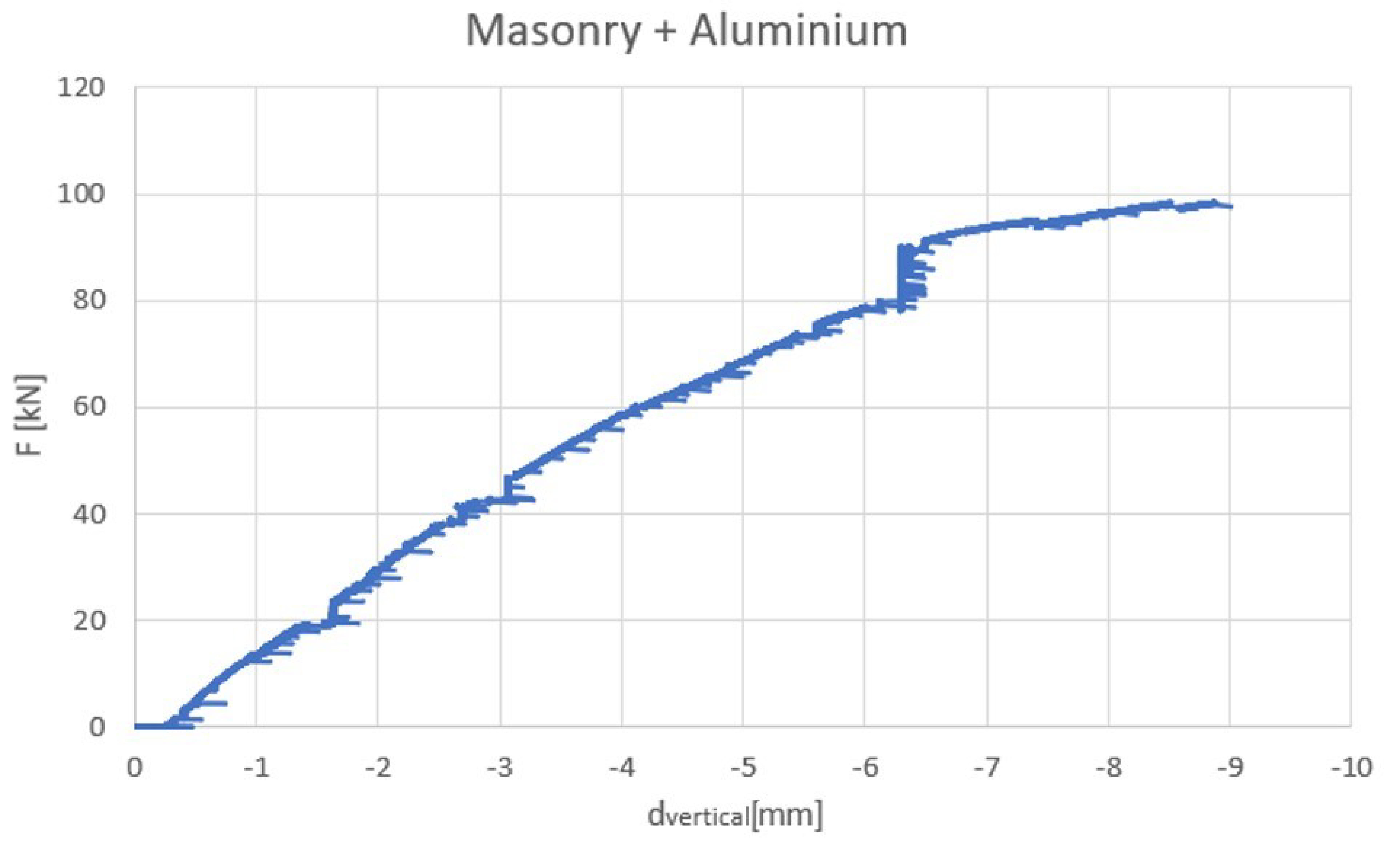
| Phase 2—Test on Reinforced Masonry Wall (1.20 m × 2.40 m × 0.60 m) | ||
|---|---|---|
| Horizontal Displacement [mm] | Vertical Displacement [mm] | Horizontal Force [kN] |
| 1 | 1.11 | 15.38 |
| 2 | 1.93 | 27.68 |
| 3 | 2.59 | 38.88 |
| 4 | 3.22 | 48.42 |
| 5 | 3.77 | 55.74 |
| 6 | 4.33 | 61.77 |
| 7 | 4.87 | 67.31 |
| 8 | 5.40 | 72.90 |
| 9 | 5.94 | 78.15 |
| 10 | 6.29 | 87.05 |
| 11 | 6.68 | 92.36 |
| 12 | 7.33 | 94.81 |
| 13 | 8.02 | 96.47 |
| 14.20 | 8.89 | 98.32 |
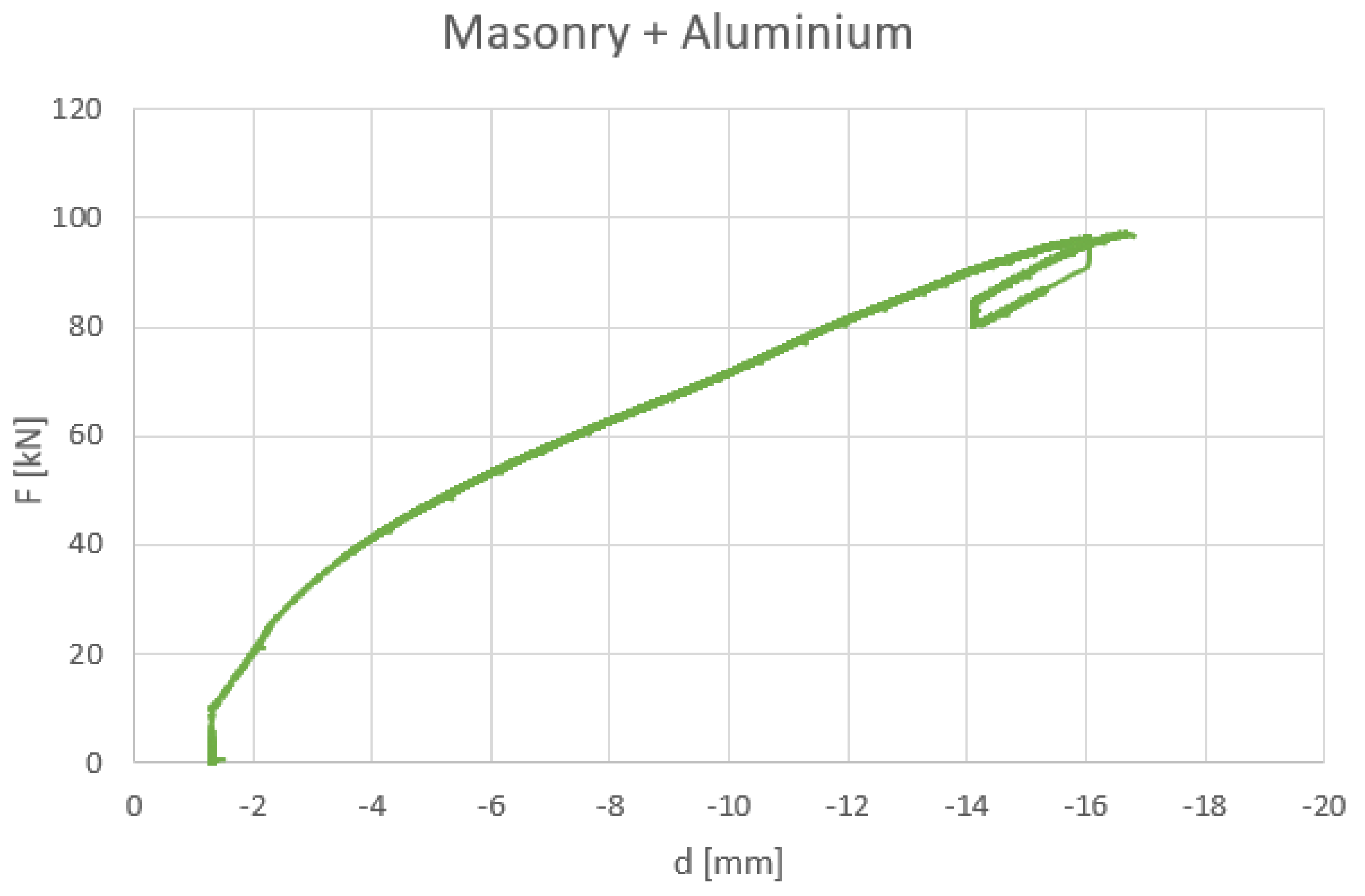
| Phase 2—Test on Reinforced Masonry Wall (1.20 m × 1.20 m × 0.60 m) | ||
|---|---|---|
| Horizontal Displacement [mm] | Vertical Displacement [mm] | Horizontal Force [kN] |
| 1.30 | 2.07 | 10.17 |
| 2 | 2.24 | 20.20 |
| 3 | 2.77 | 33.01 |
| 4 | 3.29 | 41.24 |
| 5 | 3.85 | 47.58 |
| 6 | 4.39 | 53.23 |
| 7 | 5.00 | 58.12 |
| 8 | 5.66 | 62.75 |
| 9 | 6.27 | 67.10 |
| 10 | 6.89 | 71.60 |
| 11 | 7.50 | 76.56 |
| 12 | 8.12 | 81.37 |
| 13 | 8.79 | 85.63 |
| 14 | 9.50 | 90.04 |
| 15 | 10.15 | 93.45 |
| 16.66 | 11.39 | 97.08 |
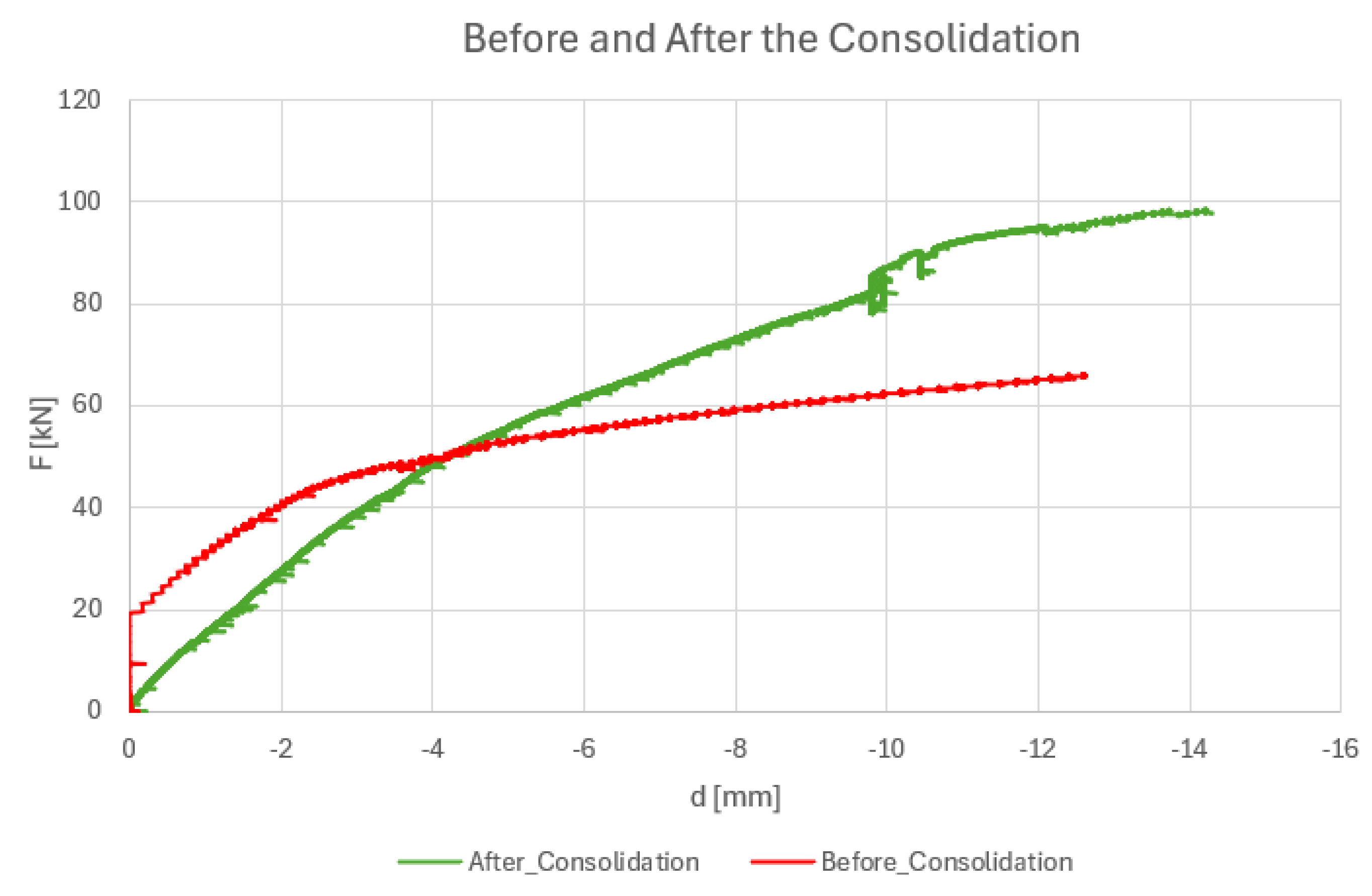
| Phase 1—Test on Unreinforced Masonry Wall (1.20 m × 2.40 m × 0.60 m) | ||
|---|---|---|
| Horizontal Force [kN] | Horizontal Displacement [mm] | Vertical Displacement [mm] |
| 65.94 | 12.59 | 3.89 |
| Phase 2—Test on Reinforced Masonry Wall (1.20 m × 2.40 m × 0.60 m) | ||
| Horizontal Force [kN] | Horizontal Displacement [mm] | Vertical Displacement [mm] |
| 98.32 | 14.20 | 8.89 |
| Horizontal Force [kN] | Horizontal Displacement [mm] |
|---|---|
| 66.5 | 14.2 |
| Horizontal Force [kN] | Horizontal Displacement [mm] |
|---|---|
| 88.8 | 17.3 |
| 1st Phase—Unconsolidated Masonry Panel—Experimental Test | 1st Phase—Consolidated Masonry Panel—Numerical Simulation |
|---|---|
| Horizontal Force [kN] | Horizontal Force [kN] |
| 65.94 | 66.5 |
| Horizontal Displacement [mm] | Horizontal Displacement [mm] |
| 12.59 | 14.2 |
| 2nd Phase—Consolidated Masonry Panel—Experimental Test | 2nd Phase—Consolidated Masonry Panel—Numerical Simulation |
| Horizontal Force [kN] | Horizontal Force [kN] |
| 98.32 | 88.8 |
| Horizontal Displacement [mm] | Horizontal Displacement [mm] |
| 14.20 | 17.3 |
Disclaimer/Publisher’s Note: The statements, opinions and data contained in all publications are solely those of the individual author(s) and contributor(s) and not of MDPI and/or the editor(s). MDPI and/or the editor(s) disclaim responsibility for any injury to people or property resulting from any ideas, methods, instructions or products referred to in the content. |
© 2024 by the authors. Licensee MDPI, Basel, Switzerland. This article is an open access article distributed under the terms and conditions of the Creative Commons Attribution (CC BY) license (https://creativecommons.org/licenses/by/4.0/).
Share and Cite
Longobardi, G.; Moşoarca, M.; Gruin, A.; Ion, A.; Formisano, A. An Innovative, Lightweight, and Sustainable Solution for the Integrated Seismic Energy Retrofit of Existing Masonry Structures. Sustainability 2024, 16, 4791. https://doi.org/10.3390/su16114791
Longobardi G, Moşoarca M, Gruin A, Ion A, Formisano A. An Innovative, Lightweight, and Sustainable Solution for the Integrated Seismic Energy Retrofit of Existing Masonry Structures. Sustainability. 2024; 16(11):4791. https://doi.org/10.3390/su16114791
Chicago/Turabian StyleLongobardi, Giovanna, Marius Moşoarca, Aurelian Gruin, Alexandru Ion, and Antonio Formisano. 2024. "An Innovative, Lightweight, and Sustainable Solution for the Integrated Seismic Energy Retrofit of Existing Masonry Structures" Sustainability 16, no. 11: 4791. https://doi.org/10.3390/su16114791
APA StyleLongobardi, G., Moşoarca, M., Gruin, A., Ion, A., & Formisano, A. (2024). An Innovative, Lightweight, and Sustainable Solution for the Integrated Seismic Energy Retrofit of Existing Masonry Structures. Sustainability, 16(11), 4791. https://doi.org/10.3390/su16114791