Abstract
In this paper, a novel central air-conditioning system with an internal heat exchanger is proposed and analyzed for its energy-saving effect. Two frequently used systems are chosen as the reference systems, i.e., a conventional system with a sensible heat exchanger (Reference System I) and a conventional system with a total heat exchanger (Reference System II). Analysis models are built to simulate the performance of the system. The energy-saving effects of the proposed system and the two reference systems under different conditions are theoretically calculated using a case-studied shopping mall in Nanjing, China. The results show that the influence of indoor relative humidity (RH) on the energy-saving effect is much greater than that of the indoor design temperature. Indoor design parameters have a greater impact on energy saving than outdoor design parameters. Under the studied conditions, the maximum energy-saving rates of the proposed system, Reference System I, and Reference System II, are 52.7%, 2.3%, and 12.1%, respectively. With the decrease in fresh-air ratio from 70% to 20%, the difference in energy-saving rates between the proposed system and Reference System II (Reference System I) can increase from 5% to 23% (15% to 30%). Therefore, the proposed system has obvious energy-saving potential and advantage, especially under the condition of a lower fresh-air ratio.
1. Introduction
1.1. Background
With the development of society, an increasing number of high-grade buildings have been built in the world [1]. Central air conditioning has become increasingly important and has been widely used in emerging buildings because it can create a good indoor environment, which helps to improve human life quality or work efficiency [2,3,4]. However, the central air-conditioning system is one of the most energy-consuming building services and takes up about 40% of the total building power consumption during peak load periods [5,6]. In particular, the COVID-19 pandemic in recent years required the fresh-air ratio of the central air-conditioning system to be increased (even up to 100%) in order to manage the spread of the virus, which led to higher consumed energy [7]. The International Energy Agency predicts that the number of air-conditioning units will reach 5.6 billion (3.5 times the current amount) by 2050 and that the increased energy consumption will be very large [1]. Compared to the split-type air conditioner, the central air-conditioning system continuously operates throughout the year, and accordingly, it consumes much more energy [1]. Therefore, the energy-saving qualities of the central air-conditioning system are important and should be a focus of study.
1.2. Literature Review
Air-conditioning systems are mainly used to control the temperature and humidity of indoor air [8]. In a conventional central air-conditioning system, the chilled water (at 7 °C) from central chillers is widely used to cool and dehumidify the indoor air [8,9]. The cooled air at low temperatures cannot be supplied to the room directly because the feeling of cold wind is uncomfortable for people [10]. It should be reheated to the required air supply state by the external energy, which leads to lower energy performance in a conventional central air-conditioning system [9]. The cooling and reheating energy consumed in central air-conditioning systems has a great potential to be saved through some new technologies. For instance, liquid-desiccant dehumidification technology has received growing interest in recent years [11] because it does not require a low-temperature cooling source to dehumidify the air and then avoid the following reheating process [9]. Concurrently, various energy-recovery devices have been employed to save energy in central air-conditioning systems. The exhaust air can pre-cool the entered fresh air through the energy-recovery facility [12]. In addition, optimization operation control is also an effective method of energy saving in central air-conditioning systems, and this has been studied by researchers [13].
The liquid-desiccant air-conditioning (LDAC) systems have the advantages of high efficiency and energy saving [9]. Guan et al. [9] proposed a novel hybrid LDAC system in which the liquid dehumidifier and regenerator were cascaded, and the regeneration process was creatively moved indoors. Compared to the conventional vapor compression air-conditioning (VCR) system, the electric power saving rate of the proposed system could achieve 30.7% under typical summer conditions in Guangzhou, China, owing to the saving of reheating energy. Pandelidis et al. [14] proposed a novel multi-stage LDAC system combining the Mai-sotsenko Cycle and the desiccant wheel. The analysis results show that the multi-stage desiccant system was able to absorb higher latent heat loads and had a higher coefficient of performance (COP) than the conventional system. Kabeel et al. [15] used desiccant cycles to separately control the humidity and temperature of moist air in an efficient, moist-free air-conditioning system. The experimental results showed that the COP of the system was 48.2% higher than the conventional VCR system. Liang et al. [16] proposed an LDAC system using CaCl2 solution as a desiccant. The developed system was combined with shallow geothermal energy to achieve the goal of energy savings. The calculated results revealed that it could save 86% power consumption compared to the conventional VCR system. Chen et al. [17] built a thermodynamics model to analyze the performance of an LDAC system combined with CO2 transcritical cycles. Owing to the increase in evaporation temperature (from 7 °C to 12 °C) in the novel system, compression work of the CO2 transcritical cycle could be greatly reduced, even up to 26.3%. Li et al. [18] presented a solar LDAC system and numerically studied its performance to assess the feasibility of energy saving. Simulation results showed that the efficiency could be improved by 25–50% (compared with the VCR system) under weather conditions observed in Hong Kong. An energy-efficient heat exchanger was added to the conventional LDAC system, and water was used as a working fluid to replace the air in the liquid-desiccant regenerator by Naik et al. [19]. Then, they developed a thermal model to evaluate the performance of the new system and compared it with that of the conventional LDAC system. They found that the novel system could obtain higher efficiency by 20.8%.
With respect to the application of energy-recovery devices in air-conditioning systems, Yang et al. [20] tested the actual performance of an energy-efficient air-conditioning system with a low-temperature regenerative periodic total heat exchanger in an office located at the Taipei Water Department. They found that applying the proposed system to handle the incoming air could save 13–19% of the energy consumption during a year-round operation. Chang et al. [21] installed energy-storing materials in the periodic total heat exchanger to replace the original rotary energy wheels to improve its operation performance in air-conditioning systems. The ameliorative periodic total heat exchanger was experimentally investigated, and the results indicated it could save more energy in motors. Li et al. [22] combined an indirect evaporative cooler (IEC) with a sensible heat exchanger (SHE) and energy-recovery exchanger (ERE) to design two two-stage modified heat recovery systems applied as an exhaust air heat recovery component. The numerical analysis showed that the two developed systems could, respectively, increase the heat transfer capacity by 47.6% and 48.5%, compared to the stand-alone IEC under typical summer conditions.
The existing problems of extensive management and invalid operation in the central air-conditioning system are one of the main energy waste behaviors. Therefore, it is important to find out and correct the unreasonable conditions during the operation of the air-conditioning system. For this purpose, Jing et al. [23] established an energy-saving diagnosis model to provide a reference for the operation of the air-conditioning system. The case study data indicated that the problem moments of the air-conditioning operation could be diagnosed. Concurrently, the energy-saving rate increased to 11.9%. Eremkin et al. [24] proposed a combination of a displacement ventilation and air-conditioning system and a “bottom-up” ventilation scheme. The results show that this scheme improves the system’s efficiency, and the maximum energy consumption can be reduced by up to 45%. Yu et al. [13] proposed a new type of air-conditioning control scheme for university classroom buildings, and then the contrastive analysis between the new scheme and the original scheme was studied by TRNSYS 17 software. The simulation results showed that the energy-saving rate of the new control scheme could reach 15.27%. Asad et al. [25] developed a distributed real-time optimal control for typical centralized air-conditioning systems. The proposed scheme broke the centralized problem into one primary problem and several sub-problems, which could be independently solved in parallel. Numerical analysis demonstrated that the distributed real-time optimal control scheme could achieve a 4.48%, 10.85%, and 6.45% reduction of energy use in spring, summer, and autumn, respectively, compared with the benchmark case.
1.3. Scope and Contribution
According to the above literature review, the VCR unit is the most widely used central air-conditioning system in our daily lives. The installation of energy-recovery devices is an effective way to improve the efficiency of conventional VCR systems. However, it can be found that most of the studies on energy-recovery devices mainly focus on exhaust air heat recovery. Energy-recovery devices with internal heat exchangers have not been seen in the scope of the studied literature. Therefore, this paper proposes a new energy-saving air-conditioning system using an internal heat exchanger, and a two-story high-grade shopping mall building with an area of 14,256 m2 in Nanjing, China, is chosen as a case study for our analysis. Based on the first law of thermodynamics, the maximum energy-saving potential of the proposed new energy-efficient air-conditioning system is theoretically analyzed, and the optimum efficiency of the internal heat exchanger at different indoor and outdoor parameters is investigated when the proposed system has the maximum energy savings. On this basis, the influence of indoor and outdoor parameters on the energy efficiency of the proposed system is explored from the point of view of the energy-saving amount and energy-saving rate compared with the conventional VCR system. The existing literature focuses only on conventional VCR systems with sensible heat exchangers and conventional VCR systems with total heat exchangers. Therefore, this paper discusses the effect of indoor and outdoor parameters and fresh-air ratio on the energy efficiency of the three systems. Finally, the energy-saving potential and advantages of the new system are obtained by comparison. In the future, the new energy-saving air-conditioning system proposed in this paper can be involved in the energy management of the active distribution network of office buildings [26].
2. System Description
In this paper, a two-story high-grade shopping mall (with the same structure on both floors) in Nanjing is selected for the case study. The single-story area of the building is 99 m × 72 m, the floor height is 5.1 m, and the air-conditioned area is about 6900 m2 per floor. Based on this building, an in-house computational code is developed in this paper to perform an energy-saving retrofit design for the proposed novel energy-saving air-conditioning system, with the detailed parameters shown in Table 1 and Table 2.

Table 1.
Envelope properties.
Table 2.
Input values for internal loads.
Considering the counteraction between the reheat and cooling energy in the process of supplying air, the conventional VCR system must be optimized to improve efficiency. Figure 1a shows the schematic of the studied system, in which an internal heat exchanger is added to recover energy. The corresponding air-conditioning process of the system is shown in Figure 1b. The different state points represent different air conditions, which can be described as follows: W and N are the outdoor air state and the indoor air state, respectively; C is the mixing state point of the fresh air and return air; C1 is the state point of the mixed air pre-cooled by the internal heat exchanger; O is the state point of supply air; L is the state point of apparatus dewpoint; Ф is the relative humidity line; ε is the condition line (hot-moisture ratio line). In a conventional central air-conditioning system, the mixed air needs to be handled from point C to point L and then reheated to supply air state O. However, in the new system, the heat transfer processes of “C–C1” and “L–O” take place in the internal heat exchanger, which means that no external energy (including heating and cooling energy) is consumed. The chilled water needs to handle the air from state C1 to state L. Hence, the energy saved by the proposed system includes two parts: the reheating energy (progress of “L–O”) and the cooling energy difference between the progress of “C–L” and “C1–L”.
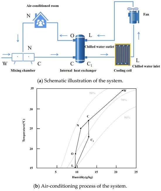
Figure 1.
The schematic and air-conditioning process of the central air-conditioning system with internal heat exchanger (tid/tod: 25 °C/34.8 °C, RHid/RHod: 55%/61%).
3. Analysis of the Energy Consumption of Air-Conditioning Process
To demonstrate the energy-saving advantage of the proposed system, which is compared with not only the conventional system but also two other frequently used energy-efficient systems, respectively, using the sensible and total heat exchanger. Figure 2a and Figure 3a show the schematic of the two energy-saving systems, respectively. Figure 2b and Figure 3b show the air-conditioning processes of the two energy-efficient systems, respectively. In the following study of the paper, the VCR system using the sensible and total heat exchanger is marked as Reference System I and Reference System II, respectively.
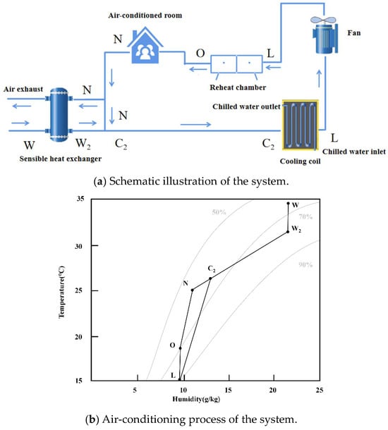
Figure 2.
The schematic and air-conditioning process of the Reference System I (tid/tod: 25 °C/34.8 °C, RHid/RHod: 55%/61%).
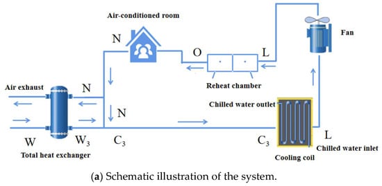
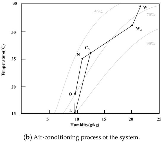
Figure 3.
The schematic and air-conditioning process of the Reference System II (tid/tod: 25 °C/34.8 °C, RHid/RHod: 55%/61%).
In Figure 2, state point W2 represents the condition of the fresh air pre-cooled by the sensible heat exchanger. State points W and W2 have the same specific humidity because only sensible heat transfer occurs in the sensible heat exchanger. C2 is the mixing state point of the return air and fresh air pre-cooled by the sensible heat exchanger. Analogously, state points W3 and C3 in Figure 3 represent corresponding air conditions.
(1) Calculation of the heat exchange efficiencies
For the internal heat exchanger (see Figure 1):
where η1 is the efficiency of the internal heat exchanger, dimensionless; to, tL, tc, tC1 are the temperatures of air at state point O, L, C, and C1, respectively, °C.
For the sensible heat exchanger (see Figure 2):
where tW, tN, tW2 are the temperatures of air at state points W, N, and W2, respectively, °C.
For the total heat exchanger (see Figure 3):
where hW, hN, hW2 are the specific enthalpy of air at state points W, N, and W2, respectively, kJ·kg−1.
(2) Calculation of the energy consumption
For the conventional central air-conditioning system, the energy consumption includes:
(i) the cooling energy provided by the chilled water:
where QC is the cooling energy provided by the chilled water, kW; MS is the mass flow of supply air, kg·s−1; hC and hL are the specific enthalpy of air at state point C and L, respectively, kJ·kg−1.
(ii) the reheating energy:
where Qre is the reheating energy, kW; ho is the specific enthalpy of supply air, kJ·kg−1.
For the new central air-conditioning system, the energy consumption includes:
where QC1 is the cooling energy provided by the chilled water, kW; hC1 is the specific enthalpy of air at state point C1, kJ·kg−1.
For the Reference System I, the energy consumption includes:
(i) the cooling energy provided by the chilled water:
where QC2 is the cooling energy provided by the chilled water, kW; hC2 is the specific enthalpy of air at state point C2, kJ·kg−1.
(ii) the reheating energy of Reference System I is equal to that of a conventional system.
For the Reference System II, the energy consumption includes:
(i) the cooling energy provided by the chilled water:
where QC3 is the cooling energy provided by the chilled water, kW; hC3 is the specific enthalpy of air at state point C3, kJ·kg−1.
(ii) the reheating energy of Reference System II is equal to that of a conventional system.
According to the above analysis on the energy consumption of the air-conditioning process, compared to the conventional central air-conditioning system, the energy-saving effects of the new system, Reference System I and Reference System II can be obtained as follows:
The amount of energy saving:
For the new system:
For the Reference System I:
For the Reference System II:
The rate of energy saving:
For the new system:
For the Reference System I:
For the Reference System II:
4. Results and Discussion
In the paper, the energy-saving effects of the new system, Reference System I and Reference System II, are calculated and compared in detail under various conditions based on a two-story high-grade shopping mall building with an area of 14,256 m2 in Nanjing, China. Figure 4 shows the monthly average outdoor temperature and RH in Nanjing throughout the year. Reviewing and summarizing the research conclusions of many scholars on thermal comfort [27,28,29,30,31], the design temperature and RH ranges of the indoor/outdoor air are determined to be 23–28 °C/32–37 °C and 40–65%/55–80% in this study. The temperature difference of supply air is assumed to be 6 °C. The typical summer condition in the Nanjing area (i.e., the temperature and RH are 34.8 °C and 61%, respectively) is used for the outdoor design state parameter at various indoor states. When the outdoor conditions change, the indoor temperature and RH are set to 25 °C and 55%, respectively. The minimum fresh-air volume depends on the number of people in the room of the shopping mall building. According to the design state parameters of indoor/outdoor air and the Chinese standards GB 50189-2015 [32] and GB 50736-2012 [33], the cooling and humidity loads can be calculated for determining the supply air state point O. Finally, the amounts and rates of energy saving in the new system, the Reference System I and the Reference System II are obtained accordingly. The details of the calculative process are shown in Figure 5 and Figure 6.
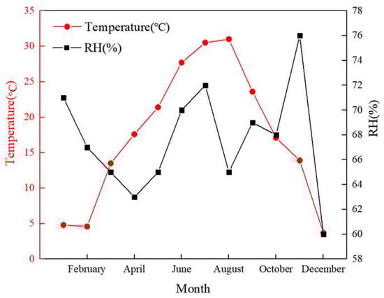
Figure 4.
The monthly average outdoor temperature and relative humidity in Nanjing throughout the year.
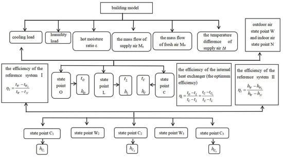
Figure 5.
Flow chart for calculating parameters of each state point.
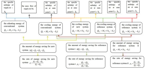
Figure 6.
Flow chart of calculating the energy-saving amount and energy-saving rate.
The efficiency directly affects the heat transfer capacity between the hot and cold fluids in the internal heat exchanger. The main aim of this new system is to save reheating energy. According to the requirement, the air at the state of apparatus dewpoint L should be heated to supply air state O in the internal heat exchanger (see Figure 1). Both over-heating and under-heating cannot meet the aforementioned demand. Therefore, the required heat transfer efficiency corresponding to the air-conditioning process of “L–O” is defined as the optimum efficiency of the internal heat exchanger in this paper. Figure 7 shows the optimum efficiency of the internal heat exchanger with various indoor design temperatures and RH under typical summer conditions in the Nanjing area. It can be found that the optimum efficiency of the internal heat exchanger increases with the increase of indoor design temperature and the decrease of indoor design RH. Under the studied conditions, it is obvious that the maximum efficiency of the internal heat exchanger is less than 0.58, which is not difficult to achieve in a present heat exchanger. Figure 8 shows the optimum efficiency of the internal heat exchanger with various outdoor design temperatures and RH. It can be seen that the optimum efficiency of the internal heat exchanger decreases with the increase in outdoor design temperature. However, the difference between the maximum and the minimum efficiency of the internal heat exchanger is approximately 0.03, which indicates that outdoor design temperature has little influence on the optimum efficiency of the internal heat exchanger. Moreover, the optimum efficiency of the internal heat exchanger is independent of the RH when the RH exceeds 55% under the studied conditions.
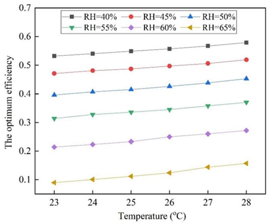
Figure 7.
The optimum efficiency of internal heat exchanger with various indoor states (tod: 34.8 °C, RHod: 61%).
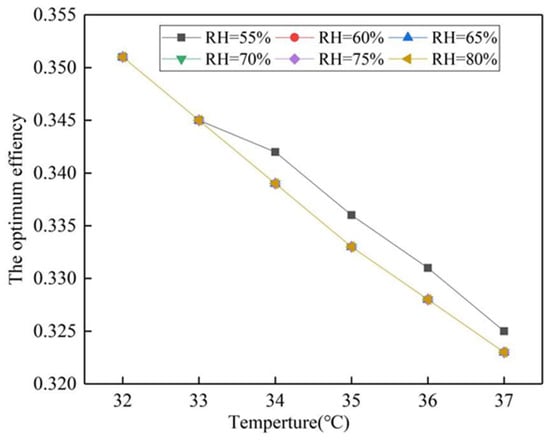
Figure 8.
The optimum efficiency of internal heat exchanger with various outdoor states (tid: 25 °C, RHid: 55%).
During the operation of a conventional central air-conditioning system, reheating is one of the main sources of energy consumption. Concurrently, the same amount of cooling energy originally used in the cooling process of the supply air is offset and wasted. Therefore, the amount of reheating energy can directly reveal the energy-saving potential of the new system proposed in the paper. Figure 9 delineates the influence on the reheating energy of various indoor design parameters under typical summer conditions in the Nanjing area. As can be seen from Figure 9, an increase in indoor design RH can obviously lead to a decrease in reheating energy. In addition, the influence of indoor design temperature on the reheat energy is much less than that of indoor design RH. This phenomenon indicates that the proposed new system will demonstrate an increasing number of energy-saving advantages over the conventional system with a decrease in the indoor design RH. The reheating energy of the system is the same under various outdoor conditions due to the constant state points of supply air and apparatus dewpoint.
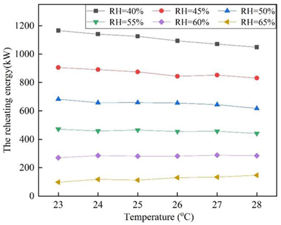
Figure 9.
The reheating energy with various indoor states in the conventional system (tod: 34.8 °C, RHod: 61%).
Figure 10 shows the energy-saving amount of the new system with various indoor design parameters. The amount of energy saving obviously increases with the decrease of indoor design RH, and the influence of indoor design RH on the amount of energy saving is much greater than that of indoor design temperature. For instance, the energy-saving amount rises from 196.306 kW to 2332.51 kW when the indoor design RH is from 65% to 40% and the indoor design temperature is 23 °C. When the indoor design temperature is from 23 °C to 28 °C and the indoor design RH is 65%, the energy-saving amount rises from 196.306 kW to 294.206 kW. Therefore, the energy-saving amount varies between 196.306 kW and 2332.51 kW with the change in indoor design parameters. Compared to the conventional system, the energy saved by the new system includes two parts: the reheating energy and the same amount of cooling energy offset by the reheating energy. According to the law of energy conservation, the new system can save twice as much energy as the reheating energy of the conventional system. Therefore, the variation trend of the energy-saving amount is basically the same as that of reheating energy with the change in indoor design temperature and RH. The energy-saving amount of the studied new system with various outdoor design parameters is constant.
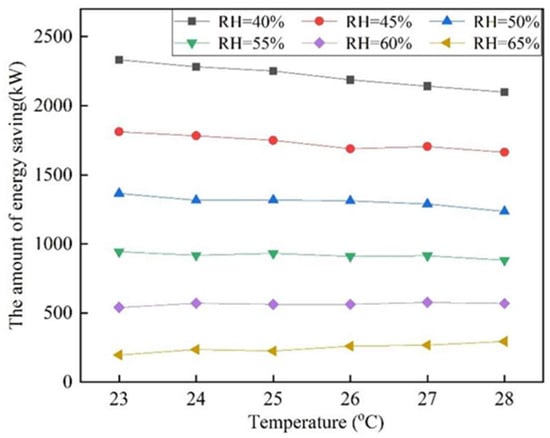
Figure 10.
The amount of energy saving of the new system with various indoor states (tod: 34.8 °C, RHod: 61%).
Figure 11 depicts the effect of the indoor design temperature and RH on the energy-saving rate of the proposed new system. It can be found that the increase in the design temperature and the decrease in the design RH can promote the energy-saving rate. However, the influence of RH is much greater than that of temperature. For instance, the energy-saving rate rises from 9.07% to 51.92% when the indoor design RH is from 65% to 40% and the indoor design temperature is 23 °C. When the indoor design temperature is from 23 °C to 28 °C and the indoor design RH is 65%, the energy-saving rate rises from 9.07% to 16.04%. Therefore, the energy-saving rate varies between 9.07% and 52.74% with the change in indoor design parameters.
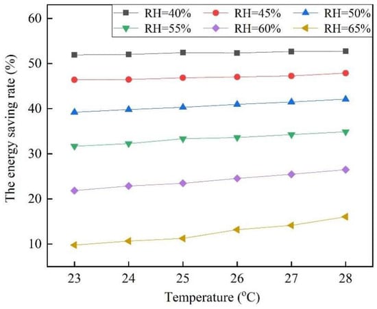
Figure 11.
The energy-saving rate of the new system with various indoor states (tod: 34.8 °C, RHod: 61%).
Figure 12 describes the effect of the outdoor design temperature and RH on the energy-saving rate of the proposed new system. The trend of the energy-saving rate under different outdoor design temperatures is opposite to that under different indoor temperatures, and the energy-saving rate increases with the decrease of outdoor design RH. This is because the reheating energy of the new system does not vary with the outdoor design temperature and RH, but the total energy consumption of the air-conditioning system increases due to the increase of outdoor design temperature and RH. Therefore, the energy-saving rate of the new system decreases with the increase in outdoor design temperature and RH. This indicates that the energy efficiency of the proposed new system will be improved with the decrease in the outdoor design RH and temperature.
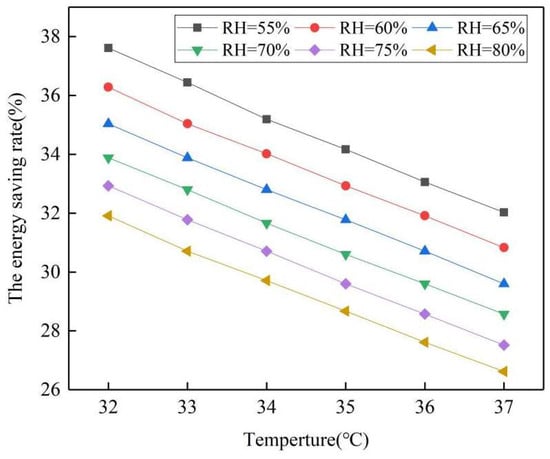
Figure 12.
The energy-saving rate of the new system with various outdoor states (tid: 25 °C, RHid: 55%).
In the paper, two reference systems are chosen to compare the energy-saving effect with the proposed new system. During the calculation, the heat exchanger efficiencies of the three heat exchangers (i.e., the internal heat exchanger, the sensible heat exchanger, and the total heat exchanger) are kept the same as a benchmark of comparison. The energy-saving amounts and rates of the three systems with various indoor states are shown in Figure 13 and Figure 14, respectively. As is obvious, the energy-saving effect of the new system is much higher than that of the two reference systems. The difference in energy-saving effect between the new system and the reference systems increases rapidly with the decrease of indoor design RH. For the maximum amount of energy saving under the study conditions, the new system can reach 2098.7 kW, which is many times the number of reference systems (in particular, Reference System I), as shown in Figure 13. Correspondingly, the maximum energy-saving rate of the new system is up to 52.7% when the indoor design temperature and relative humidity are 28 °C and 40%, respectively. However, under the same condition, the values of the two reference systems are only 12.1% and 2.3%, as shown in Figure 14.
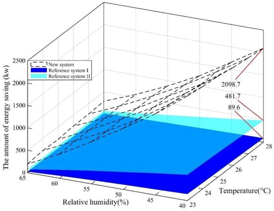
Figure 13.
The amounts of energy saving of three systems with various indoor states (tod: 34.8 °C, RHod: 61%).
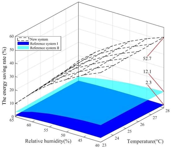
Figure 14.
The energy-saving rates of three systems with various indoor states (tod: 34.8 °C, RHod: 61%).
Figure 15 and Figure 16 show the energy-saving amounts and rates of the three systems with various outdoor states, respectively. Similarly, the energy-saving effect of the new system is much higher than that of the two reference systems. The difference in energy efficiency increases with the decrease in outdoor design temperature between the proposed system and the two reference systems. For instance, when the outdoor design RH is 55%, and the outdoor design temperature is from 32 °C to 37 °C, the energy-saving amounts of the proposed system are 16.4 to 10.4 times higher than that of the Reference System I; and 5.6 to 3.2 times higher than that of the Reference System II, as shown in Figure 15. Under the studied conditions, the maximum energy-saving rate of the new system is up to 37.6% when the outdoor design temperature and RH are 32 °C and 55%, respectively. By contrast, the values of the other two systems are only 6.7% and 2.3% under the same condition, which is shown in Figure 16.
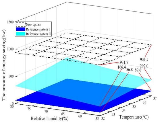
Figure 15.
The amounts of energy saving of three systems with various outdoor states (tid: 25 °C, RHid: 55%).
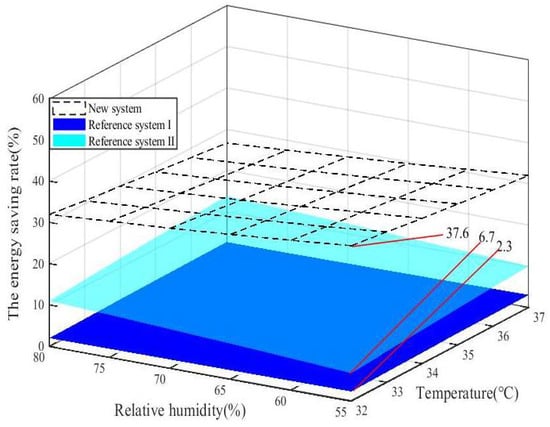
Figure 16.
The energy-saving rates of three systems with various outdoor states (tid: 25 °C, RHid: 55%).
In the new system, the internal heat exchanger can handle all the supply air while the sensible heat exchanger and total heat exchanger can only pre-cool the fresh air. Therefore, the fresh-air volume is one of the main factors affecting the energy-saving effect of the three studied systems. In the above study, the minimum fresh-air volume (the fresh-air ratio is about 20%) based on the number of people in the room is adopted, which leads to the obvious difference in the energy-saving effect between the new system and the two reference systems. With the improvement in the living standards of ordinary people and the COVID-19 pandemic, the fresh-air ratio of the central air-conditioning system is recommended to be increased, and recirculated air is even required to be avoided in enclosed areas [34]. Predictably, an increase in the fresh-air ratio can narrow the difference in the energy-saving effect of the three studied systems. Figure 17 and Figure 18, respectively, illustrate the energy-saving amounts and rates of the three systems with various fresh-air ratios under specific design conditions shown in Table 3.
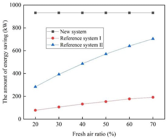
Figure 17.
The energy-saving amounts of three systems with various fresh-air ratios.
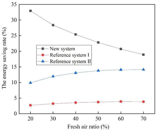
Figure 18.
The energy-saving rates of three systems with various fresh-air ratios.
Table 3.
The specific design condition.
From Figure 17, it is clear that an increase in the fresh-air ratio can effectively increase the energy-saving amount of the two reference systems (in particular, Reference System II). During the calculation, the mass flow of supply air and the state parameter of each point is kept constant, which results in the constant value of the energy-saving amount in the new system. It is universally acknowledged that the increase in fresh-air ratio can lead to a higher cooling load of the central air-conditioning system. Therefore, the energy-saving rate of the new system continues to decline with the increase in the fresh-air ratio. Even so, the new system still has obvious energy-saving advantages compared to reference systems. As can be seen from Figure 18, the difference in energy-saving rates between the new system and Reference System II (Reference System I) ranges from 5% to 23% (15% to 30%), with a decrease in fresh-air ratio from 70% to 20%. This means that when the minimum fresh-air volume is satisfied in the building, the reduction of the fresh-air ratio can significantly improve the energy efficiency of the new system. Compared to the two reference systems, it is obvious that the new system has greater energy-saving potential.
5. Conclusions
In this study, a novel central air-conditioning system with an internal heat exchanger is proposed, and its energy efficiency is analyzed in detail. Two frequently used systems are chosen as the reference systems, i.e., a conventional system with a sensible heat exchanger (marked as Reference System I) and a conventional system with a total heat exchanger (marked as Reference System II). The energy-saving effect of the proposed novel system is compared with that of the two reference systems based on a selected building for evaluating the advantage. The main conclusions are as follows:
- (1)
- The proposed system can save twice as much energy as the reheating energy of the conventional system.
- (2)
- The influence of indoor design RH on the energy-saving effect is much greater than that of the indoor design temperature. The lower the indoor design RH, the more energy is saved.
- (3)
- Indoor design parameters have a greater impact on energy saving than outdoor design parameters.
- (4)
- Under the studied conditions, the maximum energy-saving rate of the new system can be up to 52.7%, while those of the two reference systems are 2.3% (Reference System I) and 12.1% (Reference System II), respectively.
- (5)
- With the decrease of the fresh-air ratio from 70% to 20%, the difference in energy-saving rates between the proposed system and Reference System II (Reference System I) can increase from 5% to 23% (15% to 30%).
- (6)
- The energy efficiency of the proposed system is investigated only in a shopping mall in Nanjing, China, while the specific performance of the proposed system for other types of buildings and other climatic zones will be investigated in future studies.
Author Contributions
Conceptualization, S.D. and D.W.; Methodology, S.D. and D.W.; Formal Analysis, D.W. and K.Z.; Investigation, S.D. and D.W.; Data Curation, K.Z. and M.L.; Writing—Original Draft Preparation, D.W. and Y.L.; Writing—Review and Editing, S.D. and K.Z.; Visualization, K.Z.; Supervision, D.W. and K.Z.; Project Administration, D.W. All authors have read and agreed to the published version of the manuscript.
Funding
This research was funded by the Key University Science Research Project of Anhui Province, grant number KJ2017A055.
Institutional Review Board Statement
Not applicable.
Data Availability Statement
Data are contained within the article.
Acknowledgments
The authors would like to acknowledge the continuous support offered by Anhui MBO Intelligent Technology Co., Ltd. for this research. The research presented in this article also has been conducted by Key University Science Research Project of Anhui Province (KJ2017A055).
Conflicts of Interest
The authors declare no conflicts of interest.
Nomenclature
| h | specific enthalpy of air at state point (kJ·kg−1) |
| M | the mass flow (kg·s−1) |
| Q | cooling energy (kW) |
| t | temperature (°C) |
| Greek Symbols | |
| ε | condition line (hot-moisture ratio line) |
| ρ | the rate of energy saving (%) |
| η | the efficiency of heat exchanger |
| Φ | the relative humidity line |
| Subscripts | |
| C, C1, C2, C3, L, N, O, W, W2, W3 | state point |
| 1 | the new system |
| 2 | Reference System I |
| 3 | Reference System II |
| id | indoor design |
| re | reheating |
| s | supply air |
| od | indoor design |
| Acronyms | |
| COP | coefficient of performance |
| ERE | energy-recovery exchanger |
| IEC | indirect evaporative cooler |
| LDAC | liquid-desiccant air-conditioning |
| RH | relative humidity (%) |
| SHE | sensible heat exchanger |
| VCR | vapor compression air conditioning |
References
- Zhang, Z.J.; Zhang, Y.F.; Khan, A. Thermal comfort of people in a super high-rise building with central air-conditioning system in the hot-humid area of China. Energy Build. 2020, 209, 109727. [Google Scholar] [CrossRef]
- Wang, F.J.; Lee, M.C.; Chang, T.B.; Chen, Y.S.; Jung, R.C. Improving indoor air quality and thermal comfort by total heat exchanger for an office building in hot and humid climate. HVAC&R Res. 2014, 20, 731–737. [Google Scholar] [CrossRef]
- Lv, Y.; Hu, G.Y.; Liang, J.Y.; Chen, X.; Chen, B.; Zhao, T.K.; Lu, X.Y.; Wang, B.; Yuan, W.J.; Li, Y.M. Study on microwave sterilization technology of humidifier in central air conditioning system. Build. Environ. 2019, 160, 106220. [Google Scholar] [CrossRef]
- Chang, C.C.; Chen, S.L.; Lin, T.Y.; Chiang, Y.C. Experimental and theoretical investigation of regenerative total heat exchanger with periodic flow for air-conditioning systems. Int. J. Refrig. 2017, 81, 123–133. [Google Scholar] [CrossRef]
- Liu, L.R.; Gu, J.J.; Liu, J. Analysis of operational energy intensity for central air conditioning systems with water-cooled chiller by decomposition method. Energy Build. 2015, 93, 154–159. [Google Scholar] [CrossRef]
- Xie, K.; Hui, H.X.; Ding, Y.; Song, Y.H.; Ye, C.J.; Zheng, W.D.; Ye, X.Q. Modeling and control of central air conditionings for providing regulation services for power systems. Appl. Energy 2022, 315, 119035. [Google Scholar] [CrossRef]
- Hegazi, A.A.; Abdelrehim, O.; Khater, A. Parametric optimization of earth-air heat exchangers (EAHEs) for central air conditioning. Int. J. Refrig. 2021, 129, 278–289. [Google Scholar] [CrossRef]
- Evron, Y.; Gommed, K.; Grossman, G. Efficient deep dehumidification hybrid air conditioning system. Int. J. Refrig. 2019, 105, 50–58. [Google Scholar] [CrossRef]
- Guan, B.W.; Liu, X.H.; Zhang, T. Investigation of a compact hybrid liquid-desiccant air-conditioning system for return air dehumidification. Build. Environ. 2021, 187, 107420. [Google Scholar] [CrossRef]
- Wan, J.W.; Zhang, J.L.; Zhang, W.M. The effect of heat-pipe air-handling coil on energy consumption in central air-conditioning system. Energy Build. 2007, 39, 1035–1040. [Google Scholar] [CrossRef]
- Song, X.; Zhang, L.; Zhang, X.S. NTU m-based optimization of heat or heat pump driven liquid desiccant dehumidification systems regenerated by fresh air or return air. Energy 2018, 158, 269–280. [Google Scholar] [CrossRef]
- Wang, Y.; Zhao, F.Y.; Kuckelkorn, J.; Liu, D.; Liu, L.Q.; Pan, X.C. Cooling energy efficiency and classroom air environment of a school building operated by the heat recovery air conditioning unit. Energy 2014, 64, 991–1001. [Google Scholar] [CrossRef]
- Yu, K.Z.; Cao, Z.Y.; Liu, Y.L. Research on the optimization control of the central air-conditioning system in university classroom buildings based on TRNSYS software. Procedia Eng. 2017, 205, 1564–1569. [Google Scholar] [CrossRef]
- Pandelidis, D.; Pacak, A.; Cichoń, A.; Anisimova, S.; Drąg, P.; Vager, B.; Vasilijev, V. Multi-stage desiccant cooling system for moderate climate. Energy Convers. Manag. 2018, 177, 77–90. [Google Scholar] [CrossRef]
- Kabeel, A.E.; Bassuoni, M.M. Energy efficient moist free air conditioning system integrated with total heat desiccant solution system. Int. J. Refrig. 2019, 100, 220–226. [Google Scholar] [CrossRef]
- Liang, J.D.; Huang, B.H.; Chiang, Y.C.; Chen, S.L. Experimental investigation of a liquid desiccant dehumidification system integrated with shallow geothermal energy. Energy 2020, 191, 116452. [Google Scholar] [CrossRef]
- Chen, X.Y.; He, Y.J.; Wang, Y.; Chen, G.M. Analysis of a hybrid system of liquid desiccant and CO2 transcritical cycles. Int. J. Refrig. 2019, 105, 101–108. [Google Scholar] [CrossRef]
- Li, Y.T.; Yang, H.X. Investigation on solar desiccant dehumidification process for energy conservation of central air-conditioning systems. Appl. Therm. Eng. 2008, 28, 1118–1126. [Google Scholar] [CrossRef]
- Naik, B.K.; Muthukumar, P. Parametric and performance investigations on novel multipurpose liquid desiccant drying/desalination system. Heat. Transf. Eng. 2021, 42, 1142–1158. [Google Scholar] [CrossRef]
- Yang, C.M.; Chen, C.C.; Chen, S.L. Energy-efficient air conditioning system with combination of radiant cooling and periodic total heat exchanger. Energy 2013, 59, 467–477. [Google Scholar] [CrossRef]
- Chang, C.C.; Liang, J.D.; Chen, S.L. Performance investigation of regenerative total heat exchanger with periodic flow. Appl. Therm. Eng. 2018, 130, 1319–1327. [Google Scholar] [CrossRef]
- Li, W.Y.; Li, Y.C.; Shi, W.X.; Lu, J. Energy and exergy study on indirect evaporative cooler used in exhaust air heat recovery. Energy 2021, 235, 121319. [Google Scholar] [CrossRef]
- Jing, W.Q.; Yu, J.Q.; Luo, W.; Li, C.J.; Liu, X.Y. Energy-saving diagnosis model of central air-conditioning refrigeration system in large shopping mall. Energy Rep. 2021, 7, 4035–4046. [Google Scholar] [CrossRef]
- Eremkin, A.I.; Ponomareva, I.K. System of maintaining parameters of air conditioning in orthodox cathedrals. J. Phys. Conf. Ser. 2021, 1926, 012025. [Google Scholar] [CrossRef]
- Asad, H.S.; Wan, H.; Kasun, H.; Rehan, S.; Huang, G.S. Distributed real-time optimal control of central air-conditioning systems. Energy Build. 2022, 256, 111756. [Google Scholar] [CrossRef]
- Li, Z.N.; Su, S.; Jin, X.L.; Xia, M.C.; Chen, Q.F.; Yamashita, K.J. Stochastic and distributed optimal energy management of active distribution network with integrated office buildings. CSEE J. Power Energy 2022, 10, 504–517. [Google Scholar] [CrossRef]
- Hwang, R.L.; Cheng, M.J. Field survey on human thermal comfort reports in air–conditioned offices in Taiwan. Open Constr. Build. Technol. J. 2007, 1, 8–13. [Google Scholar] [CrossRef]
- Hwang, R.L.; Lin, T.P.; Kuo, N.J. Field experiments on thermal comfort in campus classrooms in Taiwan. Energy Build. 2006, 38, 53–62. [Google Scholar] [CrossRef]
- Fang, Z.; Zhang, S.; Cheng, Y.; Fong, A.M.L.; Oladokun, M.O.; Lin, Z.; Wu, H.J. Field study on adaptive thermal comfort in typical air conditioned classrooms. Build. Environ. 2018, 133, 73–82. [Google Scholar] [CrossRef]
- Salman, A.S.; Sulin, A.B.; Lysev, V.I.; Nikitina, V.A. Analysis of the energy efficiency of air conditioning systems based on the outdoor climate statistical model. IOP Conf. Ser. Earth Environ. Sci. 2021, 866, 012034. [Google Scholar] [CrossRef]
- Strongin, A.S.; Vorontsov, V.A.; Kuznetsov, K.A. Selection of outdoor climate parameters for designing of ventilation and air Conditioning Systems. IOP Conf. Ser. Mater. Sci. Eng. 2021, 1079, 042075. [Google Scholar] [CrossRef]
- GB 50189-2015; Design Standard for Energy Efficiency of Public Buildings. Ministry of Housing and Urban-Rural Development of People’s Republic of China: Beijing, China; General Administration of Quality Supervision, Inspection and Quarantine of the People’s Republic of China: Beijing, China, 2015.
- GB 50736-2012; Design Code for Heating Ventilation and Air Conditioning of Civil Buildings. Ministry of Housing and Urban-Rural Development of People’s Republic of China: Beijing, China; General Administration of Quality Supervision, Inspection and Quarantine of the People’s Republic of China: Beijing, China, 2012.
- Ding, J.W.; Yu, C.W.; Cao, S.J. HVAC systems for environmental control to minimize the COVID-19 infection. Indoor Built Environ. 2020, 29, 1195–1201. [Google Scholar] [CrossRef]
Disclaimer/Publisher’s Note: The statements, opinions and data contained in all publications are solely those of the individual author(s) and contributor(s) and not of MDPI and/or the editor(s). MDPI and/or the editor(s) disclaim responsibility for any injury to people or property resulting from any ideas, methods, instructions or products referred to in the content. |
© 2024 by the authors. Licensee MDPI, Basel, Switzerland. This article is an open access article distributed under the terms and conditions of the Creative Commons Attribution (CC BY) license (https://creativecommons.org/licenses/by/4.0/).