Abstract
This study investigates the dynamics of wireless power supply technology under rotation and its system redundancy, aiming to design a redundant, rotating wireless power supply system. In order to satisfy specifications of redundancy and fault tolerance, the circuit design of the wireless power transmission system was developed, and a planar three-sector coil coupling mechanism was designed; finally, the stability and power output characteristics of the system were assessed under static and dynamic working conditions, and the results show that the maximum output power of the system can reach 3 kW and the efficiency is more than 91% under both static and dynamic working conditions. The study improved the rotating wireless charging system’s efficiency, which improves the energy utilization efficiency.
1. Introduction
Rotating power generation equipment has very important applications in such fields as solar arrays, rotating radar, wind turbines and other aerospace, defence and new energy sources [1]. Currently, rotating appliances utilize conductive slip rings to transmit power. Common conductive slip rings, which consist of conductive rings and brushes, transfer energy and information through sliding contact. The reliability of the slip ring is highly dependent on the conductivity of the ring and brush, resistance to electrical erosion, wear resistance and other properties. The current conductive slip ring is mainly manufactured by the composite of precious metals such as Au, Ag and other rare elements, which leads to higher manufacturing cost of the slip ring and greater processing difficulty [2,3,4]. At the same time, when the device is rotating, dynamic friction between the electrode brush and the slip ring inevitably leads to friction loss. This reduces the service life of the conductive slip ring and requires periodic maintenance, thus significantly increasing operational costs.
As technology continues to advance, wireless charging technology, an innovator in the green charging era, is gradually changing the way we transmit and use electricity. It transmits energy through electromagnetic fields, making it easier and faster to charge devices. Not only does this technology play an important role in technological innovation, application areas, environmental protection and sustainable development, but it also has a non-negligible impact on sustainable development. Wireless charging technology can reduce the use of wires, reduce energy consumption and improve the efficiency of energy use. In the traditional wired charging method, the use of wires is essential; however, this not only increases the cost, but also causes a waste of resources. Wireless charging technology transmits energy through electromagnetic fields, which greatly reduces the use of wires, thus reducing energy consumption and improving energy use efficiency, which is an important part of sustainable development.
The wireless energy transfer technology of rotary conversion has the advantages of non-contact, safety and reliability, and is expected to become an effective way of power supply for slip rings [5,6,7,8]. According to its emission mechanism, wireless energy transmission technology can be divided into three types: inductive coupling, microwave or laser, and magnetic field coupling. Currently, the magnetic field coupling type is receiving more and more attention due to its wide power level, high transmission efficiency and low environmental impact. In the case of supplying power to a rotating device, since the stator and rotor are rotating with each other, the transmission distance is long, and the transmission efficiency is high [9,10,11,12]. According to the above task requirements, magnetic field coupling technology is used for wireless energy transmission.
In the past, a number of space vehicles failed due to problems with the transmission mechanism of solar panels. From the statistics on the failure of satellites launched in 1981–2000 [13,14,15], the largest failure rate by component was that of solar panels, which was as high as about 20 percent. Therefore, conductive slip rings in spacecraft typically have multiple independent outputs to prevent the entire power supply system from being paralyzed when the solar panels fail. Furthermore, the application of wireless power transmission in spacecraft and the fault tolerance of the system must be studied [16,17,18,19,20]. Based on the above problems, research on both the performance change of wireless power supply technology under rotating conditions and the redundancy capability of the system are carried out with the aim of designing a rotating wireless power supply system with redundancy characteristics [21,22,23].
In order to meet the requirements of redundancy fault tolerance, the electrical design of the wireless power transmission system was carried out. The fault tolerance of the system is poor under serial connection conditions. In order to improve the fault tolerance of the system, the system is designed as a stable current supply in parallel connection, and at the same time, considering that solar panels are mostly constant voltage outputs, the system configuration has to have a constant current output under constant voltage conditions. In order to better study this characteristic, we compare and analyse the output characteristics of different topologies under mutual inductance fluctuation conditions, provide the corresponding theoretical formulas, and determine the circuit parameters to establish the circuit model of the wireless energy transmission system.
Based on the specifications of the system performance and redundancy characteristics, the multi-module requirements of the connection system are clarified and combined with the power output characteristics of the bilateral LCC topology; a planar three-sector coil coupling mechanism is designed after several stages of simulation model design, parameter optimisation, and structural and shape adjustment. Further, in order to solve the mutual inductance fluctuation situation under the system rotation, the shape of the coupling mechanism is further optimised, which effectively reduces the fluctuation amplitude of mutual inductance between the primary and secondary edges. Through theoretical analysis and simulation parameter design, an experimental platform and a basic prototype are constructed, and the stability and power output characteristics of the system are experimented on under both static and dynamic working conditions.
The first part of this article introduces the development history of wireless transmission systems and the research on multi-coil redundancy. The second part mainly analyses the design concept of multi-coil redundancy, the differences and applicability between SS topology and bilateral LCC topology, and the selection of appropriate topology and parameter design of compensation circuit. The third part focuses on the multi-coil coupling form, which has been optimized and upgraded under the traditional circular structure, and verified through simulation and experiments. The fourth part summarizes the work and design advantages and disadvantages of this article, and proposes feasible ideas and directions for future work.
2. Topology Selection and Circuit Design
2.1. Topology Transmission Model
When selecting the topology, the system primarily considers the following aspects:
- (a)
- For the multi-coil parallel connection form, the system topology needs to meet the constant voltage input and constant current source output characteristics;
- (b)
- As the system is designed for lithium battery charging, and considering the load of the lithium battery changes during charging, the topology must ensure the stability of output across varying loads;
- (c)
- As the satellite slip ring system will maintain a rotational attitude during operation, which will lead the magnetic coupling mechanism to produce a rotational offset, which in turn leads to mutual inductance fluctuations, the topology needs to be rotated in the process, but still maintain a stable output power and efficiency.
Based on these topology characteristics, the system’s requirements were analysed, leading to the selection of an appropriate compensation topology. Currently, the widely used structures in wireless energy transmission include four basic resonant compensation structures (S-S, P-P, S-P, P-S) and composite structures (LCC-S and LCC-LCC). Firstly, the system primary side requires the use of a constant voltage input, and the parallel outputs are needed to improve the redundancy of the system, so a compensation topology with constant current source characteristics should be used. Only S-S, P-P, and LCC-LCC satisfy the constant-current output characteristics under constant-voltage input; meanwhile, the P-P topology output characteristics fluctuate with the load and need to be driven by a current source, which does not meet the requirements of power supply output characteristics and the load characteristics of the battery.
The S-S resonant topology adopts the structure of series resonance in both primary and secondary sides, and its structure is schematically shown in Figure 1.
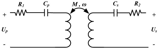
Figure 1.
S-S topology structure.
Neglecting the internal resistance of the primary and secondary sides, the current expression of the primary and secondary resonant loops can be obtained as follows:
Therefore, the output current of the S-S type compensation circuit is not affected by the load RL and the output of the system can be regarded as a constant current source. The resulting expression for the transmitted maximum power of the S-S resonant structure is given by the following:
From (2), the maximum transmitted power of the S-S resonant topology is jointly determined by the primary input voltage, the secondary output voltage, the system resonant frequency and the primary and secondary mutual inductance.
Considering the internal resistance of the primary and secondary side coils yields the overall input and output efficiencies of the system as follows:
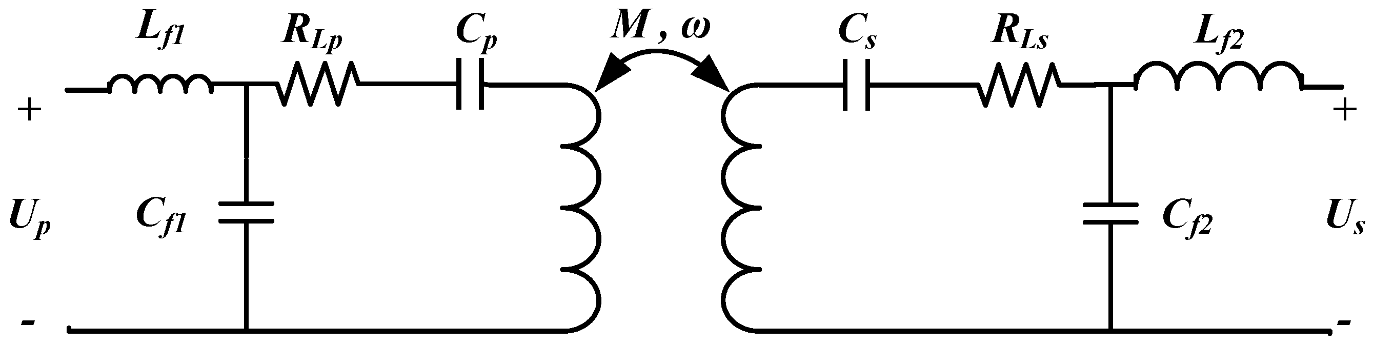
The structure of the bilateral LCC topology is shown in Figure 2.
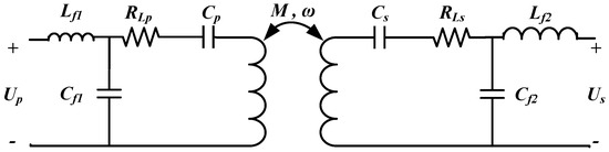
Figure 2.
LCC-LCC topology structure.
Neglecting the internal resistance of the primary and secondary coils, write the KVL equations for each circuit separately:
The expression for each loop current is obtained as follows:
In the context of the bilateral LCC resonant topology, the maximum transmitted power is defined by the following Equation (6):
When considering the internal resistance of the primary and secondary side coils, the system transmission efficiency is given as follows:
From (7), it can be seen that for the system where the input voltage, output voltage, resonant angular frequency and coupling mechanism are determined, the maximum transmitted power can be adjusted by adjusting the self-inductance value of the resonant inductor.
2.2. Comparative Topological Analysis
Typically, the S-S topology and LCC-LCC topology have better efficiency and transmission power. Furthermore, the system requires rotation, during which aligning the coil offset is not feasible. Therefore, the next step is to compare the transmission power, transmission efficiency and capacitive voltage stress of S-S topology and bilateral LCC topology at different offset angles.
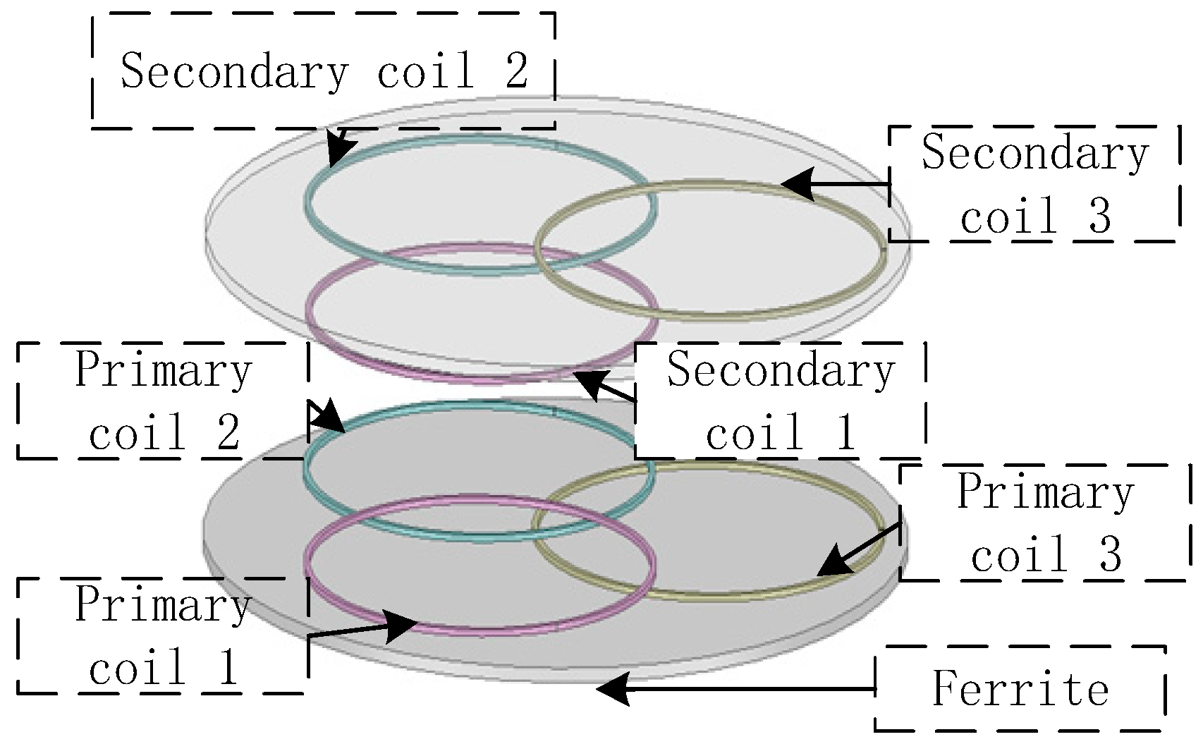
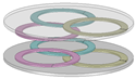
We will demonstrate this situation by means of the schematic diagram of the coupling mechanism part of the system shown in Figure 3. During the rotation of the receiver end, the system needs to adapt to a certain range of offset angles due to the existence of misalignment between the coils. In order to better assess the performance difference between the different structures, we used simulation verification to assess the performance difference between the two structures. The results are shown in Figure 4, in the coupling mechanism part of the simulation, we found that when there are mutual inductance fluctuations between one receiving end coil and three transmitting end coils, the maximum offset is about 7%. The total offset of the mutual inductance synthesis values of the three modules also reaches about 21% when repeated every 60°.
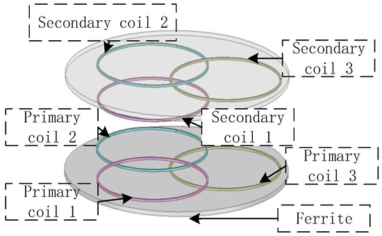
Figure 3.
Simulation model of a multi-coil coupling mechanism.
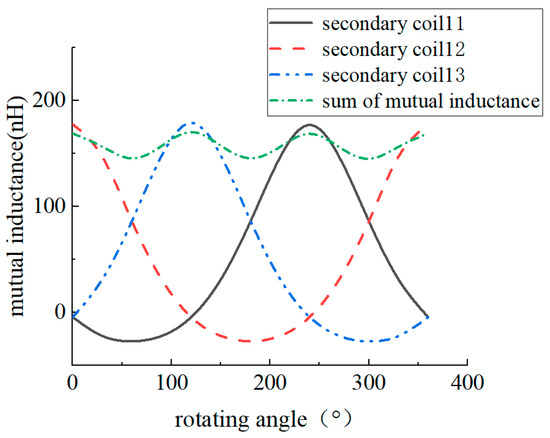
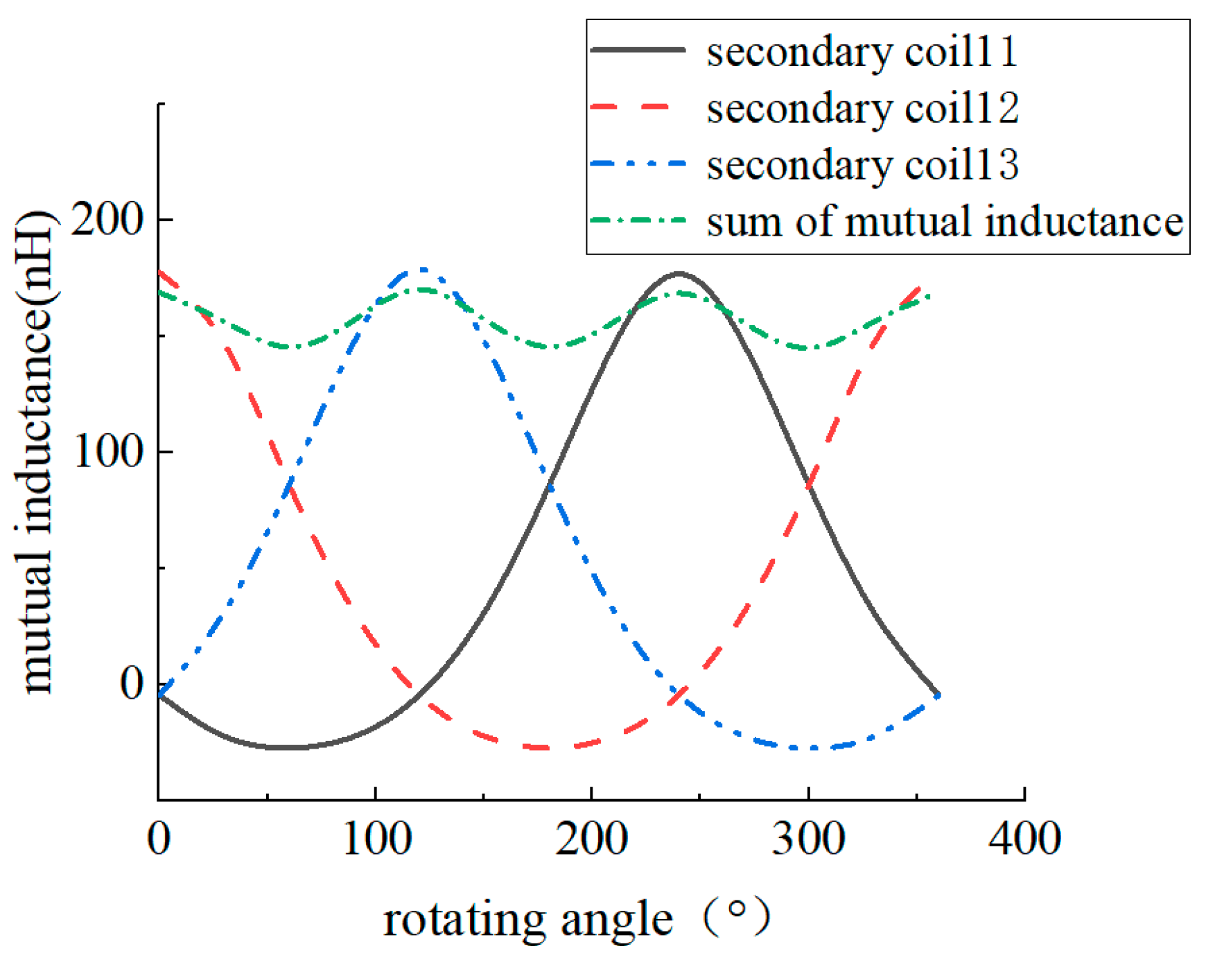
Figure 4.
Schematic diagram of single-turn mutual inductance wave synthesis.
According to the design of the coupling mechanism in the next section, it can be observed that the average value of mutual inductance is 5.95 μH, so the mutual inductance offset fluctuates between 4.76 μH and 7.2 μH. The transmitted power and efficiency of the resonant topology are analysed below with the fluctuation of mutual inductance offset range.
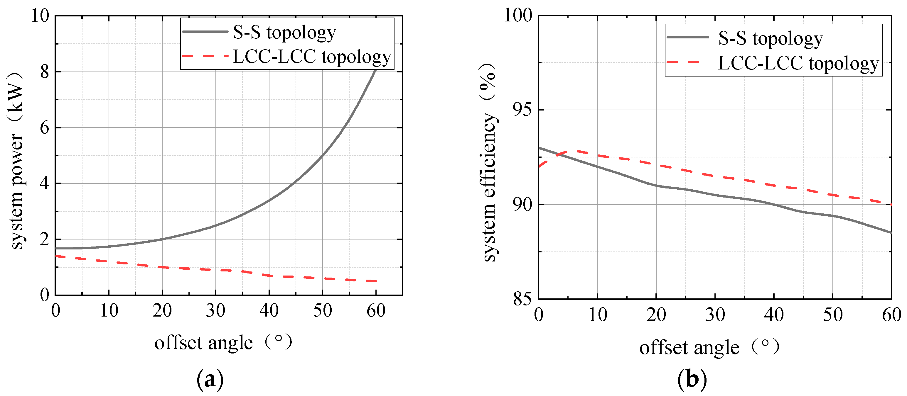
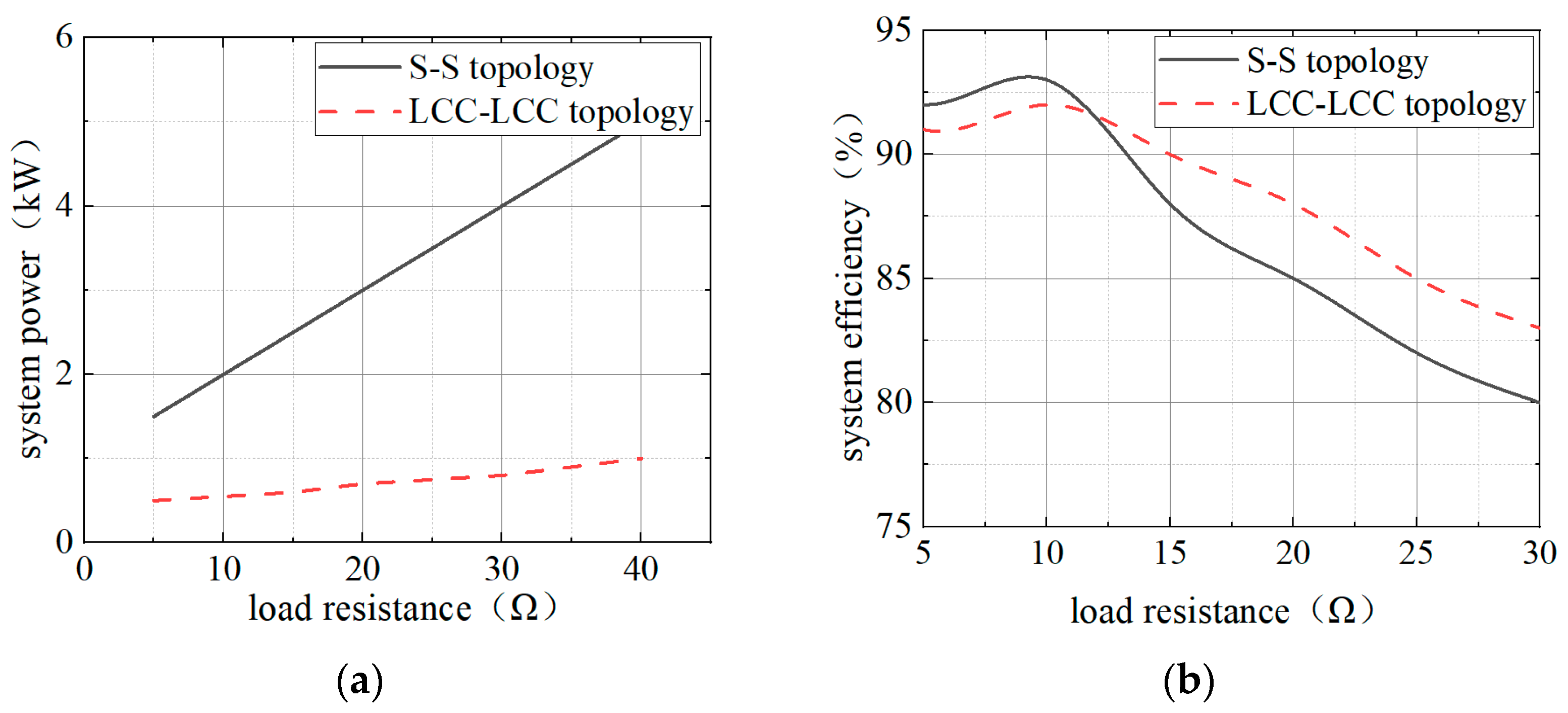
According to the above derivation, the mutual inductance values obtained from simulation at different offset angles are brought into the transmission power and efficiency equations, and the results shown in Figure 5a below are obtained, and it can be seen that the mutual inductance of the bilateral LCC topology is directly proportional to the transmission power and transmission efficiency, while that of the SS topology is inversely proportional to the mutual inductance, and the transmission efficiency is directly proportional to the mutual inductance. As the offset angle is varied, it can be seen that the magnitude of variation of the bilateral LCC topology is significantly smaller than that of the SS topology. In addition, the transmission power and transmission efficiency of the two topologies under varying loads are investigated, as shown in Figure 5b. Based on the above analyses, the bilateral LCC topology can provide more stable output under mutual inductance fluctuation and is more suitable for this system.
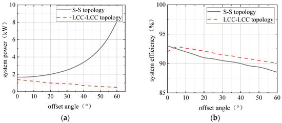
Figure 5.
System output characteristics vs. mutual inductance for different topologies. (a) System output power; (b) system output efficiency.
Through simulation, the relationship between each branch current and load resistance under different compensation topologies is investigated. From the simulation results in Figure 6, it can be seen that when the load resistance increases, the transmitted power of the SS compensation topology rises substantially, and the primary-side current rises significantly and is prone to overcurrent, while the efficiency decreases rapidly with the increase of the load; the power of the LCC-type compensation topology is more stable, and the transmission efficiency is also more stable than the SS topology.
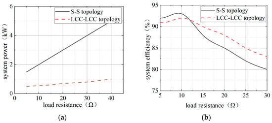
Figure 6.
System output characteristics vs. load variation for different topologies. (a) System output power; (b) system output efficiency.
The above simulation results show that, in the resonant state, the primary-side current Ip of the bilateral LCC circuit depends only on the input voltage, the resonant frequency, and the value of the compensating inductance, and does not depend on the load on the secondary-side rectifier bridge, or the coupling between the energy-transfer windings, which results in better self-adaptation.
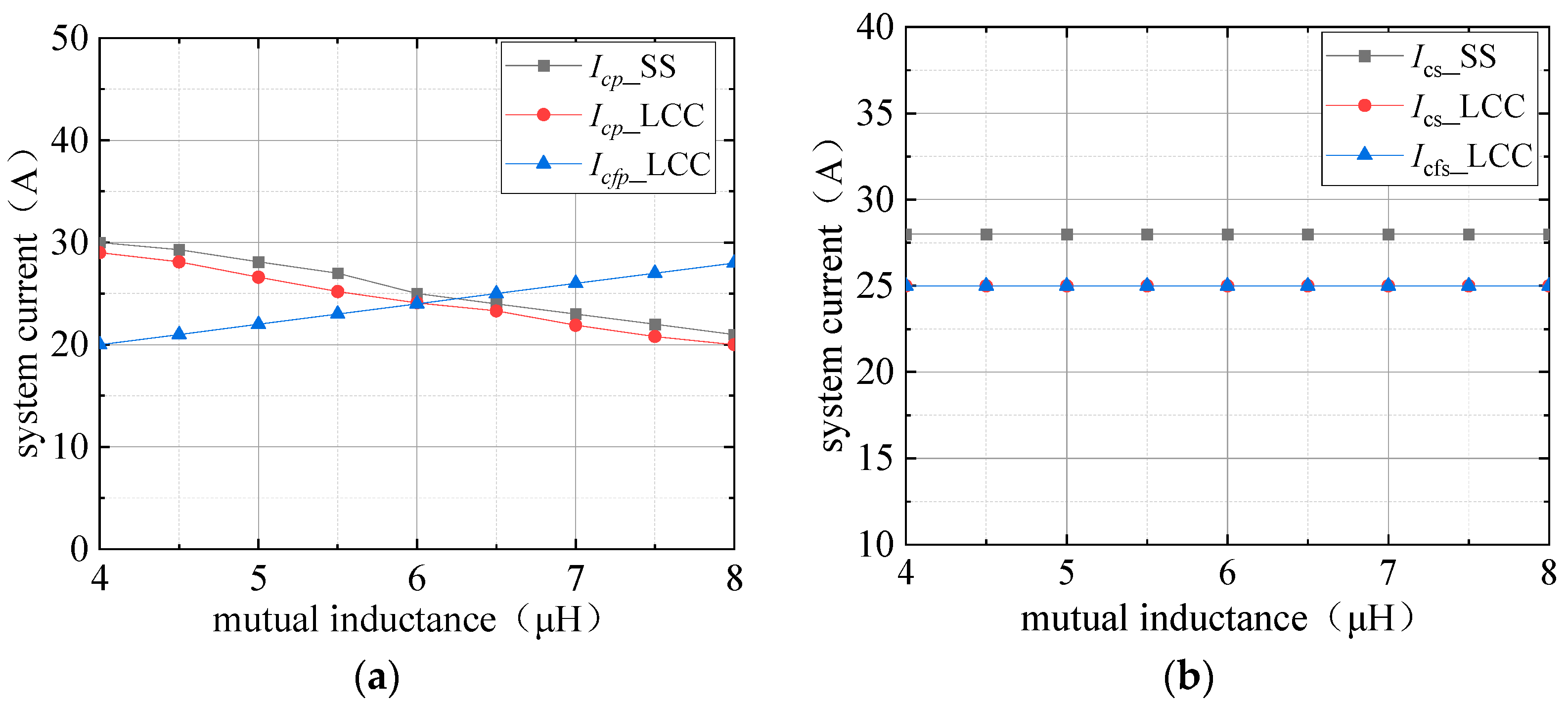
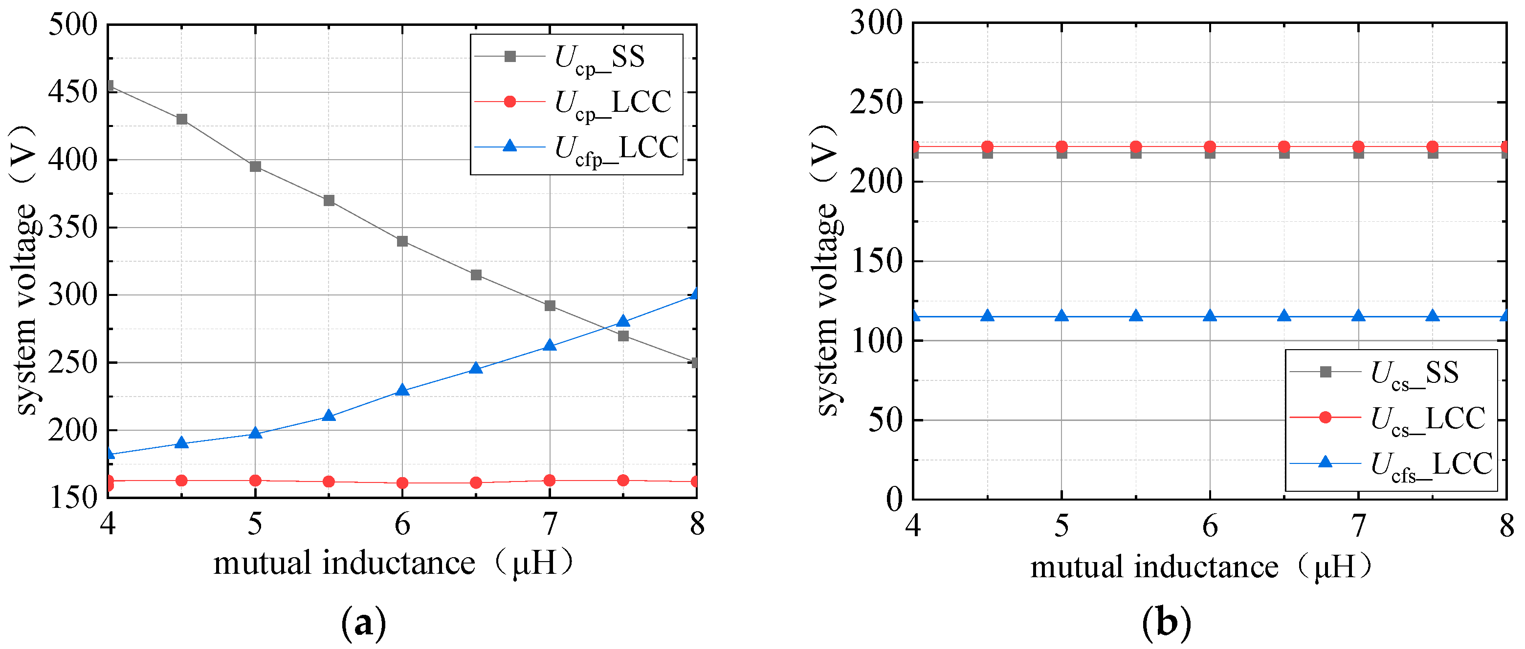
According to Figure 7 and Figure 8, the variations of the current stress and capacitive voltage stress of the two topologies can be clearly seen. From Figure 7a, it can be seen that the SS topology primary-side capacitive current is inversely proportional to the mutual inductance, and the LCC-LCC topology is proportional to the mutual inductance, but the overall transformation range is not large, and from Figure 7b, it can be seen that the values of the loop currents of SS topology and LCC topology do not differ much, and the sensitivity to mutual inductance is close to the same level. From Figure 8a, it can be seen that the variation of capacitive voltage stresses of the SS topology is larger; from Figure 8b, it can be seen that the voltage stress of a single capacitor of the SS topology is slightly larger than that of a single capacitor of the bilateral LCC topology throughout the mutual inductance fluctuation range. Therefore, the LCC-LCC topology is finally selected as the resonance compensation.
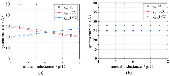
Figure 7.
Current RMS values with different mutual inductance. (a) The primary side; (b) the secondary side.
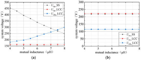
Figure 8.
Capacitive voltage stresses with different mutual inductances. (a) The primary side; (b) the secondary side.
Based on the derivation of the above equations, the parameters of the resonant topology are analysed theoretically. When the bilateral LCC output is a constant current source, the following equation must be satisfied:
In the compensation structure of bilateral LCC, the secondary side impedance is as in Equation (9):
Then, the reflected impedance of the secondary to the primary can be expressed as follows:
The input impedance of the bilateral LCC compensation network can be obtained as follows:
Included among (11), , from Equation (8), the first term of Equation (11) is zero.
According to Equation (12), the minimum reactive power loss can be achieved when ZN is zero, viz:
At this time, the system operates in a resonant state, and the input impedance the Zin of the bilateral LCC presents a purely resistive nature, i.e., the following:
According to the above equation, the resonance condition can be organised as follows:
In wireless transmission systems, the resonant frequency is usually set to 85 kHz. The primary and secondary edges are of symmetric design, i.e., the primary and secondary edges have the same parameters. According to Equation (9) and the ZPA condition, the parameters can be derived as in Table 1.

Table 1.
Specific parameters of bilateral LCC topology.
The system is powered by the solar wing, and the typical power supply range is 80~120 V. Therefore, the input voltage of the system is set to 100 V. According to the design of the coil of the coupling mechanism in Section 3, the coils between the transmitter ends are decoupled, i.e., the mutual inductance of the coil of the transmitter end is 0, and the self-inductance is designed to be 22.3 μH and the mutual inductance is designed to be 5.95 μH. Based on the 5 kW transmission power requirement, as outlined in Section 3, the output current is set at 25 A, resulting in a lithium battery’s equivalent resistive load of 8 Ω. According to the transmission power requirement of 5 kW, the output current is set to 25 A according to the design in Section 3, so the equivalent resistive load of the Li-ion battery is set to 8 Ω. The simulation schematic is shown in Figure 9, considering that the whole topology is in the process of dynamic rotation, but due to the small fluctuation of the mutual inductance, the simulation is taken as the initial stationary state. Since decoupling is achieved between the coils, the whole simulation is set in the form of three independent modules connected in parallel.
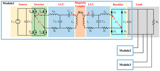
Figure 9.
System simulation topology schematic.
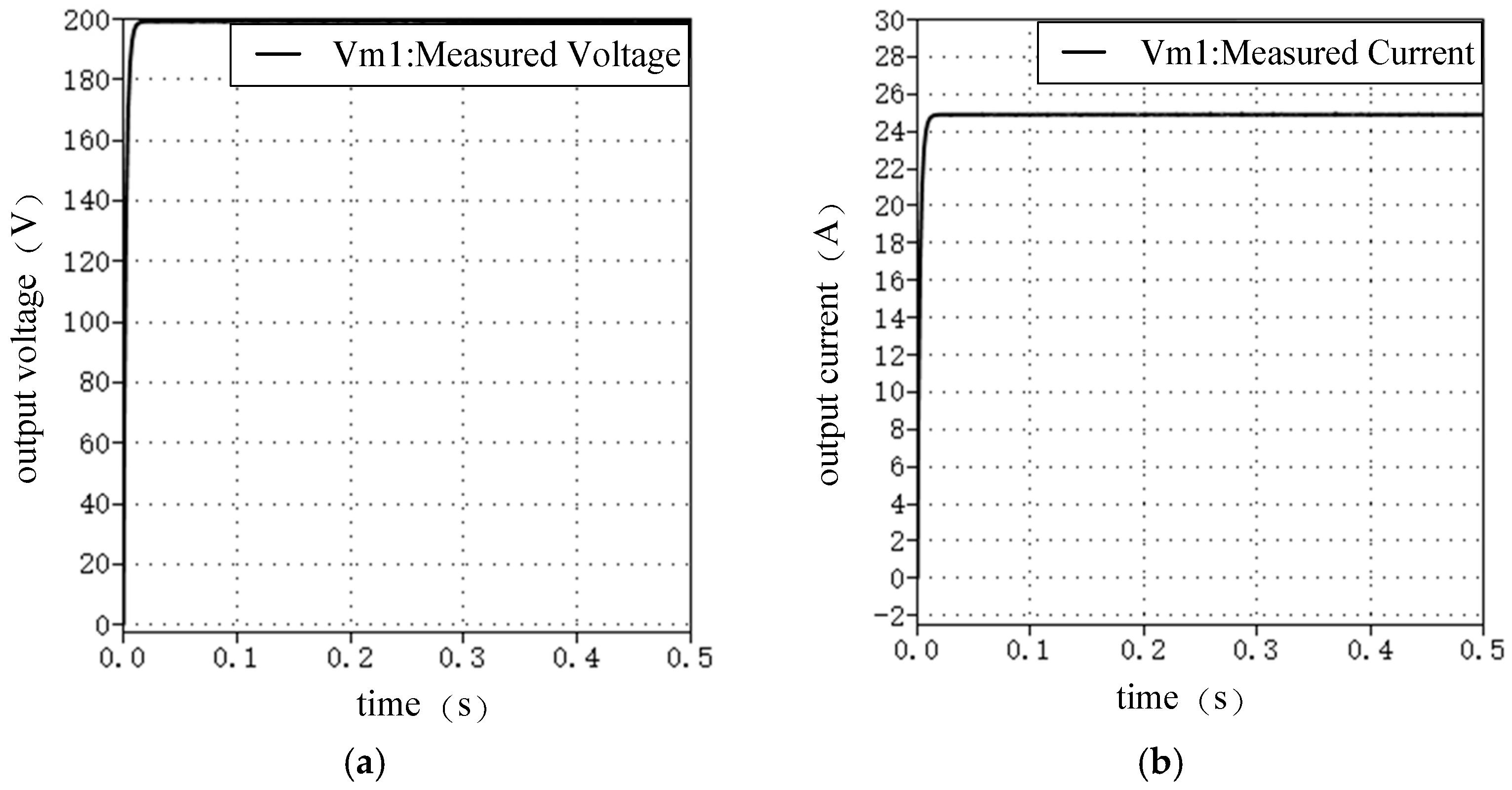
The simulation results are shown in Figure 10, which shows that the system output current reaches 25 A, and the bilateral LCC topology input and output load matching can achieve a constant-current output.
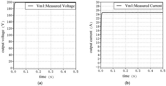
Figure 10.
System load output results. (a) Output voltage; (b) output current.
3. Magnetic Coupling Mechanism Design
3.1. Decoupling Analysis
Generally speaking, many-to-many coils exist with transmitter/receiver mutual coupling, resulting in reduced efficiency; the complete decoupling of the coils can be achieved by changing the multi-coil spacing. The coupled coil model is shown in Figure 11. Ideally, complete decoupling can be achieved by adjusting the mutual position of the coils at this point, i.e., M12 = M23 = M13 = 0. However, the simulated losses in this coupled form have low utilisation of ferrite and high iron losses, so a pizza structure is proposed. The structure when applied to a three-phase power supply has many benefits in terms of increasing the volumetric power density, reducing the magnetic stray field, and reducing the necessity of filtering compared to a single-phase one. Future work will conduct more detailed analyses, particularly focusing on weight and loss considerations. The author applied the structure to a redundant structure in the form of many-to-many single-phase inputs with a view to improve the mutual inductance fluctuations and reduce the core losses of the coils during rotation.
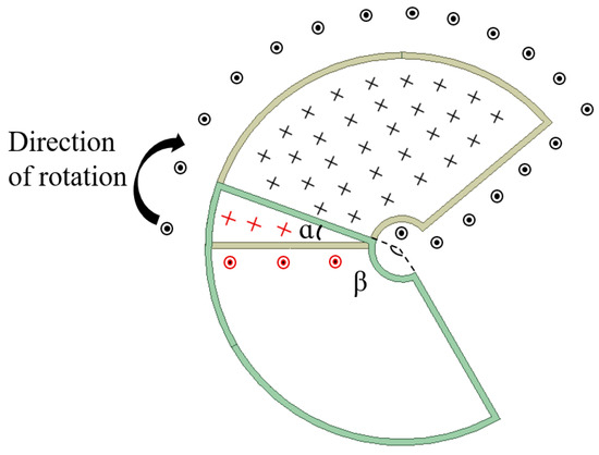
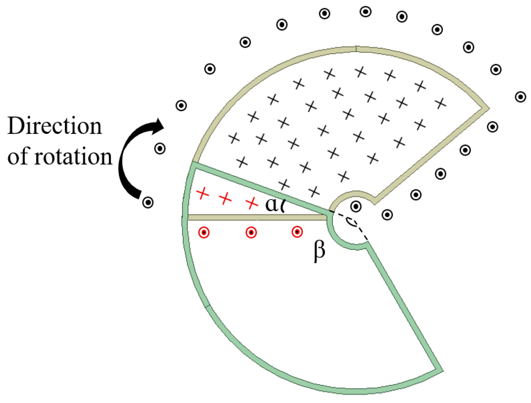
Figure 11.
The decoupling of magnetic lines of force and the position of two neighbouring coils.
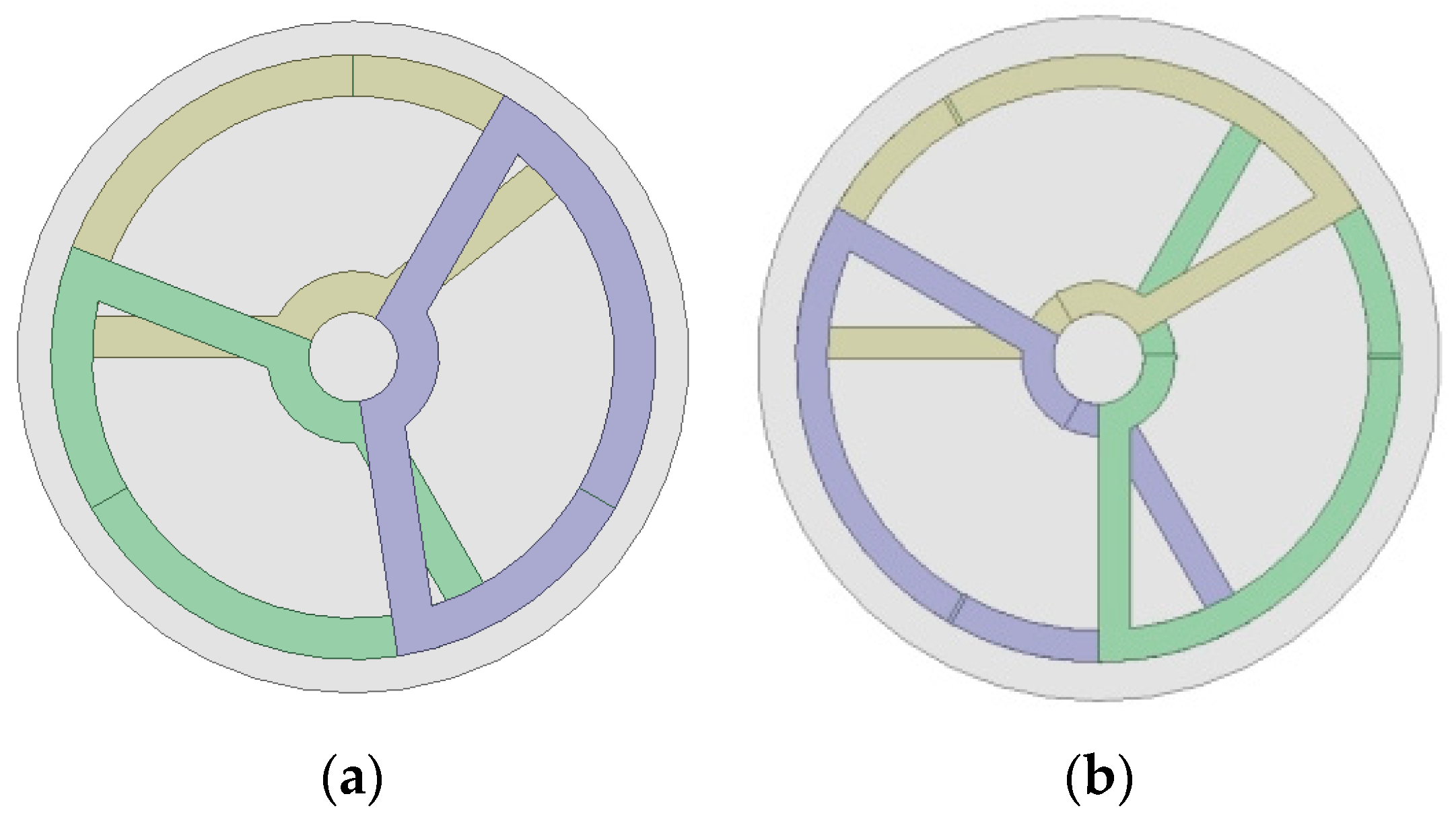
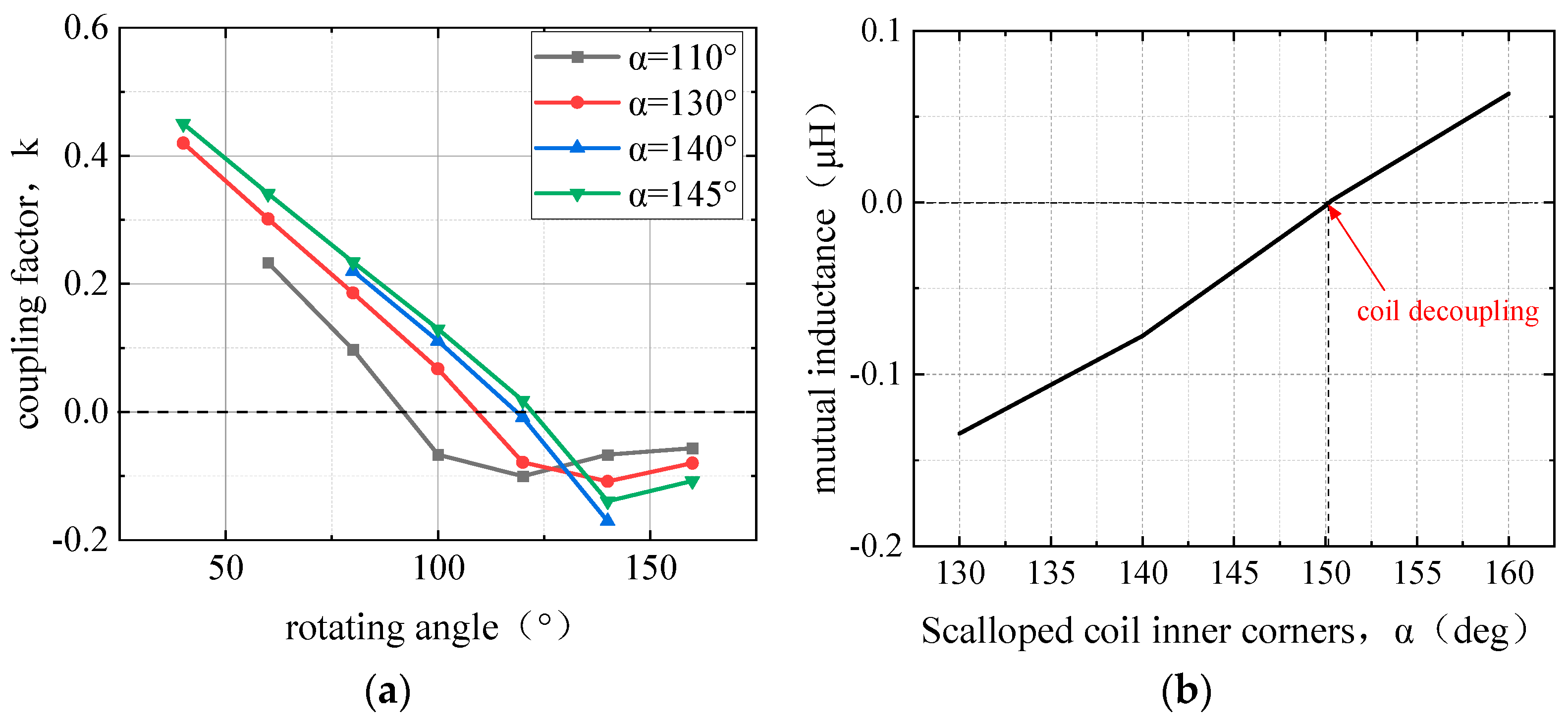
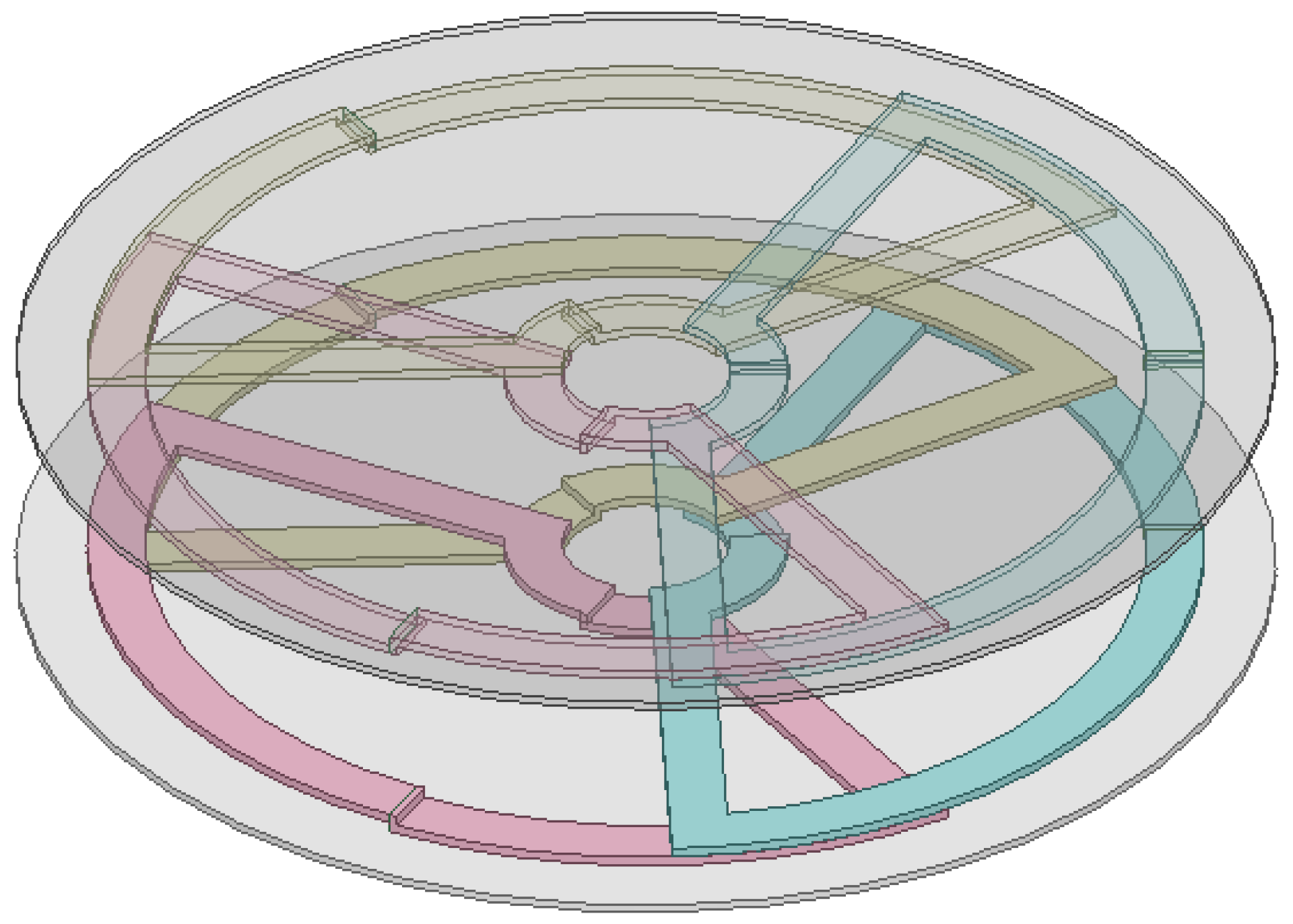
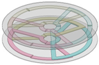
In order to ensure that the three coils are uniformly arranged, the rotational angle (β-α) is set to 120°, at which time the coupling coefficient between the coils is exactly zero when the inner angle of the sector β is 140°, i.e., complete decoupling is achieved. Considering the actual arrangement of the coils, further optimisation is carried out by changing the simulation model from one in which the coils are stacked high in sequence to one in which the coils are placed on top of each other, as shown in Figure 12. In the former case, due to the fact that the highest coil is farther away from the ferrite, decoupling cannot be achieved if the three coils have the same shape, and at the same time, it occupies the height of the three layers of coils. In contrast, the stacked arrangement of the three coils can be closer to the ferrite to increase the self-inductance and reduce the height of the space occupied by the coils, which improves the symmetry between the coils well compared to the sequential stacking of the coils in the high-stacking model. Therefore, considering the decoupling situation when the coils are overlapped and arranged, the simulation results are shown in Figure 13, which shows that decoupling can be approximated when the coil angle is 150.2°.
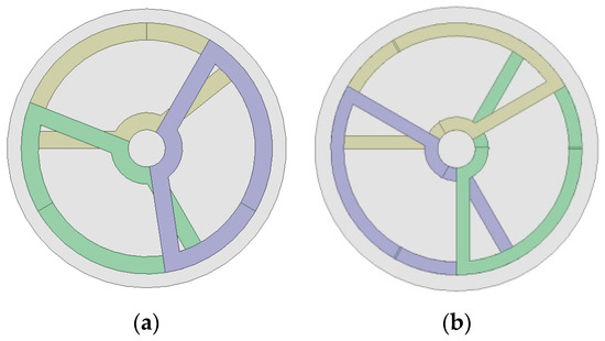
Figure 12.
Sector simulation mode. (a) Coils stacked high in sequence; (b) coils overlapping each other.
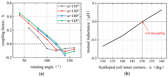
Figure 13.
Variation of sector internal angle and coupling coefficient under different models. (a) coils stacked high in sequence; (b) coils overlapping each other.
3.2. Parameter Design and Performance Comparison
Under the condition of the same transmission capacity, or the condition of the same mutual inductance of the magnetic coupling mechanism, the symmetric magnetic coupling mechanism has the highest efficiency, so the primary and secondary edges of the magnetic coupling mechanism in this design adopt the symmetric design, and the transmission power expression is as follows:
where US and IS are the induced voltage and coil current at the receiving end, ω is the alternating current angular frequency, and M is the mutual inductance of the magnetic coupling mechanism, which is equivalent to the power input voltage and current at the receiving end.
When the output power is certain, Ip/Is there is an inverse relationship, the conduction loss is the smallest, IP = IS = I, that is, the original vice-side current is the same. According to f = 85 kHz (adjustable), 5 kW transmission power, there are
Substituting the values of f and Po yields: . In the case of transmission distance of 50 mm, the specific design process of the turns of the coupling mechanism is as follows. First of all, take the total current as 25 A; at this point, the mutual inductance is calculated to be 15 μH, so the single transmitting coil should be designed to be greater than 5 μH. We can use the finite element simulation to get the relationship between the number of coil turns and mutual inductance. When the number of coil turns is greater than or equal to 6, the mutual inductance is greater than 5 μH, and the equivalent mutual inductance is 5.95 μH, which meets the design requirements. It can be seen that the new simulation model is reduced compared with the original simulation model, as shown in Table 2. The equivalent mutual inductance is 5.95 μH, which meets the design requirements, and the comparison of the parameters of the two coupling mechanism simulation models is shown in Table 2, which shows that the new simulation model reduces the number of turns of the coil compared with the original simulation model, and still provides the mutual inductance value required for the normal operation under the case of radius reduction, which reduces the weight and size of the coupling mechanism to a certain extent.
Table 2.
Comparison of coil parameters of two models.
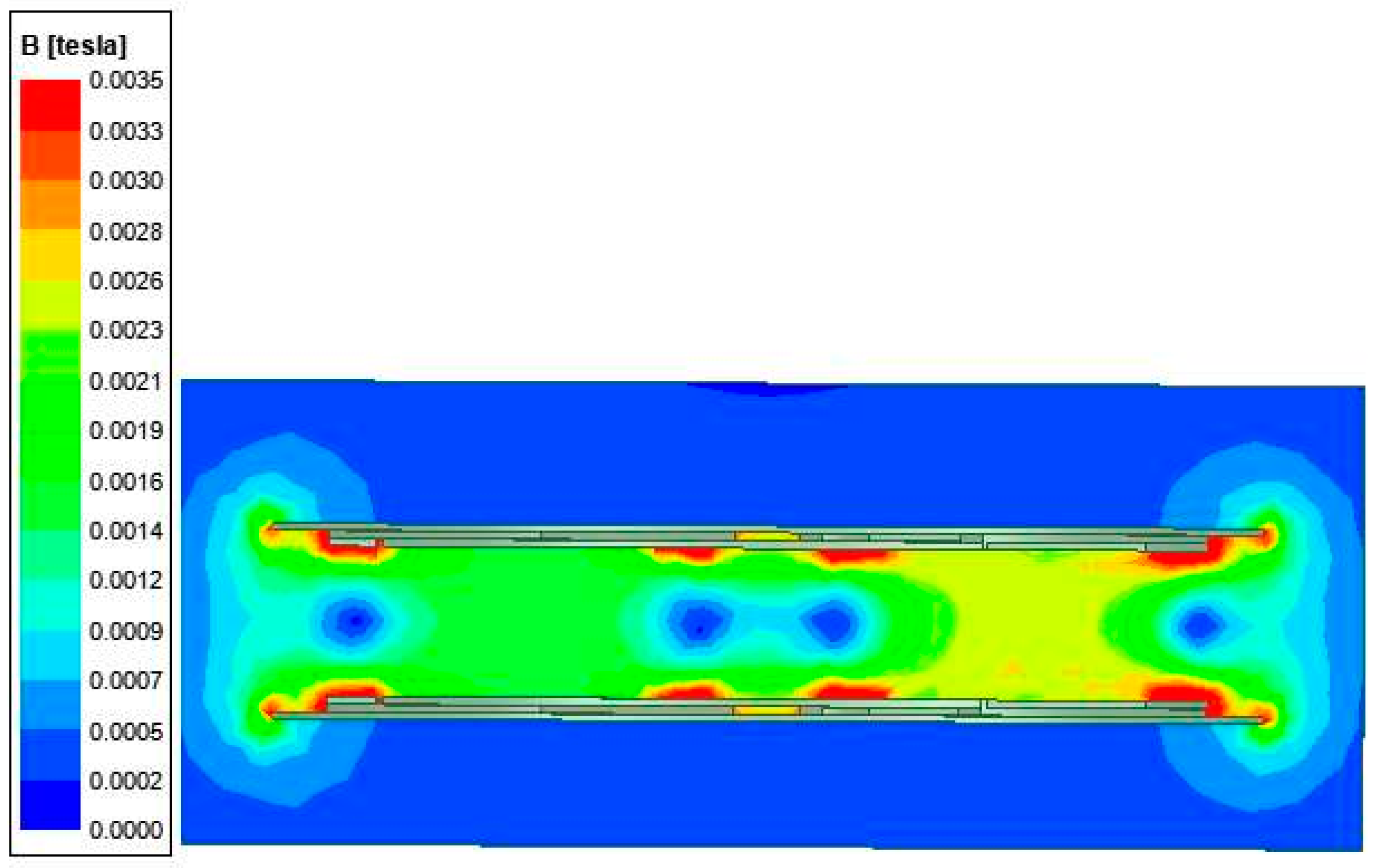
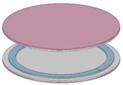
The final model of the coupling mechanism is obtained as shown in Figure 14. The magnetic density diagram of the coupling mechanism is shown in Figure 15, and it can be seen that the distribution of the magnetic field at this time is more reasonable, and the maximum value of the magnetic density is 65.1 mT, which has not reached the saturation state of the ferrite 500 mT, and the system is reasonably designed.
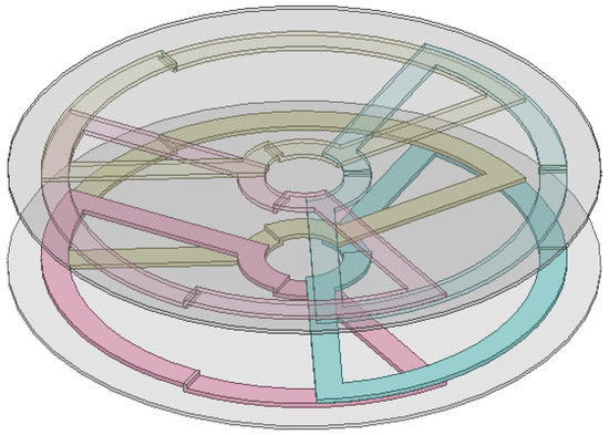
Figure 14.
Optimized magnetic coupling mechanism form.

Figure 15.
Multi-coil magnetic density diagram.
3.3. Comparison of the Advantages and Disadvantages of the Coupling Mechanism
In order to make a better comparison, the single-coil parameters should be as consistent as possible with the multi-coil parameters, so the circular radius is set to 135 mm and the number of turns is 7, when the mutual inductance value of the coil is greater than 15 μH, which meets the requirements. Loss analysis yielded parameters listed in Table 3 and Table 4; specifically, the single-coil model exhibited an iron loss of 11.4 W, a copper loss of 138 W, and an aluminium plate loss of 67.8 W. Similarly, the power loss analysis is carried out for the circular triple-coil and the sector triple-coil, and the parameters are shown in Table 3 below, and the loss parameters obtained by establishing the corresponding simulation model are as follows, and the loss of the optimized model is reduced by 16.4% compared with that of the pre-optimization loss.
Table 3.
Comparison of the power consumption of single coil and multi-coil models.
Table 4.
Experimental values of coil self-inductance and internal resistance.
Through the analysis and comparison, it can be found that the power density of the single coil is 742.5 W/kg, which is higher than the two multi-coil power densities, and the multi-coil power density decreases by about 3%, and the optimised power density also decreases compared with the previous one, but it is within the acceptable range. The multi-coil form can improve the fault tolerance of the system, and the current flowing through each coil is 1/3 of the current flowing through a single coil, which greatly reduces the specification requirements for the coil Leeds wire, and the current is reduced, and the aluminium plate loss and iron loss are also reduced; at the same time, the optimized multi-coil makes full use of the ferrite space, which makes the ferrite loss much lower than that in the pre-optimized coil form.
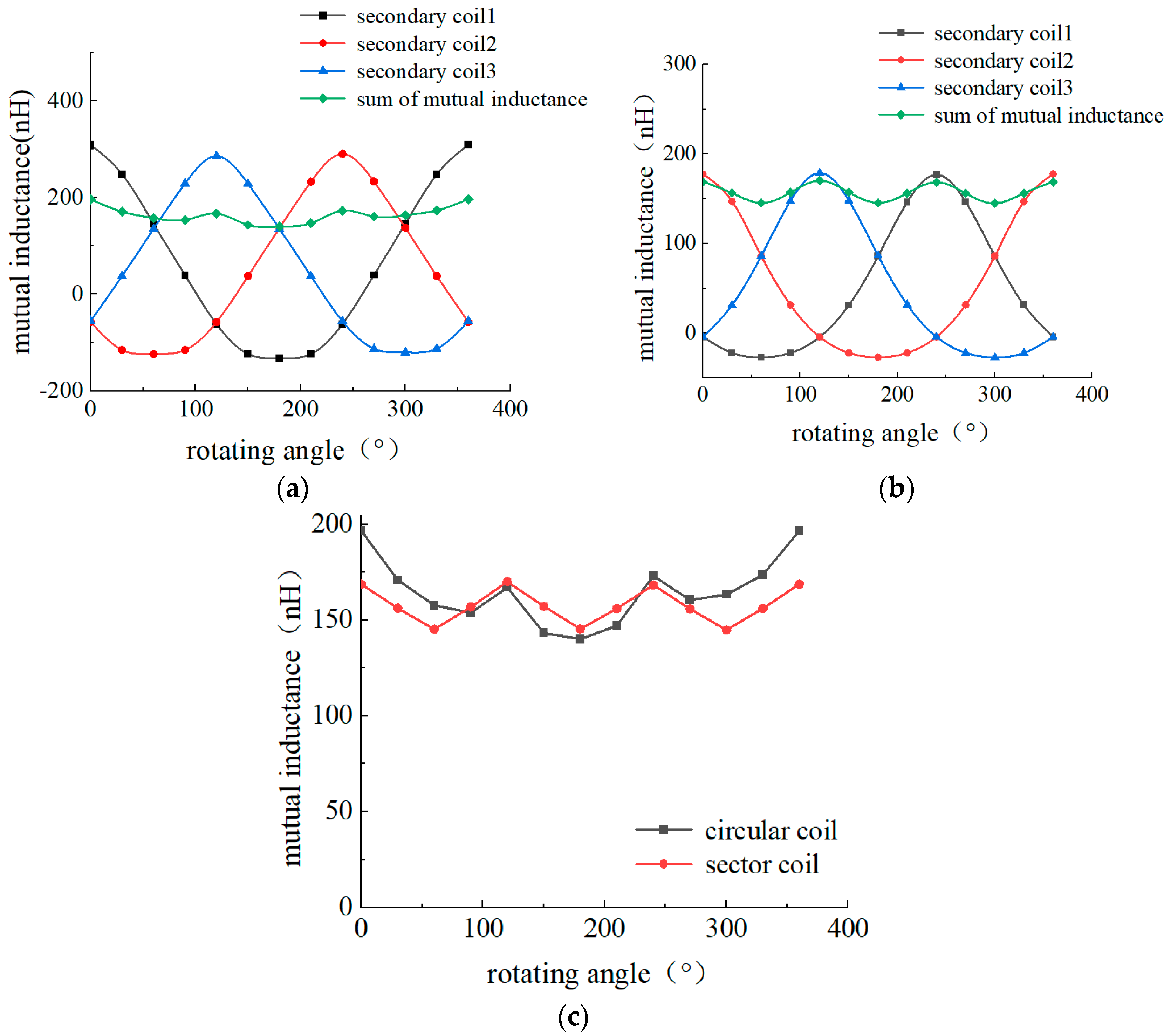
Due to the rotational symmetry of the designed magnetic coupling mechanism and the special design of position decoupling, it can be seen that the synthetic mutual inductance is almost stable in a straight line (green in the figure), i.e., the total output power with the positional influence of the slip ring rotating with a certain degree of change, the mutual inductance and the output power is more stable, mutual inductance fluctuations of less than 7%, the receiving coil single-turn mutual inductance of about 5.95 μH at this time, the system total single-turn mutual inductance amount of 18.6 μH. The total single-turn mutual inductance of the system is 18.6 μH, which meets the minimum mutual inductance requirement of the system to output 5 kW of power in the forward direction, and the system completes the decoupling and works stably at full power.
Comparing the mutual inductance fluctuation of the new three-sector coil as shown in Figure 16c, it can be seen that the mutual inductance fluctuation is improved compared with the circular three-coil; the mutual inductance fluctuation is about 6%, but there is still a large mutual inductance generation.
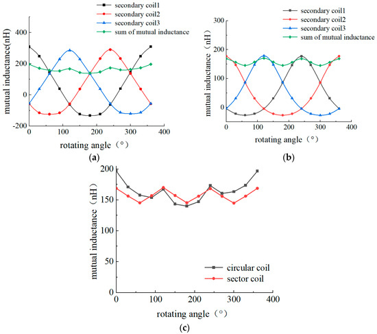
Figure 16.
Mutual inductance fluctuation during coil rotation. (a) Circular triple coil form; (b) sector triple coil form; (c) comparison of two forms of mutual sensory fluctuations.
According to the above comparative analysis, it can be found that the optimised coil model greatly reduces the overall system loss, especially the core loss, compared with the traditional three-circular multi-coil form, and improves the system transmission efficiency; at the same time, the mutual inductance fluctuation is somewhat reduced compared with the traditional three-circular form, which improves the stability of the system, but the mutual inductance fluctuation is still large, which is not conducive to the system stable transmission.
3.4. Experimental Verification
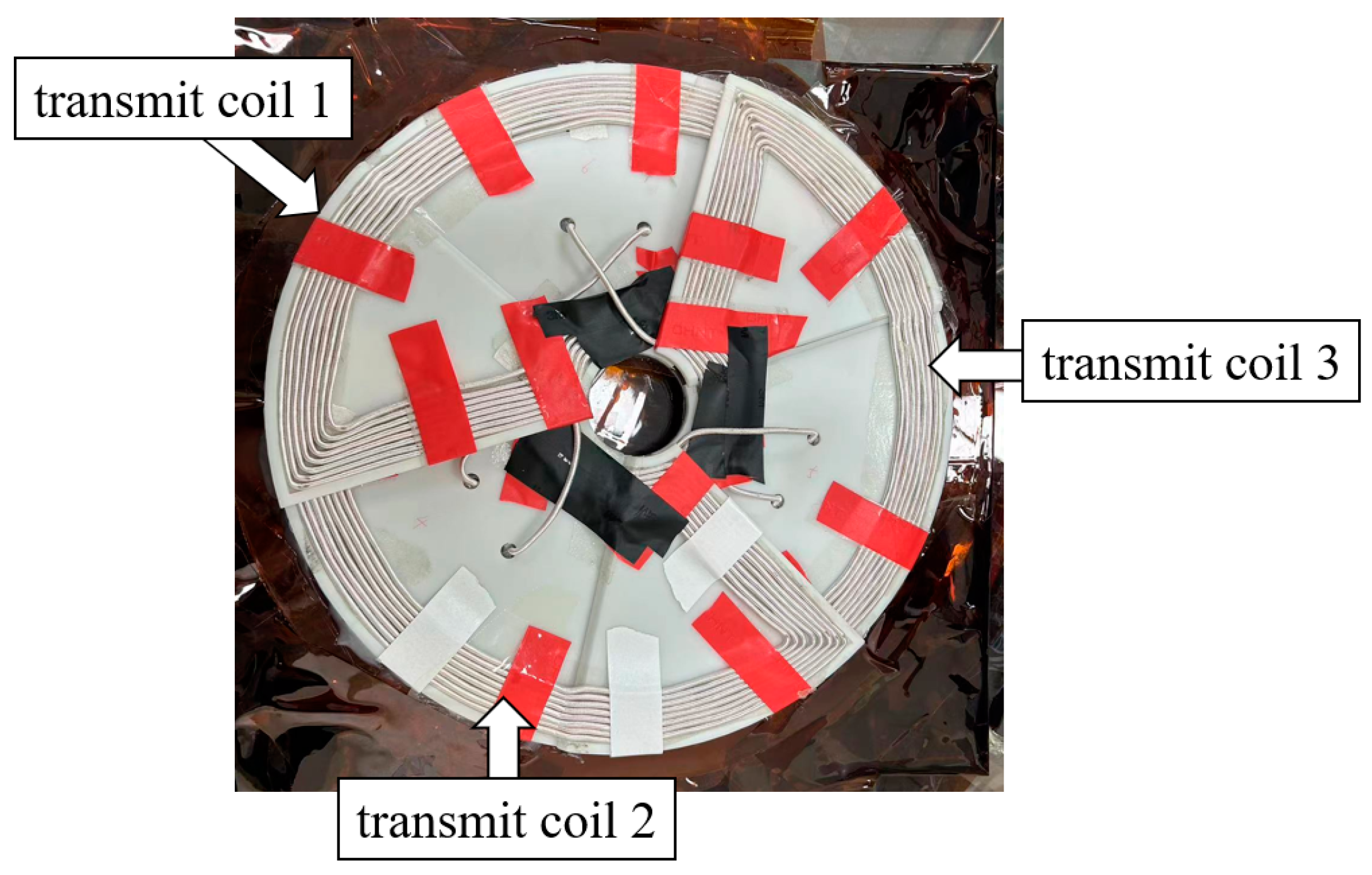
According to the above parameter design of the resonant network and the coupling mechanism, the devices of the wireless power supply system are selected and the platform is built. The coupling mechanism coil is shown in Figure 17.
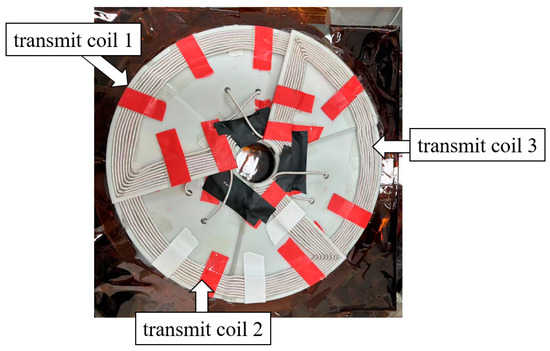
Figure 17.
Coupling mechanism coil.
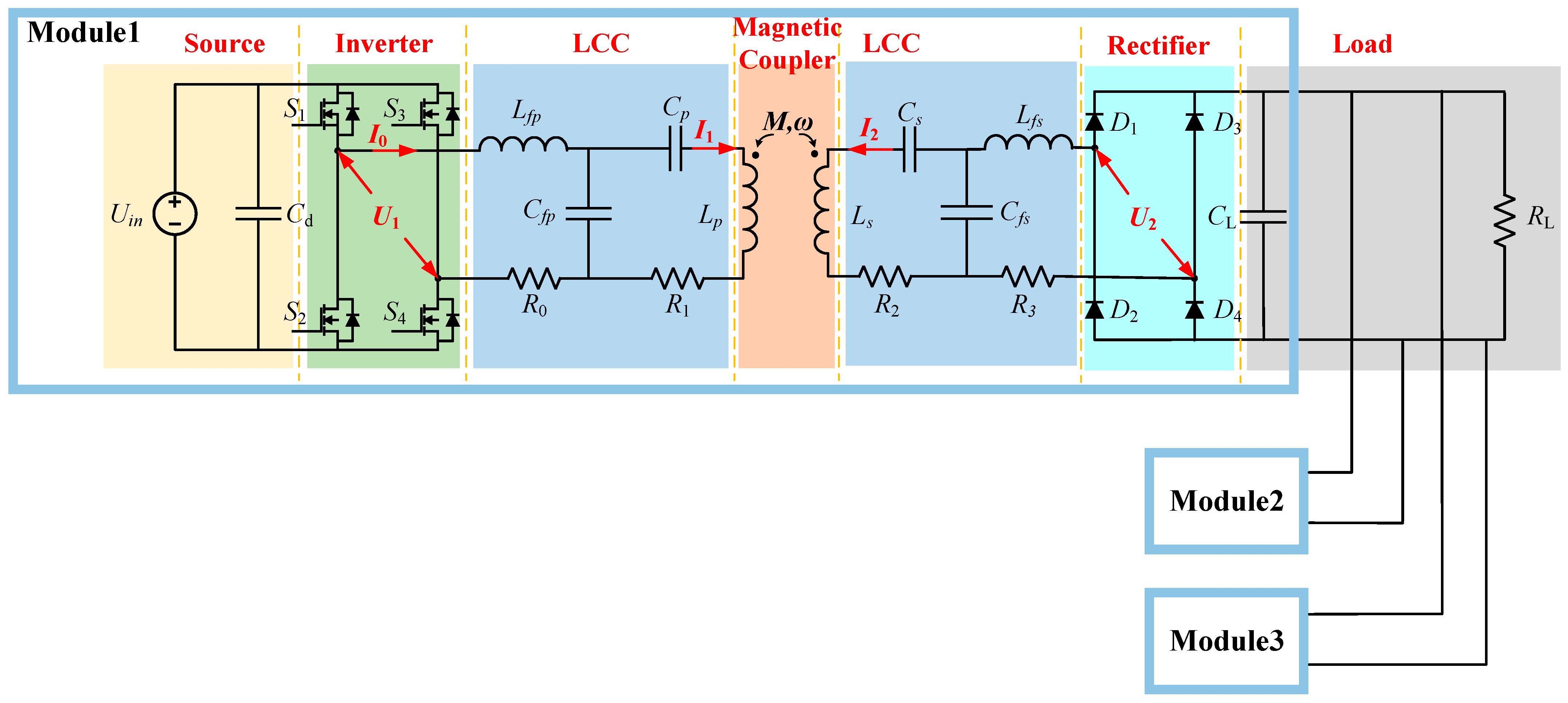
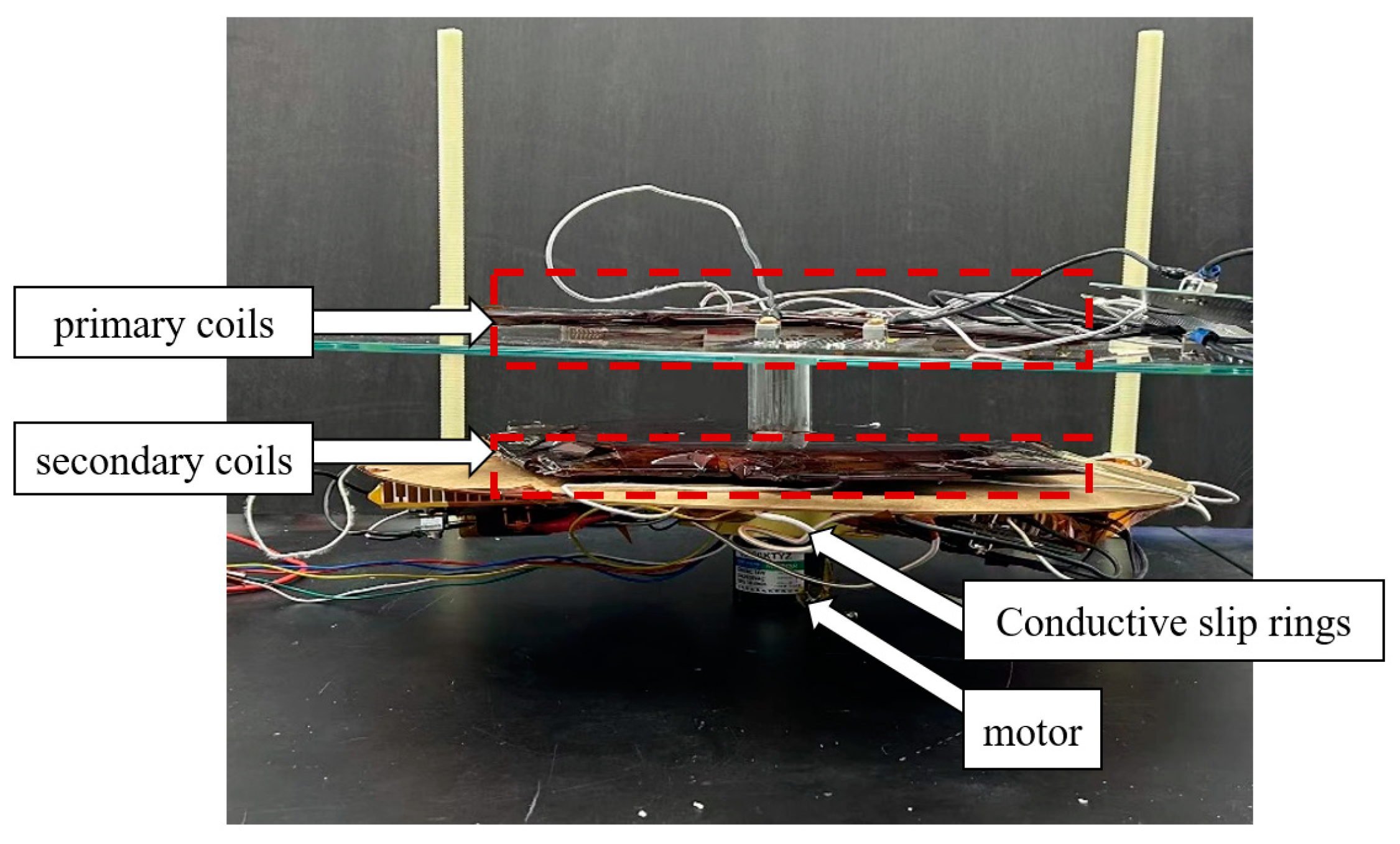
As shown in Figure 18,The system includes a power supply, three groups of high-frequency inverter sources, an LCC-LCC resonance circuit, a coupling mechanism, a rectifier filter circuit and electronic load, etc., in which the coupling mechanism primary side structure is stable and connected to each group of pathways with the corresponding inverter sources, respectively, and the vice-side structure is fixedly connected to the motor; in order to avoid the problem of winding, the rectified output of the vice-side is connected to a conductive slip ring, and then connected to the electronic load through the slip ring, enabling 360° free rotation of the secondary side.
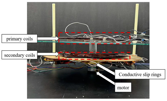
Figure 18.
System side view.
At the same time, in order to avoid winding during rotation, the LCC as well as the rectifier are fixed underneath the vice-side coupling mechanism, as shown in Figure 19, and the motor and the rotating shaft are connected together through the coupling to drive the whole vice-side to rotate.
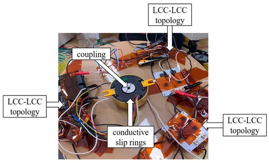
Figure 19.
Schematic diagram of the vice-side resonance circuit and rotor connection method.
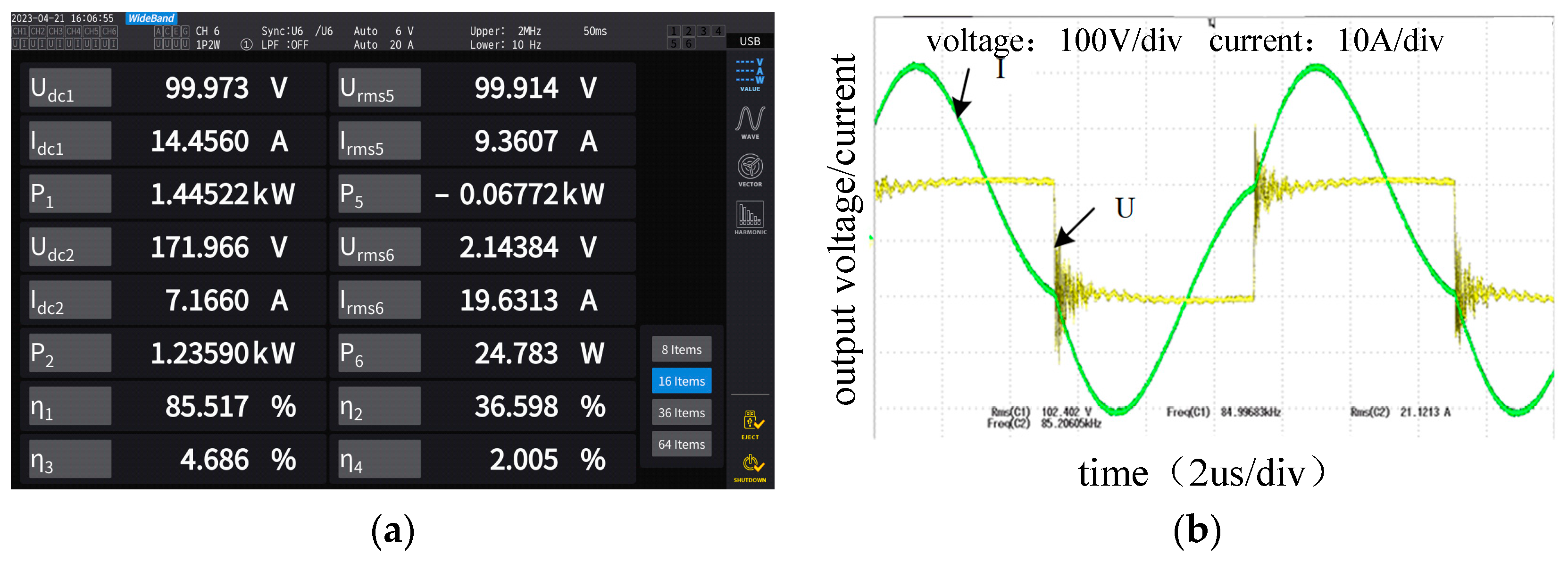
There are three modules in the system. In the stationary state, let one of them work. Set an input voltage of 100 V. The output power and efficiency, inverter output voltage and current waveforms obtained are shown in Figure 20. The duty cycle of the inverter is 48%, and the frequency output is 85 kHz. At this time, the input power of the single-module system is 1.45 kW, the output voltage is 172 V, and the output power is 1.23 kW. At this time, the efficiency of the system is 85%.
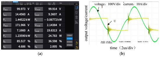
Figure 20.
Experimental results of single-module output characteristics. (a) Output power efficiency interface; (b) inverter output voltage and current waveforms.
Since the other two circuits are not energized under single-module operation, the coils are not fully decoupled at this time, and at this time, the working module will have an impact on the other two modules, resulting in the emergence of induced voltages, which affects the output power and efficiency of the system. Consequently, the inductive voltages of the other two coils were tested under both open-circuit and loaded conditions. When one of the transmitting ends does not work, the inductive voltage of the coil is tested; when the inactive coil is disconnected from the system load, at this time, the value of the inductive voltage of one of the coils is 6.89 V. When the inactive coil is connected to the load, the value of the inductive voltage of one of the coils at the end is 7.41 V; obviously, the emergence of the inductive voltage, to a certain degree, affects the output power and efficiency of the system for single-module operation.
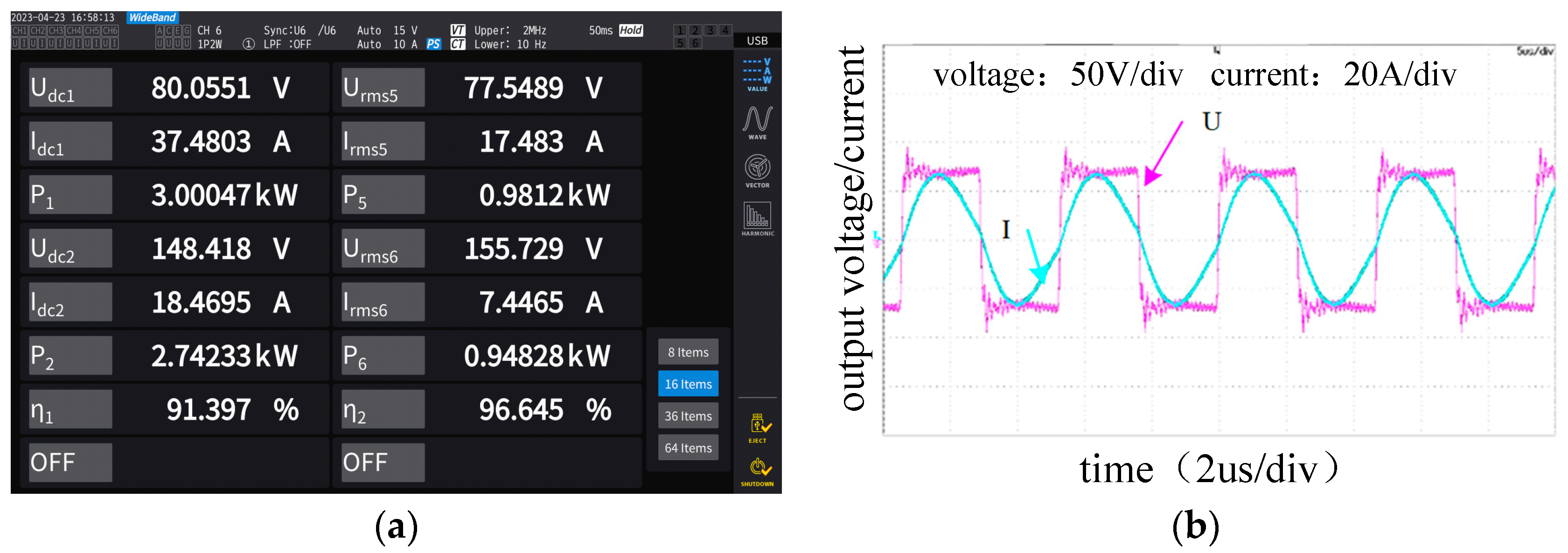
When operating in multi-module mode, the input voltage is set to 80 V. The outputs of the power analyser and the inverter waveform are presented in Figure 21. At this time, the output power of the system is 2.7 kW, the transfer efficiency of the coupling mechanism is 96%, and the system efficiency is 91%, and the efficiency of the system is improved compared with that under single-module operation, which further proves that there is a coupling problem in the system under single-module operation that affects the overall output efficiency of the system.
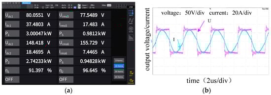
Figure 21.
Static output of multi-module system. (a) Output power efficiency interface; (b) inverter output voltage and current waveforms.
On this basis, the efficiency of the system is tested and analysed, and the coil loss, resonant capacitor loss, magnetic core loss, and rectifier bridge loss are compared and analysed to obtain the proportion of each loss, offering a foundation for optimizing the efficiency of the system. Under the condition of an 80 V input and 8 Ω constant load, the efficiency of the system from primary input to load, the efficiency of the system from primary input to secondary output, and the efficiency of the rectifier bridge are tested, respectively, so as to obtain the magnetic coupling resonance loss and the rectifier bridge loss of the system. The experimental results show that when the primary-side input power reaches 3 kW and the secondary-side output power reaches 2.74 kW, system efficiency reaches 91.4%, coupling mechanism transmission efficiency reaches 96.5%, and the rectifier bridge efficiency reaches 98.2%.
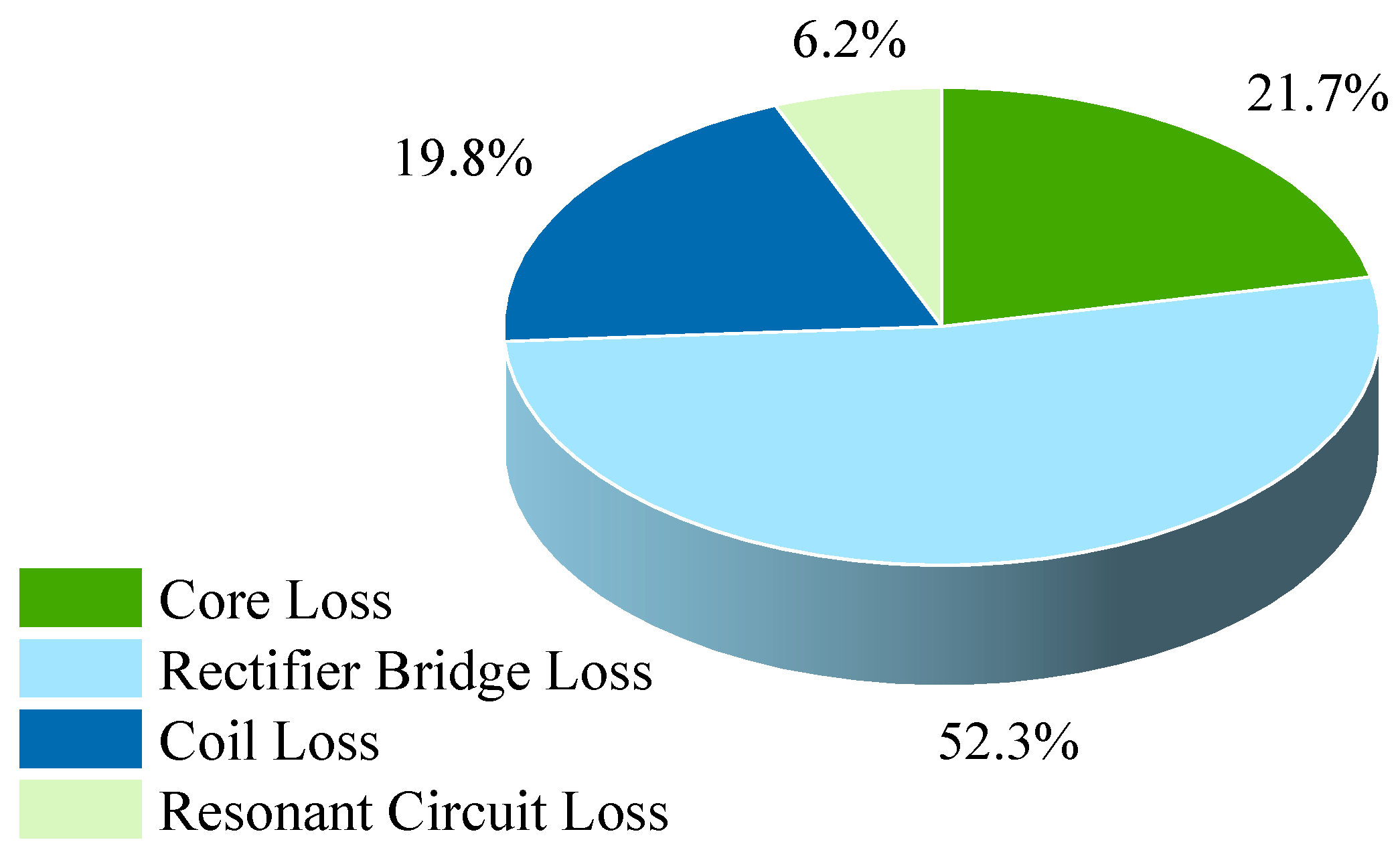
The experimental results indicate that the total losses of the magnetically coupled resonant section and rectifier bridge section of the system are 51.4 W and 136 W. Using the loss formula, we can calculate that the coil copper loss is 23.3 W, the resonant circuit loss is 16.1 W, and the magnetic core loss is about 56.4 W. In Figure 22, it can be seen that the rectifier bridge loss accounts for a large area, and since the rectifier bridge loss is as close as possible to that of the magnetic resonance element close, power electronic devices with high efficiency are used as much as possible as the front and rear electronic transformations of the system. In the coupling mechanism loss, copper loss accounts for the largest proportion, so, in the design of the coupling mechanism, should be as low as possible in the coil turns to achieve the system design requirements.

Figure 22.
System loss percentage.
4. Conclusions
This study explores a resonant topology optimized for a fault-tolerant rotating wireless energy transmission system, pivotal in aerospace power supply. It introduces a planar rotating multi-coil coupling mechanism ensuring consistent power and efficiency during rotation to significantly improve the system’s safety and longevity.
The key findings of this study include:
- (1)
- The circuit model of multi-coil parallel-connected wireless power transmission is established, the resonant topologies in the wireless power transmission system are analysed, and the transmission performance of SS topology and bilateral LCC topology is determined to meet the requirements according to the basic characteristics of each resonant topology and the requirements of the multi-coil parallel-connected wireless power transmission system. The transmission models of SS topology and bilateral LCC topology are established, and the power transfer capability, system electrical stress, and system power consumption of the two topologies are analysed in depth through comparison under mutual inductance fluctuation, and the bilateral LCC topology is finally determined to be the most suitable resonant topology for this system.
- (2)
- For the shape of the coupling mechanism, a form of coupling mechanism with multiple sector coils is proposed, and the parameter design and verification are completed by taking the actual system as an example, the important dimensional parameters affecting its performance are derived through theoretical derivation, and the effects of the relevant dimensional parameters on the performance of the coupling mechanism are investigated through simulation analysis. The loss and mutual inductance fluctuation of the traditional multi-coil model and the optimized model are compared, and it is proved that the proposed coupling mechanism can reduce the loss and mutual inductance fluctuation. Optimizing the number of multi-coils further minimizes mutual inductance fluctuation during rotation. An experimental platform was built to carry out the experimental verification of the static and rotating conditions of the coupling mechanism, which verifies that the system can meet the output of 3 kW power with an efficiency of 91.4%.
Additionally, simulations confirmed that increasing the number of coils significantly improves mutual inductance fluctuation during rotation. While this strategy could be expanded to six or more coils, it is crucial to monitor copper loss to prevent efficiency degradation. The study of rotary wireless charging technology can not only improve the convenience of using devices, but also contribute to the realization of sustainable development. In the future, with the continuous development and improvement of wireless charging technology, it will play an even more important role in the green charging era, bringing more convenience and possibilities to our lives.
Author Contributions
Conceptualization, Q.W.; data curation, Q.W., D.W. and J.Z.; method, Q.W.; investigation, Q.W. and D.W.; software, Q.W. and J.Z.; formal analysis, Q.W.; writing, Q.W.; writing—review and editing, D.W. and J.Z. All authors have read and agreed to the published version of the manuscript.
Funding
This work was supported in part by the National Natural Science Foundation of China under Project 52107002, and Civil Space Technology Advance Research Program of China.
Institutional Review Board Statement
Not applicable.
Informed Consent Statement
Not applicable.
Data Availability Statement
The original contributions presented in the study are included in the article, further inquiries can be directed to the corresponding author.
Conflicts of Interest
The authors declare no conflicts of interest. The funders had no role in the design of the study; in the collection, analyses, or interpretation of data; in the writing of the manuscript; or in the decision to publish the results.
References
- Tai, K.; Mo, C.; Hang, C. Influence of local shadow on output of photovoltaic array. J. Phys. Conf. Ser. 2021, 2087, 012015. [Google Scholar] [CrossRef]
- Tang, Z.; Xiao, W.; Qiu, D.; Zhang, B.; Xie, F.; Chen, Y. Resonant Reactive Shield of contactless slipring Based on WPT Technology for Rotating Equipment. In Proceedings of the 2021 IEEE 1st International Power Electronics and Application Symposium (PEAS), Shanghai, China, 13–15 November 2021; pp. 1–4. [Google Scholar] [CrossRef]
- Deng, W.; Chen, C.; Zhang, Y.; Cheng, R.; Dai, S.; Zhou, X. A hybrid adaptive-prediction maximum power point tracking method for the smart city with massive photovoltaic. Energy Rep. 2022, 8, 240–251. [Google Scholar] [CrossRef]
- He, X.; He, B.; Zhao, Y.; Cui, R.; Zhang, J.; Dong, Y.; Jiang, R. MPPT control based on improved mayfly optimization algorithm under complex shading conditions. Int. J. Emerg. Electr. Power Syst. 2021, 22, 661–674. [Google Scholar] [CrossRef]
- Xu, S.; Zhu, Q.; Hu, Y.; Zhang, T. Design and performance research of a new non-tracking low concentrating with lens for photovoltaic systems. Renew. Energy 2022, 192, 174–187. [Google Scholar] [CrossRef]
- Ji, L.; Ge, F.; Zhang, C. Design of wireless power transmission coupling structure based on rotary steerable drilling. IEEE Trans. Power Electron. 2023, 1–11. [Google Scholar] [CrossRef]
- Li, T.; Wang, Y.; Lang, Z.; Qi, C.; Jin, X.; Chen, X.; Xu, D. Analysis and Design of Rotary Wireless Power Transfer System with Dual-Coupled XLC/S Compensation Topology. IEEE Trans. Ind. Appl. 2023, 59, 2639–2649. [Google Scholar] [CrossRef]
- Mo, Y.; Feng, T.; Xiao, J.; Wang, Z.; Wu, X.; Sun, Y. A 3-D Rotating Magnetic Field Modulation Method for Omnidirectional Wireless Power Transfer Systems. In Proceedings of the 2022 IEEE 9th International Conference on Power Electronics Systems and Applications (PESA), Hong Kong, 20–22 September 2022; pp. 1–6. [Google Scholar] [CrossRef]
- Maier, M.; Parspour, N. Operation of an Electrical Excited Synchronous Machine by Contactless Energy Transfer to the Rotor. IEEE Trans. Ind. Appl. 2018, 54, 3217–3225. [Google Scholar] [CrossRef]
- Feng, X.; Fu, Z.; Hao, G.; Wang, K.; Weng, Y. Modeling and Implementation of a New Non-Contact Slip Ring for Wireless Power Transfer. In Proceedings of the 2020 IEEE 9th International Power Electronics and Motion Control Conference, Nanjing, China, 29 November–2 December 2020; pp. 106–111. [Google Scholar]
- Zhou, J.; Li, X.; Liu, R.; Liu, Y. A scheme of satellite multi-sensor fault-tolerant attitude estimation. Trans. Inst. Meas. Control. 2016, 38, 1053–1063. [Google Scholar] [CrossRef]
- Hong, S.; Wang, Y.; Tang, C.; Wang, X.; Bai, X.; Qin, Y.; Qing, L. Research and design of rotary multi-channel wireless power transmission system. In Proceedings of the 2022 Wireless Power Week (WPW), Bordeaux, France, 5–8 July 2022; pp. 879–883. [Google Scholar] [CrossRef]
- Wu, Y.; Yuan, H.; Zhang, R.; Yang, A.; Wang, X.; Rong, M. Low-Frequency Wireless Power Transfer Via Rotating Permanent Magnets. IEEE Trans. Ind. Electron. 2022, 69, 10656–10665. [Google Scholar] [CrossRef]
- Abdullahi, Q.; Joshi, R.; Podilchak, S.; Chen, M.; Rooney, J.; Rooney, J.; Sun, D.; Georgiadis, A.; Anagnostou, D. A Wireless Power Charger System Using a 2-D Near-Field Array for Assisted Living Applications. In Proceedings of the 2019 13th European Conference on Antennas and Propagation (EuCAP), Krakow, Poland, 31 March–5 April 2019; pp. 1–5. [Google Scholar]
- Yan, Y.; Song, B.; Zhang, Y.; Zhang, K.; Mao, Z.; Hu, Y. A Rotation-Free Wireless Power Transfer System with Stable Output Power and Efficiency for Autonomous Underwater Vehicles. IEEE Trans. Power Electron. 2019, 34, 4005–4008. [Google Scholar] [CrossRef]
- Li, T.; Chen, X.; Lang, Z.; Jin, X.; Qi, C.; Wang, Y. Wireless Power Transfer System for Long-Term Sensor on Rotating Plane. In Proceedings of the 2021 IEEE Industrial Electronics and Applications Conference (IEACon), Penang, Malaysia, 22–23 November 2021; pp. 136–140. [Google Scholar]
- Sakamaki, Y.; Duong, Q.-T.; Okada, M. Experimental evaluation of series resonance scheme for 2 × 2 MIMO IPT. In Proceedings of the 2020 International Symposium on Antennas and Propagation (ISAP), Osaka, Japan, 25–28 January 2021; pp. 1–2. [Google Scholar]
- Wang, D.; Cui, S.; Bie, Z.; Zhang, J.; Song, K.; Zhu, C. A Redundancy Design of Wireless Power Transfer System for Satellite Slip Ring with High Reliability. In Proceedings of the 2021 IEEE 4th International Electrical and Energy Conference (CIEEC), Wuhan, China, 28–30 May 2021; pp. 1–6. [Google Scholar] [CrossRef]
- Kim, S.; Zaheer, A.; Covic, G.; Boys, J. Tripolar pad for inductive power transfer systems. In Proceedings of the IECON 2014—40th Annual Conference of the IEEE Industrial Electronics Society, Dallas, TX, USA, 29 October–1 November 2014; pp. 3066–3072. [Google Scholar] [CrossRef]
- Chowdhury, S.; Tarek, M.T.B.; Sozer, Y. Design of a 7.7 kW Three-Phase Wireless Charging System for Light Duty Vehicles based on Overlapping Windings. In Proceedings of the 2020 IEEE Energy Conversion Congress and Exposition (ECCE), Detroit, MI, USA, 11–15 October 2020; pp. 5169–5176. [Google Scholar]
- Cirimele, V.; Colussi, J.; Villa, J.L.; Ganga, A.L.; Guglielmi, P. Modelling of a 100 kW–85 kHz Three-Phase System for Static Wireless Charging and Comparison with a Classical Single-Phase System. In Proceedings of the 2020 IEEE International Symposium on Circuits and Systems (ISCAS), Seville, Spain, 10–21 October 2020; pp. 1–5. [Google Scholar]
- Kusui, R.; Kusaka, K.; Itoh, J.-I.; Obayashi, S.; Shijo, T.; Ishida, M. Downsizing of Three-Phase Wireless Power Transfer System with 12 coils by Reducing Magnetic Interference. In Proceedings of the 2020 IEEE 29th International Symposium on Industrial Electronics (ISIE), Delft, The Netherlands, 17–19 June 2020; pp. 1442–1447. [Google Scholar]
- Pries, J.; Galigekere, V.P.N.; Onar, O.C.; Su, G. A 50-kW Three-Phase Wireless Power Transfer System Using Bipolar Windings and Series Resonant Networks for Rotating Magnetic Fields. IEEE Trans. Power Electron. 2020, 35, 4500–4517. [Google Scholar] [CrossRef]


Disclaimer/Publisher’s Note: The statements, opinions and data contained in all publications are solely those of the individual author(s) and contributor(s) and not of MDPI and/or the editor(s). MDPI and/or the editor(s) disclaim responsibility for any injury to people or property resulting from any ideas, methods, instructions or products referred to in the content. |
© 2024 by the authors. Licensee MDPI, Basel, Switzerland. This article is an open access article distributed under the terms and conditions of the Creative Commons Attribution (CC BY) license (https://creativecommons.org/licenses/by/4.0/).