Article

Exploring the Combustion Performance of a Non-Road Air-Cooled Two-Cylinder Turbocharged Diesel Engine

1
School of Mechanical Engineering, Nantong University, Nantong 226019, China
2
Department of Mechanical Science, Tokushima University, Tokushima 770-0855, Japan
*
Author to whom correspondence should be addressed.
Sustainability 2024, 16(14), 6031; https://doi.org/10.3390/su16146031
Submission received: 18 June 2024 / Revised: 11 July 2024 / Accepted: 12 July 2024 / Published: 15 July 2024

Abstract

:
In order to explore the combustion performance of a non-road air-cooled two-cylinder turbocharged diesel engine, an experiment on the effects of engine compression ratio, combustion chamber shape and injection timing were systematically conducted in this study. Moreover, the effects of intake air conditions on combustion performance were numerically investigated using the one-dimensional simulation platform. The findings of this study could help provide new insights for promoting the sustainable development of diesel engines used in generator sets. The results show that the increase in intake air temperature can delay the combustion center of gravity and improve the combustion performance and the sustainability of diesel engines. The decrease in intake air pressure leads to a reduction in oxygen amount during the combustion process, thus causing the deterioration of cylinder pressure and combustion performance. By modifying the combustion chamber, the ignition delay and combustion duration are each extended by 1.6 degrees and 4.2 degrees under 100% engine load. The ignition delay and combustion duration are not obviously affected by modifying the combustion chamber shape under 25% and 50% loads. By increasing the compression ratio from 19.5 to 20.5, the ignition delay and combustion duration are shortened, which could enhance the cylinder pressure and heat release rate. However, reducing the compression ratio from 19.5 to 18.5 could significantly decrease the heat release rate. Under middle and low loads, combustion duration is less affected by injection timing. Under 100% load, the peak cylinder pressure increases to 11.4 MPa, and the ignition delay is shortened by advancing injection timing from −17 °CA to −20 °CA.

1. Introduction

With the urgent need for energy conservation and emission reduction, improved performance of internal combustion engines has become increasingly important. Due to the benefits of fuel consumption and thermal efficiency, small diesel engines are widely used worldwide in the non-road mobile machinery markets, especially household generators [1,2]. In addition, in the past decade, diesel generator sets, as backup power supply sources for hospitals, research institutes, signal towers and other facilities [3,4,5], have been developing in the direction of green and high-end solutions, and increasingly abundant fuels, such as ammonia [6] and methanol [7], are being added to diesel to reduce emissions, so optimizing the combustion performance of diesel engines for generation sets is necessary.
In recent years, some scholars have studied the combustion performance of diesel engines according to combustion characteristic parameters. Ding et al. [8] conducted experimental research with a marine direct-injection diesel engine, providing a basis for engine combustion modeling. Saad et al. [9] used a wave model to investigate the effects of air-injection technology to improve turbo transient response from a heavy-duty diesel engine. Carlucci et al. [10] stated that compression and air-fuel ratios are important parameters affecting engine combustion performance, output power, and specific fuel consumption. Taghavifar et al. [11] evaluated the performance of a turbocharged diesel engine under different compressor pressure ratios. It indicated that increasing the compressor pressure ratio could significantly improve engine efficiency and reduce fuel consumption. Liu et al. [12] studied the influence of pressure ratio and temperature ratio on the thermal efficiency and exergy efficiency of marine diesel engines. It was found that at a constant temperature ratio, the thermal efficiency first increases by increasing the pressure ratio and then decreases with the further growth of the pressure ratio. Moreover, the combustion chamber shape could directly affect the diesel engine’s combustion performance. Annamalai et al. [13] transformed the hemispherical combustion chamber into a ring combustion chamber, effectively improving combustion performance. Singh et al. [14] found that the in-cylinder temperature could improve as the compression ratio increases from 15 to 18. Moreover, appropriate injection timing is a key parameter for increasing the maximum convection flow by about 15%. Menacer et al. [15] found that the convection heat transfer characteristics could be greatly affected by the injection timing in a six-cylinder turbocharged diesel engine. Liu et al. [16] found that by advancing injection timing from −1.6 °CA to −6.7 °CA in a turbocharged diesel engine, the exergy efficiency and heat transfer exergy could increase significantly. Pehlivan et al. [17] found that at full load, a change in injection timing from −4 °CA to 2 °CA resulted in a reduction in exergy efficiency from 43.45% to 41.36%. In addition, an increase in scavenging inlet temperature from 300 K to 340 K results in a decrease in exergy efficiency from 42.83% to 41.44%. Li et al. [18] conducted experiments on a six-cylinder turbocharged diesel engine and found that optimizing injection timing and pressure could reduce the vibration and improve the stability of the diesel engine.
Based on the findings above, it was proved that the power and combustion performance of heavy-duty turbocharged diesel engines are strong and can be further improved. However, due to relatively high noise and low economy, few applications in the field of generators [19,20]. Especially for small generator sets, in order to meet the demand of fuel economy, the selected type is usually single-cylinder and two-cylinder diesel engines. Many studies have been conducted in academia regarding improving the overall efficiency of a small diesel engine.
Wu et al. [21] designed a variable cross-section dual-channel chamber and optimized the swirl rate, fuel consumption rate and emission performance in a single-cylinder diesel engine. Singh et al. [22] conducted experiments on a two-cylinder diesel engine to explore the feasibility of low-temperature combustion, where the combustion phasing is an important parameter in the combustion process. Ni et al. [23] conducted an external characteristic experiment on a two-cylinder diesel engine and found that Brake Specific Fuel Consumption (BSFC) could be significantly reduced by about 6% by improving the combustion chamber. It is found that properly reducing the nozzle tip and increasing the nozzle aperture could reduce fuel consumption and smoke emissions. Ju et al. [24] used a two-cylinder diesel engine for small power generation and found that under 100% load, appropriate advance injection time can reduce BSFC by 1.84% and increase power by 1.88%. In order to understand the effect of intake air temperature on diesel engine performance and emissions, Pan et al. [25] conducted an experiment on a six-cylinder supercharged and intercooled diesel engine. The results show that the decrease in inlet air temperature prolongs the ignition delay time and leads to the delay of combustion time and the decrease in cylinder peak pressure. Lee et al. [26] found that the in-cylinder temperature and brake thermal efficiency decreased with the increase in intake pressure during the operation of dual-fuel diesel engines. Several novel findings to improve diesel engine performance were also provided by numerical research. Recently, Silva et al. [27] optimized the structure of the intake manifold based on the one-dimensional GT-POWER simulation platform. According to the change law of the volumetric efficiency curve of the intake manifold, the variable collection structure of the intake manifold, which provides a reliable scheme for improving the volumetric efficiency and torque of the engine and reducing the braking fuel consumption, has been proposed. Bogdanowicz et al. [28] simulated two fuel injection modes in a constant-volume combustion chamber. It was found that proper peripheral fuel injection reduced heat loss and increased heat release rate compared with conventional diesel combustion. Moreover, air-cooled has been an important cooling method for small diesel engines due to the major benefits of simple structure, low cost and weight [29,30]. However, there is a lack of research on systematically exploring the combustion characteristics of small air-cooled diesel engines. Therefore, it is important and valuable to undertake a quantitative study on the combustion performance of a non-road air-cooled two-cylinder turbocharged diesel engine.
In this paper, the combustion characteristics of a non-road air-cooled two-cylinder turbocharged diesel engine were studied by exploring the effects of intake air conditions, combustion chamber shape, compression ratio and fuel injection timing. This study could provide novel insights and reliable data to effectively improve the performance of non-road small diesel engines, strengthening the green and sustainable development of diesel engines for generation sets. The findings of this study also have the potential to offer new insights for promoting the sustainable development of diesel engines used in generator sets.

2. Setup and Methods

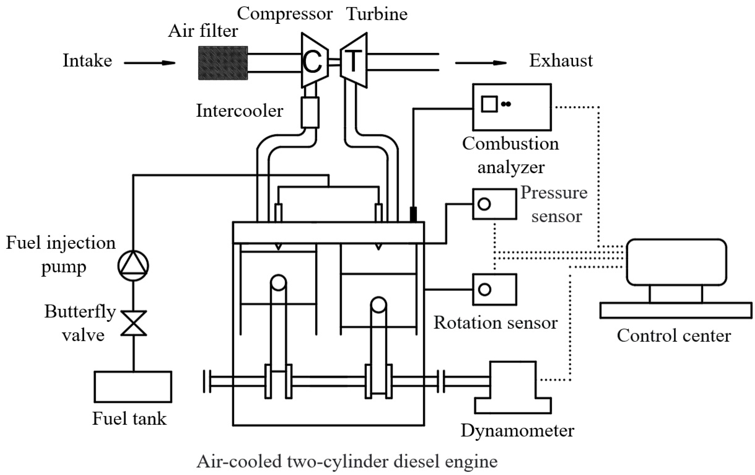
2.1. Experimental Setup

Figure 1 shows the test bench diagram for the air-cooled two-cylinder turbocharged diesel in this study. The basic parameters of the engine can be seen in Table 1. The output end of the diesel engine is connected to a small electric dynamometer. The dynamometer is capable of providing a maximum speed of 3600 r/min and a maximum power of 22 kW. The JP60A turbocharger, whose compressor diameter and turbine diameter are 33 mm and 32 mm each, was used to improve the intake condition of the diesel engine. Other main equipment parameters and sensor measurement progress are shown in Table 2. The diesel engine is connected to the dynamometer by a cone structure of the output shaft, which is bolted to a steel platform with a damper. The signal of cylinder pressure was measured using the Kistler-6050A sensor with a test accuracy of ±0.3%, and combustion was analyzed using analyzer CA3004A21 with a measurement error of ±0.5%FS. The speed signal came from the speed sensor, and the speed signal was the magnetoelectric signal of 60-2, with a measurement error of ±1 rpm.

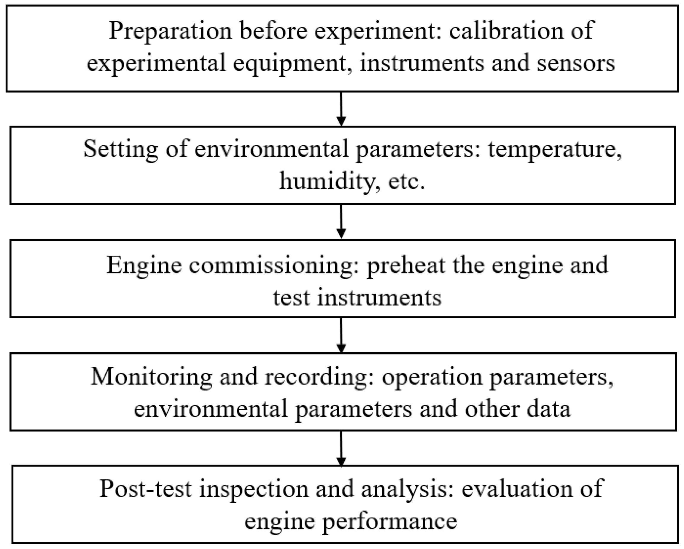
2.2. Experimental Procedures and Key Parameters

The experimental object was an air-cooled two-cylinder diesel engine for power generation. During the test, a dynamometer was used to control the engine test conditions, including engine speed and load, according to the “Limits and measurement methods for non-road diesel engine specific fuel consumption” (GB/T 28239-2020) [31], which were arranged as shown in Table 3. In each experimental condition in this test, the engine speed was fixed at 3000 r/min based on the requirement of generator sets. In order to improve the measurement precision of results, the experimental data were recorded after 10 min of stable operation, and the results of engine combustion characteristics were calculated and averaged according to 200 consecutive cycles. Moreover, the experimental boundary conditions were strictly controlled, as presented in Table 4.
Figure 2 is depicted to help explain the experiment approach of this study. Before the experiment, the sensor and measuring instrument were calibrated to ensure the accuracy and reliability of the test data. Also, the consistency of environmental conditions was checked. Then, the engine and test instruments were preheated. The test data were measured and recorded after the engine ran stably for ten minutes at least. Finally, the engine combustion performance could be evaluated by analyzing the test data. Regarding the experiment, the first step was to analyze the effects of the combustion chamber shape, as a properly designed shape is very beneficial to enhance the mixing of diesel and air by forming eddy currents [32]. As shown in Figure 3, the Modified Combustion Chamber (MCC) is deeper and wider than the original Standard Combustion Chamber (SCC). The diameter of the combustion chamber was increased from 48.7 mm to 50 mm and the depth from 12.5 mm to 14 mm, which increased the volume of the combustion chamber. In order to keep the combustion volume unchanged, the diameter of the taper was reduced from 46.4 mm to 43.8 mm. Moreover, the radius and dip angle of the pits became larger, while the shrink was smaller. At the same time, the curve of the central convex of the MCC was smoother, and the appropriate cone angle made it easier for fuel and air to diffuse and mix. Meanwhile, the engine compression ratio and fuel injection timing were fixed at 19.5 and −17 °CA, respectively.
In the second step of the experiment, the effects of the compression ratio of 18.5, 19.5 and 20.5 were studied. Meanwhile, the chamber is MCC, and the injection timing was kept at 17 °CA. Then, in the third step, the effects of injection timing conditions of −20 °CA, −15 °CA, −13 °CA, −10 °CA and −5 °CA were investigated under the conditions of MCC and 19.5 compression ratio.

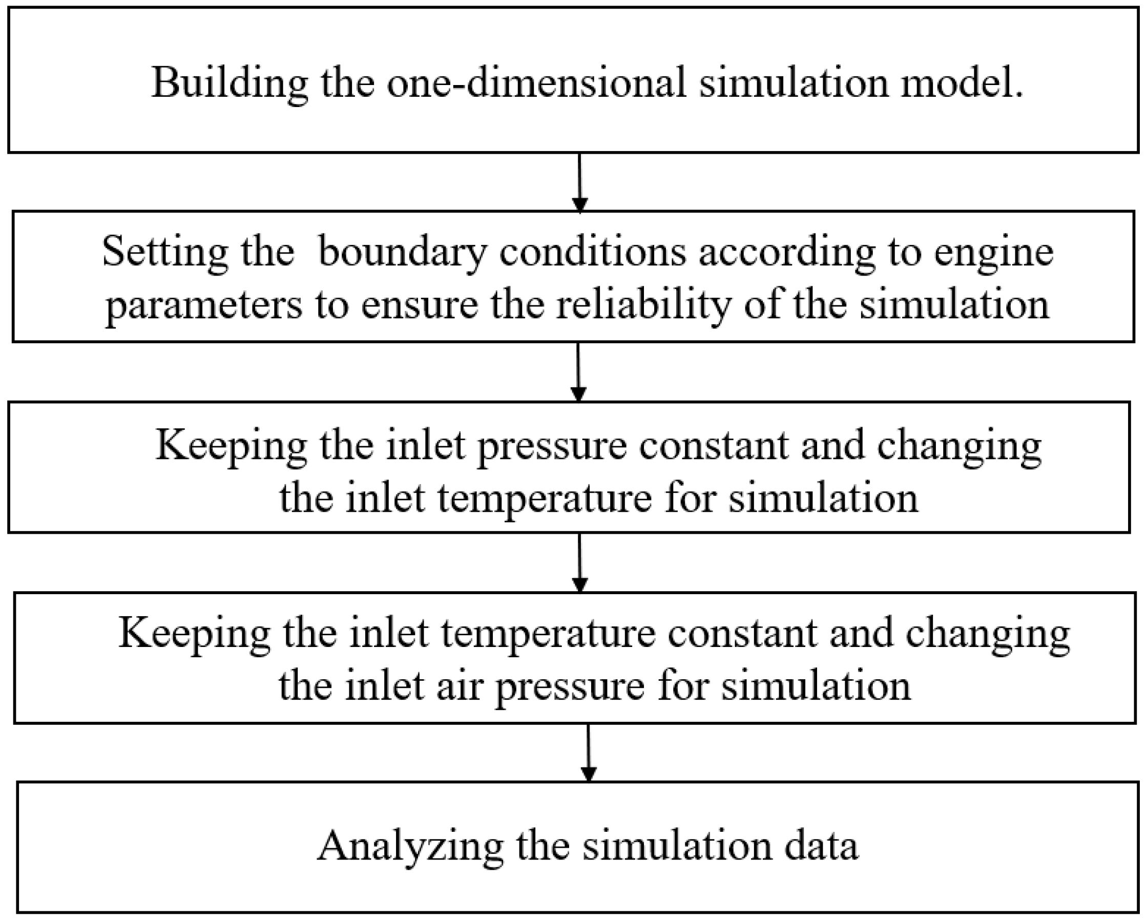
2.3. Simulation Procedures and Key Parameters

To further investigate the combustion performance of the engine, a one-dimensional simulation model was used to conduct simulation works for the engine. Figure 4 shows the flowchart of the simulation approach, and Figure 5 is a simplified schematic diagram of the one-dimensional simulation model. Firstly, a one-dimensional simulation model was built according to the experimental bench of Figure 1. The model parameters of the engine specifications and boundary conditions were set according to the details in Table 1 and Table 4. Then, the intake pressure was set to 0.1 MPa, and the effects of intake temperature from 230 K to 330 K with intervals of 20 K were simulated. Finally, the intake air temperature was kept at 280 K, and the effects of intake air pressure from 0.1 MPa to 0.06 MPa were numerically studied.
Various engine intake air conditions were quantitively studied, including extreme temperatures and different intake pressure. The key combustion parameters, including maximum cylinder pressure ( P M ), maximum cylinder temperature ( T M ), the crank angle (CA) of maximum cylinder pressure ( φ P m a x ) and the CA of maximum cylinder temperature ( φ T m a x ), were systematically analyzed.
The combustion process of a diesel engine includes the ignition delay period, the combustion duration period and the post-combustion period, among which the ignition delay affects the uniformity of diesel fuel mixing. The more evenly the fuel and air mix, the more fully the combustion is, and then the combustion duration is shortened. However, shortening the combustion duration can easily increase the explosion pressure in the cylinder and reduce its durability. In this paper, CA10, CA50 and CA90 were the crankshaft rotation angle corresponding to 10%, 50% and 90% combustion processes, respectively. The period from the beginning of fuel injection to CA10 was taken as the ignition delay, and the crankshaft angle between CA10 and CA90 was defined as the combustion duration. Moreover, P M was introduced to denote the maximum in-cylinder pressure, and φ P m a x was defined as the crank angle of the P M . T M denotes maximum in-cylinder temperature, φ T m a x is defined as the crank angle of the T M .
The combustion process has an important effect on the performance of diesel engines, and the heat release rate is the key parameter in the combustion process [33]. The Wiebe combustion model is used to express the premixed combustion and diffusion combustion stages; Novaes et al. have shown that Wiebe function parameters have a direct effect not only on engine pressure and temperature but also on engine performance, and the combustion model is shown in Equation (1) [34]:
x b θ = λ 1 e x p a 1 θ θ 0 θ 1 m 1 + 1 + 1 λ 1 e x p a 2 θ θ 0 θ 2 m 2 + 1 ,
where x b θ denotes the percentage of total mass fraction burned, θ denotes the crank angle corresponding to the top dead center time, and θ 0 denotes the crank angle corresponding to the starting point of combustion. θ 1 and θ 2 denote the combustion duration of premixed combustion mode and diffusion combustion mode, respectively. m 1 and m 2 denote the form factor of the premixed combustion mode and diffusion combustion mode, respectively. a 1 and a 2 denote the efficiency parameters of premixed combustion mode and diffusion combustion mode, respectively. λ denotes the weight factor.
The heat release rate is determined by cylinder pressure data, which is generally used to observe the combustion and heat. Assuming that air and fuel form a uniform mixture in the cylinder and are under uniform temperature and pressure during combustion, the heat release rate is determined using Equation (2) [35]:
d Q = γ γ 1 P d V + 1 γ 1 V d P + d Q w ,
where d Q is the heat release rate (J/°CA), γ is the specific heat ratio, P is the cylinder pressure (Pa), V is the instantaneous volume of the cylinder, and d Q w is the heat transfer rate.
In the process of engine operation, the state of the working medium in the cylinder was represented by three parameters, p, T and m, which were controlled with the mass conservation equation, the energy conservation equation and the ideal gas state equation.
The mass conservation equation is the following:
d m d φ = d m B d φ + d m s d φ d m E d φ ,
where m s is the mass of gas in the cylinder, m E is the mass of gas discharged from the cylinder, and m B is the mass of fuel entering the cylinder.
The energy conservation equation is the following:
d ( m u ) d φ = d Q B d ϕ + d Q W d ϕ P d V d ϕ + h s d m s d ϕ + h E d m E d ϕ ,
where V is the working volume of the cylinder, m is the mass of the working medium, P is the transient pressure of the cylinder, h s and h E are the specific enthalpy of the working medium at the inlet and exhaust valves, Q B is the heat released by the fuel, and Q W is the heat of the cylinder.
The equation of the state of ideal gas is the following:
P V = m R T ,
where R is the gas constant, and T is the gas temperature in the cylinder.

3. Results and Discussion

In this study, the intake conditions, combustor shape, compression ratio and injection timing were chosen as the research conditions to study the influence of external environment and internal factors on combustion performance. In order to display the in-cylinder combustion process, cylinder pressure, heat release rate, ignition delay period and combustion duration were selected as the combustion characteristics parameters.

3.1. Simulation Model Verification

In order to verify the accuracy and reliability of the model before optimizing the engine, the cylinder pressure and heat release rate were verified at 100% of engine load, 3000 r/min and 18.5 compression ratio, as shown in Figure 6. Although the experimental results may have been affected by various environmental factors, the curves of the simulation and experimental results matched very well. Among them, the maximum value of the cylinder pressure curve corresponding to the simulation and the crankshaft angle corresponding to the maximum value were 3.3 °CA and 9.952 MPa each in the simulation, while the corresponding values in the experiment were 4.4 °CA and 9.874 MPa, respectively. The differences were 1.1 °CA and 0.077 MPa, respectively, with percentages of error of about 0.31% and 0.78%, and the difference was within the acceptable range. The maximum heat release rate and crank angle in the simulation were 23.16 J/CA and 7.7 °CA for each. Moreover, the corresponding values were 20.67 J/CA and 11.2 °CA, respectively. Hence, the accuracy of this simulation model was quite acceptable with reference to the model validations in some other research [36,37,38].

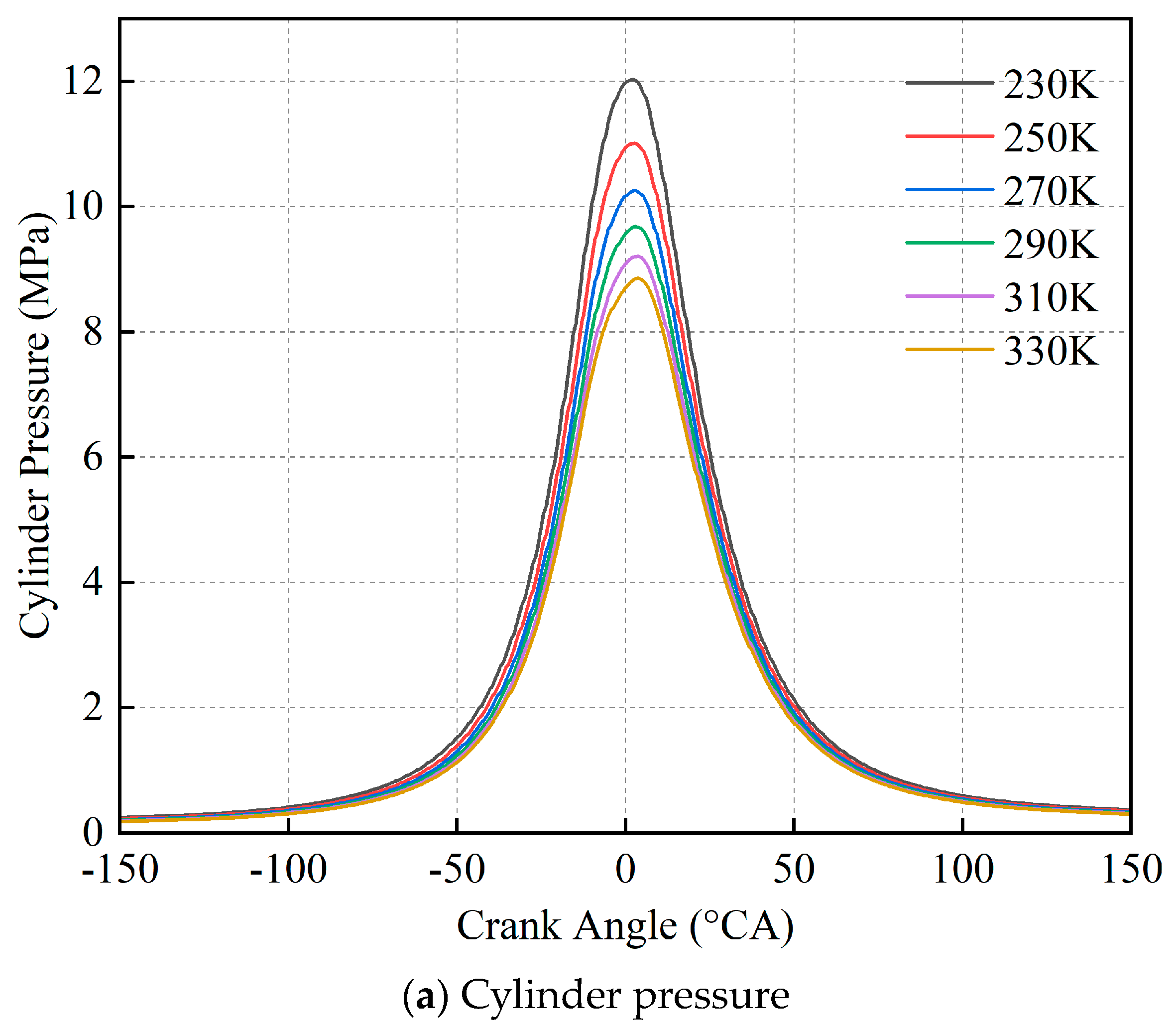
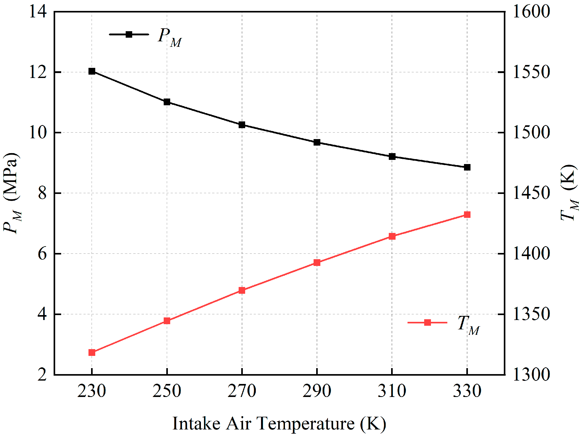
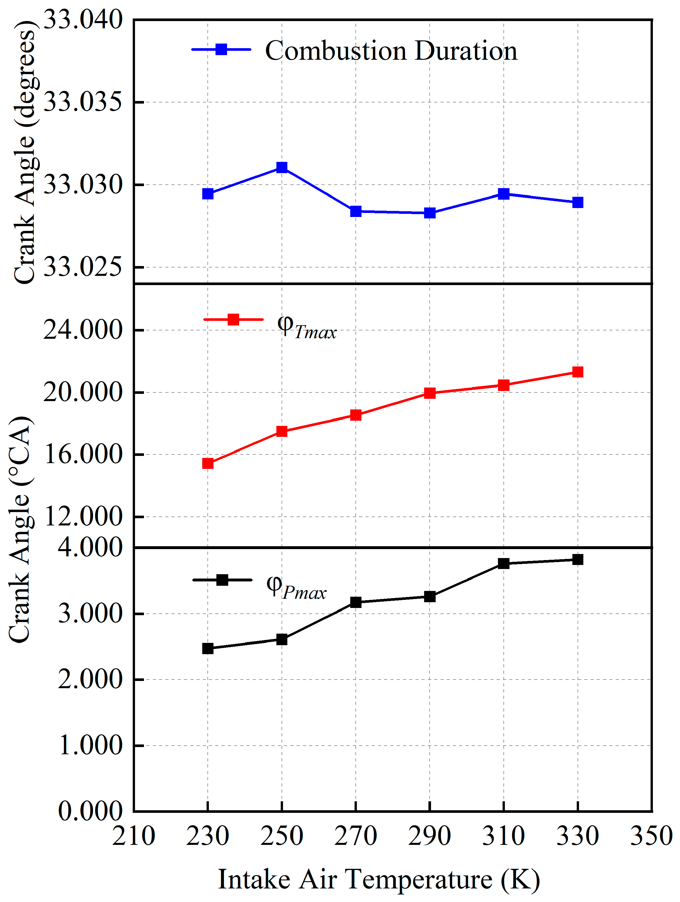
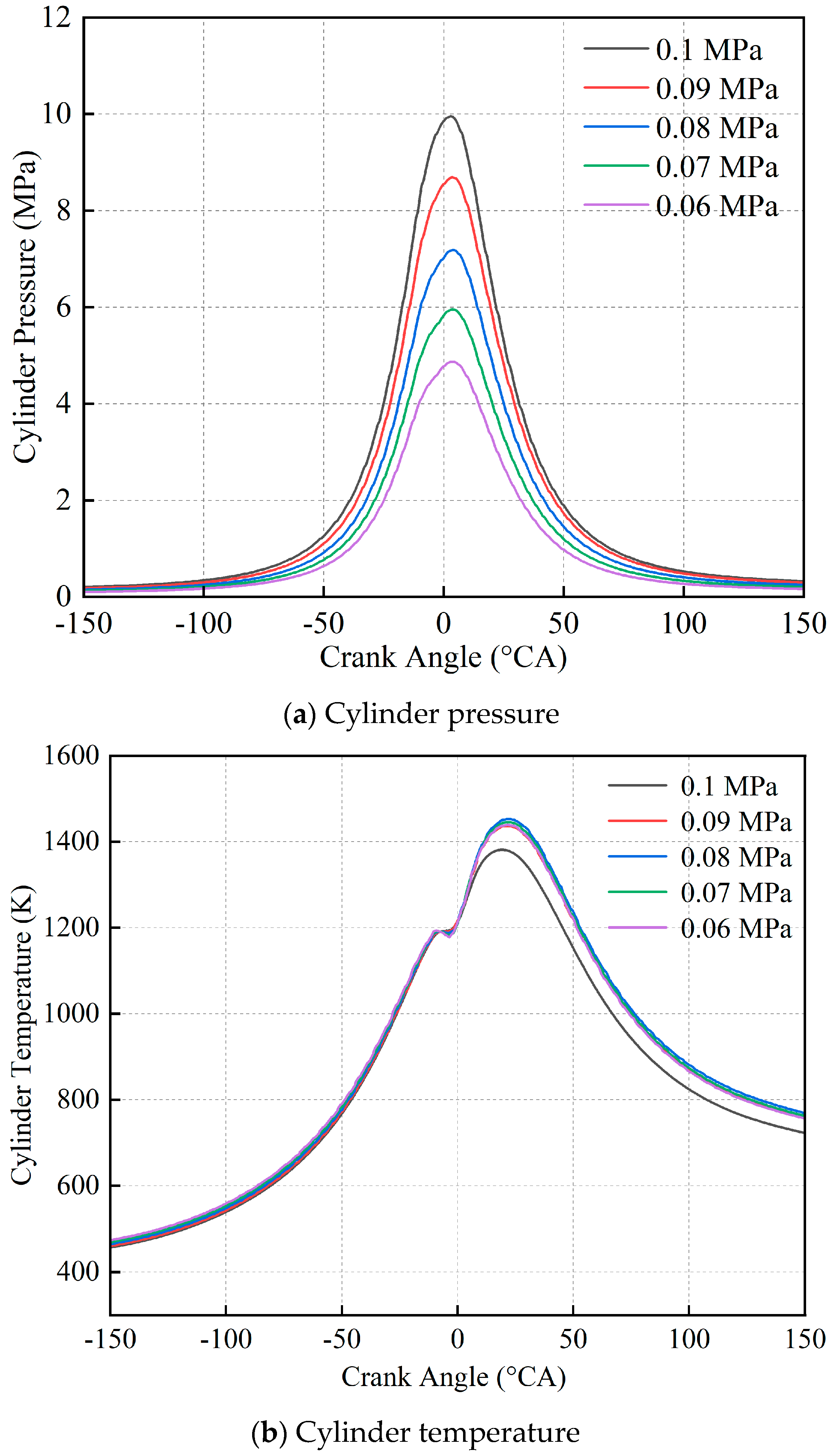
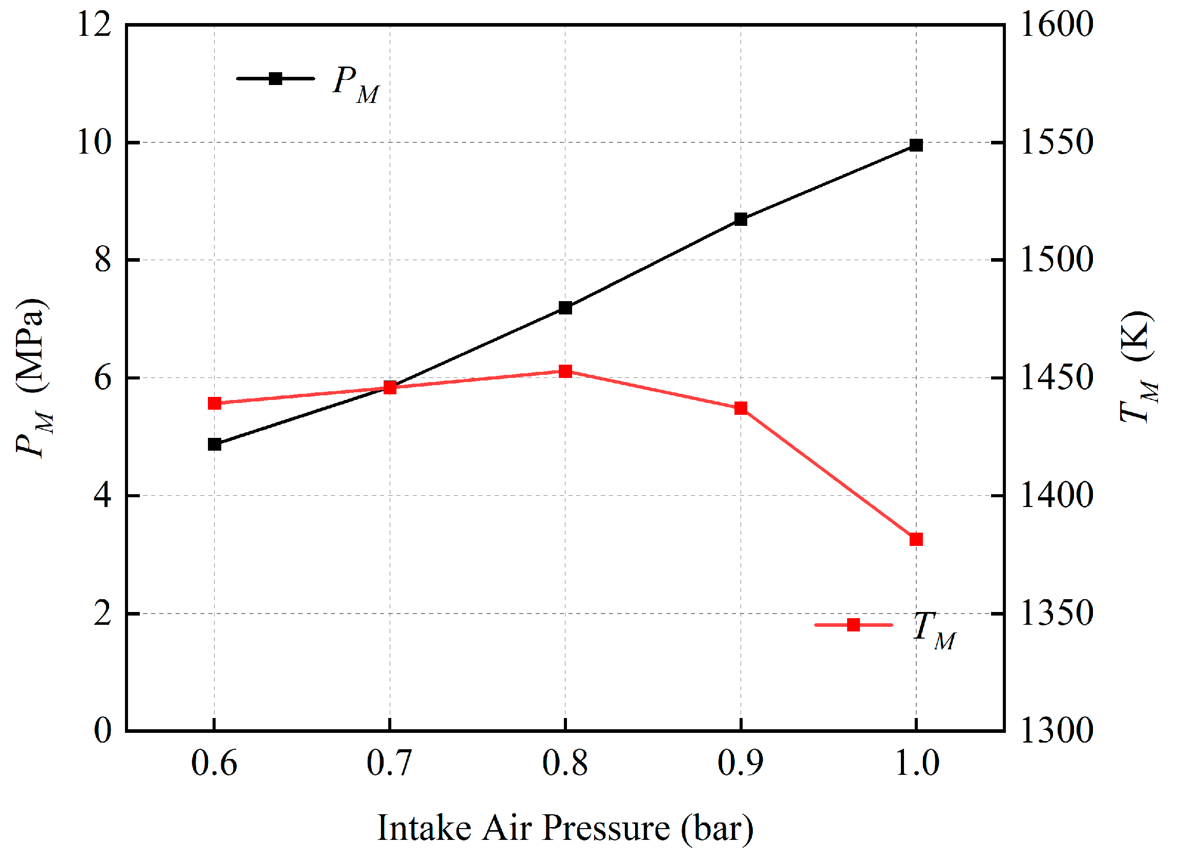
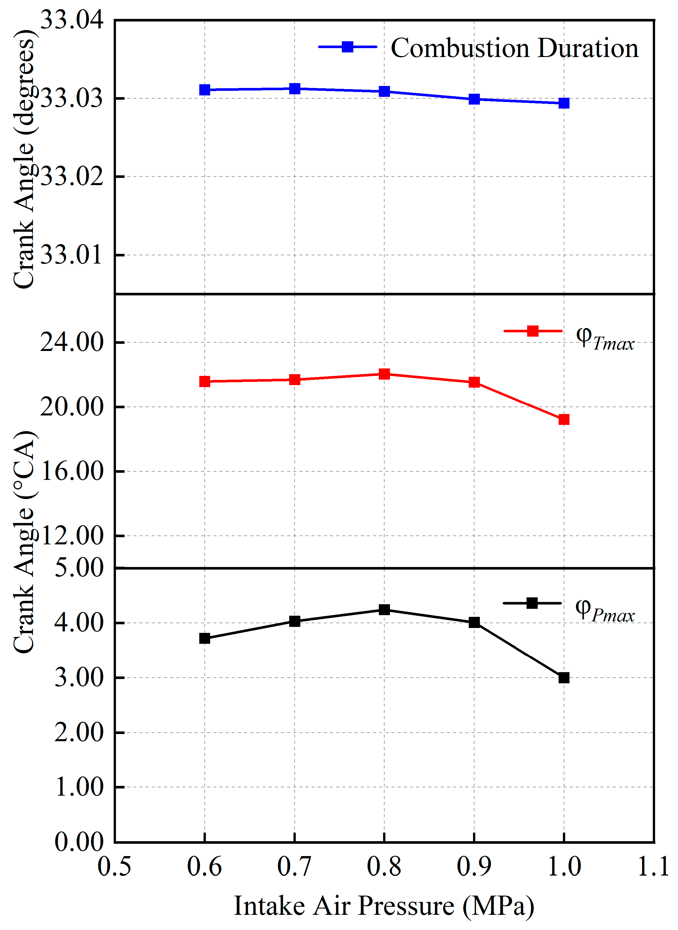
3.2. Effects of Intake Air Conditions

Figure 7 and Figure 8 mainly illustrate the effects of intake air temperature from 230 K to 330 K on cylinder pressure, cylinder temperature, P M and T M .
As shown in Figure 7a, the cylinder pressure showed a downward trend with the increase in intake air temperature. It can be found in Figure 8 that when the intake air temperature was 230 K and 270 K, P M could reach 12.03 MPa and 10.26 MPa, respectively. However, by increasing the intake air temperature to 330 K, P M was reduced to only 8.86 MPa. With every 20 K increase in intake air temperature, the gap between the P M of adjacent curves became smaller: 1.02 MPa, 0.75 MPa, 0.58 MPa, 0.47 MPa and 0.35 MPa, respectively.
Figure 7b shows the cylinder temperature curves under different intake air temperatures. Consequently, the overall development process of cylinder temperature can be beneficial. As can be seen from Figure 8, with the increase in intake air temperature, T M also gradually increased, but the increased range obviously decreased. Moreover, from 230 K to 250 K, T M increased by 26 K, while the 310 K to 330 K value increased by 18 K, which is consistent with the change law of the P M . However, the intake air density could be significantly reduced under high intake air temperature conditions. Hence, the heat release rate would be diminished due to decreased oxygen amount during combustion.
Figure 9 shows the effects of intake air temperature on combustion duration, φ P m a x and φ T m a x . Regarding combustion duration, the values were relatively similar across different intake air temperatures, implying that the overall change in combustion heat release was not substantial. In the meantime, with the intake air temperature increase from 230 K to 330 K, φ P m a x and φ T m a x delayed by 1.35 °CA and 5.89 °CA, respectively. Hence, the combustion center of gravity shifts rearward, improving the combustion performance.
Under actual working conditions, intake air pressure would gradually reduce with the increase in altitude. Figure 10a shows that the cylinder pressure curves under different intake air pressures. In the meantime, the intake air temperature was fixed at 280 K.
Unlike the effects of intake air temperatures, the cylinder pressure shows a consistent trend with the change of intake air pressure. With the decrease in intake air pressure from 0.1 MPa to 0.06 MPa, the cylinder pressure also gradually decreased. As shown in Figure 11, P M could reach 9.95 MPa at 1 bar intake air pressure, but it was only 4.84 MPa at 0.06 MPa. This is mainly because that a lower intake pressure, corresponding to a higher altitude, would deteriorate both intake air amount and combustion performance, reducing cylinder pressure.
Figure 10b shows the cylinder temperature curves under different intake air pressures. At the macro level, the cylinder temperature shows an upward trend by decreasing intake air pressure from 0.1 MPa to 0.09 MPa. It can also be seen that the corresponding T M in Figure 11 increases from 1381.4 K to 1437.1 K. This is mainly because by decreasing intake air pressure, the reduction of intake oxygen amount could adversely affect the heat release rate, leading to a prolonged combustion period with a higher cylinder temperature. Then, by further decreasing intake air pressure from 0.09 MPa to 0.06 MPa, the variation of cylinder temperature generally shows a stable trend. The corresponding T M ranges from a relatively narrow interval around 1445 K. That can be attributed to a combined effect of two main factors. First, the lower oxygen amount could extend the combustion process, benefiting the cylinder temperature. Second, reducing the oxygen amount would deteriorate the combustion performance, suppressing the upward trend of cylinder temperature.
Figure 12 shows the effects of intake air pressure on combustion duration, φ P m a x and φ T m a x .
The variation in combustion duration between different intake pressures was very slight. By decreasing intake air pressure from 0.1 MPa to 0.06 MPa, φ P m a x and φ T m a x first postpone, then became relatively stable. It indicates that with the decrease in intake air pressure, although the combustion duration is not apparently affected, the reduced oxygen amount still has the potential to prolong the whole combustion process, delaying the peak of cylinder pressure and temperature.

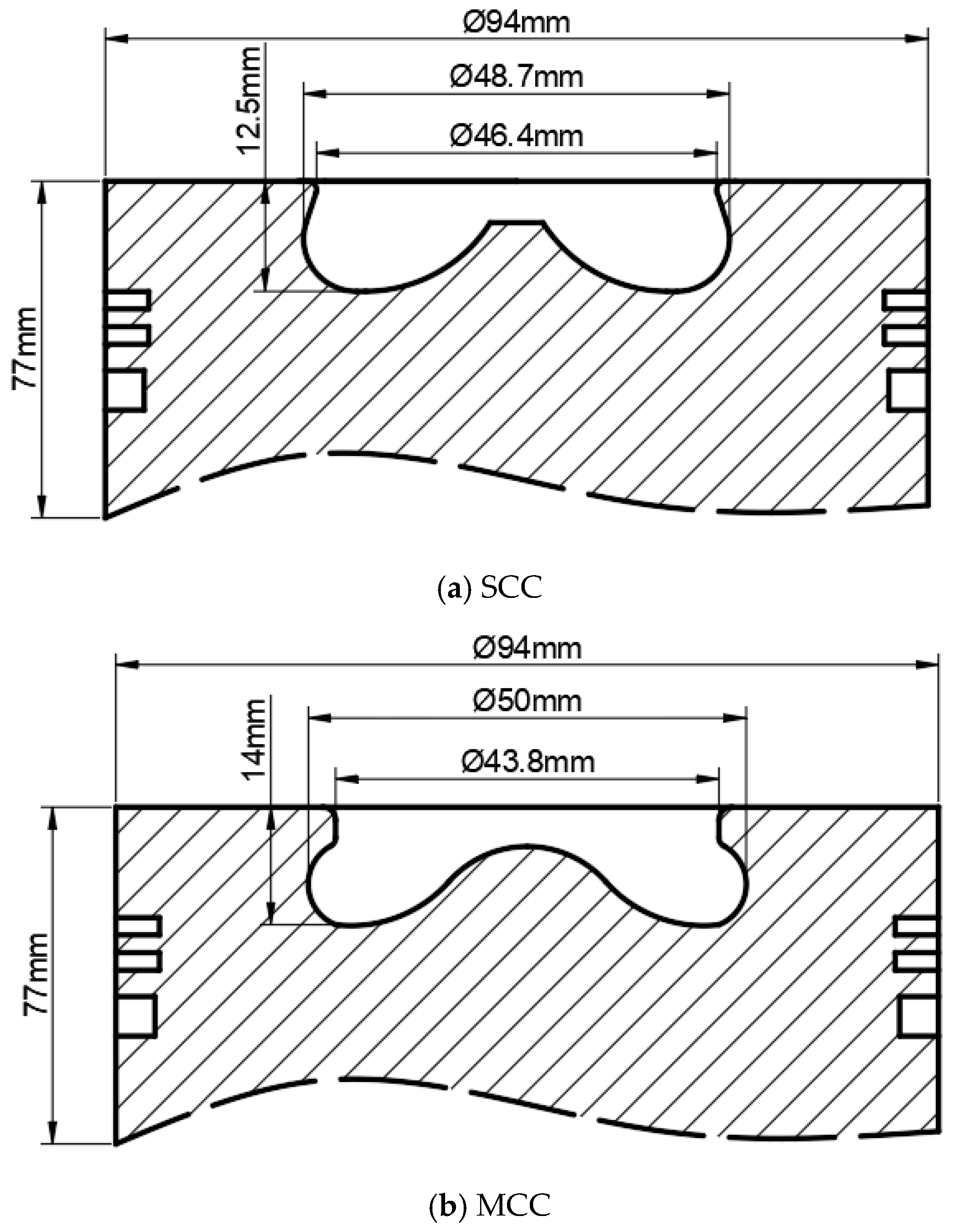
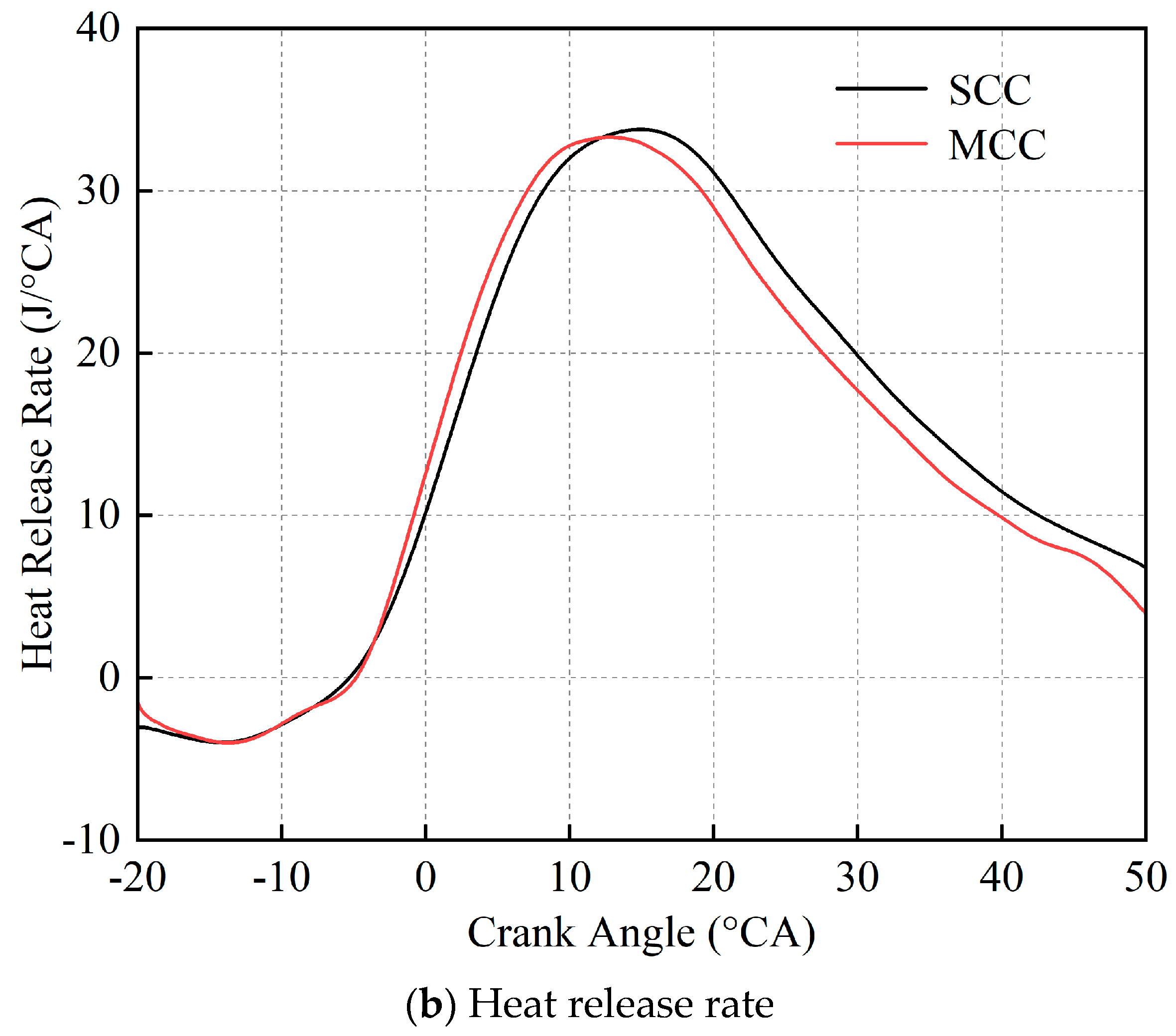
3.3. Effects of Combustion Chamber Shape

Figure 13a shows the effects of two combustion chamber structures on cylinder pressure under 100% engine load. It can be seen that the maximum cylinder pressure of the MCC condition is 0.22 MPa lower than that of SCC. This is mainly because, in the premixed combustion and diffusion combustion period, a wider and deeper chamber is helpful to promote the form of eddy currents, enhancing the fuel spray atomization. As can be seen from the heat release rate curve in Figure 13b, due to the rapid formation of the mixture in the MCC and the advance of premixed combustion, the concentrated heat release was earlier than the SCC, the heat release center moved forward, the cylinder pressure reached the peak in advance, and the heat load of the diesel engine was reduced. The decreasing released heat and pressure is helpful to reduce the entire engine’s heat load, enhancing the engine’s durability.
Figure 14 presents the comparison of the ignition delay and combustion duration between the SCC and MCC. It can be seen that, compared with the SCC condition, the ignition delay and combustion duration for MCC under 100% load are extended by about 1.6 degrees and 4.2 degrees, respectively. Under 75% load, the ignition delay extended around 1.6 degrees, but the combustion duration was almost the same. Regarding lower engine loads (25% and 50%), the ignition delay and combustion duration are not apparently affected by modifying the combustion chamber shape.

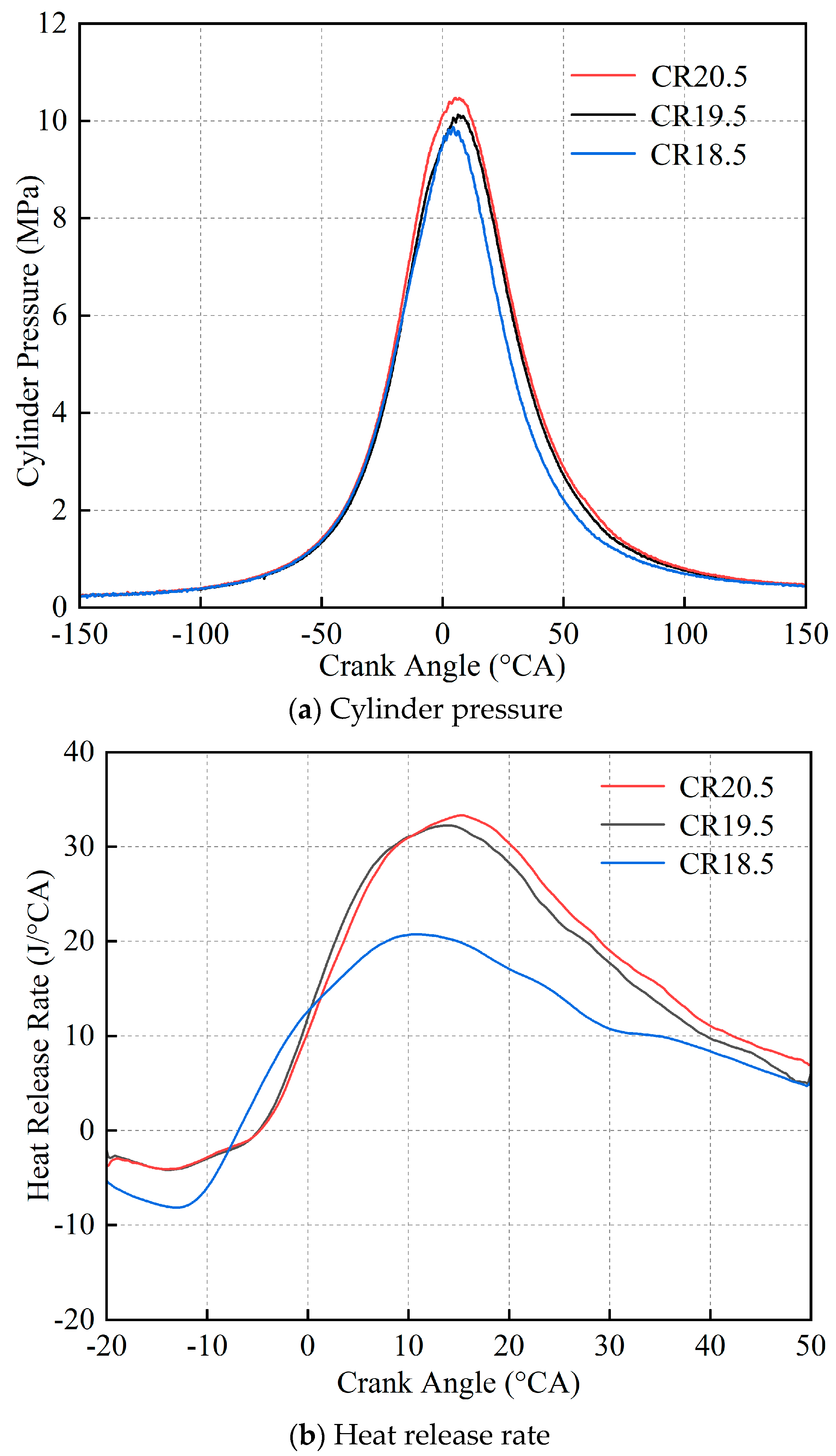
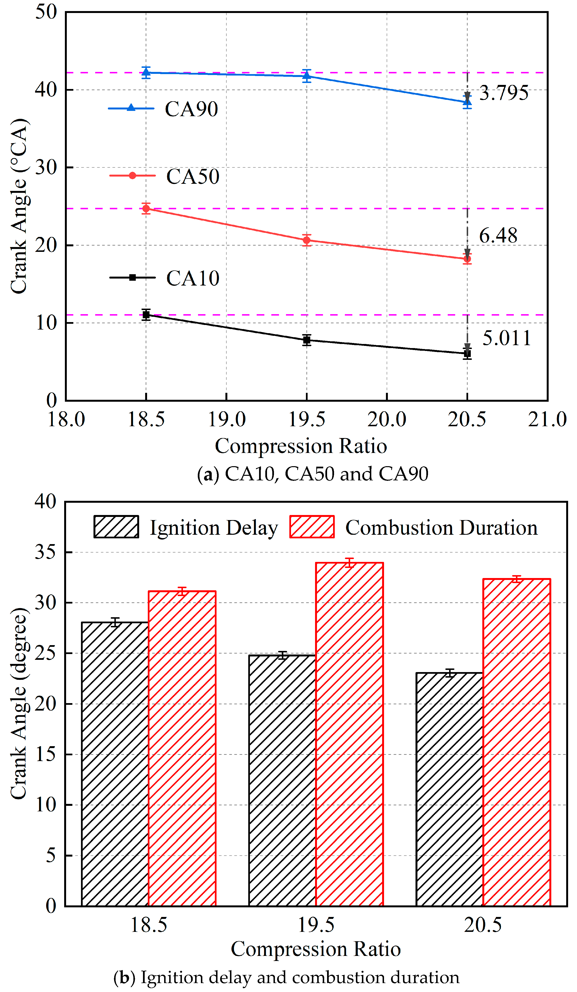
3.4. Effects of Compression Ratio

Figure 15 presents the results of cylinder pressure and heat release rate under different compression ratios under 100% engine load. Overall, it can be seen that a higher compression ratio would be beneficial to increase the cylinder pressure [39]. The pressure curve’s peak grew from 9.87 MPa to 10.47 MPa by increasing the compression ratio from 18.5 to 20.5. Regarding the heat release rate, under the condition of the 18.5 compression ratio, the combustion situation became worse, and the heat release rate was far less than the other two curves. Comparing the conditions between 19.5 and 20.5 compression ratios, there was no obvious change in the heat release rate curve. This is mainly because the corresponding compression clearance height is reduced as the compression ratio increases. Hence, when the piston approaches TDC, the cylinder pressure rises sharply, and the pressure difference of different compression ratios also expands. The temperature and pressure of the mixed gas in the combustion chamber could further increase at the end of the compression stroke.
Figure 16 presents the comparison of the combustion period under three compression ratio conditions. With the increase in compression ratio, all three kinds of periods (CA10, CA50 and CA90) are advanced on the whole. Compared with the 18.5 compression ratio, CA10 under the conditions of 19.5 and 20.5 compression ratios advanced by 3.3 °CA and 5 °CA, respectively. Meanwhile, CA50 and CA90 could each advance by around 6.5 °CA and 3.8 °CA by increasing compression from 18.5 to 20.5. Figure 16 shows that the ignition delay can be shortened by increasing the compression ratio, leading to higher cylinder pressure and heat release rate. Moreover, the combustion duration remains relatively stable under different compression ratio conditions.

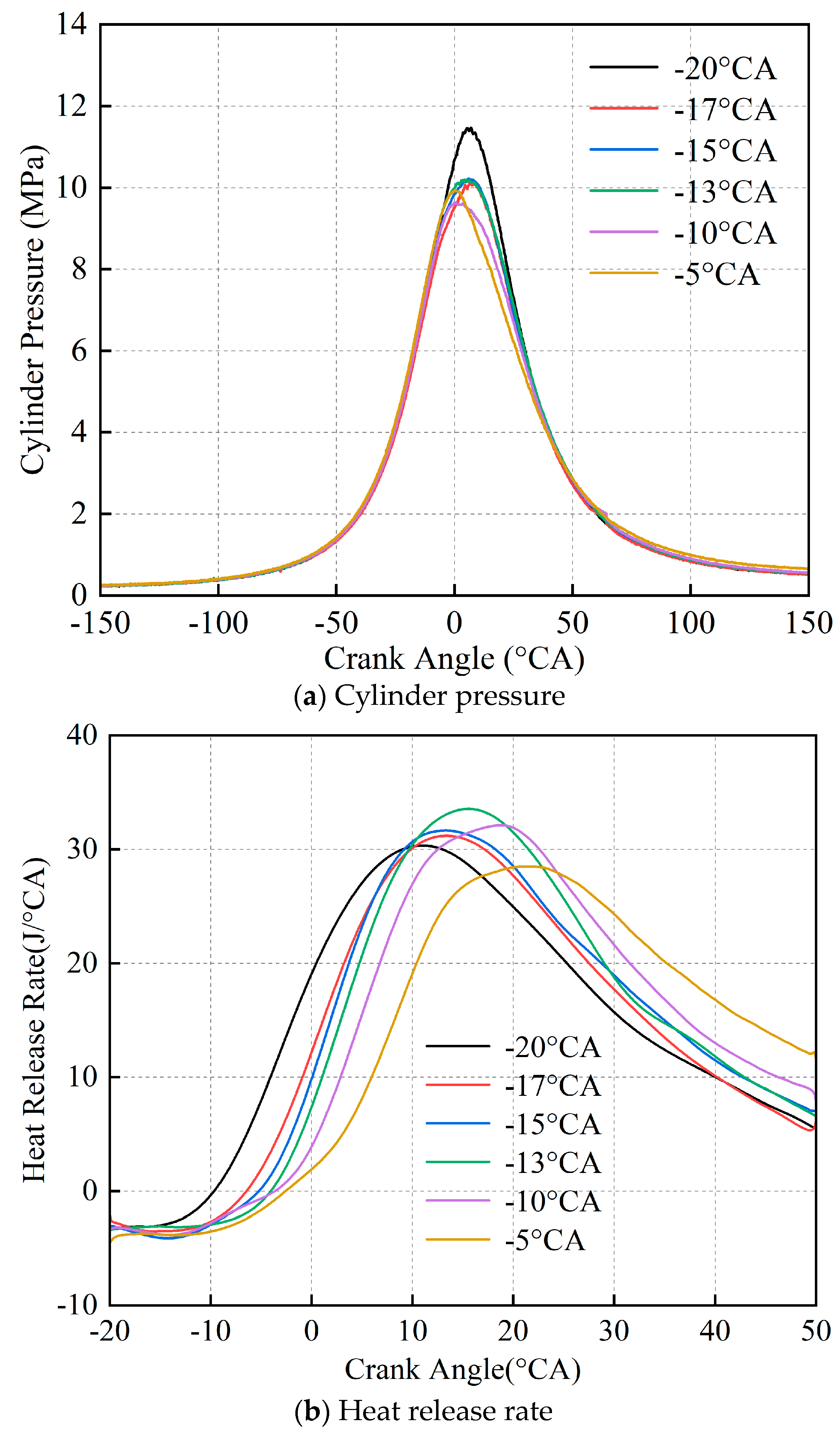
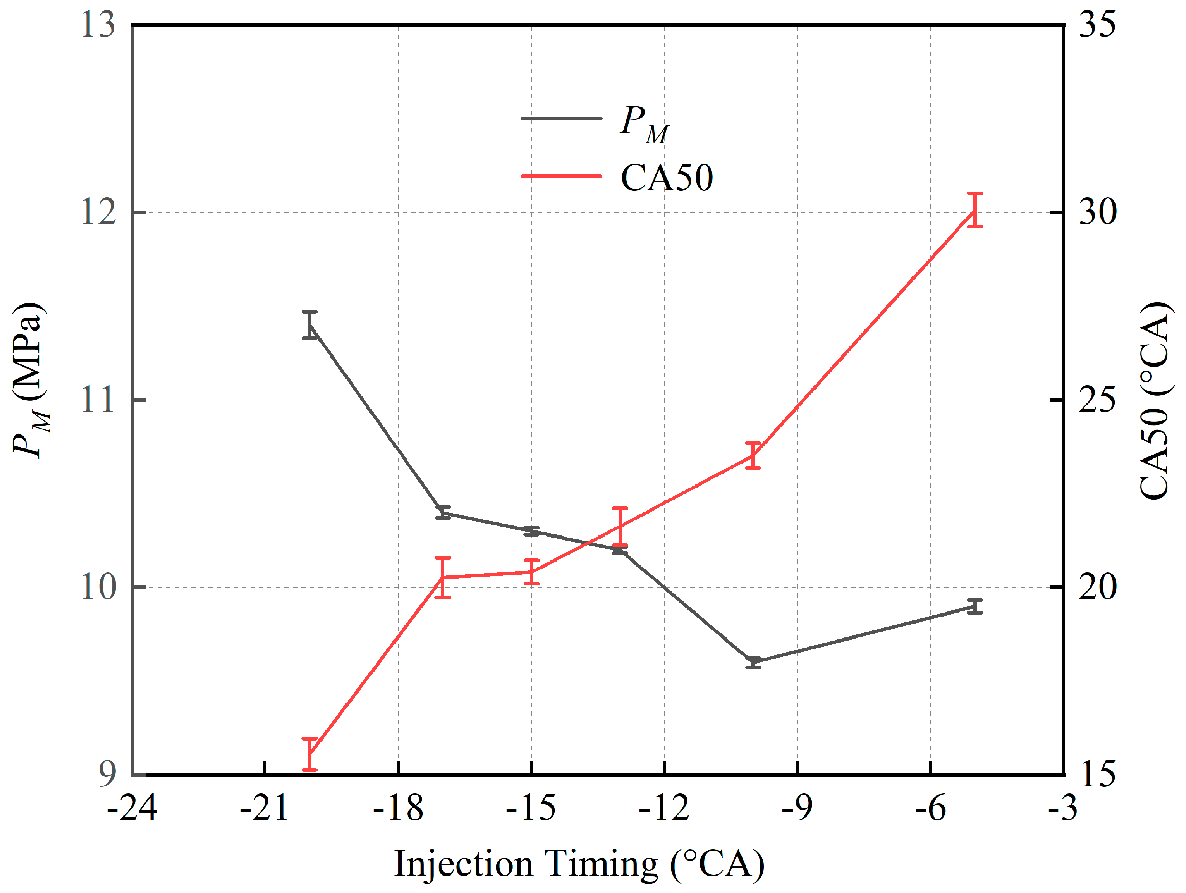
3.5. Effects of Injection Timing

Figure 17 to Figure 18 mainly present the effects of injection timing on cylinder pressure and heat release rate under 100% engine load. It can be found that with the advance of injection timing, the cylinder pressure generally shows an increasing trend in Figure 17a. P M could reach the maximum value of 11.4 MPa under the condition of −20 °CA injection timing, as shown in Figure 18. In addition, CA50 is delayed with the advance of injection timing, indicating that the center of gravity of combustion moves backward, which is conducive to full combustion and improving exergy efficiency [16,18].
By analyzing Figure 17b, it can be found that the distribution of heat release in the cylinder is relatively similar before the top dead center. This is mainly because advancing injection timing will help extend the ignition delay period, thus increasing the heat release proportion in the premixed combustion stage.
Figure 19 mainly shows the effects of injection timing on ignition delay and combustion duration under different loads. In Figure 19a, it can be seen that at 100% load, compared with the engine’s original injection timing of −17 °CA, the ignition delay period is shortened by 1.4 degrees when the injection timing is advanced to −20 °CA. With the further delay of injection timing from −17 °CA to −13 °CA, the ignition delay is shortened by 3.8 degrees, 3.87 degrees and 2.48 degrees for each under 100%, 75% and 50% loads, respectively.
Moreover, as presented in Figure 19b, with the delay of the injection timing, the extension of the combustion duration was conducive to the full combustion of the fuel. Significantly, under 100% load, compared with the engine’s original injection timing of −17 °CA, the combustion duration was extended by 12.24 degrees under −5 °CA injection timing. However, the excessive combustion duration may lead to higher vibration and noise, reducing the diesel engine’s durability. While under middle and low loads, especially 25% load, the combustion duration is less affected by injection timing.

4. Conclusions

In this study, the effects of the combustion chamber, compression ratio and injection timing on the combustion performance of a non-road air-cooled two-cylinder turbocharged diesel engine were studied. First, the effects of intake air conditions were numerically investigated. Then, using experimental methods, the combustion performance was studied by changing the shape of the combustion chamber, followed by exploring the effects of different compression ratios and injection timing based on the MCC. The main results can be summarized as follows:
(1) With the increase in intake air temperature from 230 K to 330 K, the cylinder pressure decreased, while T M gradually increased. In the meantime, φ P m a x and φ T m a x were each postponed by 1.35 °CA and 5.89 °CA, which would benefit the engine’s combustion performance.
(2) By reducing intake air pressure from 1 bar to 0.6 bar, combustion performance obviously deteriorated mainly due to the lower intake oxygen amount. P M had a marked decline from 9.95 MPa to 4.84 MPa, and T M had a small increase from 1381.4 K to 1437.1 K. φ P m a x and φ T m a x initially experienced a delay, followed by a relatively stable variation.
(3) After replacing SCC with MCC, cylinder pressure and heat release rate were reduced, which could benefit the engine’s durability due to lower heat load. Moreover, the ignition delay and combustion duration were each extended by 1.6 degrees and 4.2 degrees under 100% load. Under 75% load, there was a small extension of around 1.6 degrees for the ignition delay, and the combustion duration was almost the same. Under relatively low engine loads (25% and 50%), compared with the MCC condition, both ignition delay and combustion duration modifications remained largely unchanged under the SCC condition.
(4) Under 100% engine load, the effects of engine compression ratio were explored. By increasing the compression ratio from 18.5 to 20.5, the peak cylinder pressure rose from 9.87 MPa to 10.47 MPa. Compared with the 18.5 compression ratio condition, there was a marked improvement in heat release rate under higher compression ratios. Moreover, with the increase in compression ratio, CA10, CA50 and CA90 could be advanced, and the ignition delay could be shortened.
(5) By advancing injection timing to −20 °CA, the peak cylinder pressure could increase up to 11.4 MPa, and the ignition delay was shortened by 1.4 degrees under 100% load. By delaying the injection timing, the prolonged combustion duration facilitated the thorough combustion of the fuel. Particularly, under a 100% load, compared with the engine’s original injection timing of −17 °CA, the combustion duration extended by 12.24 degrees under a −5 °CA injection timing. Meanwhile, under middle and low loads, the effects of injection timing on combustion duration became quite weak.

Author Contributions

Conceptualization, X.Z.; methodology, P.N. and Y.F.; software, Y.D. and X.L.; validation, P.N. and X.Z.; formal analysis, Y.D.; investigation, Y.D.; resources, X.Z.; writing—original draft preparation, Y.D.; writing—review and editing, Y.D. and X.L.; visualization, Y.D.; supervision, X.Y. and P.N.; project administration, X.Z.; funding acquisition, X.Z. All authors have read and agreed to the published version of the manuscript.

Funding

This work was supported by the Nantong Science and Technology Project for People’s Livelihood (No. MS22022036) and the National Key Research and Development Program of China (No. 2017YFE0116100).

Institutional Review Board Statement

Not applicable.

Informed Consent Statement

Not applicable.

Data Availability Statement

No new data were created or analyzed in this study. Data sharing is not applicable to this article.

Conflicts of Interest

The authors declare no conflicts of interest.

References

  1. Shi, X.C.; Liu, B.L.; Zhang, C.; Hu, J.C.; Zeng, Q.Q. A study on combined effect of high EGR rate and biodiesel on combustion and emission performance of a diesel engine. Appl. Therm. Eng. 2017, 125, 1272–1279. [Google Scholar] [CrossRef]
  2. Feng, R.; Chen, K.; Sun, Z.W.; Hu, X.L.; Li, G.H.; Wang, S. A comparative study on the energy flow of a hybrid heavy truck between AMT and MT shift mode under local driving test cycle. Energy Convers. Manag. 2022, 256, 115359. [Google Scholar] [CrossRef]
  3. Singh, B.; Niwas, R. Fuel-efficient Induction Generator Based Diesel Generator Set for Stand-alone Supply Systems. Electr. Power Compon. Syst. 2015, 43, 2019–2028. [Google Scholar] [CrossRef]
  4. Marqusee, J.; Don, D.J., II. Reliability of emergency and standby diesel generators: Impact on energy resiliency solutions. Appl. Energy 2020, 268, 114918. [Google Scholar] [CrossRef]
  5. Knudsen, J.; Bendtsen, J.D.; Andersen, P.; Madsen, K.K.; Sterregaard, C.H. Supervisory control implementation on diesel-driven generator sets. IEEE Trans. Ind. Electron. 2018, 65, 9698–9705. [Google Scholar] [CrossRef]
  6. Wu, Q.; Liang, X.; Zhu, Z.; Cui, L.; Liu, T. Numerical Simulation Research on Combustion and Emission Characteristics of Diesel/Ammonia Dual-Fuel Low-Speed Marine Engine. Energies 2024, 17, 2960. [Google Scholar] [CrossRef]
  7. Visan, N.A.; Niculescu, D.C.; Ionescu, R.; Dahlin, E.; Eriksson, M.; Chiriac, R. Study of Effects on Performances and Emissions of a Large Marine Diesel Engine Partially Fuelled with Biodiesel B20 and Methanol. J. Mar. Sci. Eng. 2024, 12, 952. [Google Scholar] [CrossRef]
  8. Ding, Y.; Sui, C.; Li, J. An experimental investigation into combustion fitting in a direct injection marine diesel engine. Appl. Sci. 2018, 8, 2489. [Google Scholar] [CrossRef]
  9. Saad, S.M.; Mishra, R. Performance of a heavy-duty turbocharged diesel engine under the effect of air injection at intake manifold during transient operations. Arab. J. Sci. Eng. 2019, 44, 5863–5875. [Google Scholar] [CrossRef]
  10. Carlucci, A.P.; Ficarella, A.; Trullo, G. Performance optimization of a two-stroke supercharged diesel engine for aircraft propulsion. Energy Convers. Manag. 2016, 122, 279–289. [Google Scholar] [CrossRef]
  11. Taghavifar, H.; Nemati, A.; Salvador, F.; De la Morena, J. 1D energy, exergy, and performance assessment of turbocharged diesel/hydrogen RCCI engine at different levels of diesel, hydrogen, compressor pressure ratio, and combustion duration. Int. J. Hydrogen Energy 2021, 46, 22180–22194. [Google Scholar] [CrossRef]
  12. Liu, X.; Zeng, L.; Li, X.; Chen, X.; Su, H. Thermodynamic analysis of cogeneration system with diesel engines for offshore oil production facilities under variable loads. Energy Sources Part A Recovery Util. Environ. Eff. 2020, 1–16. [Google Scholar] [CrossRef]
  13. Annamalai, R.; Kuppusamy, R.; Krishnan, R.S. Effect of piston bowl geometry and different injection pressure on the performance, emission and combustion characteristics of diesel engine using biodiesel blend. Therm. Sci. 2018, 22, 1445–1456. [Google Scholar] [CrossRef]
  14. Singh, B.; Shukla, S.K. Experimental analysis of combustion characteristics on a variable compression ratio engine fuelled with biodiesel (castor oil) and diesel blends. Biofuels 2016, 7, 471–477. [Google Scholar] [CrossRef]
  15. Menacer, B. The convection heat transfer rate evaluation of a 6-cylinder in-line turbocharged direct-injection diesel engine. Mechanics 2017, 23, 528–536. [Google Scholar] [CrossRef]
  16. Liu, C.; Liu, Z.; Tian, J.; Han, Y.; Xu, Y.; Yang, Z. Comprehensive investigation of injection parameters effect on a turbocharged diesel engine based on detailed exergy analysis. Appl. Therm. Eng. 2019, 154, 343–357. [Google Scholar] [CrossRef]
  17. Pehlivan, E.F.; Altin, I. Exergy analysis under consideration of operational parameters by numerical approach in a two-stroke marine diesel engine. Fuel 2024, 368, 131650. [Google Scholar] [CrossRef]
  18. Li, Y.; Zhang, C.; Yu, W.; Wu, H. Effects of rapid burning characteristics on the vibration of a common-rail diesel engine fueled with diesel–methanol dual-fuel. Fuel 2016, 170, 176–184. [Google Scholar] [CrossRef]
  19. Huang, R.; Ni, J.; Wang, Q.; Shi, X.; Yin, Q. Experimental and Mechanism Study of Aerodynamic Noise Emission Characteristics from a Turbocharger Compressor of Heavy-Duty Diesel Engine Based on Full Operating Range. Sustainability 2023, 15, 11300. [Google Scholar] [CrossRef]
  20. Zammit, J.-P.; McGhee, M.J.; Shayler, P.J.; Pegg, I. The influence of cylinder deactivation on the emissions and fuel economy of a four-cylinder direct-injection diesel engine. Proc. Inst. Mech. Eng. Part D J. Automob. Eng. 2014, 228, 206–217. [Google Scholar] [CrossRef]
  21. Wu, L.; Fu, J.; Ma, Y.; Xie, D. The Performance of an Air-Cooled Diesel Engine with a Variable Cross-Section Dual-Channel Swirl Chamber. Energies 2022, 15, 7263. [Google Scholar] [CrossRef]
  22. Singh, A.P.; Agarwal, A.K. Partially homogenous charge compression ignition engine development for low volatility fuels. Energy Fuels 2017, 31, 3164–3181. [Google Scholar] [CrossRef]
  23. Ni, P.; Xu, H.; Zhang, Z.; Zhang, X. Effect of injector nozzle parameters on fuel consumption and soot emission of two-cylinder diesel engine for vehicle. Case Stud. Therm. Eng. 2022, 34, 101981. [Google Scholar] [CrossRef]
  24. Ju, K.; Kim, J.; Park, J. Numerical prediction of the performance and emission of downsized two-cylinder diesel engine for range extender considering high boosting, heavy exhaust gas recirculation, and advanced injection timing. Fuel 2021, 302, 121216. [Google Scholar] [CrossRef]
  25. Pan, W.; Yao, C.; Han, G.; Wei, H.; Wang, Q. The impact of intake air temperature on performance and exhaust emissions of a diesel methanol dual fuel engine. Fuel 2015, 162, 101–110. [Google Scholar] [CrossRef]
  26. Lee, S.; Choi, W.; Kim, C.; Lee, S.; Oh, S.; Lee, J. Effects of Overall-equivalence Ratios by Varying Intake Pressures and Exhaust Gas Recirculation Rates on the Natural Gas/Diesel Dual-fuel Combustion at a High Load Condition. Int. J. Automot. Technol. 2022, 23, 149–158. [Google Scholar] [CrossRef]
  27. Silva, E.; Ochoa, A.; Henríquez, J. Analysis and runners length optimization of the intake manifold of a 4-cylinder spark ignition engine. Energy Convers. Manag. 2019, 188, 310–320. [Google Scholar] [CrossRef]
  28. Bogdanowicz, E.F.; Bittle, J.A.; Agrawal, A.K. Numerical investigation of peripheral fuel injection to increase performance in diesel engines. Fuel 2024, 371, 131895. [Google Scholar] [CrossRef]
  29. Lee, C.Y.; Vo, D.Q. Influence of cold-start time reduction on scooter emissions and fuel consumption over WMTC cycle. Energy 2021, 231, 120997. [Google Scholar] [CrossRef]
  30. Heywood, J.B. Internal Combustion Engine Fundamentals, 2nd ed.; McGraw-Hill: New York, NY, USA, 2018. [Google Scholar]
  31. Feng, R.; Hu, X.; Li, G.; Sun, Z.; Ye, M.; Deng, B. Exploration on the emissions and catalytic reactors interactions of a non-road diesel engine through experiment and system level simulation. Fuel 2023, 342, 127746. [Google Scholar]
  32. Ni, P.Y.; Wang, X.L.; Li, H. A review on regulations, current status, effects and reduction strategies of emissions for marine diesel engines. Fuel 2020, 279, 118477. [Google Scholar] [CrossRef]
  33. Girtler, J. A semi-Markov model of fuel combustion process in a Diesel engine. Pol. Marit. Res. 2007, 14, 58–61. [Google Scholar]
  34. Yang, R.; Ran, Z.; Hadlich, R.R.; Assanis, D. A Double-Wiebe Function for Reactivity Controlled Compression Ignition Combustion Using Reformate Diesel. J. Energy Resour. Technol. 2022, 144, 112301. [Google Scholar] [CrossRef]
  35. Yilmaz, I.T.; Gumus, M. Investigation of the effect of biogas on combustion and emissions of TBC diesel engine. Fuel 2017, 188, 69–78. [Google Scholar] [CrossRef]
  36. Margot, X.; Quintero, P.; Gomez-Soriano, J.; Escalona, J. Implementation of 1D–3D integrated model for thermal prediction in internal combustion engines. Appl. Therm. Eng. 2021, 194, 117034. [Google Scholar] [CrossRef]
  37. Meng, X.; Zhao, C.; Cui, Z.; Zhang, X.; Zhang, M.; Tian, J.; Long, W.; Bi, M. Understanding of combustion characteristics and NO generation process with pure ammonia in the pre-chamber jet-induced ignition system. Fuel 2023, 331, 125743. [Google Scholar] [CrossRef]
  38. Duan, X.; Xu, Z.; Sun, X.; Deng, B.; Liu, J. Effects of injection timing and EGR on combustion and emissions characteristics of the diesel engine fuelled with acetone–butanol–ethanol/diesel blend fuels. Energy 2021, 231, 121069. [Google Scholar] [CrossRef]
  39. Kiplimo, R.; Tomita, E.; Kawahara, N.; Yokobe, S. Effects of compression ratio and simulated EGR on combustion characteristics and exhaust emissions of a diesel PCCI engine. J. Therm. Sci. Technol. 2011, 6, 463–474. [Google Scholar] [CrossRef]
Figure 1. Schematic diagram of the test bench.
Sustainability 16 06031 g001
Figure 2. Diagram of experiment approach.
Sustainability 16 06031 g002
Figure 3. Comparison of two combustion chamber shapes: (a) SCC and (b) MCC.
Sustainability 16 06031 g003
Figure 4. Diagram of simulation approach.
Sustainability 16 06031 g004
Figure 5. Simplified diagram of simulation model.
Sustainability 16 06031 g005
Figure 6. Comparison between simulation and experiment.
Sustainability 16 06031 g006
Figure 7. Effects of intake air temperature on cylinder pressure and cylinder temperature.
Sustainability 16 06031 g007aSustainability 16 06031 g007b
Figure 8. Effects of intake air temperature on P M and T M .
Sustainability 16 06031 g008
Figure 9. Effects of intake air temperature on combustion duration, φ P m a x and φ T m a x .
Sustainability 16 06031 g009
Figure 10. Effects of intake air pressure on cylinder pressure and cylinder temperature.
Sustainability 16 06031 g010
Figure 11. Effects of intake air pressure on P M , T M .
Sustainability 16 06031 g011
Figure 12. Effects of intake air pressure on combustion duration, φ P m a x and φ T m a x .
Sustainability 16 06031 g012
Figure 13. Effects of combustion chamber shape on cylinder pressure and heat release rate.
Sustainability 16 06031 g013aSustainability 16 06031 g013b
Figure 14. Effects of combustion chamber shape on ignition delay period and combustion duration.
Sustainability 16 06031 g014aSustainability 16 06031 g014b
Figure 15. Effects of compression ratio on cylinder pressure and heat release rate.
Sustainability 16 06031 g015
Figure 16. Effects of compression ratio on CA10, CA50, CA90, ignition delay and combustion duration.
Sustainability 16 06031 g016
Figure 17. Effects of injection timing on heat release rate.
Sustainability 16 06031 g017
Figure 18. Effects of injection timing on P M .
Sustainability 16 06031 g018
Figure 19. Effects of injection timing on ignition delay period and combustion duration.
Sustainability 16 06031 g019aSustainability 16 06031 g019b
Table 1. Basic parameters of original two-cylinder diesel engine.
Brand/ModelValue
TypeIn-line, turbocharged
Number of cylinders2
Bore Stroke (mm)94 × 77
Displacement (L)1.069
Compression ratio18.5
Rated revolution (rpm)3000
Rated power (kW)14
Maximum power (kW)15
Compression clearance height (mm)1.2
Fuel supply modePump-tube-nozzle
Table 2. Uncertainties and specifications of sensors and instrumentations.
Sensors/InstrumentationsModelUncertainties
Oil consumption meterFN-03±1%
Temperature sensorWRNK191±1%
Combustion analyzerCA3004A21±0.5%FS
Cylinder pressure sensorKistler-6050A±0.3%
Speed sensorM16 × 1.5±1 rpm
Oil pressure gaugeWHM5±2%
HygrometerSH002±1%
DynamometerWY-AC-16±0.1 kW
Table 3. Engine test conditions.
Serial NumberEngine SpeedPercent of Engine Load
13000 rpm100
23000 rpm75
33000 rpm50
43000 rpm25
53000 rpm0
Table 4. Boundary conditions in the test.
Boundary ConditionsRange
Fuel temperature (K)303 ± 5
Ambient temperature (K)298 ± 5
Pressure difference before and after intercooler (MPa)<0.002
Exhaust back pressure (MPa)<0.006
Exhaust temperature before turbine (K)<823
Disclaimer/Publisher’s Note: The statements, opinions and data contained in all publications are solely those of the individual author(s) and contributor(s) and not of MDPI and/or the editor(s). MDPI and/or the editor(s) disclaim responsibility for any injury to people or property resulting from any ideas, methods, instructions or products referred to in the content.

