Article

A Multi-Technique Hybrid Method for the Widening and Splicing of New and Old Beam Bridges

1
Hunan Provincial Communications Planning, Survey & Design Institute Co., Ltd., Changsha 410200, China
2
Qilu Traffic Qingdao Investment Development Limited Company, Qingdao 266061, China
3
School of Transportation Science and Engineering, Harbin Institute of Technology, 73 Huanghe Road, Harbin 150090, China
*
Author to whom correspondence should be addressed.
Sustainability 2024, 16(14), 6164; https://doi.org/10.3390/su16146164
Submission received: 25 June 2024 / Revised: 14 July 2024 / Accepted: 16 July 2024 / Published: 18 July 2024
(This article belongs to the Special Issue Sustainable Practices in Bridge Construction)

Abstract

:
With the rapid increase in the urban traffic volume, the traffic capacity of existing bridges could not meet the demands of urban planning in many cities, leading to the problem of reconstruction or expansion. Considering the sustainability principle in bridge structure construction while minimizing the environmental implications of the construction activities, a multi-technique hybrid method for the widening and splicing of new and old beam bridges was proposed. Firstly, according to the stress equations of the splicing interface between the new and old bridges, the control condition for the selection of the splicing materials was found, and a selection method based on the maximum stress at the splicing interface of the materials was proposed. Then, based on the control condition of the foundation settlement of the new bridges, the geometric parameters of the splicing structures, and the mechanical parameters of the splicing materials, equations for the minimum reinforcement ratio were derived according to the allowable stress value of the splicing materials. Lastly, the equivalent analogic orthotropic plate model of the splicing bridges was built, and based on that, a calculation method for the quantity of the splicing diaphragms was proposed. Also, the effectiveness of the proposed method was validated through a reconstruction and expansion project in Guangdong Province. The results showed that the maximum foundation settlements of the new bridges were smaller than the assumption values of the calculation after reconstruction of the old bridges, and no observable cracks were found in the splicing structures. The proposed method could serve as a reference for similar structure designs.

1. Introduction

With the continuous expansion of the urban scale in China, the rapid growth of the urban population has led to a rapid increase in the traffic flow. To alleviate the urban traffic pressure, reconstruction and expansion of expressways could be an effective solution. Currently, the most common splicing method is to build a new bridge on the outside of the old one, with the same or a similar structure form, and conduct splicing between them, as shown in Figure 1.
The most common transverse splicing methods include the following three: non-connection between the upper and lower structures, all-connection between the upper and lower structures, and only-connection between the upper structures [1]. Due to the different construction times of new and old bridges, some deformation differences would lie between them, including the shrinkage and creep of concrete, the effects of the temperature gradient and the overall temperature rise and fall, etc. [2]. The deformation caused by the shrinkage and creep of concrete could account for over 50% of the total deformation caused by long-term loads, which would contribute as a main factor to the deformation differences between new and old bridges [3]. In addition, the uneven settlement of the structures could also be a main factor affecting the structural stress [4]. As an important component connecting new and old bridges, the splicing structures would be in a complex stress state under the combined effects of the shrinkage and creep difference of the concrete and the uneven settlement of the foundation of the new bridges [5,6,7,8,9]. Furthermore, in view of the fact that widening and splicing projects involving bridges have been mostly located in busy traffic sections, huge economic losses could be suffered because of the long-term closure to traffic of old bridges during the widening and splicing construction. If it is under the situation without interrupting traffic, the old bridges would undergo random bending deformation under the influence of vehicle–bridge coupling vibrations, while the girders of the new bridges would remain relatively static [10], which could result in differences in the vibration deformation of the splicing structures [11,12]. Moreover, initial damage to the concrete structures could be caused, affecting the service performance of the splicing structures. In order to reduce the side effects of the deformation differences between new and old bridges, splicing construction with a 6-month delay has usually been applied in modern reconstruction and expansion projects. However, only a 6-month delay could not solve this problem fundamentally [13,14,15].
Aiming at these problems of bridge-splicing technology, extensive research studies have been conducted by global scholars. Tu B [6] and Chen Dehua [16] have analyzed the influences of multiple factors like the shrinkage and creep of concrete, structural degradation, and the disturbance of traffic loads on the splicing structures, which has shown that the live load distribution coefficient could decrease by over 40% at the girders of old bridges near the splicing sections after widening construction; plus, the influences of the shrinkage and creep of concrete on the reliability of the splicing structures have stood more remarkably than the live load re-distribution and the structural degradation. Zhang LF [13] and Sun Qixin [8] have applied variant materials like high-performance concrete and basic magnesium sulfate cement concrete separately in the design of the splicing structures, and they analyzed the structural performance and destruction forms of the splicing structures under certain loads. Their results have indicated that the splicing structures with the design of high-performance concrete could reach higher intensity within a short term and show better bending performance and crack control capacity. Meanwhile, they have also pointed out that the main factors affecting the structural performance of the splicing structures would lie in the type of splicing materials, the thickness of the splicing structures, and the free length of the splicing structures. Zhang Wei [17] has designed a new composite beam with ultra-high-performance concrete (UHPC) and studied the implications of the layer depth and rebar diameter of UHPC on the bending properties of the composite beam. Their results indicated that the bearing capacity, anti-crack performance, and ductility of the composite beam could be remarkably improved when UHPC was utilized in the tensile zone. Huang Hua [18] has put forward a data-driven framework for structural performance optimization, alleviating the overfitting rate caused by the limitation of physical experimental data. Moreover, the effectiveness of the proposed framework has been verified at the preliminary design stage of the concrete-filled steel tube in the case studies. Wu WQ [19] has indicated that for long-span continuous box-girder concrete bridges using common splicing structures, the bridges would conduct excessive bending deformation after widening; especially, severe transverse deformation would occur to the beam end sections due to the wide differences in the longitudinal deformation caused by the shrinkage and creep of concrete between new and old bridges. Hereto, they have proposed a new transverse-splicing structure with a corrugated steel web, which could effectively reduce the transverse tensile stress of the splicing structures and avoid concrete cracks at the ends and the top flanges of the box girders after widening, compared to existing concrete splicing structures.
These research studies have revealed the force transmission mechanisms of the bridge-splicing structures and the evolution laws of the structural states after widening. However, among the current research on the splicing technology of T-shapes beam bridges, the consideration of transverse diaphragm splicing has been lacking, and also the influences of the splicing transverse diaphragms on the force transmission performance of the splicing structures has been neglected, resulting in the excessive quantity of the splicing transverse diaphragms. Meanwhile, the concrete materials of the splicing structures should present certain anti-interference performance, the improvement of which has usually been accompanied by the degradation of the compression performance and the stability performance [16,20,21,22]. Therefore, how to select the appropriate anti-interference concrete materials according to the specific projects has also been a problem needing to be solved in terms of bridge-splicing technologies.
Addressing the issues in relation to bridge-splicing technologies mentioned above, this paper was arranged as follow. Firstly, the selection method for the splicing materials based on the maximum stress at the splicing interface was proposed according to the mechanical model of the stress at the interface between the splicing structures and the new and old bridges. Then, the calculation method for the minimum reinforcement ratio on the longitudinal section of the splicing structures was proposed, based on the allowable stress value of the splicing materials, considering the effects of the foundation settlement of the new bridges, the geometric parameters of the splicing structures, and the mechanical parameters of the splicing materials on the splicing structures. Lastly, the equivalent analogic orthotropic plate model of the splicing bridges was built, and based on that, the calculation method for the quantity of the splicing diaphragms was proposed. Relying on a reconstruction and expansion project in Guangdong Province, China, the effectiveness of the whole splicing method has been verified.

2. Theoretical Algorithms

A multi-technique hybrid method for the widening and splicing of new and old beam bridges is proposed in this paper, angling the splicing materials, the reinforcement ratio of the splicing structure, and the quantity selection of the transverse diaphragms. The contents of the study are shown in Figure 2 and the bridge splicing diagram is shown in Figure 3.

2.1. Selection of the Splicing Materials Based on the Maximum Stress at the Splicing Interface

Considering the fact that old bridges were built a long time ago, the shrinkage and creep of the concrete have basically been completed. Moreover, the width of the splicing structure was relatively small compared to the width of the bridge deck, leading to an assumption that the splicing structures would only transfer the force and deformation, not bear the loads directly. Therefore, the equations for the longitudinal normal stress and shear stress at the interface between the splicing structures and the new and old bridges could be formulated as follows [6]:
σ 1 ( x ) = E 1 [ ε 1 ( x ) ε s h , 1 ( t ) ] = N 1 ( x ) A 1 M 1 ( x ) y 1 I 1 E 1 k 1 τ ( x ) ,
σ 2 ( x ) = E 2 ε 2 ( x ) = N 2 ( x ) A 2 + M 2 ( x ) y 2 I 2 + E 2 k 2 τ ( x ) .
In Equations (1) and (2) above, i = 1   or   2 indicates the value situation of the new or old bridges. σ i ( x ) and ε i ( x ) represent the longitudinal normal stress and strain at the interface between the splicing structures and the girders on section x; E i denotes the elastic modulus of the girders; ε s h , 1 ( t ) means the shrinkage strain of the girders at the time t; N i ( x ) ,   M i ( x ) ,   and   τ ( x ) show the axial force, the bending moment, and the shear stress of the girders on section x; A i and I i refer to the cross-section area and the bending moment of inertia of the girders; y i represents the transverse distance between the neutral axis of the girders and the splicing interface; and k i denotes the local shear flexibility of the girders.
τ ( x ) = G a ε s h , 1 ( t ) b a η λ cosh ( λ l 2 ) sinh ( λ x ) ,
where G a represents the shear modulus of the splicing structures; η is the constant related to the structural stiffness of the splicing structures; l shows the span of the bridges; and λ denotes the constant related to the structural size and stiffness of the splicing structures.
At the initial stage of the splicing, the shrinkage and creep of the concrete were small enough to be ignored. The splicing structures mainly exhibited the status of eccentric compression or tension; meanwhile, the stress at the interface of the splicing structures and the new and old bridges could be calculated as follows:
σ ¯ 1 ( x ) = E 1 [ ε 1 ( x ) ε s h , 1 ( t ) ] = N 1 ( x ) A 1 M 1 ( x ) y 1 I 1 ,
σ ¯ 2 ( x ) = E 2 ε 2 ( x ) = N 2 ( x ) A 2 + M 2 ( x ) y 2 I 2 .
In Equations (4) and (5) above, σ ¯ i ( x ) ,   i = 1 , 2 represents the early longitudinal normal stress at the interface of the splicing structures and the girders of the new and old bridges.
Given the assumption of neglecting the implications of the shear stress on the longitudinal normal stress at the splicing interface, the error of the maximum normal stress was under 10%. Therefore, the mechanical control condition for the selection of the splicing materials could be obtained as follows:
[ σ p ] M a x [ σ ¯ 1 ( x ) ] ,
[ σ t ] M a x [ σ ¯ 2 ( x ) ] ,
where [ σ p ] and [ σ t ] represent the early compressive and tensile strength of the splicing materials; while M a x [ σ ¯ 1 ( x ) ] and M a x [ σ ¯ 2 ( x ) ] refer to the maximum of σ ¯ 1 ( x ) and σ ¯ 2 ( x ) .

2.2. The Calculation Method for the Minimum Reinforcement Ratio on the Longitudinal Section of the Splicing Structures Based on the Allowable Stress Value of the Splicing Materials

Given the years of operation of old bridges, the foundation settlement had been basically completed, while the foundation settlement of new bridges was still unstable, resulting in the uneven settlement differences between the new and old bridges. Under the implications of uneven settlement differences, the splicing girder of the old bridge was in tensile stress at the flange, while the new bridge was in compressive stress, and the splicing structures between them were under the bending stress status. Meanwhile, the uneven settlement differences between the new and old bridges would contribute as the most significant factor to the transverse mechanical status of the splicing structures.
Assuming the foundation settlement mode of the new bridges to be a linear mode, herein, the splicing structures were under the pure bending status when the additional forces were attached to the old bridges due to the foundation settlement of the new bridges. The transverse stress on the top of the longitudinal section of the splicing structures could be referred to as follow:
σ y = E a ε y = E a x y / ν ,
where σ y and ε y represent the transverse stress and strain on the top of the longitudinal section of the splicing structures; and ν shows the curvature radius of the longitudinal section of the splicing structures.
When the foundation settlement mode of the new bridges was linear, the control condition of the foundation settlement of the new bridges could be obtained as follows:
ν = b 1 b a Δ ,
where b 1 represents the width of the new bridges; and Δ denotes the difference in the foundation settlement between the new and old bridges.
Equations (8) and (9) could be organized as follows:
σ y = E a x y Δ / b 1 b a .
In view of the fact that the splicing structures were commonly concrete structures, the distance between the neutral axis and the top of the longitudinal section of the splicing structures could be calculated as follows:
x y = f ( ρ y ) = t a α E s ρ y t a ( 1 + 2 l t 0 α E s ρ y t a 1 ) .
In Equation (11), t 0 represents the effective height of the longitudinal section of the splicing structures; α E s refers to the conversion factor of the concrete and reinforcement cross-section; ρ y denotes the reinforcement ratio of the longitudinal section of the splicing structures; l means the longitudinal length of the splicing structures; and f ( ρ y ) represents the function of ρ y .
In order to avoid cracks on the top of the splicing structures caused by the uneven foundation settlement of the new bridges, the transverse stress of the splicing structures should be smaller than the allowable stress of the splicing materials, which could be referred to as follows:
M A X ( σ y ) [ σ ] ,
where M A X ( ) represents the function for the maximum value; and [ σ ] refers to the allowable stress of the splicing materials.
According to Equations (10)–(12), the equation for the minimum reinforcement ratio on the longitudinal section of the splicing structures could be calculated as follows:
[ σ ] b 1 b a E a Δ = t a α E s ρ y , min t a ( 1 + 2 l t 0 α E s ρ y , min t a 1 ) ,
where ρ y , min represents the minimum reinforcement ratio on the longitudinal section of the splicing structures.

2.3. Calculation of the Quantity of the Splicing Diaphragms Based on the Equivalent Analogic Orthotropic Plate Model

Considering the fact that the width of the splicing structure was relatively small compared to the width of the bridge deck, the difference in the elastic modulus between the splicing structures and the new and old bridges could be ignored. The weighted averages of the elastic modulus and the shear modulus of the upper structures of the new and old bridges after splicing could be calculated as follows:
E ¯ = E 1 ( I 11 + I 12 + + I 1 n 1 ) + E 2 ( I 21 + I 22 + + I 2 n 2 ) ( I 11 + I 12 + + I 1 n 1 ) + ( I 21 + I 22 + + I 2 n 2 ) ,
G ¯ = G 1 ( I T 11 + I T 12 + + I T 1 n 1 ) + G 2 ( I T 21 + I T 22 + + I T 2 n 2 ) ( I T 11 + I T 12 + + I T 1 n 1 ) + ( I T 21 + I T 22 + + I T 2 n 2 ) .
In Equations (14) and (15), E ¯ and G ¯ represent the weighted average of the elastic modulus and the shear modulus of the upper structures; I 1 i   and   I T 1 i ,   i = 1 , 2 , , n 1 denote the bending moment of inertia of the cross-section of the ith girder of the new bridges, while I 2 j   and   I T 2 j ,   j = 1 , 2 , , n 2 for the old bridges ( n 1 and n 2 refer to the number of the girders); and G 1   and   G 2 show the shear modulus of the girders.
The longitudinal and transverse bending and torsional moments of inertia of the upper structures per unit length could be obtained as follows:
J x = I 11 + I 12 + + I 1 n 1 + I 21 + I 22 + + I 2 n 2 b 1 + b a + b 2 ,
J T x = I T 11 + I T 12 + + I T 1 n 1 + I T 21 + I T 22 + + I T 2 n 2 b 1 + b a + b 2 ,
where J x and J T x represent the transverse bending and torsional moments of inertia of the upper structures per unit length.
J y = n I y l , J T y = n I T y l
where J y and J T y represent the longitudinal bending and torsional moments of inertia of the upper structures per unit length; n refers to the number of splicing diaphragms of the upper structures; and I y and I T y denote the bending and torsional moments of inertia of the T-shaped section composed by the splicing transverse diaphragms and the longitudinal flange section of the girders.
With the variation in the quantity of the splicing transverse diaphragms, the flange width of the T-shaped section composed by the splicing transverse diaphragms and the longitudinal flange section of the T-shape girders would also shifts as follows:
a = l n + 1 ,
where a refers to the width of the T-shaped section composed by the splicing transverse diaphragms and the longitudinal flange section of the girders.
Therefore, the longitudinal bending and torsional moments of inertia of the upper structures per unit length could be transformed into the functions of the quantity of the splicing transverse diaphragms as follow:
J y ( n ) = f ( n ) , J T y ( n ) = g ( n ) .
For simplifying the theoretical analysis, the effects of the Poisson’s ratio of the upper structure concrete were approximately ignored. The upper structures could be equivalent to some analogic orthotropic plates with the cross-section stiffnesses of E ¯ J x , G ¯ J T x and E ¯ J y , G ¯ J T y on the orthogonal directions x and y, as in Figure 4.
The deflection differential equation for the equivalent analogic orthotropic plates could be formulated as follows:
E ¯ J x 4 ω x 4 + G ¯ ( J T x + J T y ( n ) ) 4 ω x 2 y 2 + E ¯ J y ( n ) 4 ω y 4 = p ( x , y ) ,
where ω represents the deflection of the equivalent analogic orthotropic plates; and p ( x , y ) refers to the loads on it.
According to Equation (21), the deflection curve of the equivalent analogic orthotropic plates would vary with the structural characteristics and the load positions. Thus, the deflection curve ω ( x , n ) , with the number n of the splicing transverse diaphragms, could be calculated by Equation (21), considering the boundary conditions of the upper structures, under the loads referencing the regulations on the most unfavorable loading method in the specification JTG D60-2015 [23].
The stress distribution of the bridge structures could be improved by increasing the quantity of the transverse diaphragms in a certain range, above which the improvement would not be significant. Therefore, an iterative algorithm was applied to calculate the minimum quantity of the splicing transverse diaphragms, as in Figure 5. The criterion for the termination of the iteration was as follows:
ω M a x = M a x [ | ω ( x , n + 1 ) ω ( x , n ) ω ( x , n ) | ] ,
where ω M a x shows the criterion for the termination of the iteration.

2.4. Algorithm Flow of the Proposed Method

In summary, the calculation process of the method for the widening and splicing of new and old beam bridges combined with multiple technologies is shown in Figure 6.

3. Verification of Actual Bridge Examples

3.1. Brief Introduction to Actual Bridges

The reconstruction and expansion project in this paper was an important connection for cities in Guangdong Province. The whole length of this expressway is 108,593 km, with a design speed of 120 km/h and the expansion of four two-way lanes to eight lanes. There are a total of 9 bridges along the entire line. Engineering validation is being conducted for one of the T-shaped continuous girder bridges, as shown in Figure 7. Close and schematic diagrams of the vertical and cross-section views of the bridge are shown in Figure 8.

3.2. Determination of the Proposed Multi-Technique Hybrid Method for the Splicing Scheme of New and Old Bridges

According to the results from Equations (4) and (5), the selected bridge was loaded referencing the regulations on the most unfavorable loading method in the specification JTG D60-2015 [23], and fiber-reinforced anti-disturbance concrete (FRADC) was selected as the splicing material.
The cube compressive strength of the FRADC was over 55 MPa (over 40 MPa within one day), and it had flexural strength of over 5 MPa, which would be qualified for Equations (6) and (7). Moreover, the shrinkage of the FRADC was only 300 με under the regular moisture maintenance. Also, the coagulation period was shortened to 95 min, resulting in a short disturbance duration, which could effectively solve the problem of the splicing structures affected by traffic loads during the construction.
With the experience of previous projects, the foundation settlement of the new bridges could be set to 2 mm, and the minimum reinforcement ratio of the longitudinal section of the splicing structures could be obtained by Equation (13), with α E s = 5.88 and [ σ ] = 2.13   MPa , referencing the Chinese specification GB/T50010-2010 [24]. The calculation results are listed in Table 1.
From the above, the minimum reinforcement ratio at the 45 cm width of the splicing seam is greater than the minimum reinforcement ratio of the longitudinal section of the splicing structures. Therefore, after stripping the flange concrete of the old bridge with high-pressure water, the flange reinforcement of the old bridge can be directly used for splicing, and no additional reinforcement planting is required on the flange of the old bridge, as shown in Figure 9.
However, the minimum reinforcement ratio at the 75 cm width of the splicing seam is smaller than the minimum reinforcement ratio of the longitudinal section of the splicing structures. According to the structural mechanical requirements, the reinforcement planting was conducted by referencing to the Chinese specifications JTG 5120-2021 [25], JTG/TH21-2011 [26], and JTG/T J22-2008 [27]. The scheme for the reinforcement planting is listed in Table 2 and the process is shown in Figure 10.
The initial number of splicing diaphragms for the selected bridge was set to 0, with a threshold value of 0.1. The iteration algorithm indicated that the minimum number of splicing diaphragms should be 2.

3.3. Verification of the Effectiveness of the Aforementioned Scheme

For the selected bridge, a segment was chosen and a finite element model was established. Different splicing schemes were set up, and the stress conditions of the old bridge after splicing were compared to verify the effectiveness of the method proposed in this paper.

3.3.1. Verification of the Effectiveness by Using Analytical Calculation

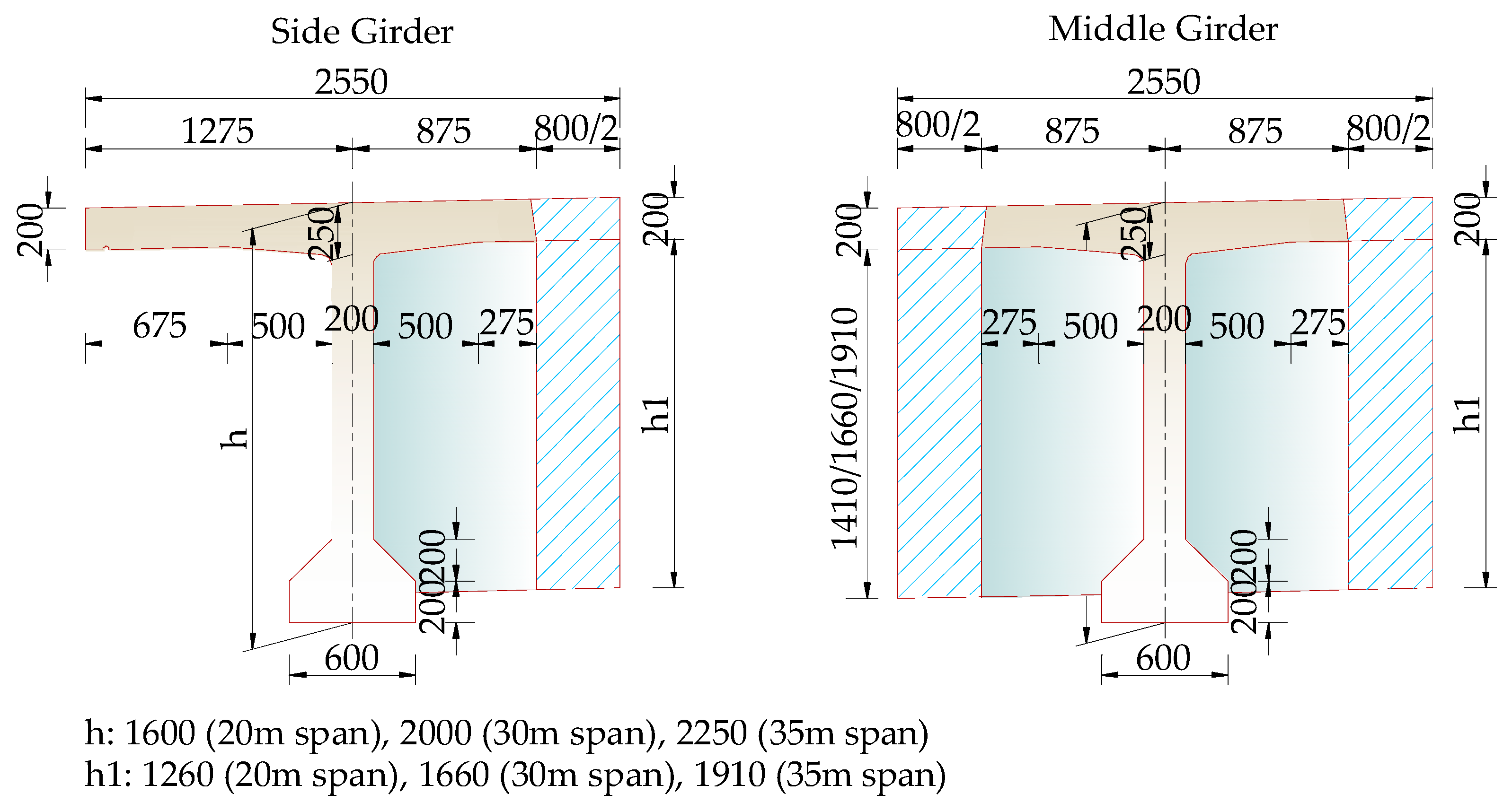
The bridge spans were 6 × 30 m, and the deck accommodated two-way traffic with eight lanes and featured T-shaped girders and cylindrical piers. The upper structures of the new bridge and the old bridge were connected by rigid splicing of the flanges and the transverse diaphragms. There were no connections with the lower structures, as shown in Figure 11. A vertical view of the whole bridge is shown in Figure 12.
The finite element model of the bridge was built with Midas/Civil 2021 software, the longitudinal elements of which were simulated according to the related girder sections and the virtual crossbeam simulated by the actual widths of the wet joints and the transverse diaphragms. The dimensions of the T-shaped girder section are shown in Figure 13.
The upper structures of the bridge used C50 concrete. The splicing utilized either the concrete material selected in Section 3.2 or C50 concrete. The piers were constructed with C40 concrete. The girders employed HPB300 reinforcement (for diameters less than 10 mm) and HRB400 reinforcement (for diameters greater than 10 mm), with a standard strength of f pk = 1860   MPa . The detailed parameters of the materials are listed in Table 3.
Beam elements were selected for the simulation of the girders and piers in Midas/Civil 2021 software. In order to accelerate the calculation, the cap beams of the piers were replaced by the elastic connections between the girders and the piers according to the support types, and the bottoms of the piers were considered as rigid joints. The support conditions were arranged as in Figure 14.
The heights of the piers were unified to 10 m based on previous experience, the guardrail loads were equivalent to 12.5 kN/m at both sides of the bridge deck, and the traffic loads were combined by the lane loads and vehicle loads, referencing to the regulations on the most unfavorable loading method in the specification JTG D60-2015 [23]. The uneven foundation settlement of the new bridge was simulated by a 2 mm vertical displacement at the bottom of the piers. The finite element model of the bridge is shown in Figure 15.
The design schemes for the splicing structures are listed in Table 4.
The changes in the transverse distribution coefficients of each girder of the old bridge in the different splicing schemes are shown in Figure 16.
From the results above, with the increase in the number of splicing transverse diaphragms, the vehicle load effects on the old bridge were further weakened. However, when the number of splicing transverse diaphragms exceeded two, there was no significant further reduction in the vehicle load effects, and the reduction for the #6 girder remained around 58%. Additionally, changing the type of splicing materials can improve the stress performance of the splicing structures to some extent.
Under the effects of the uneven foundation settlement of the new bridge, the force variations of the #6 girder (splicing girder) in the different schemes are shown in Figure 17.
After the splicing, the maximum positive bending moment of the #6 girder has been reduced, while no severe variation occurred in the negative bending moment, revealing that the splicing of the transverse diaphragms could improve the stress of the splicing seams to a certain extent. The increase in quantity of the transverse diaphragms could enhance the transverse stiffness of the old bridge, leading to an increase inf the positive bending moment at the transverse diaphragm and a decrease at the middle span, which would be beneficial for the stress of the middle span.
In summary, changing the type of splicing materials and installing transverse diaphragms can effectively improve the stress conditions of the old bridge girders and splicing seams. However, when the number of splicing transverse diaphragms exceeds two, the improvement becomes less significant, which is consistent with the results of the iteration algorithm. Compared with the early methods for the optimization design of the splicing structures [28,29,30,31], the method proposed in this paper was suitable for the splicing structure designs of the beam bridges with T-shaped girders.

3.3.2. Verification of the Effectiveness with the Measured Data

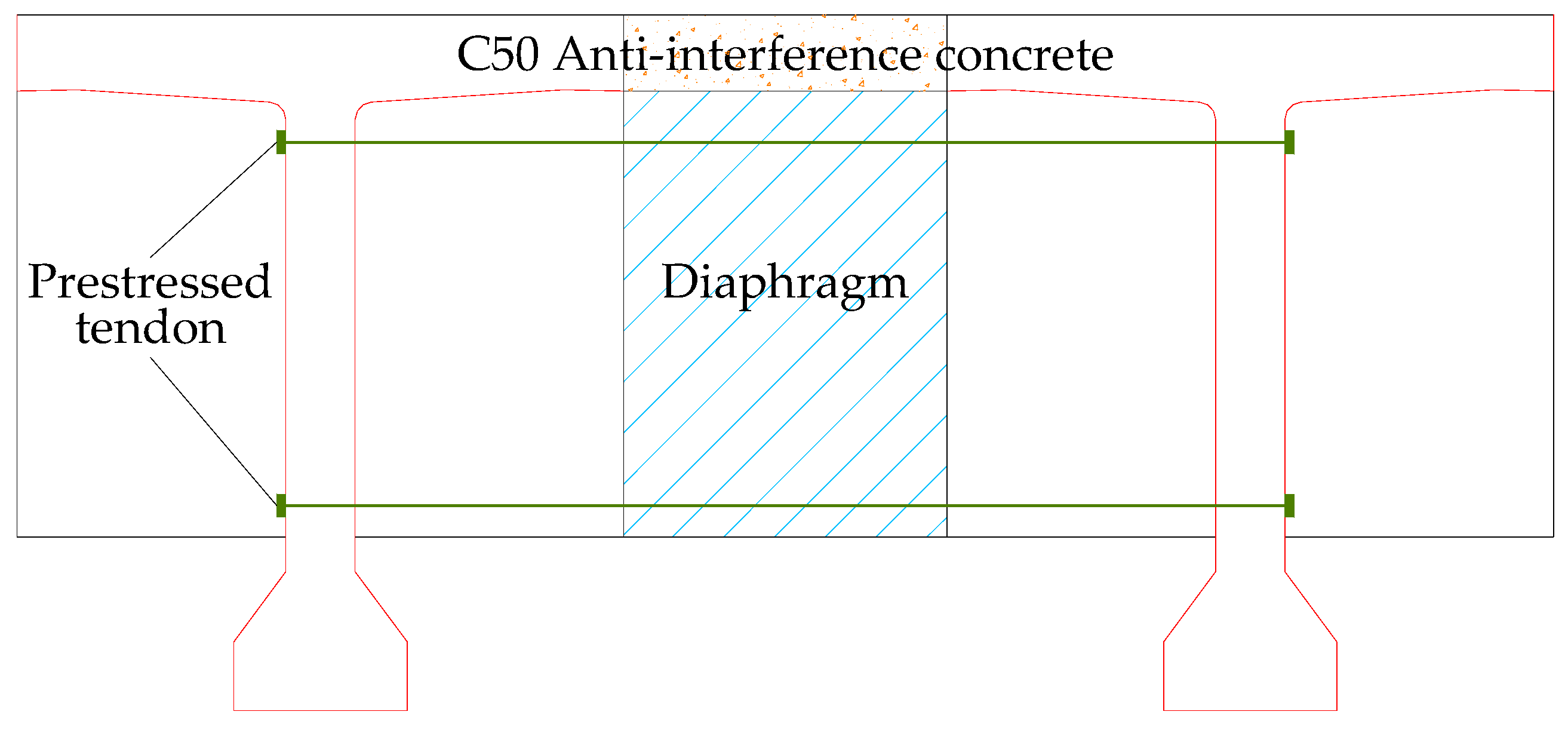
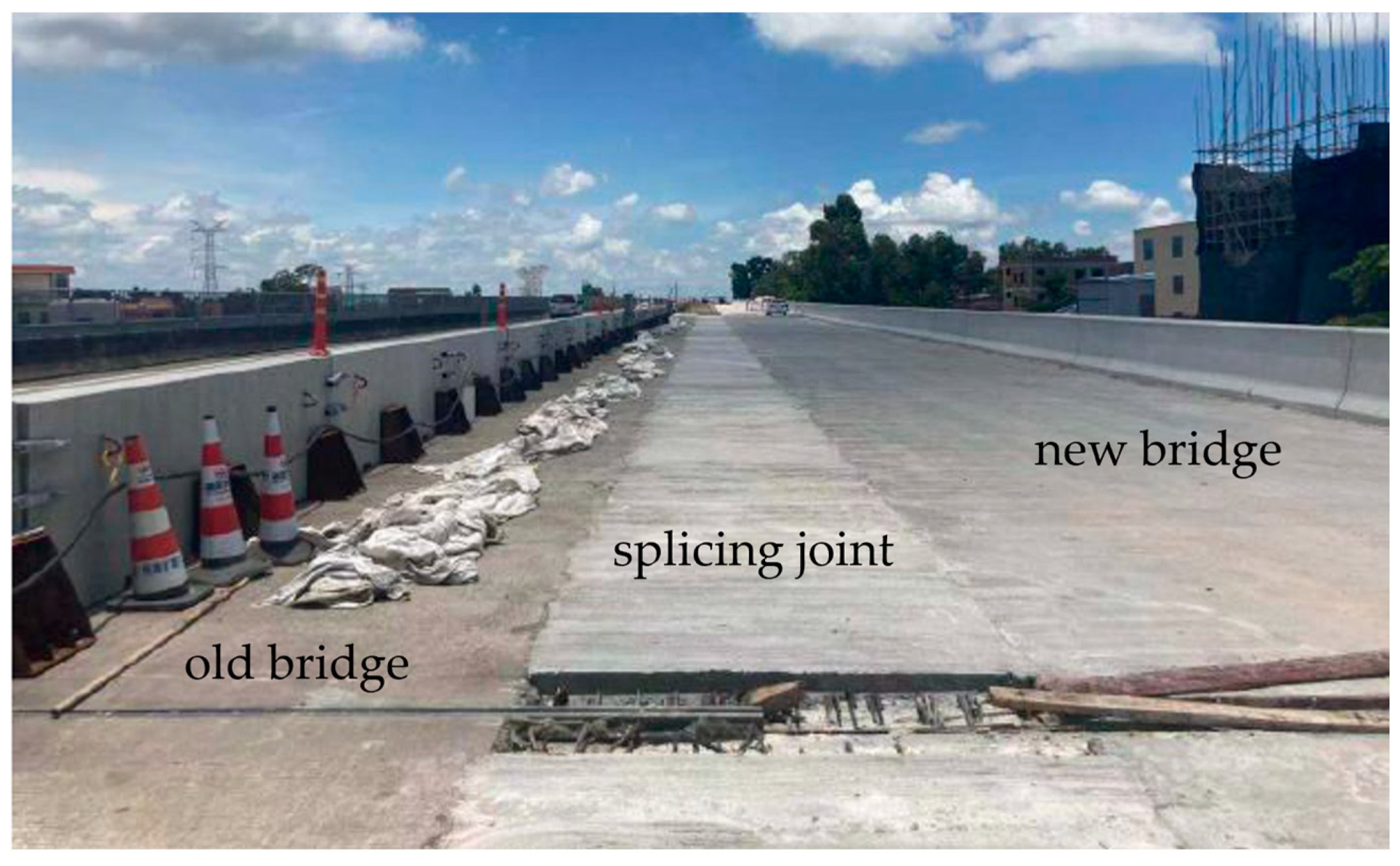
According to the calculation results of this method, the new and old bridges were spliced together. The splicing structures are shown in Figure 18, and the realistic effects after splicing are shown in Figure 19.
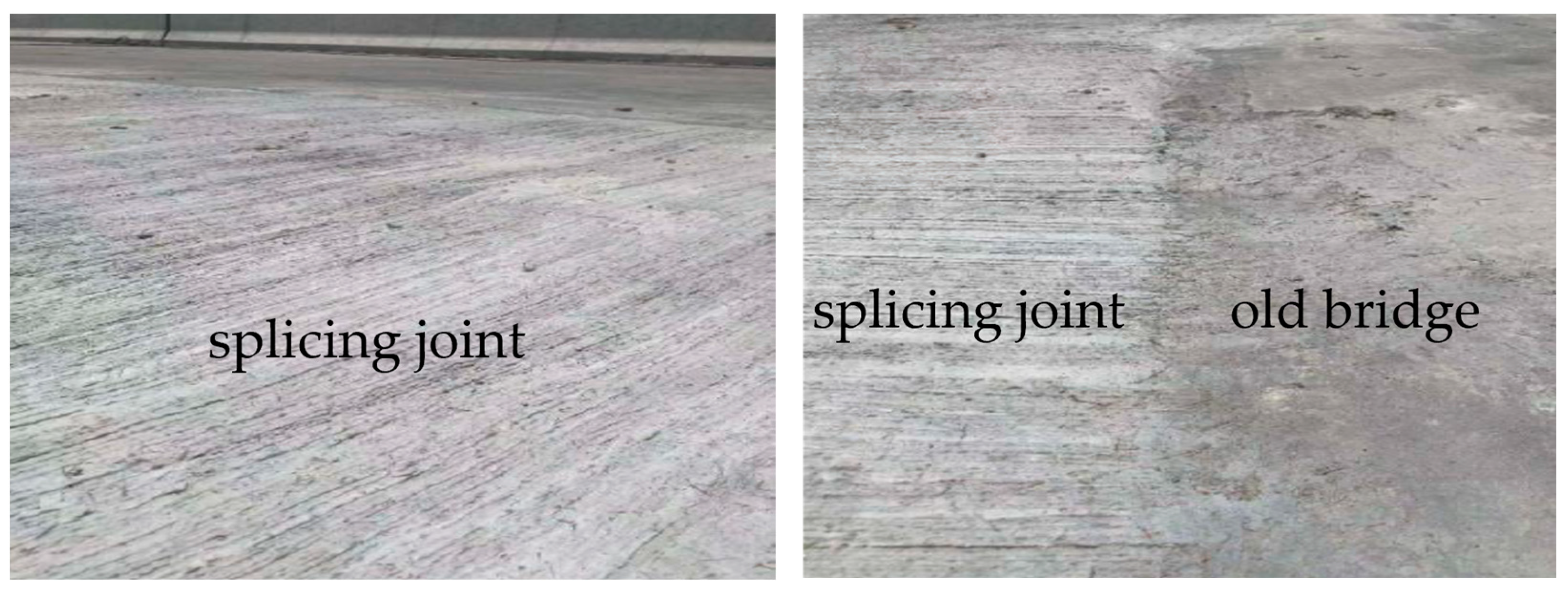
The foundation settlements of the new bridge after the splicing were 1 mm, and the crack situation of the bridge deck is shown in Figure 20.
Observation points were arranged at each pier once the concrete molding was finished, and the daily measurement was cast by the Electronic Total Station until the bridges were open for traffic operation. The maximum cumulative settlement of each pier was selected as the maximum total settlement. The maximum total settlement of the new bridge was smaller than the assumption design value of 2 mm, and no observable cracks were found in the bridge deck, verifying the effectiveness of the method in this paper.

4. Conclusions

Addressing the difficulties in relation to bridge-splicing technology, a multi-technique hybrid method for the widening and splicing of new and old beam bridges was proposed in this paper, angling the splicing materials, the reinforcement ratio of the splicing structure, and the quantity selection of the transverse diaphragms. Some conclusions can be summarized as follow:
(1)
The results of no observable cracks in the splicing structures after the splicing construction could testify to the effectiveness of the selection method for the materials based on the maximum stress at the splicing interface.
(2)
The maximum total settlements of the new bridges after the splicing construction were under 1 mm (smaller than the assumption design value of 2 mm), which has indicated that the minimum longitudinal reinforcement ratio of the splicing structures could be accurately calculated by the method based on the allowable stress value of the splicing materials in this paper.
(3)
Increasing the number of splicing transverse diaphragms can improve the structural stress conditions to some extent, but when the number reaches a certain limit, the improvement effect will significantly decrease.
(4)
The methods mentioned in this paper could be applicable to all widening and splicing projects with T-shaped girders for new and old bridges.

Author Contributions

Methodology, Z.T.; validation, J.Y.; writing—original draft preparation, Z.T., J.Y. and S.Z.; writing—review and editing, Z.T. and S.Z. All authors have read and agreed to the published version of the manuscript.

Funding

This research was supported by the Science and Technology Project of the Department of Transportation of Heilongjiang Province (HJK2023B020).

Institutional Review Board Statement

Not applicable.

Informed Consent Statement

Not applicable.

Data Availability Statement

The data presented in this study are available on request from the corresponding author.

Conflicts of Interest

Author Zhicheng Tan was employed by Hunan Provincial Communications Planning, Survey & Design Institute Co., Ltd. and author Jiangchuan Yu was employed by Qilu Traffic Qingdao Investment Development Limited Company. The remaining author declares that the research was conducted in the absence of any commercial or financial relationships that could be construed as a potential conflict of interest.

References

  1. Kong, Q.M.; Lv, H.J. Study on the Splicing Method between New and Old Bridges. Appl. Mech. Mater. 2012, 204–208, 2257–2260. [Google Scholar] [CrossRef]
  2. Hosseini, M.; Jefferson, A.D. Time-dependent behaviour of widened reinforced concrete under-bridge. Mater. Struct. 1998, 31, 714–719. [Google Scholar] [CrossRef]
  3. Shi, X.; Li, X.; Ruan, X.; Ying, T. Analysis of Structural Behaviour in Widened Concrete Box Girder Bridges. Struct. Eng. Int. 2008, 18, 351–355. [Google Scholar] [CrossRef]
  4. Zhou, Z.; Ma, X.; Liu, Y.; Li, H. A method for monitoring the uneven settlement of shield tunnels considering the flattening effect using distributed strain data measured from BOTDA sensors. Struct. Health Monit. 2024. [Google Scholar] [CrossRef]
  5. Wen, Q.-J. Long-term effect analysis of prestressed concrete box-girder bridge widening. Constr. Build. Mater. 2011, 25, 1580–1586. [Google Scholar] [CrossRef]
  6. Tu, B.; Fang, Z.; Dong, Y.; Frangopol, D.M. Time-variant reliability analysis of widened deteriorating prestressed concrete bridges considering shrinkage and creep. Eng. Struct. 2017, 153, 1–16. [Google Scholar] [CrossRef]
  7. Wen, Q.-J.; Jing, H.-W. Numerical simulation of creep and shrinkage in widened concrete bridges. Mag. Concr. Res. 2014, 66, 661–673. [Google Scholar] [CrossRef]
  8. Sun, Q.; Liu, C.; Sha, L.; Lu, Y. Experimental study on bending performance of different types of UHPC in bridge stitching joint. Mater. Struct. 2021, 54, 179. [Google Scholar] [CrossRef]
  9. Liu, Y.; Gao, M. Detecting cracks in concrete structures with the baseline model of the visual characteristics of images. Comput. -Aided Civ. Infrastruct. Eng. 2022, 37, 1891–1913. [Google Scholar] [CrossRef]
  10. Gui, S.; Liu, L.; Chen, S.; Zhao, H. Research on Models of a Highway Bridge Subjected to a Moving Vehicle Based on the LS-DYNA Simulator. J. Highw. Transp. Res. Dev. (Engl. Ed.) 2014, 8, 76–82. [Google Scholar] [CrossRef]
  11. Guo, J.; Deng, K.; He, M.; Zhao, C.; Li, W. Experimental Study on the Construction Stages of an RC Closure Pour in Bridge Widening. J. Bridge Eng. 2017, 22, 06017007. [Google Scholar] [CrossRef]
  12. Dunham, M.R.; Rush, A.S.; Hanson, J.H. Effects of Induced Vibrations on Early Age Concrete. J. Perform. Constr. Facil. 2007, 21, 179–184. [Google Scholar] [CrossRef]
  13. Zhang, L.; Yan, J.; Ma, H.; Yu, H.; Wang, Y.; Mei, Q. Experimental Study on Magnesium Sulfate Cement Concrete Splices of Widened Box Girder. KSCE J. Civ. Eng. 2021, 25, 4742–4750. [Google Scholar] [CrossRef]
  14. Chai, Y.H.; Hung, H.J. Waiting Period for Closure Pours in Bridge Widening or Staged Construction. J. Bridge Eng. 2016, 21, 04016006. [Google Scholar] [CrossRef]
  15. Kwan, A.K.H.; Ng, P.L. Reducing damage to concrete stitches in bridge decks. Proc. Inst. Civ. Eng. Bridge Eng. 2006, 159, 53–62. [Google Scholar] [CrossRef]
  16. Chen, D.; Zhu, C.; Shi, X.; Song, J. Influence of Random Vehicle–Bridge Coupling Vibration on the Anti-Disturbance Performance of Concrete Materials. Appl. Sci. 2023, 13, 7584. [Google Scholar] [CrossRef]
  17. Zhang, W.; Zheng, D.; Huang, Y.; Kang, S. Experimental and simulative analysis of flexural performance in UHPC-RC hybrid beams. Constr. Build. Mater. 2024, 436, 136889. [Google Scholar] [CrossRef]
  18. Huang, H.; Xue, C.; Zhang, W.; Guo, M. Torsion design of CFRP-CFST columns using a data-driven optimization approach. Eng. Struct. 2022, 251, 113479. [Google Scholar] [CrossRef]
  19. Wu, W.; Zhang, H.; Liu, Z.; Wang, Y. Numerical Analysis on Transverse Splicing Structure for the Widening of a Long Multi-Span Highway Concrete Continuous Box Girder Bridge. Materials 2022, 15, 6805. [Google Scholar] [CrossRef]
  20. Nguyen, H.; Carvelli, V.; Adesanya, E.; Kinnunen, P.; Illikainen, M. High performance cementitious composite from alkali-activated ladle slag reinforced with polypropylene fibers. Cem. Concr. Compos. 2018, 90, 150–160. [Google Scholar] [CrossRef]
  21. Wang, W.; Liu, S.; Wang, Q.; Yuan, W.; Chen, M.; Hao, X.; Ma, S.; Liang, X. The Impact of Traffic-Induced Bridge Vibration on Rapid Repairing High-Performance Concrete for Bridge Deck Pavement Repairs. Adv. Mater. Sci. Eng. 2014, 2014, 632051. [Google Scholar] [CrossRef]
  22. Zhang, X.; Liu, S.; Yan, C.; Wang, X.; Wang, H. Effects of Vehicle-Induced Vibrations on the Tensile Performance of Early-Age PVA-ECC. Materials 2019, 12, 2652. [Google Scholar] [CrossRef]
  23. JTG D60-2015; General Code for Design of Highway Bridges and Culverts. Chinese Standard: Beijing, China, 2015.
  24. GB/T50010-2010; Code for Design of Concrete Structures. Chinese Standard: Beijing, China, 2010.
  25. JTG 5120-2021; Highway Bridge and Culvert Maintenance Code. Chinese Standard: Beijing, China, 2021.
  26. JTG/TH21-2011; Standards for Technical Condition Evaluation of Highway Bridges. Chinese Standard: Beijing, China, 2011.
  27. JTG/T J22-2008; Specifications for Strengthening Design of Highway Bridges. Chinese Standard: Beijing, China, 2008.
  28. Huang, H.; Yao, Y.; Liang, C.; Ye, Y. Experimental study on cyclic performance of steel-hollow core partially encased composite spliced frame beam. Soil Dyn. Earthq. Eng. 2022, 163, 107499. [Google Scholar] [CrossRef]
  29. Yao, Y.; Huang, H.; Zhang, W.; Ye, Y.; Xin, L.; Liu, Y. Seismic performance of steel-PEC spliced frame beam. J. Constr. Steel Res. 2022, 197, 107456. [Google Scholar] [CrossRef]
  30. Choi, H.K.; Choi, Y.C.; Choi, C.S. Development and testing of precast concrete beam-to-column connections. Eng. Struct. 2013, 56, 1820–1835. [Google Scholar] [CrossRef]
  31. Du, H.; Hu, X.; Shi, D.; Fang, B. Effect of reinforcement on the strength of the web opening in steel-concrete composite beam. Eng. Struct. 2021, 235, 112038. [Google Scholar] [CrossRef]
Figure 1. Diagram of the cross-section of bridge splicing.
Sustainability 16 06164 g001
Figure 2. A method for the widening and splicing of new and old beam bridges combined with multiple technologies.
Sustainability 16 06164 g002
Figure 3. Diagram of bridge splicing.
Sustainability 16 06164 g003
Figure 4. Conversion diagram of the actual structures and the equivalent analogic orthotropic plates. (a) Diagram of the actual structures. (b) Diagram of the equivalent analogic orthotropic plates.
Sustainability 16 06164 g004
Figure 5. Iteration algorithm for calculating the minimum quantity of the transverse diaphragms.
Sustainability 16 06164 g005
Figure 6. Calculation process of the method for the widening and splicing of new and old beam bridges combined with multiple technologies.
Sustainability 16 06164 g006
Figure 7. Photos of the selected bridges.
Sustainability 16 06164 g007
Figure 8. Diagrams of the vertical and cross-section views of the selected bridge.
Sustainability 16 06164 g008
Figure 9. Flange concrete of the old bridge stripped by high-pressure water.
Sustainability 16 06164 g009
Figure 10. Reinforcement planting.
Sustainability 16 06164 g010
Figure 11. Cross-section view of the actual bridge.
Sustainability 16 06164 g011
Figure 12. Vertical view of the actual bridge.
Sustainability 16 06164 g012
Figure 13. Diagrams of the cross-sections of the T-shaped girder.
Sustainability 16 06164 g013
Figure 14. Support layout diagram.
Sustainability 16 06164 g014
Figure 15. Finite element model of the bridge.
Sustainability 16 06164 g015
Figure 16. Changes in the transverse distribution coefficients of the old bridge. (a) Transverse distribution coefficients of the old bridge. (b) Reduction rate of the transverse distribution coefficients of the old bridge.
Sustainability 16 06164 g016
Figure 17. Bending moment diagram of the #6 girder in the different schemes. (a) Bending moment diagram of the #6 girder in Scheme 1 (unit: kN·m). (b) Bending moment diagram of the #6 girder in Scheme 2 (unit: kN·m). (c) Bending moment diagram of the #6 girder in Scheme 3 (unit: kN·m). (d) Bending moment diagram of the #6 girder in Scheme 4 (unit: kN·m).
Sustainability 16 06164 g017
Figure 18. Diagram of the splicing of the transverse diaphragms.
Sustainability 16 06164 g018
Figure 19. Realistic effects after splicing of the new and old bridges.
Sustainability 16 06164 g019
Figure 20. Crack situation of the bridge deck after widening and splicing.
Sustainability 16 06164 g020
Table 1. Minimum reinforcement ratio of the longitudinal section of the splicing structures.
Width of the Splicing Seam (cm)Minimum Reinforcement Ratio of the Splicing Girders on the Old Bridges (%)ρy,min (%)
451.421.21
751.441.59
Table 2. Scheme for the reinforcement planting.
PositionSchemeReinforcement RatioComprehensive Reinforcement Ratio
Beam end~1/4 spanΦ12@45cm0.33%0.42%
1/4 span~3/4 spanΦ12@30cm0.50%
Table 3. Material parameters of the finite element model.
MaterialDensity (kg/m3)Elastic Modulus (MPa)Poisson’s Ratio
C40 concrete243033,0000.22
FRADC238032,0000.22
C50 concrete250034,5000.20
HPB300 reinforcement7850206,0000.30
HRB400 reinforcement7850207,0000.30
Table 4. Splicing schemes for the new and old bridges.
No.Splicing MaterialsTransverse Diaphragm Number
1FRADC1
2C502
3FRADC2
4FRADC3
Disclaimer/Publisher’s Note: The statements, opinions and data contained in all publications are solely those of the individual author(s) and contributor(s) and not of MDPI and/or the editor(s). MDPI and/or the editor(s) disclaim responsibility for any injury to people or property resulting from any ideas, methods, instructions or products referred to in the content.