
Energy and Environmental Analyses of a Solar–Gas Turbine Combined Cycle with Inlet Air Cooling

 ,
,  , and
, and 
Abstract
1. Introduction
1.1. The First Problem of GTs: Waste Heat
1.2. The Second Problem of GTs: Excessive Amount of Fuel
1.3. The Third Problem of GTs: Sensitivity to Ambient Air Temperature
1.3.1. Ambient Air Temperature Control by Inlet-Air-Cooling Techniques
1.3.2. The Effect of Inlet Air Cooling on Fuel Consumption
1.4. Problem Statement and Motivation for This Study
- An actual GTCC was integrated with a PTC. Hence, the initial GT dilemma was resolved using a steam generator with a heat recovery system to operate an ST to generate extra power.
- A new CSS was introduced with two SHEs powered by PTCs to address the second and third dilemmas.
- ○
- The first solar heat exchanger, SHE1, was utilized to preheat the air that enters the combustion chamber to decrease the amount of fuel the system uses, hence further decarbonizing the system.
- ○
- The second solar heat exchanger, SHE2, operated an ACU to decrease the compressor’s inlet air temperature to 5 °C. According to the recommendation, the air temperature cooling was limited to this temperature to attain the highest output power while eliminating the possibility of ice formation on the compressor’s blades.
- A solution that simultaneously addresses the three problems of GTCC plants using solar energy is presented.
- The energy of the integration is explored by employing thermodynamic, heat transfer equations, and semi-empirical equations.
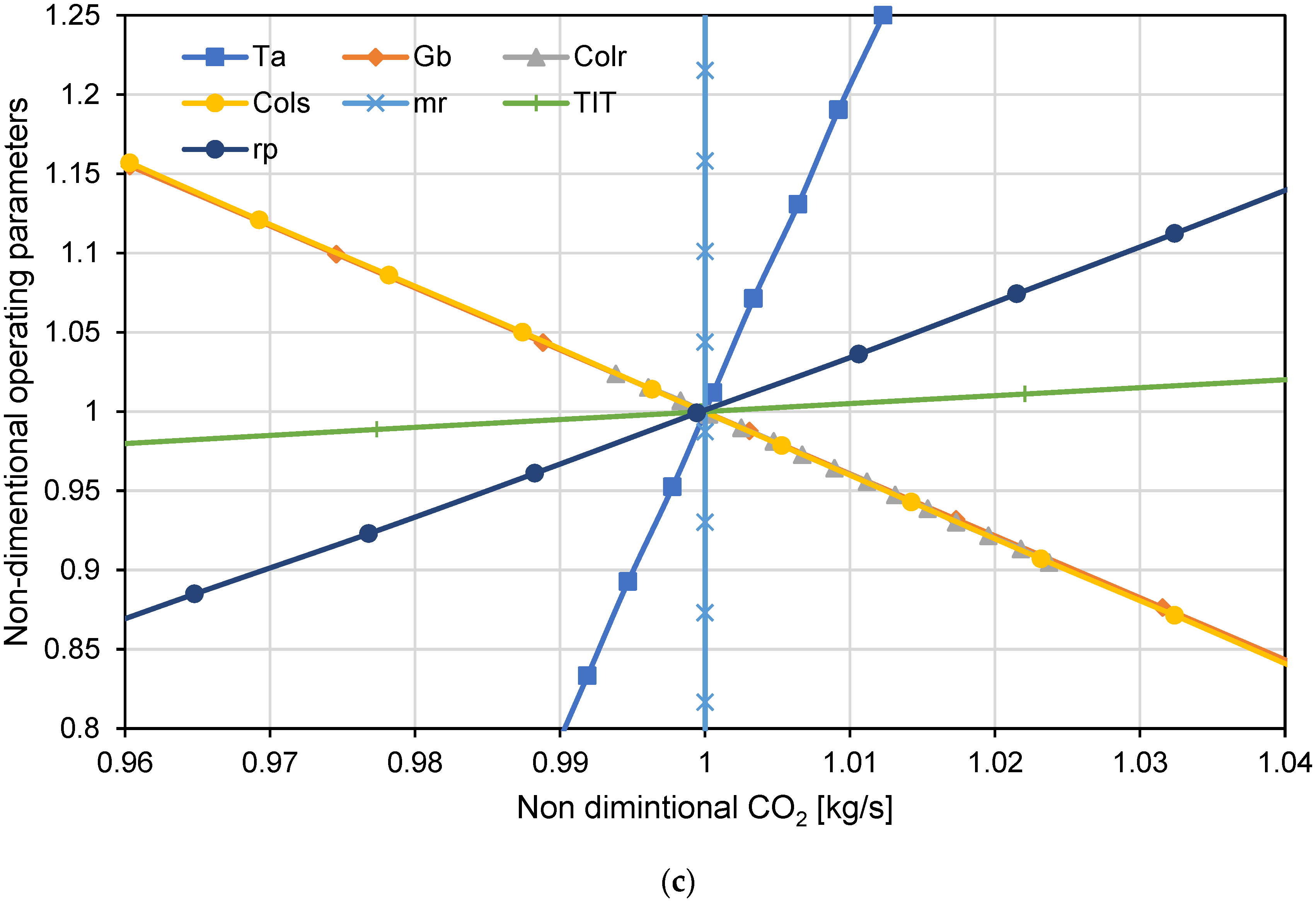
- The environmental aspects of the combined cycle are improved by reducing greenhouse gas emissions and pollutants (CO, CO2, and NOx).
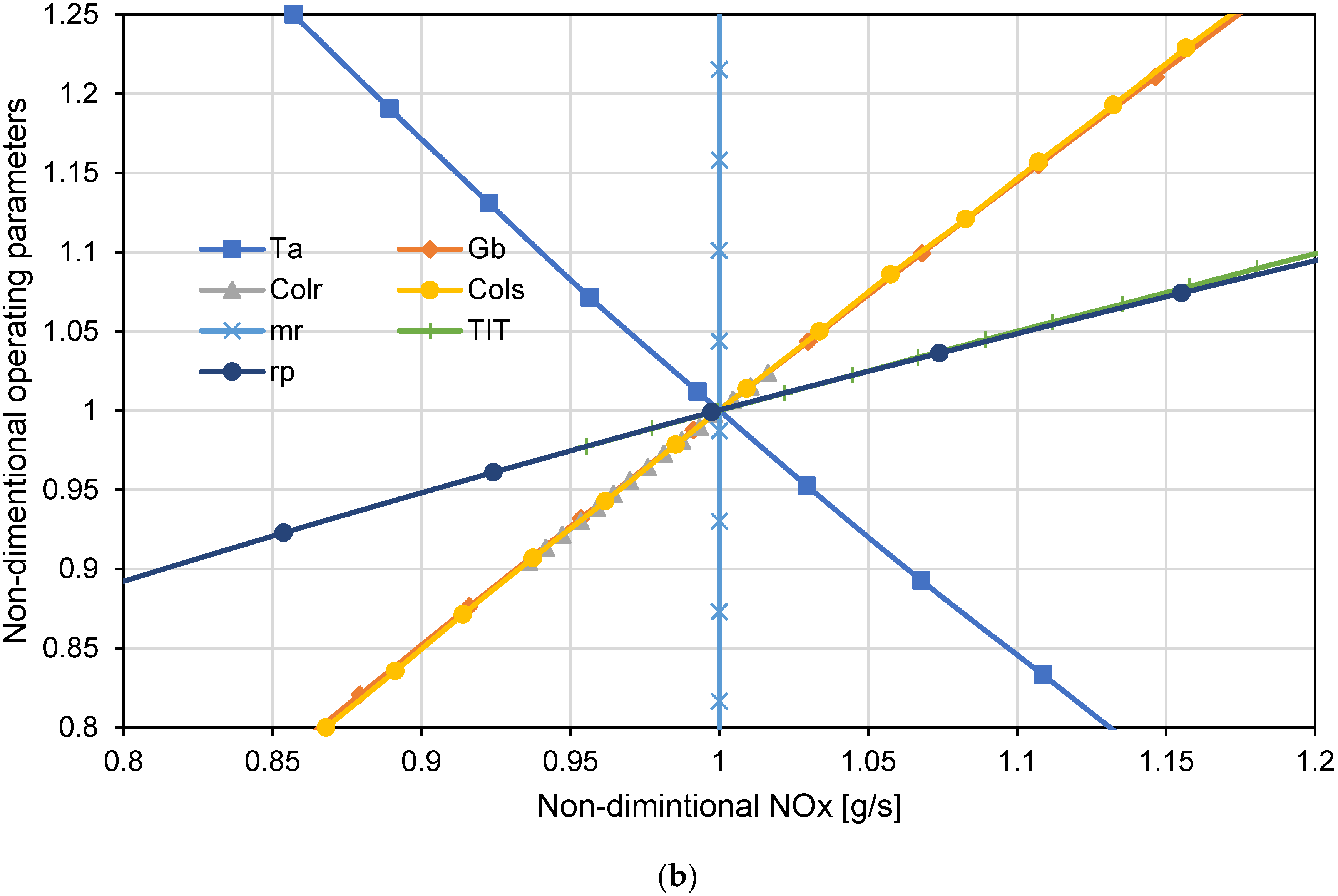
- A parametric spider diagram study of the major operating parameters is used to examine their impact on the power plant’s performance and pollutant emissions.
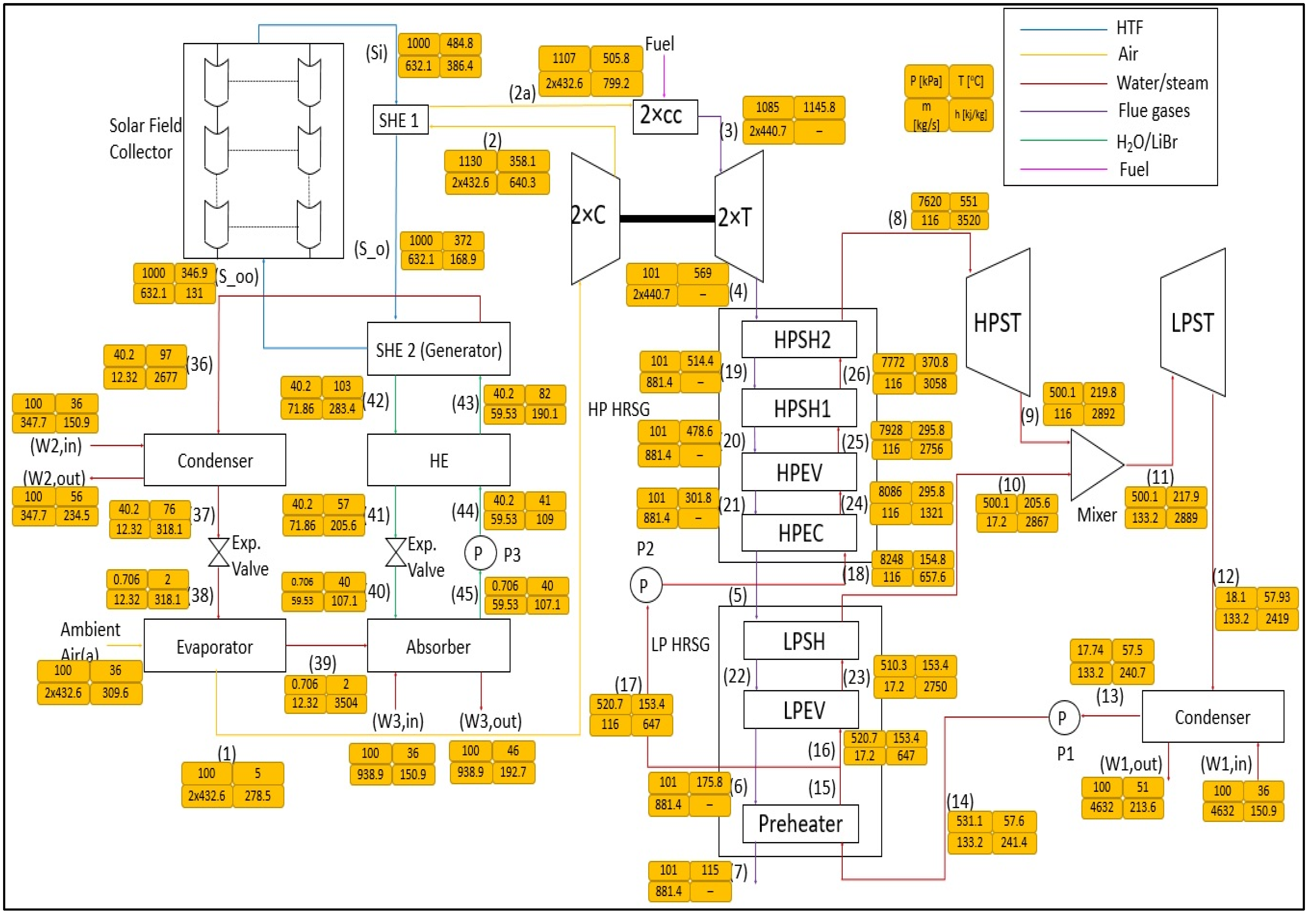
2. System Description
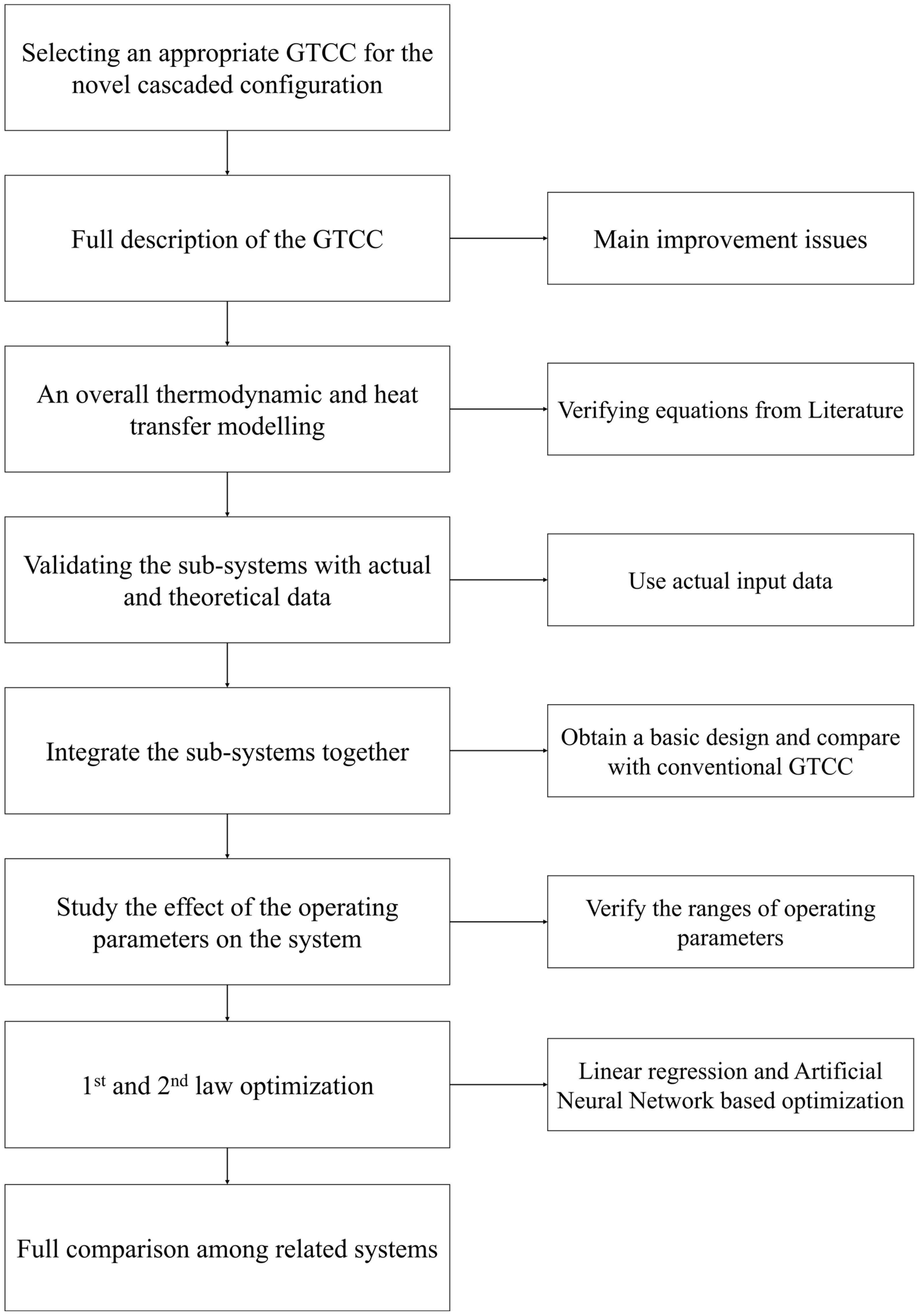
3. Power Plant Modeling
- All PACC components are adiabatic.
- Steady-state conditions are achieved.
- Negligible kinetic and potential energies are achieved [37], since the cooling load that is required by the ACU and the heat input required for the compressed air are acquired from the GTs.
- A pressure drop was assumed to occur through each heat exchanger unit [24].
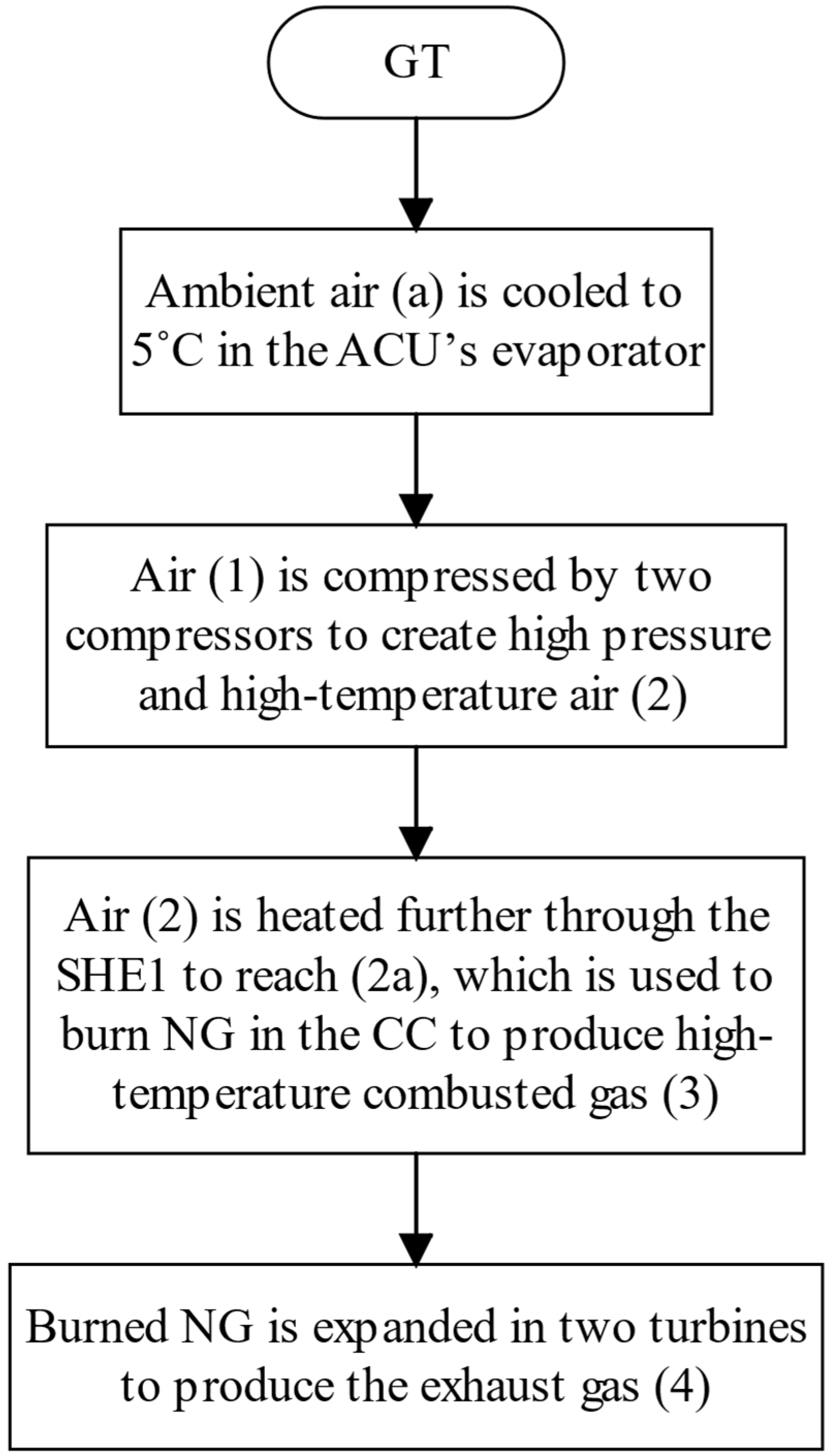
3.1. Modeling of GT Unit
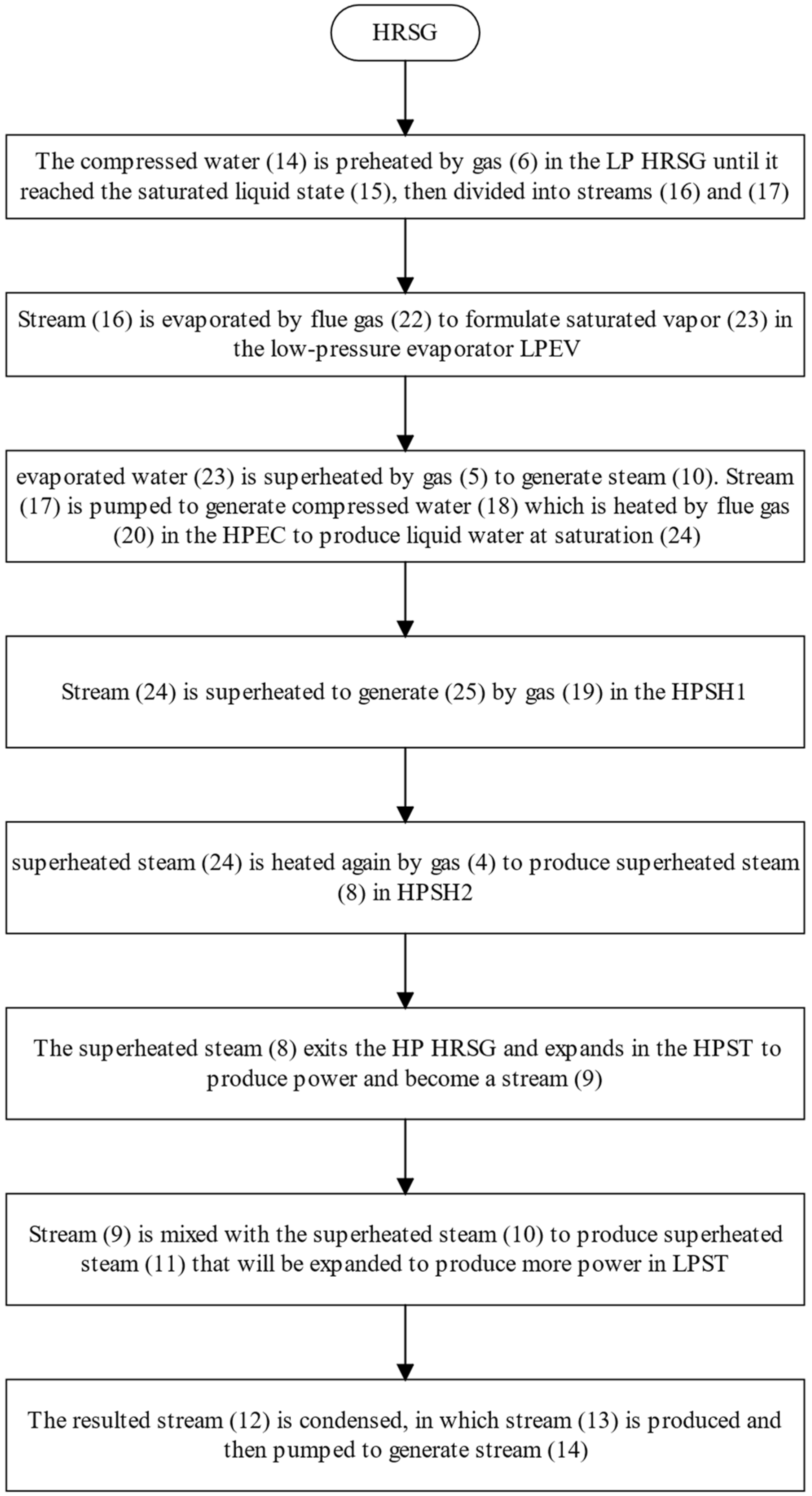
3.2. Modeling of the HRSG Unit
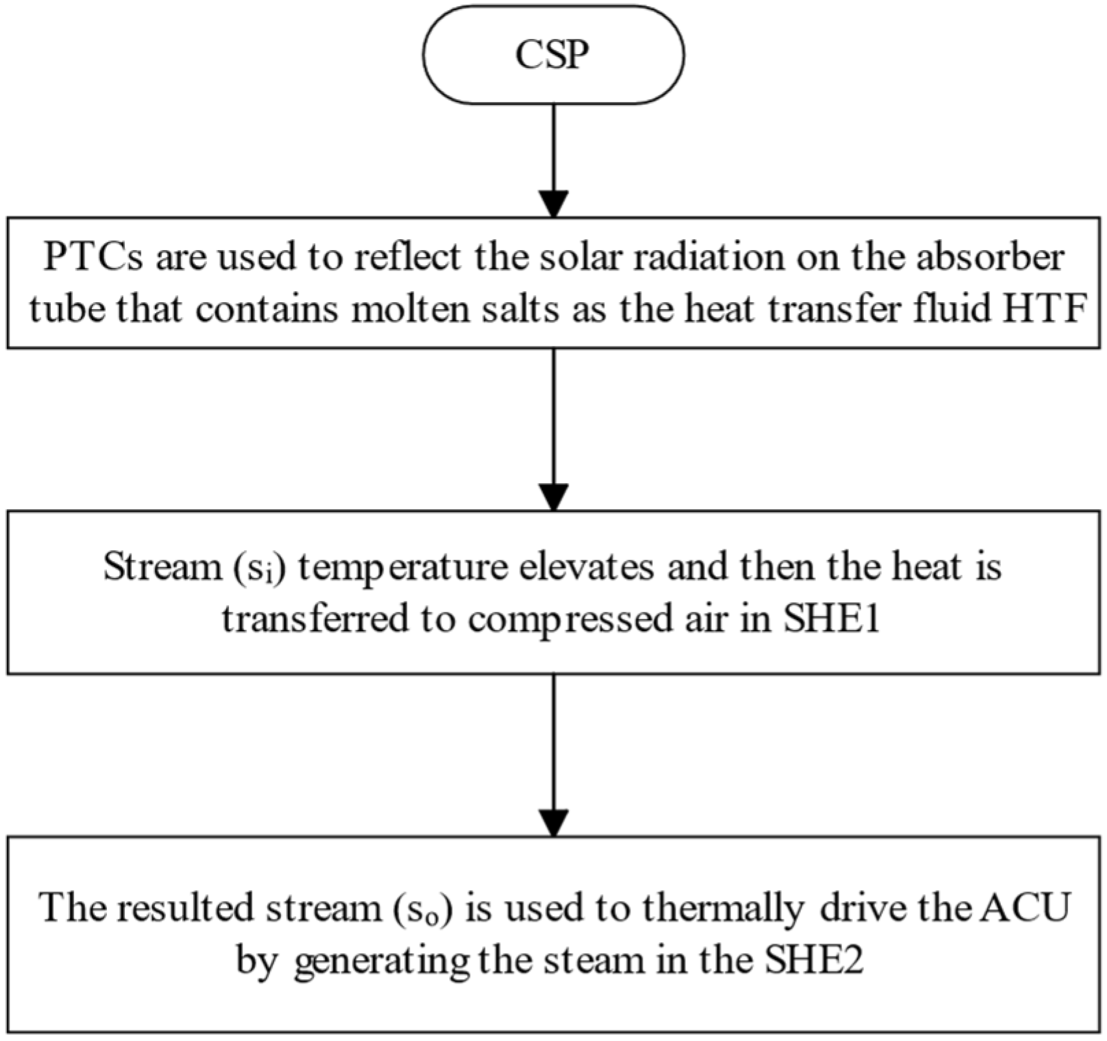
3.3. Modeling of the CSP Unit
3.4. Modeling of ACU
3.5. Thermo-Environomic Modeling
3.6. Overall Performance Analysis
4. Results and Discussion
4.1. Validation of the Developed Model
4.2. Design Point Calculations
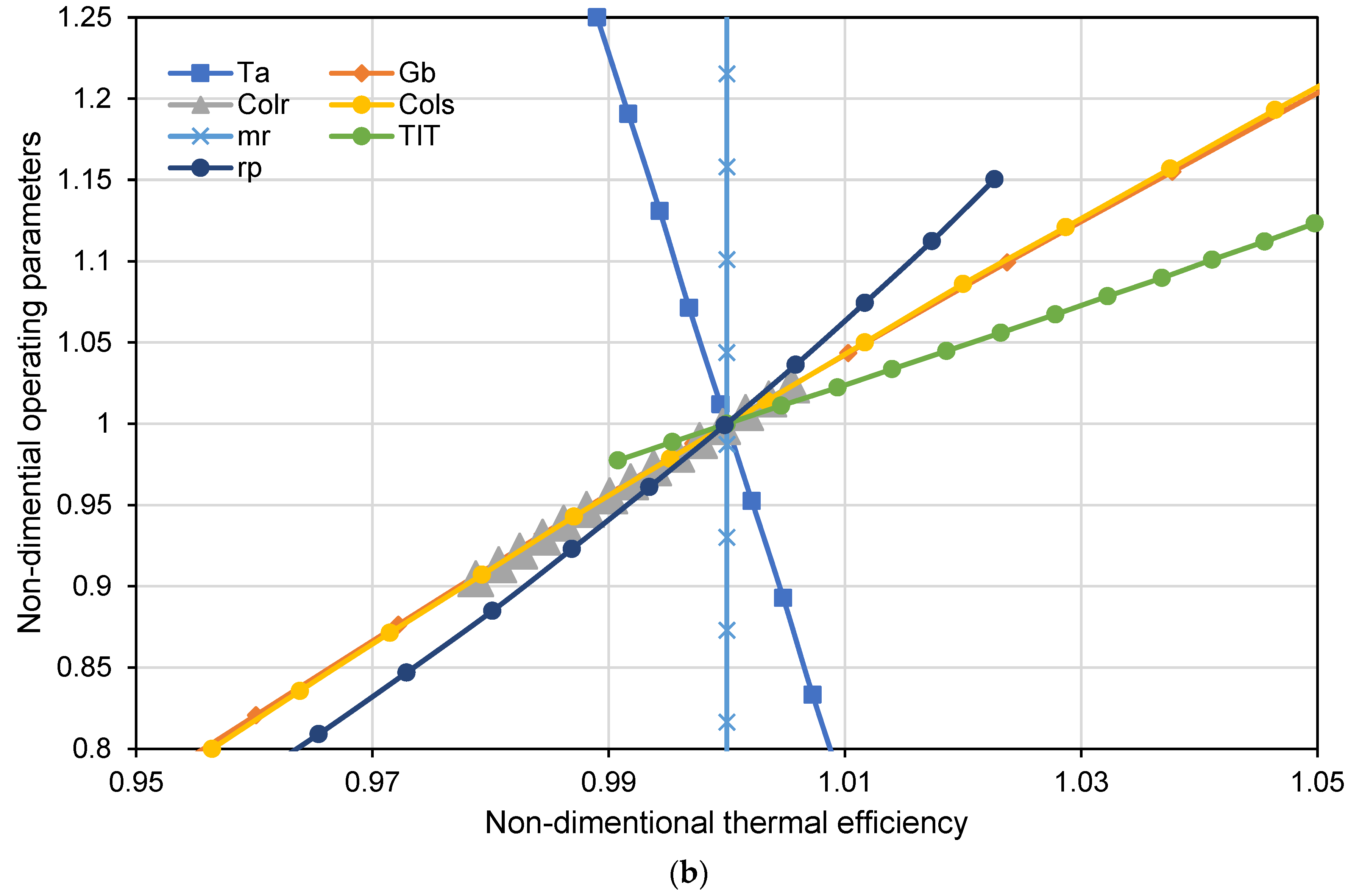
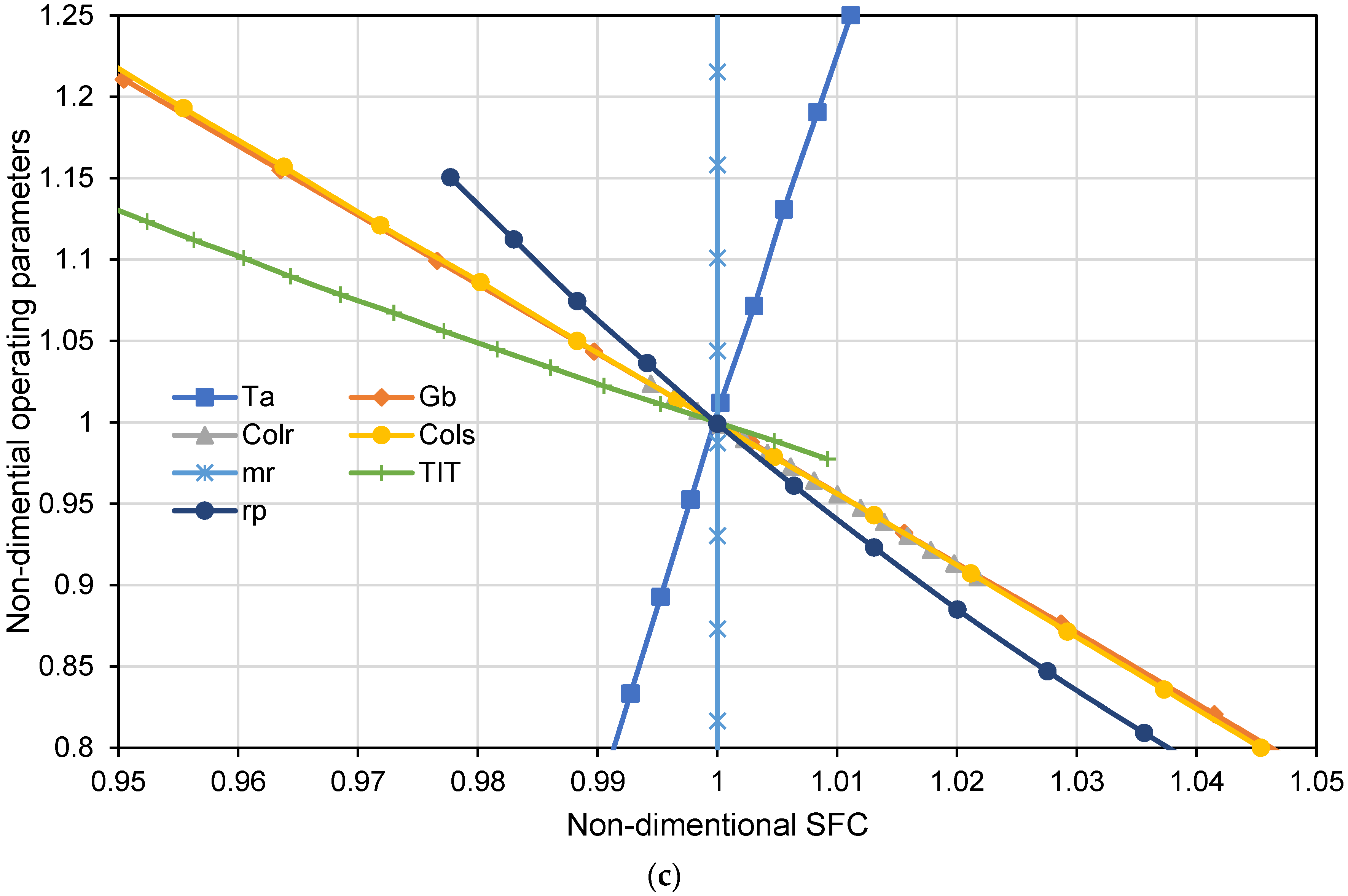
4.3. Variation Impact of the Operating Parameters on the Performance of the System
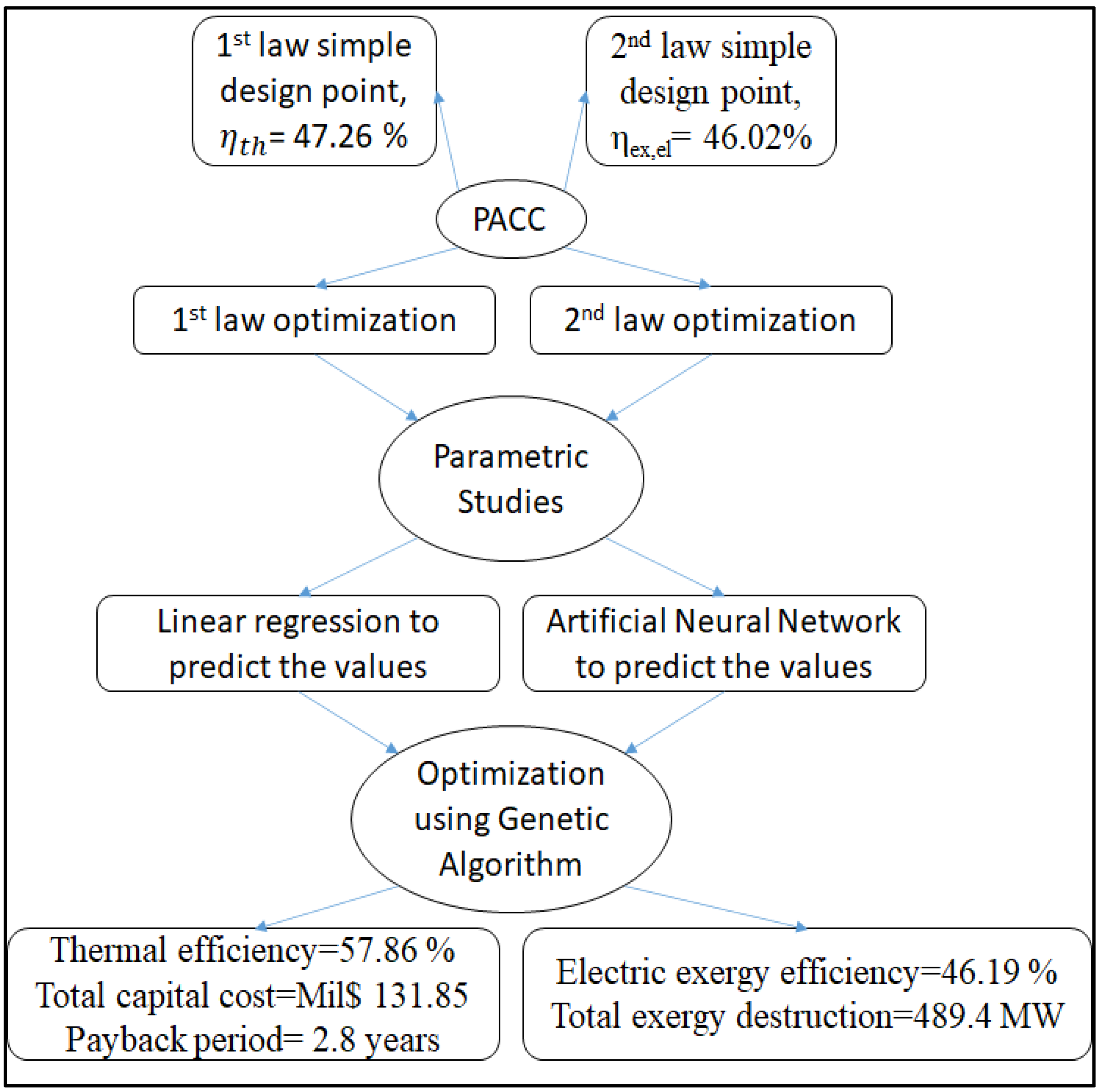
4.4. The First and Second Laws of Thermodynamics Optimization
4.5. Evaluation of the Proposed System’s Improvements
5. Conclusions
- (1)
- The method proposed in this study assesses the overall performance of the gas turbine system, which can be applied to evaluate other existing and future GT powerplants.
- (2)
- A cascaded solar power system was proposed to improve the system’s overall performance, increase the power generation at the design point by 6.87%, and improve thermal efficiency by 19.5% with a 10.53% reduction in fuel consumption.
- (3)
- The ACU successfully lowered the ambient temperature to 5 °C using the available solar power that drives the generator (solar heat exchanger number 2), resulting in the compressors’ lowest consumed power.
- (4)
- Utilizing solar power in solar heat exchanger number 1 saved the maximum amount of NG fuel input by solving two problems: the conventionally high amounts of fuel required for generating power in the GTs and the rise in the temperature difference caused by the inlet air cooling.
- (5)
- The effect of each of the seven main operating parameters on the overall performance of the system was quantified and explained.
Author Contributions
Funding
Institutional Review Board Statement
Informed Consent Statement
Data Availability Statement
Acknowledgments
Conflicts of Interest
Abbreviations
| ACU | Absorption chilling unit |
| CC | Combustion chamber |
| CCGT | Combined-cycle gas turbine |
| Colr | Number of collectors in row |
| Cols | Number of collectors in series |
| CSP | Concentrated solar power |
| CSS | Cascade solar system |
| CWHR | Cascaded waste heat recovery |
| EES | Engineering equation solver |
| Gb | Solar irradiation |
| GTs | Gas turbines |
| GTCC | Gas turbine-combined cycle |
| GTPPs | Gas turbine power plants |
| HP | High-pressure heat recovery steam generator |
| HPEC | High-pressure economizer |
| HPSH | High-pressure superheater |
| HPST | High-pressure steam turbine |
| HRSG | Heat recovery steam generation |
| HRU | Heat recovery unit |
| HTF | Heat transfer fluid |
| IAC | Inlet air cooling |
| ISCCs | Integrated solar combined cycle power plants |
| LFCs | Linear Fresnel collectors |
| LHV | Lower heating value |
| LP | Low-pressure heat recovery steam generator |
| LPEV | Low-pressure evaporator |
| LPST | Low-pressure steam turbine |
| MCU | Mechanical chiller unit |
| mr | HTF mass flow rate |
| NG | Natural gas |
| Pa | Ambient pressure |
| PACC | Integrated GTCC combined with PTC/ACU |
| PPs | Power plants |
| PTCs | Parabolic trough collectors |
| rp | Pressure ratio |
| SFC | Specific fuel consumption |
| ST | Steam turbine |
| T2s | Compressed air temperature |
| Ta | Ambient temperature |
| TIT | Turbine inlet temperature |
| Tpz | Adiabatic flame temperature (K) |
| Ts,oo | Inlet temperature of HTF into PTC |
| Tsi | Outlet temperature of HTF from PTC |
| Tso | Operating temperature |
| Tst | Stoichiometric temperature (K) |
| Wnet | Overall power |
| Greek letters | |
| ηth | Thermal efficiency |
| Subscripts | |
| 1–45 | State points |
| CO | Carbon monoxide |
| CO2 | Carbon dioxide |
| H2O | Water |
| LiBr | Lithium bromide |
| NOx | Nitrogen oxides |
Appendix A

| Module | Equation | Crucial Points | Equation Number |
|---|---|---|---|
| Gas turbine engine | |||
| Air compressors [38] | The pressure at the compressor’s outlet is estimated using | (A1) | |
| Compressor’s efficiency (polytropic) | (A2) | ||
| (A3) | |||
| From (A1), (A2), and (A3), one can find air compressors temperature | (A4) | ||
| Power required for the compressors. At each defined state (i), the enthalpy was estimated using the libraries in EES | (A5) | ||
| Combustion chamber [38,63,64,65] | Conservation of energy in the CC | (A6) | |
| Hot gases’ mass flow rate | (A7) | ||
| Fuel-to-air ratio is calculated based on the energy balance given in (A6) | (A8) | ||
| Flue gas specific heat used in (A8) | (A9) | ||
| General combustion reaction, where , , , , , | (A10) | ||
| Estimation of the drop in the pressure across the CC | (A11) | ||
| Gas turbines [38] | Pressure ratio of the turbines | (A12) | |
| Polytropic efficiency of the gas turbine | (A13) | ||
| (A14) | |||
| Turbine exhaust temperature | (A15) | ||
| Generated power by hot gas expansion | (A16) | ||
| GT performance | Net output power of GT | (A17) | |
| Steam turbine cycle | |||
| Heat recovery steam generator (HRSG) [7] | Effectiveness heat exchanger including SHE1 and 2, GTs, HRSG, and ACU | (A18) | |
| Effectiveness when | (A19) | ||
| = | Waste energy by exhaust gases | (A20) | |
| Energy earned by water | (A21) | ||
| Pumps | Work consumed by the pump | (A22) | |
| Mixer | Conservation of energy to estimate the enthalpy and temperature at the outlet state | (A23) | |
| Steam turbines | Actual steam turbine output power | (A24) | |
| Overall performance | steam turbine cycle net-work output | (A25) | |
| Solar field system | |||
| Absorber [44] | The parabolic trough collector’s useful power rate | (A26) | |
| The aperture area is | (A27) | ||
| Number of collectors is used to calculate , where , Also, Colr is collectors in rows and Cols is collectors in series | (A28) | ||
| Solar radiation utilized by the PTC tube receiver | (A29) | ||
| Receiver efficiency, the values for the constants are given in Table 2 | (A30) | ||
| Heat loss coefficient | (A31) | ||
| Efficiency coefficient of the collector | (A32) | ||
| Heat loss between the ambient air and the solar receiver, where receiver surface area , and collector surface area | (A33) | ||
| Radiative heat transfer coefficient between the tube cover and the receiver where Tc is the receiver temperature, Tr,av receiver average temperature and is Stefan–Boltzmann constant, whereas and are given in Table 2. | (A34) | ||
| Radiative heat transfer coefficient between the ambient air and the tube cover | (A35) | ||
| Convection heat transfer coefficient between the ambient air and the tube cover, Ka is the thermal conductivity of air | (A36) | ||
| Nusselt number for air | (A37) | ||
| Reynolds number for air assuming the air velocity (Va) is 5 m/s | (A38) | ||
| Total heat transfer coefficient between the HTF and surroundings, where KHTF is the HTF conductivity | (A39) | ||
| Heat transfer coefficient between the receiver and the tube cover | (A40) | ||
| Nusselt number for the HTF | (A41) | ||
| Reynolds number for the HTF | (A42) | ||
| Inner velocity for the HTF, where cross area in each tube | (A43) | ||
| Temperature of the receiver cover | (A44) | ||
| Heat input in the SHE1 | (A45) | ||
| (A46) | |||
| Inlet air cooling system (Absorption chiller) | |||
| Evaporator | Required cooling energy to decrease the temperature of the inlet air by 5 °C | (A47) | |
| The heat transferred to the refrigerant | (A48) | ||
| The energy balance in the evaporator is employed to find the which is the refrigerant mass flow rate | (A49) | ||
| Generator (SHE2) | Required heat to run the generator | (A50) | |
| The state of the HTF at the SHE2 outlet is found using the heat gained in the generator | (A51) | ||
| LiBr/H2O mass flow rate with xi being the concentration at state (i) | (A52) | ||
| Absorber | Heat generated | (A53) | |
| Condenser | Heat produced | (A54) | |
| Solution HE | Heat transfer rate | (A55) | |
| Absorption pump | Power consumed by the absorption pump | (A56) | |
| Thermo-environomic modelling [35] | |||
| Mass flow rate for the NOx [g/Kgfuel] | Where is the stoichiometric temperature, is the normalized pressure drop, is the residence time which assumed to be constant (0.002s). | (A57) | |
| Mass flow rate for CO [g/Kgfuel] | (A58) | ||
| Adiabatic flame temperature | Where dimensionless temperature , is the atomic fuel ratio, , and are second-degree correlation based on , whereas A, are constant, which can be found in [19] | (A59) | |
| Overall system performance analysis | |||
| Overall power | The total net power | (A60) | |
| Thermal efficiency | The overall efficiency | (A61) | |
| Specific fuel consumption | - | (A62) | |
References
- Furlan, G.; You, F. Robust design of hybrid solar power systems: Sustainable integration of concentrated solar power and photovoltaic technologies. Adv. Appl. Energy 2024, 13, 100164. [Google Scholar] [CrossRef]
- Østergaard, P.A.; Duic, N.; Noorollahi, Y.; Mikulcic, H.; Kalogirou, S. Sustainable Development Using Renewable Energy Technology; Elsevier: Amsterdam, The Netherlands, 2020. [Google Scholar]
- Akroot, A.; Almaktar, M.; Alasali, F. The Integration of Renewable Energy into a Fossil Fuel Power Generation System in Oil-Producing Countries: A Case Study of an Integrated Solar Combined Cycle at the Sarir Power Plant. Sustainability 2024, 16, 4820. [Google Scholar] [CrossRef]
- Mokheimer, E.M.; Dabwan, Y.N.; Habib, M.A. Optimal integration of solar energy with fossil fuel gas turbine cogeneration plants using three different CSP technologies in Saudi Arabia. Appl. Energy 2017, 185, 1268–1280. [Google Scholar] [CrossRef]
- Liu, X.; Jeffries, J.; Hanson, R.; Hinckley, K.; Woodmansee, M. Development of a tunable diode laser sensor for measurements of gas turbine exhaust temperature. Appl. Phys. B 2006, 82, 469–478. [Google Scholar] [CrossRef]
- Jiang, Y.; Ma, Y.; Han, F.; Ji, Y.; Cai, W.; Wang, Z. Assessment and optimization of a novel waste heat stepped utilization system integrating partial heating sCO2 cycle and ejector refrigeration cycle using zeotropic mixtures for gas turbine. Energy 2023, 265, 126326. [Google Scholar] [CrossRef]
- Ahmad, A.D.; Abubaker, A.M.; Najjar, Y.S.; Manaserh, Y.M.A. Power boosting of a combined cycle power plant in Jordan: An integration of hybrid inlet cooling & solar systems. Energy Convers. Manag. 2020, 214, 112894. [Google Scholar]
- Dabwan, Y.N.; Zhang, L.; Pei, G. A novel inlet air cooling system to improve the performance of intercooled gas turbine combined cycle power plants in hot regions. Energy 2023, 283, 129075. [Google Scholar] [CrossRef]
- Yao, X.; Yi, B.; Yu, Y.; Fan, Y.; Zhu, L. Economic analysis of grid integration of variable solar and wind power with conventional power system. Appl. Energy 2020, 264, 114706. [Google Scholar] [CrossRef]
- Iraola, A. U.S. Natural Gas Consumption Set Annual and Monthly Records during 2023; U.S. Energy Information Administration: Washington, DC, USA, 2024. [Google Scholar]
- Rabbani, R.; Zeeshan, M. Exploring the suitability of MERRA-2 reanalysis data for wind energy estimation, analysis of wind characteristics and energy potential assessment for selected sites in Pakistan. Renew. Energy 2020, 154, 1240–1251. [Google Scholar] [CrossRef]
- Kayadelen, H.K.; Ust, Y. Thermoenvironomic evaluation of simple, intercooled, STIG, and ISTIG cycles. Int. J. Energy Res. 2018, 42, 3780–3802. [Google Scholar] [CrossRef]
- Dimitriadis, C.N.; Tsimopoulos, E.G.; Georgiadis, M.C. Optimal bidding strategy of a gas-fired power plant in interdependent low-carbon electricity and natural gas markets. Energy 2023, 277, 127710. [Google Scholar] [CrossRef]
- Al-Otoom, A.; Al-Khalaileh, A.T. Water desalination using solar continuous humidification–dehumidification process using hygroscopic solutions and rotating belt. Sol. Energy 2020, 197, 38–49. [Google Scholar] [CrossRef]
- Hu, H.; Wang, T.; Ren, Y.; Zhang, F.; Zhang, B.; Li, J. A Case Study of Thermal Performance of Gas-Steam Combined Cycle with Gas Turbine Inlet Air Cooling and Condenser Deep Cooling. Case Stud. Therm. Eng. 2024, 60, 104747. [Google Scholar] [CrossRef]
- Archer, C.L.; Jacobson, M.Z. Evaluation of global wind power. J. Geophys. Res. Atmos. 2005, 110. [Google Scholar] [CrossRef]
- Foley, A.M.; Leahy, P.G.; Marvuglia, A.; McKeogh, E.J. Current methods and advances in forecasting of wind power generation. Renew. Energy 2012, 37, 1–8. [Google Scholar] [CrossRef]
- Ondryas, I.; Wilson, D.; Kawamoto, M.; Haub, G. Options in gas turbine power augmentation using inlet air chilling. J. Eng. Gas Turbines Power U. S. 1991, 113, 203–211. [Google Scholar] [CrossRef]
- Barzegar Avval, H.; Ahmadi, P.; Ghaffarizadeh, A.; Saidi, M. Thermo-economic-environmental multiobjective optimization of a gas turbine power plant with preheater using evolutionary algorithm. Int. J. Energy Res. 2011, 35, 389–403. [Google Scholar] [CrossRef]
- Mohapatra, A.K. Thermodynamic assessment of impact of inlet air cooling techniques on gas turbine and combined cycle performance. Energy 2014, 68, 191–203. [Google Scholar] [CrossRef]
- Ehyaei, M.; Hakimzadeh, S.; Enadi, N.; Ahmadi, P. Exergy, economic and environment (3E) analysis of absorption chiller inlet air cooler used in gas turbine power plants. Int. J. Energy Res. 2012, 36, 486–498. [Google Scholar] [CrossRef]
- Nayak, C.K.; Nayak, M.R. Battery Energy Storage System for Solar PV and Wind Power Smoothing Considering Economic Aspects. In Applications of Computing, Automation and Wireless Systems in Electrical Engineering; Springer: Berlin/Heidelberg, Germany, 2019; pp. 157–168. [Google Scholar]
- Najjar, Y.; Al-Zoghool, Y. Sustainable energy development in power generation by using green inlet-air cooling technologies with gas turbine engines. J. Eng. Thermophys. 2015, 24, 181–204. [Google Scholar] [CrossRef]
- Najjar, Y.S.; Abubaker, A.M.; El-Khalil, A.F. Novel inlet air cooling with gas turbine engines using cascaded waste-heat recovery for green sustainable energy. Energy 2015, 93, 770–785. [Google Scholar] [CrossRef]
- Mahmoudi, S.; Zare, V.; Ranjbar, F.; Farshi, L.G. Inlet Air Cooling Using Absorption Refrigeration. J. Appl. Sci. 2009, 9, 2399–2407. [Google Scholar] [CrossRef]
- Klein, P.; Roos, T.; Sheer, T. Parametric analysis of a high temperature packed bed thermal storage design for a solar gas turbine. Sol. Energy 2015, 118, 59–73. [Google Scholar] [CrossRef]
- Cho, F.; Saito, K. Fujio Cho Legacy Lecture Notes; Institute of Research for Technology Development Textbook Gallery: Lexington, KY, USA, 2020; Available online: https://uknowledge.uky.edu/cgi/viewcontent.cgi?article=1000&context=ir4td_textbooks (accessed on 10 September 2021).
- Mehrpanahi, A.; Naserabad, S.N.; Ahmadi, G. Multi-objective linear regression based optimization of full repowering a single pressure steam power plant. Energy 2019, 179, 1017–1035. [Google Scholar] [CrossRef]
- Colak, H.E.; Memisoglu, T.; Gercek, Y. Optimal site selection for solar photovoltaic (PV) power plants using GIS and AHP: A case study of Malatya Province, Turkey. Renew. Energy 2020, 149, 565–576. [Google Scholar] [CrossRef]
- Najjar, Y.S.; Manaserh, Y.M.A. Aligning combined cycle power plant performance with field measurements. Arab. J. Sci. Eng. 2019, 44, 1657–1669. [Google Scholar] [CrossRef]
- Huld, T.; Müller, R.; Gambardella, A. A new solar radiation database for estimating PV performance in Europe and Africa. Sol. Energy 2012, 86, 1803–1815. [Google Scholar] [CrossRef]
- Heller, P.; Pfänder, M.; Denk, T.; Tellez, F.; Valverde, A.; Fernandez, J.; Ring, A. Test and evaluation of a solar powered gas turbine system. Sol. Energy 2006, 80, 1225–1230. [Google Scholar] [CrossRef]
- Abubaker, A.M.; Ahmad, A.D.; Singh, B.B.; Akafuah, N.K.; Saito, K. Multi-objective linear-regression-based optimization of a hybrid solar-gas turbine combined cycle with absorption inlet-air cooling unit. Energy Convers. Manag. 2021, 240, 114266. [Google Scholar] [CrossRef]
- EU Science Hub. Non-Interactive Service. 2020. Available online: https://joint-research-centre.ec.europa.eu/photovoltaic-geographical-information-system-pvgis/getting-started-pvgis/api-non-interactive-service_en (accessed on 15 September 2021).
- Yazdi, M.R.M.; Ommi, F.; Ehyaei, M.; Rosen, M.A. Comparison of gas turbine inlet air cooling systems for several climates in Iran using energy, exergy, economic, and environmental (4E) analyses. Energy Convers. Manag. 2020, 216, 112944. [Google Scholar] [CrossRef]
- Singh, H.; Mishra, R. Performance analysis of solar parabolic trough collectors driven combined supercritical CO2 and organic Rankine cycle. Eng. Sci. Technol. Int. J. 2018, 21, 451–464. [Google Scholar]
- Talbi, M.; Agnew, B. Exergy analysis: An absorption refrigerator using lithium bromide and water as the working fluids. Appl. Therm. Eng. 2000, 20, 619–630. [Google Scholar] [CrossRef]
- Bergman, T.L.; Incropera, F.P.; DeWitt, D.P.; Lavine, A.S. Fundamentals of Heat and Mass Transfer; John Wiley & Sons: Hoboken, NJ, USA, 2011. [Google Scholar]
- NextEra Energy Partners. Annual Report; 2018. Available online: https://www.investor.nexteraenergypartners.com/~/media/Files/N/NEP-IR/reports-and-fillings/quartely-earnings/2018/q4/4Q18%20NEP%20Earnings%20Release%20FINAL.PDF (accessed on 15 September 2021).
- Price, H.; Lüpfert, E.; Kearney, D.; Zarza, E.; Cohen, G.; Gee, R.; Mahoney, R. Advances in parabolic trough solar power technology. J. Sol. Energy Eng. 2002, 124, 109–125. [Google Scholar] [CrossRef]
- Al-Sulaiman, F.A. Exergy analysis of parabolic trough solar collectors integrated with combined steam and organic Rankine cycles. Energy Convers. Manag. 2014, 77, 441–449. [Google Scholar] [CrossRef]
- Elsafi, A.M. Exergy and exergoeconomic analysis of sustainable direct steam generation solar power plants. Energy Convers. Manag. 2015, 103, 338–347. [Google Scholar] [CrossRef]
- Kearney, D.; Kelly, B.; Herrmann, U.; Cable, R.; Pacheco, J.; Mahoney, R.; Price, H.; Blake, D.; Nava, P.; Potrovitza, N. Engineering aspects of a molten salt heat transfer fluid in a trough solar field. Energy 2004, 29, 861–870. [Google Scholar] [CrossRef]
- Shahin, M.S.; Orhan, M.F.; Uygul, F. Thermodynamic analysis of parabolic trough and heliostat field solar collectors integrated with a Rankine cycle for cogeneration of electricity and heat. Sol. Energy 2016, 136, 183–196. [Google Scholar] [CrossRef]
- Najjar, Y.S.; Abubaker, A.M. Indirect evaporative combined inlet air cooling with gas turbines for green power technology. Int. J. Refrig. 2015, 59, 235–250. [Google Scholar] [CrossRef]
- Gebreslassie, B.H.; Guillén-Gosálbez, G.; Jiménez, L.; Boer, D. Design of environmentally conscious absorption cooling systems via multi-objective optimization and life cycle assessment. Appl. Energy 2009, 86, 1712–1722. [Google Scholar] [CrossRef]
- National Research Council. The Ongoing Challenge of Managing Carbon Monoxide Pollution in Fairbanks, Alaska: Interim Report; National Academies Press: Cambridge, MA, USA, 2002. [Google Scholar]
- Saito, K.; Williams, F.; Gordon, A. Structure of laminar coflow methane–air diffusion flames. ASME J. Heat Mass Transfer 1986, 108, 640–648. [Google Scholar] [CrossRef]
- Abubaker, A.M.; Najjar, Y.S.; Ahmad, A.D. A uniquely finned tube heat exchanger design of a condenser for heavy-duty air conditioning systems. Int. J. Air-Cond. Refrig. 2020, 28, 2050004. [Google Scholar] [CrossRef]
- Shi, W.; Pan, L. Optimization study on fluids for the gravity-driven organic power cycle. Energies 2019, 12, 732. [Google Scholar] [CrossRef]
- Najjar, Y.S.; Al-Absi, S. Thermoeconomic optimization for green multi-shaft gas turbine engines. Energy 2013, 56, 39–45. [Google Scholar] [CrossRef]
- Bellos, E.; Tzivanidis, C.; Antonopoulos, K.A. Parametric analysis and optimization of a solar assisted gas turbine. Energy Convers. Manag. 2017, 139, 151–165. [Google Scholar] [CrossRef]
- Wu, C.; Wang, S.-S.; Feng, X.-J.; Li, J. Energy, exergy and exergoeconomic analyses of a combined supercritical CO2 recompression Brayton/absorption refrigeration cycle. Energy Convers. Manag. 2017, 148, 360–377. [Google Scholar] [CrossRef]
- Edge, E. Overall Heat Transfer Coefficient Table Charts and Equation. 2020. Available online: https://www.engineersedge.com/thermodynamics/overall_heat_transfer-table.htm?fbclid=IwAR2s0hlUqOyWk8_JBl69iV_qVKZM8I6G5Jxi_WulMUA6nDIDwYA14fGhH7k (accessed on 8 September 2020).
- Abubaker, A.M.; Darwish Ahmad, A.; Salaimeh, A.A.; Akafuah, N.K.; Saito, K. A novel solar combined cycle integration: An exergy-based optimization using artificial neural network. Renew. Energy 2022, 181, 914–932. [Google Scholar] [CrossRef]
- Deymi-Dashtebayaz, M.; Kazemiani-Najafabad, P. Energy, exergy, economic, and environmental analysis for various inlet air cooling methods on Shahid Hashemi-Nezhad gas turbines refinery. Energy Environ. 2019, 30, 481–498. [Google Scholar] [CrossRef]
- Alizadeh, S.; Ghazanfari, A.; Ehyaei, M.; Ahmadi, A.; Jamali, D.; Nedaei, N.; Davarpanah, A. Investigation the Integration of Heliostat Solar Receiver to Gas and Combined Cycles by Energy, Exergy, and Economic Point of Views. Appl. Sci. 2020, 10, 5307. [Google Scholar] [CrossRef]
- Baghernejad, A.; Yaghoubi, M. Exergoeconomic analysis and optimization of an Integrated Solar Combined Cycle System (ISCCS) using genetic algorithm. Energy Convers. Manag. 2011, 52, 2193–2203. [Google Scholar] [CrossRef]
- Amelio, M.; Ferraro, V.; Marinelli, V.; Summaria, A. An evaluation of the performance of an integrated solar combined cycle plant provided with air-linear parabolic collectors. Energy 2014, 69, 742–748. [Google Scholar] [CrossRef]
- Yari, M.; Mahmoudi, S. Utilization of waste heat from GT-MHR for power generation in organic Rankine cycles. Appl. Therm. Eng. 2010, 30, 366–375. [Google Scholar] [CrossRef]
- Ebrahimi, M.; Moradpoor, I. Combined solid oxide fuel cell, micro-gas turbine and organic Rankine cycle for power generation (SOFC–MGT–ORC). Energy Convers. Manag. 2016, 116, 120–133. [Google Scholar] [CrossRef]
- Schwarzbözl, P.; Buck, R.; Sugarmen, C.; Ring, A.; Crespo, M.J.M.; Altwegg, P.; Enrile, J. Solar gas turbine systems: Design, cost and perspectives. Sol. Energy 2006, 80, 1231–1240. [Google Scholar] [CrossRef]
- Alhazmy, M.; Najjar, Y.S. Augmentation of gas turbine performance using air coolers. Appl. Therm. Eng. 2004, 24, 415–429. [Google Scholar] [CrossRef]
- Korakianitis, T.; Wilson, D.G. Models for predicting the performance of Brayton-cycle engines. J. Eng. Gas Turbines Power 1994, 116, 381–388. [Google Scholar] [CrossRef]
- Ameri, M.; Mohammadzadeh, M. Thermodynamic, thermoeconomic and life cycle assessment of a novel integrated solar combined cycle (ISCC) power plant. Sustain. Energy Technol. Assess. 2018, 27, 192–205. [Google Scholar] [CrossRef]


| Ambient Conditions [30] | |
| Ambient air temperature | 36 °C |
| Ambient air pressure | 100 kPa |
| GT [7] | |
| Model | SGT6-2000E |
| Number of gas turbines | 2 |
| Pressure ratio | 11.3 |
| CC efficiency, ηCC | 98% |
| Natural gas LHV | 49,322 kJ/s |
| GT exhaust temperature, T4 | 569 °C |
| Air mass flowrate for each GT, ma | 432.6 kg/s |
| HRSG [7] | |
| Isentropic efficiency of STs | 85% |
| Efficiency of pumps | 80% |
| Evaporation pressure in HP HRSG | 8248 kPa |
| Evaporation pressure in LP HRSG | 531.1 kPa |
| Steam flowrate in HP HRSG, m8 | 116 kg/s |
| Steam flowrate in LP HRSG, m10 | 17.2 kg/s |
| Pressure ratio in HP HRSG, rp,HP | 15.8 |
| Pressure ratio LP HRSG, rpLP | 30 |
| Pressure drop in heat exchanger | 2% |
| GT | Power Generated at Full and Part Loads | |||
| Present Study | Ref. [30] | Relative Difference (%) | ||
| Load % | 100% | 268,828 (kW) | 256,438 (kW) | 4.83 |
| 75% | 211,608 (kW) | 193,034 (kW) | 9.62 | |
| HRSG | Heat Transferred at Full and Part Loads | |||
| Present Study | Ref. [30] | Relative Difference (%) | ||
| Load % | 100% | 133,829 (kW) | 132,736 (kW) | 0.82 |
| 75% | 112,068 (kW) | 111,736 (kW) | 0.30 | |
| ACU | Based on the Cooling Load (kW/ kgref) | |||
| Present Study | Ref. [7] | Relative Difference (%) | ||
| qevap (kW/kgref) | 2495 (kW/ kgref) | 2316 (kW/ kgref) | 7.73 | |
| PTC | Collected Heat Considering Ambient Temperature and Heat Loses | |||
| Present Study | Ref. [41] | Relative Difference (%) | ||
| Ta,avg (°C) | 100.6 (°C) | 10.67 (W/m2) | 10.6 (W/m2) | 0.66 |
| 149.1 (°C) | 19.46 (W/m2) | 19.3 (W/m2) | 0.83 | |
| 196.7 (°C) | 31.12 (W/m2) | 30.6 (W/m2) | 1.70 | |
| 245.8 (°C) | 46.82 (W/m2) | 45.4 (W/m2) | 3.13 | |
| 293.3 (°C) | 66.11 (W/m2) | 62.9 (W/m2) | 5.10 | |
| State Point | Fluid | Temperature (°C) | Pressure (kPa) | Mass Flow Rate (kg/s) |
|---|---|---|---|---|
| a | Air | 36 | 100 | 2 × 432.6 |
| 1 | Air | 5 | 100 | 2 × 432.6 |
| 2 | Air | 358.1 | 1130 | 2 × 432.6 |
| 2a | Air | 505.8 | 1107 | 2 × 432.6 |
| 3 | Gas | 1145.8 | 1085 | 2 × 440.7 |
| 4 | Gas | 569 | 101 | 2 × 440.7 |
| 5 | Gas | 218.3 | 101 | 881.4 |
| 6 | Gas | 175.8 | 101 | 881.4 |
| 7 | Gas | 115 | 101 | 881.4 |
| 8 | Steam | 551 | 7620 | 116 |
| 9 | Steam | 219.8 | 500.1 | 116 |
| 10 | Steam | 205.6 | 500.1 | 17.2 |
| 11 | Steam | 217.9 | 500.1 | 133.2 |
| 12 | Steam | 57.93 | 18.1 | 133.2 |
| 13 | Water | 57.5 | 17.74 | 133.2 |
| 14 | Water | 57.6 | 531.1 | 133.2 |
| 15 | Water | 57.6 | 531.1 | 133.2 |
| 16 | Water | 153.4 | 520.7 | 17.2 |
| 17 | Water | 153.4 | 520.7 | 116 |
| 18 | Water | 154.8 | 8248 | 116 |
| 19 | Gas | 514.4 | 101 | 881.4 |
| 20 | Gas | 478.6 | 101 | 881.4 |
| 21 | Gas | 301.8 | 101 | 881.4 |
| 22 | Gas | 216.1 | 101 | 881.4 |
| 23 | Steam | 153.4 | 510.3 | 17.2 |
| 24 | Steam | 295.8 | 8086 | 116 |
| 25 | Steam | 295.8 | 7928 | 116 |
| 26 | Steam | 370.8 | 7772 | 116 |
| 36 | Steam | 97 | 40.2 | 12.32 |
| 37 | Water | 76 | 40.2 | 12.32 |
| 38 | Water | 2 | 0.706 | 12.32 |
| 39 | Steam | 2 | 0.706 | 12.32 |
| 40 | LiBr/H2O | 55 | 0.706 | 71.86 |
| 41 | LiBr/H2O | 57 | 40.2 | 71.86 |
| 42 | LiBr/H2O | 103 | 40.2 | 71.86 |
| 43 | LiBr/H2O | 82 | 40.2 | 59.53 |
| 44 | LiBr/H2O | 41 | 40.2 | 59.53 |
| 45 | LiBr/H2O | 40 | 0.706 | 59.53 |
| si | Solar Salt | 484.8 | 1000 | 632.1 |
| so | Solar Salt | 372 | 1000 | 632.1 |
| soo | Solar Salt | 346.9 | 1000 | 632.1 |
| w1,in | Water | 36 | 100 | 4632 |
| w1,out | Water | 51 | 100 | 4632 |
| w2,in | Water | 36 | 100 | 347.7 |
| w2,out | Water | 56 | 100 | 347.7 |
| w3,in | Water | 36 | 100 | 938.9 |
| w3,out | Water | 46 | 100 | 938.9 |
| Performance Parameter | Al-Qatrana | Proposed System | Relative Difference [%] |
|---|---|---|---|
| Generated power [MW] | 402.72 | 430.39 | 6.87 |
| Thermal efficiency [%] | 47.26 | 56.45 | 19.45 |
| Fuel consumption [kg/s] | 17.28 | 15.46 | −10.53 |
| SFC [×10−5 kg/kW] | 4.29 | 3.59 | −16.32 |
| Operating Variable | Operation Range | References |
|---|---|---|
| Ambient temperature, Ta [°C] | 15–45 | [7] |
| Direct solar irradiation, Gb [W/m2] | 500–1050 | [41] |
| Turbine inlet temperature, TIT or T3 [°C] | 1120–1350 | [51] |
| rp | 7–13 | [52] |
| mr [kg/s] | 0.8–2 | [44] |
| Colr | 380–430 | [7] |
| Cols | 8–13 | [52] |
| Specifications | Value |
|---|---|
| ACU cooling load, QCL [MW] | 26.94 |
| PTC heat input, QHI [MW] | 161.45 |
| ACU generator heat transfer coefficient, UACU,Gen [kW/m2K] | 1.3 [53] |
| ACU condenser heat transfer coefficient, UACU,Con [kW/m2K] | 0.5 [53] |
| ACU evaporator heat transfer coefficient, UACU,Eva [kW/m2K] | 1.1 [53] |
| ACU absorber heat transfer coefficient, UACU,Abs [kW/m2K] | 0.8 [53] |
| ACU heat exchanger heat transfer coefficient, UACU,HE [kW/m2K] | 0.7 [53] |
| SHE1 heat transfer coefficient, UACU,SHE1 [kW/m2K] | 0.3 [54] |
| Ref. | Summary | Key Pros | Key Disadvantage | Key Findings |
|---|---|---|---|---|
| This study | Combined cycle power plant incorporated with compressed air heater and air-cooling system, both operated by solar energy. |
|
| Increasing efficiency from 47.26% to 61.1%. |
| Bellos et al. [52] | Gas turbine combined with PTC that directly heats the compressed air of the GT. |
|
| Fuel is saved by 64%. |
| Darwish Ahmad et al. [7] | GTCC with hybrid air-cooling system with PTC for generating steam. |
|
| Increasing the efficiency to 52%. |
| Najjar et al. [24] | Combined gas turbine with two propane cycles. |
|
| Increasing the efficiency from 28.5% to 41.3%. |
| Yazdi et al. [35] | Various IAC technologies integrated with various GTs. |
|
| Increasing the efficiency by 5.5–5.8%. |
| Dashyebayaz and Najafabad [56] | Integrating NG pressure drop station with GT. |
|
| The efficiency was enhanced by 2.5%. |
| Alizadeh et al. [57] | Combined GTCC power plant with CSP. |
|
| Increasing the efficiency from 28.4% to 44%. |
| Avval et al. [19] | GTPP integrated with air preheater. |
|
| Increasing the exergy efficiency to 44%. |
| Baghernejad and Yaghoubi [58] | GTCC with CSP. |
|
| Increasing the exergy efficiency 47%. |
| Amelio et al. [59] | GTCC integrated with air-based PTC. |
|
| Increasing the efficiency from 51.4% to 60.9%. |
| Yari and Mahmoudi [60] | Driving GT combined with two Organic Rankine Cycles (ORCs) by Helium reactor. |
|
| Increasing the efficiency by 3%. |
| Ebrahimi and Moradpoor [61] | Integrated solid oxide fuel cell, mGT, and ORC. |
|
| Increasing the efficiency by up to 61%. |
| Schwarzbözl et al. [62] | Solar gas turbine. |
|
| Increasing the efficiency from 40% to 50%. |
Disclaimer/Publisher’s Note: The statements, opinions and data contained in all publications are solely those of the individual author(s) and contributor(s) and not of MDPI and/or the editor(s). MDPI and/or the editor(s) disclaim responsibility for any injury to people or property resulting from any ideas, methods, instructions or products referred to in the content. |
© 2024 by the authors. Licensee MDPI, Basel, Switzerland. This article is an open access article distributed under the terms and conditions of the Creative Commons Attribution (CC BY) license (https://creativecommons.org/licenses/by/4.0/).
Share and Cite
Abubaker, A.M.; Ahmad, A.D.; Singh, B.B.; Manaserh, Y.M.; Al-Ghussain, L.; Akafuah, N.K.; Saito, K. Energy and Environmental Analyses of a Solar–Gas Turbine Combined Cycle with Inlet Air Cooling. Sustainability 2024, 16, 6229. https://doi.org/10.3390/su16146229
Abubaker AM, Ahmad AD, Singh BB, Manaserh YM, Al-Ghussain L, Akafuah NK, Saito K. Energy and Environmental Analyses of a Solar–Gas Turbine Combined Cycle with Inlet Air Cooling. Sustainability. 2024; 16(14):6229. https://doi.org/10.3390/su16146229
Chicago/Turabian StyleAbubaker, Ahmad M., Adnan Darwish Ahmad, Binit B. Singh, Yaman M. Manaserh, Loiy Al-Ghussain, Nelson K. Akafuah, and Kozo Saito. 2024. "Energy and Environmental Analyses of a Solar–Gas Turbine Combined Cycle with Inlet Air Cooling" Sustainability 16, no. 14: 6229. https://doi.org/10.3390/su16146229
APA StyleAbubaker, A. M., Ahmad, A. D., Singh, B. B., Manaserh, Y. M., Al-Ghussain, L., Akafuah, N. K., & Saito, K. (2024). Energy and Environmental Analyses of a Solar–Gas Turbine Combined Cycle with Inlet Air Cooling. Sustainability, 16(14), 6229. https://doi.org/10.3390/su16146229