Article

Performance of a Diesel Engine Fueled by Blends of Diesel Fuel and Synthetic Fuel Derived from Waste Car Tires

by
Mirosław Jakubowski
,
Artur Jaworski
*,
Hubert Kuszewski
and
Krzysztof Balawender
Faculty of Mechanical Engineering and Aeronautics, Rzeszow University of Technology, 35-959 Rzeszów, Poland
*
Author to whom correspondence should be addressed.
Sustainability 2024, 16(15), 6404; https://doi.org/10.3390/su16156404
Submission received: 29 May 2024 / Revised: 11 July 2024 / Accepted: 23 July 2024 / Published: 26 July 2024

Abstract

:
Waste car tires are a significant burden on the environment. One way to manage them is through energy recovery by burning them in the furnaces of combined heat and power plants or cement plants, which from an environmental point of view is not a favorable solution. Another way to use waste tires is to produce liquid fuels, which can be used as pure fuels or components added to conventional fuels. Therefore, it is necessary to conduct research aimed at evaluating the physical and chemical properties of tire-derived fuels relative to conventional fuels. It is also important to determine the impact of feeding engines with synthetic fuels, regarding their operational and environmental performance. In this article, the physicochemical properties of typical diesel fuel, synthetic fuel derived from waste tires (WT) and its blends with diesel fuel (DF) in shares of 5, 10, 15, 20 and 25% v/v were studied. Tests were also conducted on an internal combustion engine with a common rail injection system (CR IC) engine to determine operational and emission parameters. The results showed, among other things, a deterioration relative to diesel fuel of such parameters as cold filter plugin point (CFPP) and flash point (FP). At the same time, a favorable effect of synthetic fuel addition was noted on hydrocarbon (HC) and nitrogen oxide (NOx) emissions.

1. Introduction

Environmental considerations have for many years prompted the search for alternative sources of transportation fuels. There are many studies on the possibility of using plant-based fuels. However, great emphasis is placed on the use of waste materials for fuel production, such as waste biomass and plastics, including tires, etc. Many studies are focused, for example, on the use of oxygen additives for motor fuels in the form of alcohols [1,2,3,4,5], which are relatively easy to obtain from waste biomass. Renewable fuels produced from biomass that are used to power diesel engines, either alone or in blends with diesel, also include vegetable oils [6] and their derivatives, such as biodiesel [7], HVO (hydrogenated vegetable oil) [8] and blends of vegetable oil and n-Hexane [9]. Given the drive to reduce CO2 emissions, a synthetic fuel that can provide neutrality in terms of emissions of this greenhouse gas is e-fuel [10]. This fuel, designed for diesel engines, so-called e-diesel, can be produced by hydrogenating CO2 with green H2 (hydrogen produced from water by electrolysis using renewable energy).
The number of cars in the world is gradually increasing, which increases the demand for tires, regardless of the type of drive train in the vehicles produced. Environmental problems associated with tires include particulate emissions during tire abrasion, which occurs during vehicle operation [11,12]. Tire wear occurs over a relatively short period of time, as described in [13], usually estimated at about four years. At the end of their useful life, tires become waste, most of which ends up in landfills. It is predicted that the number of tires in landfills could rise to 50 billion by 2030 [14]. A tire is made of non-biodegradable materials, which is a significant disadvantage from a tire landfill perspective.
Therefore, it is advantageous to manage tires, which includes, among other things, material recycling and thermochemical conversion, which results in energy in the process of burning them, and pyrolysis, which yields ash-derived oil [15,16]. Tire-derived oil (TDO) is a combination of aromatic and aliphatic compounds. This oil can be refined into a variety of fuels, the most popular of which is synthetic diesel fuel [17]. It is also used as an additive to diesel fuel obtained from crude oil as well as to diesel fuel obtained from biofuels, such as those of vegetable origin. Much attention is paid in the literature to how to effectively process the rubber mixture. The substances obtained in various ways, which can be used as a self-contained fuel for compression ignition engines or as an additive to existing fuels, are tested in terms of physicochemical parameters that determine the suitability of these substances for powering engines.
The use of TDO as an engine fuel still requires a lot of research in terms of physicochemical properties, combustion process and emissions in the engine exhaust. A lot of work is being carried out in this area.
The paper [13] shows that pyrolysis can yield 30–65% oil, 25–45% char and 5–20% gas. The blend of the obtained tire pyrolysis oil (TPO) with biofuel (non-edible Honge oil) allows the engine to achieve similar performance to that of diesel fuel [18]. As highlighted by the authors of reference [19], the use of TPO to power diesel engines is mainly in diesel blends with a low proportion of TPO. Ongoing research work related to the use of fuels obtained from tires is particularly concerned with engines in which no construction and regulatory changes have been made [20,21,22,23,24,25].
For example, in the study reported in [20], blends of diesel fuel with distilled tire pyrolysis oil (DTPO) were used. It was shown that a blend of 25% DTPO with diesel fuel could be used without any modifications to the engine, as it did not reduce its efficiency. On the other hand, worse results were achieved for DTPO shares of 50 and 75%, where higher fuel consumption was recorded. Research conducted by the authors [23], included analysis of diesel fuel blended with liquid fuel from used tires, with a mass share of 5% to 75% and pure diesel fuel. Based on the study, it was concluded that blends with a proportion of less than 35% can be used in engines without modifying them. With regard to the emission of toxic compounds, in the exhaust gas of an engine fueled by blends of diesel and TPO, no clear upward or downward trends related to the change in the share of fuel obtained from tires in the blend with diesel can be demonstrated. The paper [26] shows that most of the research results indicate an increase in NOX emissions in the exhaust of an engine fueled by tire fuel, but there are also studies in which this trend is reversed. An increase in carbon monoxide (CO) and carbon dioxide (CO2) emissions was also indicated for TPO fueling. In the case of HC emissions, similarly to NOx emissions, most works have shown an increase in hydrocarbon emissions when powered by TPO, but there are also studies that contradict this. It has also been found that this type of fuel has a relatively high content of aromatic compounds, which can lead to increased particulate matter (PM) emissions. The paper [27], on the other hand, showed increased emissions of NOX, CO, CO2, SOX (sulfur oxides) and HC, when combusting TPO. An important aspect in the use of tire fuels is the desulfurization process of TPO, as pointed out in [28].
Studies related to the effects of using tire-derived fuel are often conducted on engines where injection pressures are not high due to older generations of injection power systems. For example, in [18], an engine powered by fuel injected at injection pressures of 18, 20 and 22 MPa was used. The best results, in terms of engine efficiency and lower toxic emissions, were obtained at 20 MPa. Studies of this type are also conducted on engines with common rail (CR) injection systems, where fuel injection pressures are much higher. In the work [29], a five-cylinder supercharged engine with a CR system was used. The addition of 10 and 20% TPO to the fuel resulted in a simultaneous reduction in particulate matter (PM) and nitrogen oxides (NOx) emissions, compared to diesel fuel. The paper [30] used an engine with a variable compression ratio ranging from 12 to 18.1. However, it was not directly demonstrated which compression ratio should be used in the engine in order to optimally burn fuels obtained from tires.
The study [24] presents results obtained on a single-cylinder compression ignition engine. The authors compared the effect of feeding blends of diesel fuel with TDO in shares ranging from 5 to 20% v/v. The study showed that the addition of TDO to diesel fuel increases the concentration of CO and soot in the exhaust gas, while it decreases the concentration of NOx. These tests were carried out on the standard fuel injection system parameter settings for diesel fuel. However, bearing in mind the characteristics of modern engines with CR systems, fuel injection parameters have a very strong influence on the achieved engine parameters.
From review works on the use of tire-derived fuel in internal combustion engines [27,31,32], it is advisable to conduct further work in this area.
According to the literature analysis, the most common engines used in the study are those without the application of changes to improve the combustion process. The CR injection systems of modern engines allow the adjustment of many parameters of the injection process, which include injection pressure, fuel dose injection advance angle as well as injection duration. They also allow the injected fuel dose to be divided into several parts during a single engine cycle. This results in great possibilities regarding the shaping of injection characteristics and thus the combustion process.
Therefore, there is a gap in engine research related to the regulation of injection parameters when fueling with tire-derived fuels, which is addressed in this article. In this paper, tests were carried out on a direct-injection diesel engine using a blend of diesel fuel and fuel obtained from the processing of automobile tires. Blends of diesel fuel and fuels derived from used tires with 5, 10, 15, 20 and 25% v/v fuel contents were used. For each blend, the duration and advance angle of the injected fuel dose were selected individually.

2. Materials and Methods

The physicochemical properties of typical DF, synthetic fuel derived from tires and its blends with DF in shares of 5, 10, 15, 20 and 25% v/v were studied. The physicochemical parameters and the apparatus used to determine them were as follows:
  • Density determination at 40 °C—DMA 4500 M; Anton Paar GmbH; Graz, Austria;
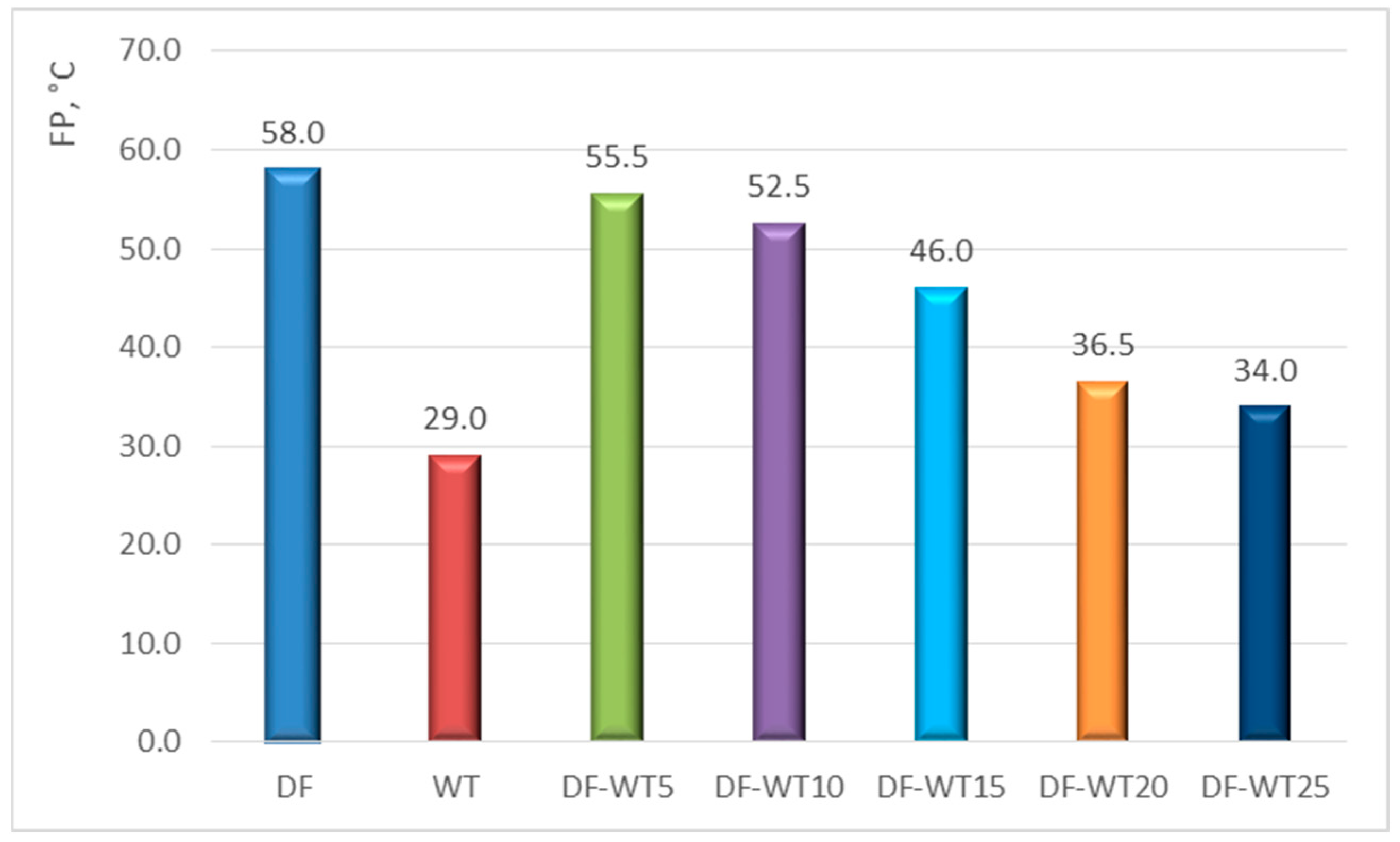
  • Flash point determination—HFP 339; Petroleum Analyzer Company; Houston, TX, USA;
  • Cold filter plugging point determination—FPP 5 Gs; Petroleum Analyzer Company; Houston, TX, USA;
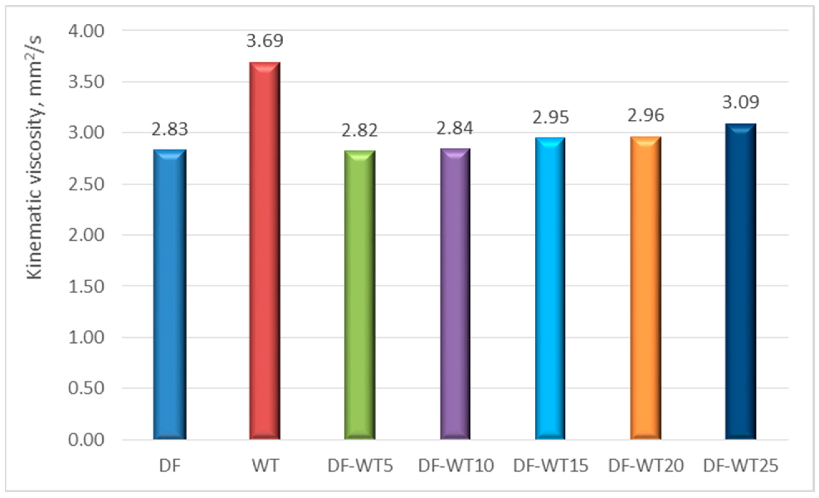
  • Determination of kinematic viscosity at 40 °C—HVU 482; Petroleum Analyzer Company; Houston, TX, USA;
  • Heating value designation—IKA C5000; IKA-Werke GmbH & Co. KG; Staufen, Germany;
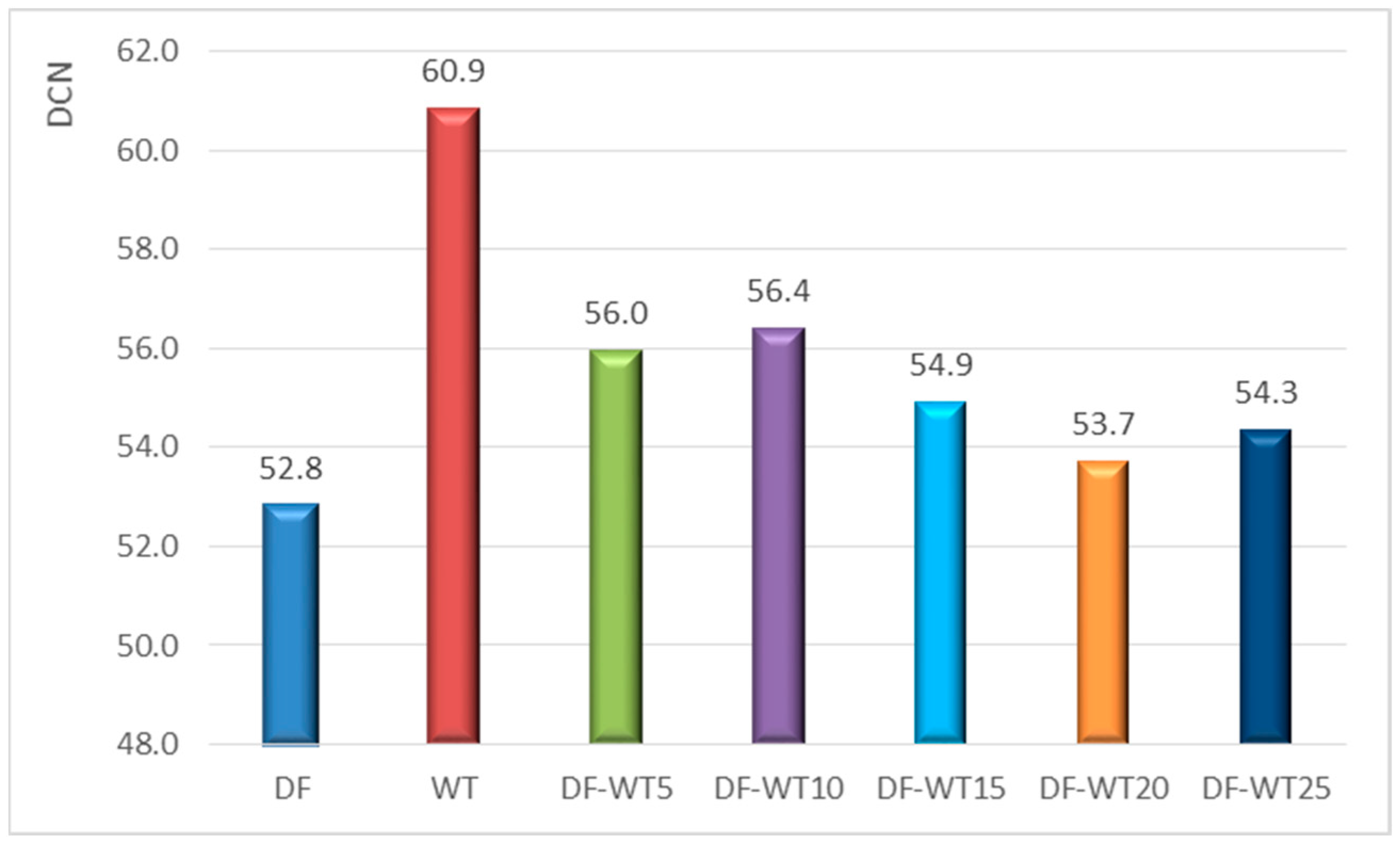
  • Determination of derived cetane number—Cetane ID510; Petroleum Analyzer Company; Houston, TX, USA;
  • Lubricity—HFRR PCS Instruments; PCS Instruments Ltd; London, UK;
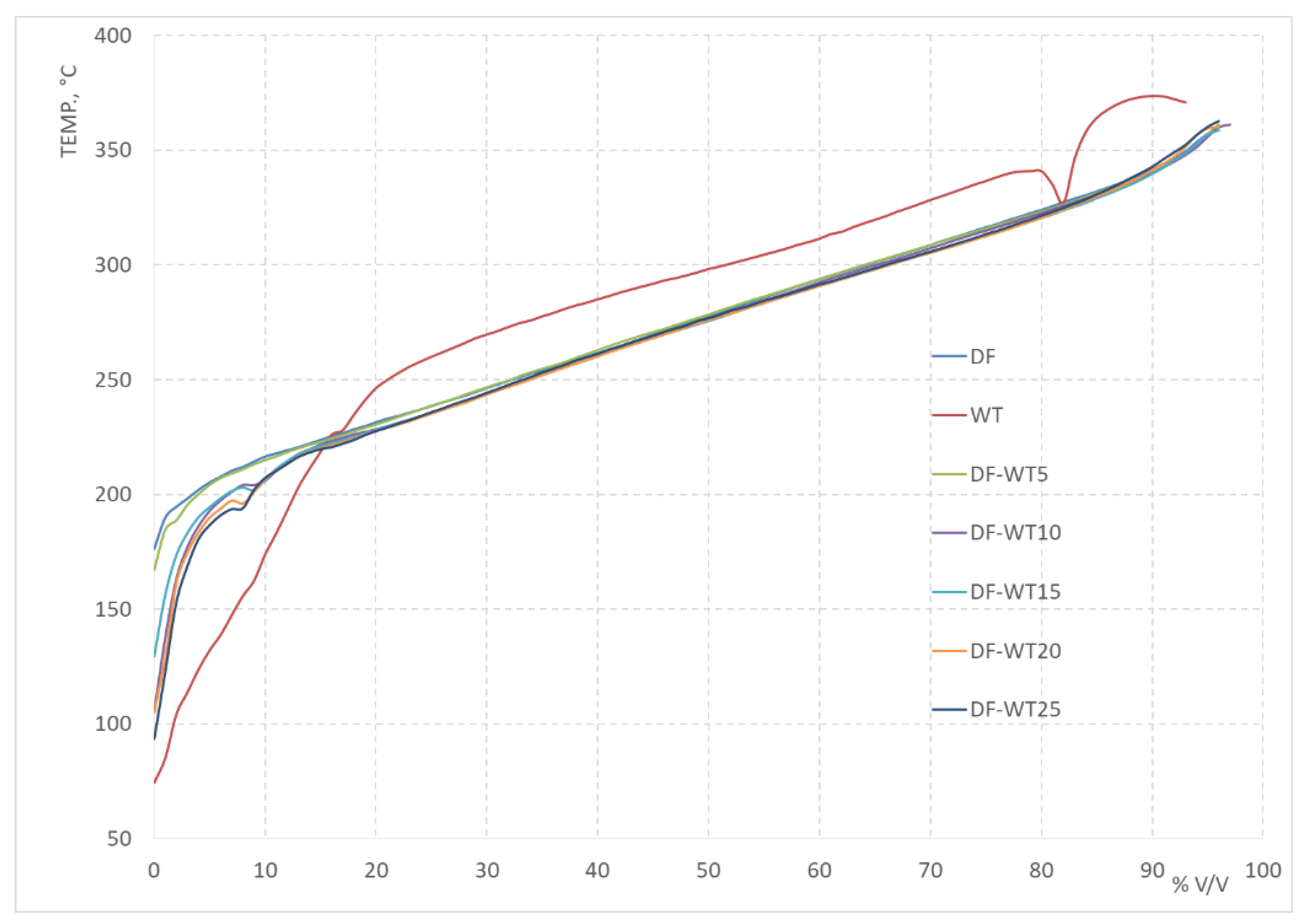
  • Determination of fractional composition (including determination of distillation curve)—OpiDist; Petroleum Analyzer Company; Houston, TX, USA;
  • Sulfur content determination—ANTEK MultiTek; Petroleum Analyzer Company; Houston, TX, USA;
  • Elemental analysis using the VARIO EL III (CHNS method).; Elementar Analysensysteme GmbH; Langenselbold, Germany
The designations of the test samples were adopted as shown in Table 1.
In addition to the determination of physicochemical parameters, the operational and environmental parameters of a diesel engine with a common rail (CR) injection system fueled with DF and DF-WT blends were studied. Selected data of the test engine are included in Table 2, and a view of it is shown in Figure 1. The purpose of the measurements carried out on the engine dynamometer was to determine the power characteristics of the engine, measure the emissions of HCs, NOx nitrogen oxides and PM in the engine exhaust.
NOx concentration in the exhaust gas was measured using a PIERBURG CLD PM-2000 (Pierburg GMBH; Neuss, Germany) exhaust gas analyzer. The concentration of hydrocarbons was measured using a PIERBURG FID PM-2000 (Pierburg GMBH; Neuss, Germany) analyzer. The PIERBURG PTP 2000 (Pierburg GMBH; Neuss, Germany) measurement system is used to determine the mass of PM emitted from diesel engines based on a gravimetric measurement method. The system consists of: a minitunnel with sampling system (an exhaust gas sampling probe, a minitunnel with a heating system, particulate filters, a sample dilution air supply system, a minitunnel flushing system, and sampling probes) and a control cabinet (a PSE 2000 central unit controlling the test system and result acquisition, sample air supply module, and main flow system with vacuum pump). The system makes it possible to accurately determine the amount of diluted exhaust gas flowing through two pairs of measuring filters (on a Teflon substrate). The measurement was made for each operating point of the engine. Before the measurement, the filters were conditioned and their weight determined using a precision scale (laboratory scale type WAA 40/160/X/1). The filters were then placed into the system (two filters per measurement). During the measurement, exhaust gas of a certain temperature range and a certain dilution flows through the filters. The dilution was chosen to keep the temperature of the diluted exhaust gas at 52 ± 3 °C. The measurement time was chosen so that the mass of PM accumulated on the filters is not too small and so that the filters do not become too clogged, which is manifested by a pressure drop greater than 250 kPa. After measuring and reconditioning the filters, they were subject to weighing. The PM weight was calculated as a difference in the weights before and after the measurement. The weight of the filters was then entered into the system and, using Formulas (1)–(4) [33] with the parameter values measured by the system, the specific emission of particulate matter in the exhaust gas was calculated.
Determination of the GEDF (diluted exhaust mass flow rate) was carried out according to the formula:
G EDF = G EXH · q
where:
  • GEXH—mass flow rate of exhaust gas in the exhaust system [kg/h];
  • q—degree of dilution.
The determination of the degree of dilution was calculated according to the equation:
q = G T O T G T O T G D I L
where:
  • GTOT—diluted exhaust gas flow [dm3/min];
  • GDIL—dilution air flow [dm3/min].
The calculation of the particulate mass flow rate in the PMmass test was carried out using the formula:
P M m a s s = M P M M S A M · G E D F 1000
where:
  • MPM—mass of particulate matter accumulated on the measurement filter [mg];
  • MSAM—mass of diluted exhaust gas that flowed through the filter in the test [kg].
Particulate-specific emissions PM [g/kWh] were calculated with this equation:
P M = P M m a s s N e
where:
  • Ne—brake power of the engine at the selected measurement point [kW].
The values of emission mass flow rates of individual pollutants (NOx, HC) were calculated from the formula [33]:
m g a s = u g a s · c g a s · G EXH
where:
  • mgas—emission mass flow rates [g/h] of individual pollutants (NOx, HC);
  • ugas—the ratio between the density of the exhaust gas component and the density of the exhaust gas [–] (for NOx ugas = 0.001587; for HC ugas = 0.00479);
  • cgas—the concentration of a pollutant in the exhaust gas [ppm].
The value of specific emissions of NOx [g/kWh] and HC [g/kWh] was calculated from Equation (6) [33]:
NOx = m NOx N e ;   HC = m H C N e
An electronic scale, WPT-6 with an RS 232 interface, and a measuring device that takes measurements at time intervals of 30 s were used to measure fuel consumption using the mass method. Specific fuel consumption (SFC) was calculated by dividing the value of the mass of hourly fuel consumption [g/h] at a given measurement point by the brake engine power [kW]. A Sensyflow P-Tube flow meter was used to measure the mass of air flowing into the engine cylinder per unit time. Exhaust opacity was measured using a Hartridge analyzer. The essential operating parameters of the injection system, such as injection pressure, advance angle and injection time, were determined according to the data in Table 3. These values correspond to the smoke opacity of the exhaust gas at the specified operating points at 25 HRT (Hartridge percentage scale of smoke).

3. Results and Discussion

As a result of the conducted research, which included measurements of the physical and chemical properties of the synthetic fuel and its blends with DF, as well as tests on an engine dynamometer, a very large amount of data was acquired, which is synthetically presented in the following section of the article.

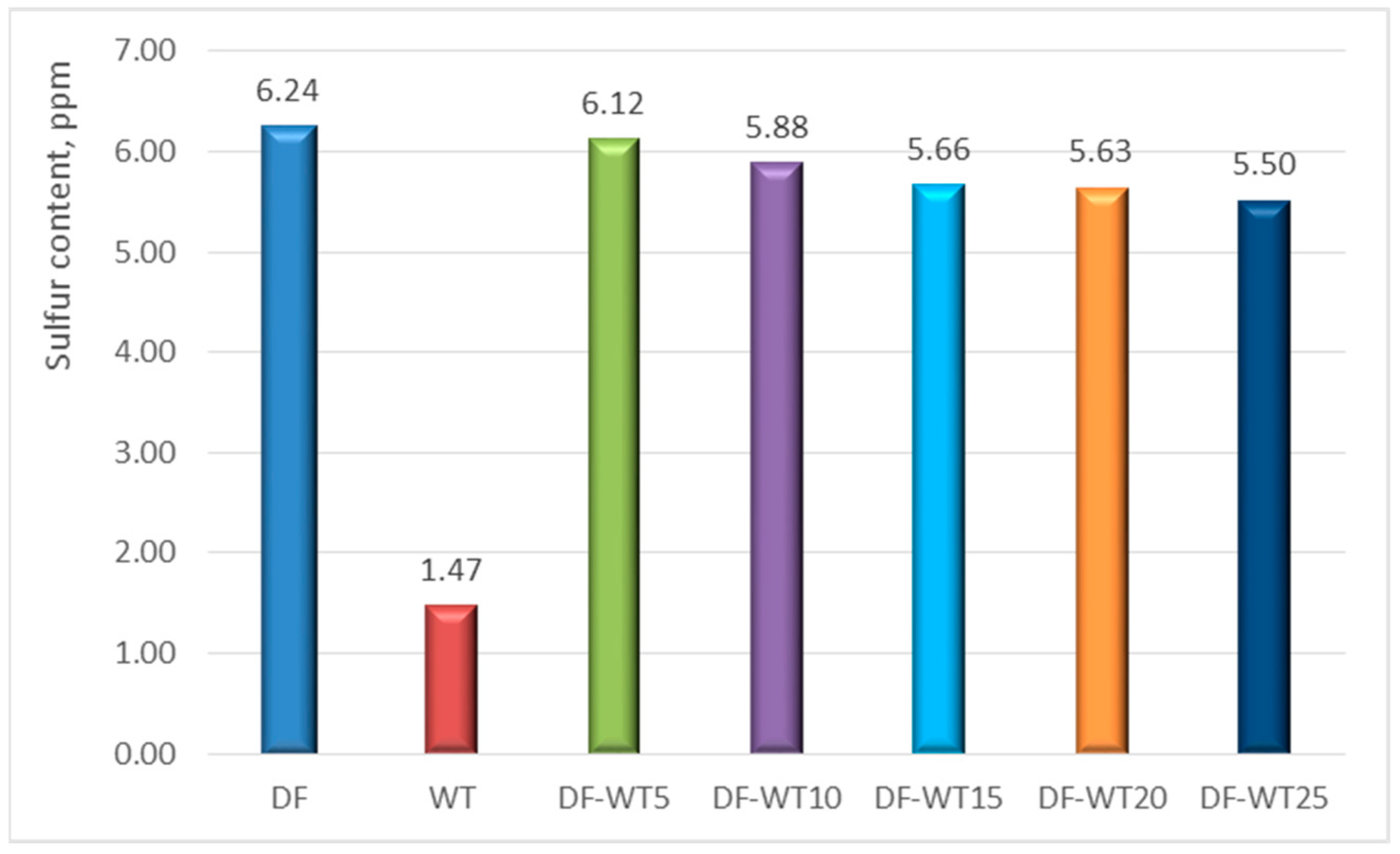
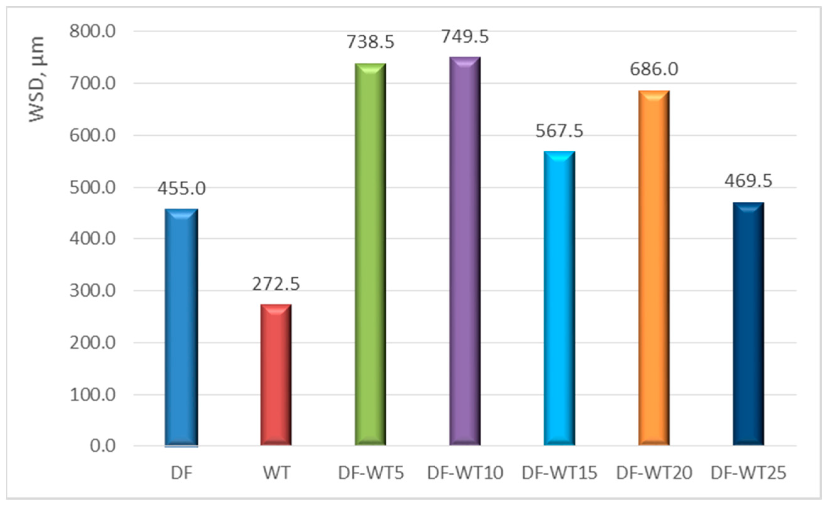
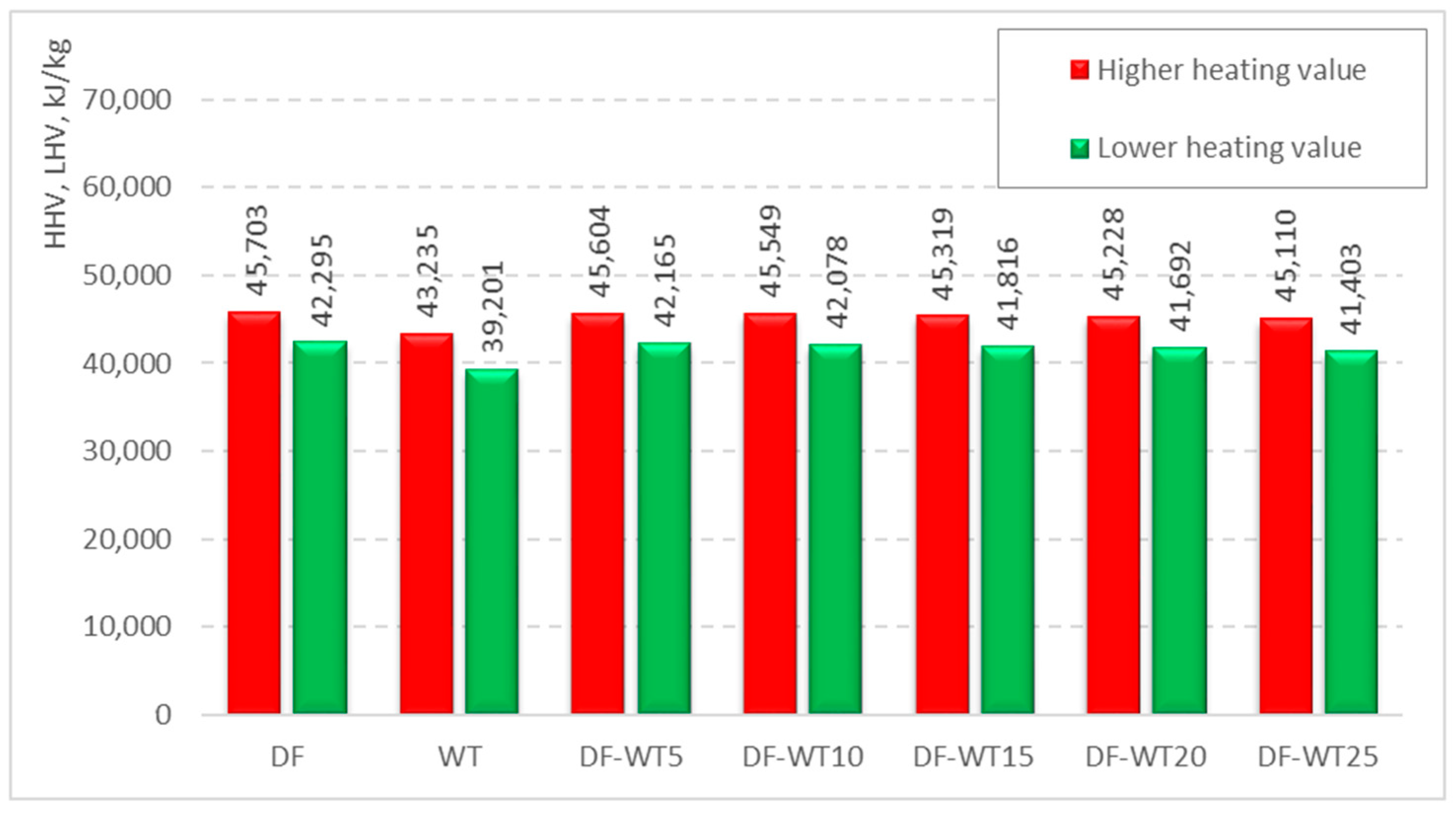
3.1. Results of Physicochemical Tests

Elemental analysis of the fuels was carried out using the VARIO EL III apparatus (CHNS method). The results of these tests are included in Table 4. The elemental analysis showed that WT fuel differs slightly in terms of the proportion of carbon and hydrogen; it contains less carbon and more hydrogen compared to diesel fuel.
The sulfur content of the WT fuel was, after elemental analysis indicated the absence of this element, reexamined using a dedicated ANTEK MultiTek fuel sulfur determination apparatus with a higher measurement sensitivity.
After re-determining the sulfur in the fuels tested (Figure 2), the WT fuel was found to contain nearly 1.5 ppm of sulfur compared to more than 6 ppm in the DF.
The lubricity of the WT fuel, expressed in terms of WSD (wear scar diameter), is a parameter that clearly distinguishes it from commercial DF. Indeed, WT is characterized by a WSD index nearly twice as small as for DF (Figure 3). During the lubricity test, a 5% addition of the new fuel already caused an increase in the average abrasion diameter to a value of about 730 µm. The highest WSD value was achieved for DF-WT10 fuel, which was about 765 µm. Compared to the WSD value for DF, which was about 459 µm, this was an increase of about 70%. When the pure WT fuel was tested, the WSD value was the lowest, at about 270 µm.
The calorific value of the WT fuel (Figure 4) is about 8% lower than that of the DF. As the concentration of the WT in the blends increased, there was a decrease in the heating value of the blend.
The density of the WT fuel is slightly higher than that of the DF (Figure 5); this is a difference of the order of 1%. Regarding this parameter, an increase in the addition of WT to DF resulted in an increase in the density of the blend.
Analogous to density, kinematic viscosity (Figure 6) also increased with increasing synthetic fuel addition to the blend, with WT viscosity being as much as 30% higher than that of DF.
One of the parameters that most differentiates the new fuel from commercial DF is the cold filter plugging point (CFPP) (Figure 7), as it is as high as +3 °C for the pure WT fuel, while the value for diesel is −18 °C. This parameter retained the characteristic of additivity in the tested blends. The addition of 5% caused a slight decrease in the CFPP value, but for a 25% blend this parameter increased by 50%, i.e., to a value of −9 °C.
Analysis of the distillation curve (Figure 8) shows that the new synthetic fuel has more low-boiling hydrocarbon fractions, as it has already distilled about 10% of the fuel sample volume at 150 °C. After distilling about 20% of the fuel volume, another difference in the fractional composition between WT and DF can be seen. Indeed, one can clearly see the share of heavier fractions in the new fuel, which distils at higher temperatures than in DF. On the other hand, the effect of the addition of synthetic fuel to DF on the distillation curve is noticeable only until about 20% of the volume of the test sample is distilled.
Tests of the derived cetane number (DCN) were conducted on an apparatus using the constant volume combustion chamber (CVCC) method. The results of these tests are illustrated in Figure 9. WT fuel had the best self-ignition properties (DCN = 60.9). This was about 8 higher than for DF. This may indicate the high proportion of paraffinic hydrocarbons in WT fuel, which can also be confirmed by the high cold filter locking temperature (CFPP—Figure 7). For DF-WT blends, favorable auto-ignition properties were obtained for these blends, despite the relatively small shares of WT fuel in the blend with DF, for which the DCN value ranged from about 54 (for DF-WT20) to about 56 (for DF-WT5 and DF-WT10).
Figure 10 shows the results of ignition temperature tests of the analyzed fuels. This indicates a higher volatility of the WT fuel for which the FP = 29 °C, which is confirmed by the results of the fractional composition tests shown in Figure 8. An increase in the proportion of WT fuel in the blend with DF resulted in an approximately linear decrease in ignition temperature.

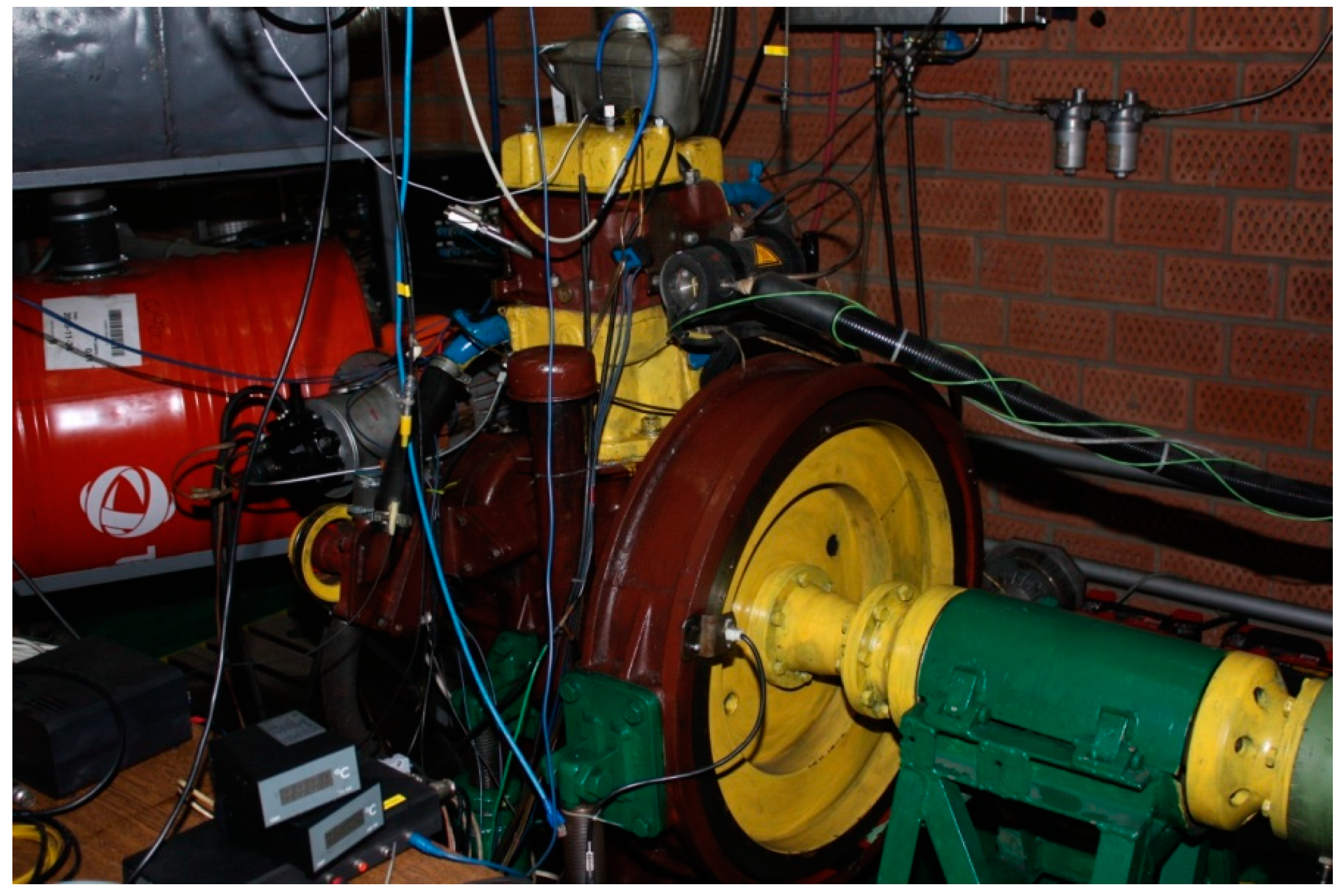
3.2. Results of Tests Carried Out on an Engine Dynamometer

The course of the engine power curve as a function of rotational speed (Figure 11) indicates that the highest values of power were achieved when feeding DF. The smallest power values at the tested engine operating points were obtained when the engine was fueled with a 15% blend, while for higher rotational speeds the highest values of usable power obtained with the blends were registered for the fuels DF-WT25, DF-WT10 and DF-WT20. At lower rotational speeds, the differences were no longer so noticeable, except for the 15% blend, for which 12 kW was registered.
Considering specific fuel consumption (Figure 12), the smallest values were obtained for DF, and the largest for DF-WT15.
The concentration of nitrogen oxides (Figure 13) when feeding the engine with DF was, on average, 10–40% higher than the concentration obtained when burning the DF-WT blends. Only for an engine speed of 1000 rpm did the DF-WT15 blend show a higher NOx concentration value than for DF. Large differences in the concentration of NOx in the exhaust gas during the combustion of the blends were not recorded; only for a rotational speed of 1800 rpm did the DF-WT25 fuel show a concentration greater by more than 50% than the average for the blends. When converted to specific NOx emissions (Figure 14), the difference between DF and the blends turned out to be much smaller, and for the 5% blend, at rotational speeds of 1400 and 1600 rpm, an engine fueled by DF had only slightly lower emissions.
Regarding the concentration of HC (Figure 15), much lower values were obtained when the engine was fed with DF-WT blends in relation to the diesel fuel. The lowest concentration value at about 50–70 ppm, was obtained for an engine fueled by a blend with a 15% share of WT. For smaller and larger shares of WT fuel, HC concentration values increased. After converting the concentrations into specific emissions of HC (Figure 16), it turned out that the minimum values were obtained for blends of 10 and 15%. In addition, for the 5% blend, the difference between HC emissions achieved on this fuel and those achieved on DF decreased.
Specific PM emissions (Figure 17) were found to be highest for DF-WT15 fuel and lowest for DF-WT5; the difference was more than 300%. Only when the test engine was run on a 5% blend were PM emissions that were lower than for DF obtained.
For each operating point, as assumed for a given speed, the injection advance angle and injector opening time were constant. The recorded differences with respect to a given parameter for each of the tested fuels, were due to different physicochemical properties. This entailed varying conditions for the formation of the combustible mixture, which in turn affected the course of the combustion process. As shown in Figure 9, the analyzed samples had different self-ignition properties, which translated into the amount of fuel accumulated in the combustion chamber during the ignition delay period. This resulted in changes with regard to the course of pressure changes in the kinetic combustion phase and, therefore, also with regard to the emitted pollutants and the effective parameters of the engine. The second important parameter affecting the formation of the combustible mixture and therefore the course of the combustion process was the kinematic viscosity of the fuel (Figure 6). This parameter is one of the key parameters affecting the secondary disintegration of droplets (higher kinematic viscosity results in an increase in droplet diameter), which naturally changes the combustion conditions resulting from changes in the time required for the evaporation of the fuel droplets.

4. Conclusions

The physicochemical studies of the properties of the new fuel and the dynamometer tests conducted provided major results. The parameters of synthetic fuel obtained from tires in most cases differ slightly from those of commercial diesel fuel. After analyzing the test results, the following conclusions can be made:
  • The physicochemical parameters of WT fuel mostly differ slightly from the corresponding parameters for DF; the biggest differences are in the derived cetane number DCN (about 61 for WT fuel and about 53 for DF); another parameter that significantly differentiates the two fuels is the CFPP (+3 °C for WT fuel and −18 °C for DF);
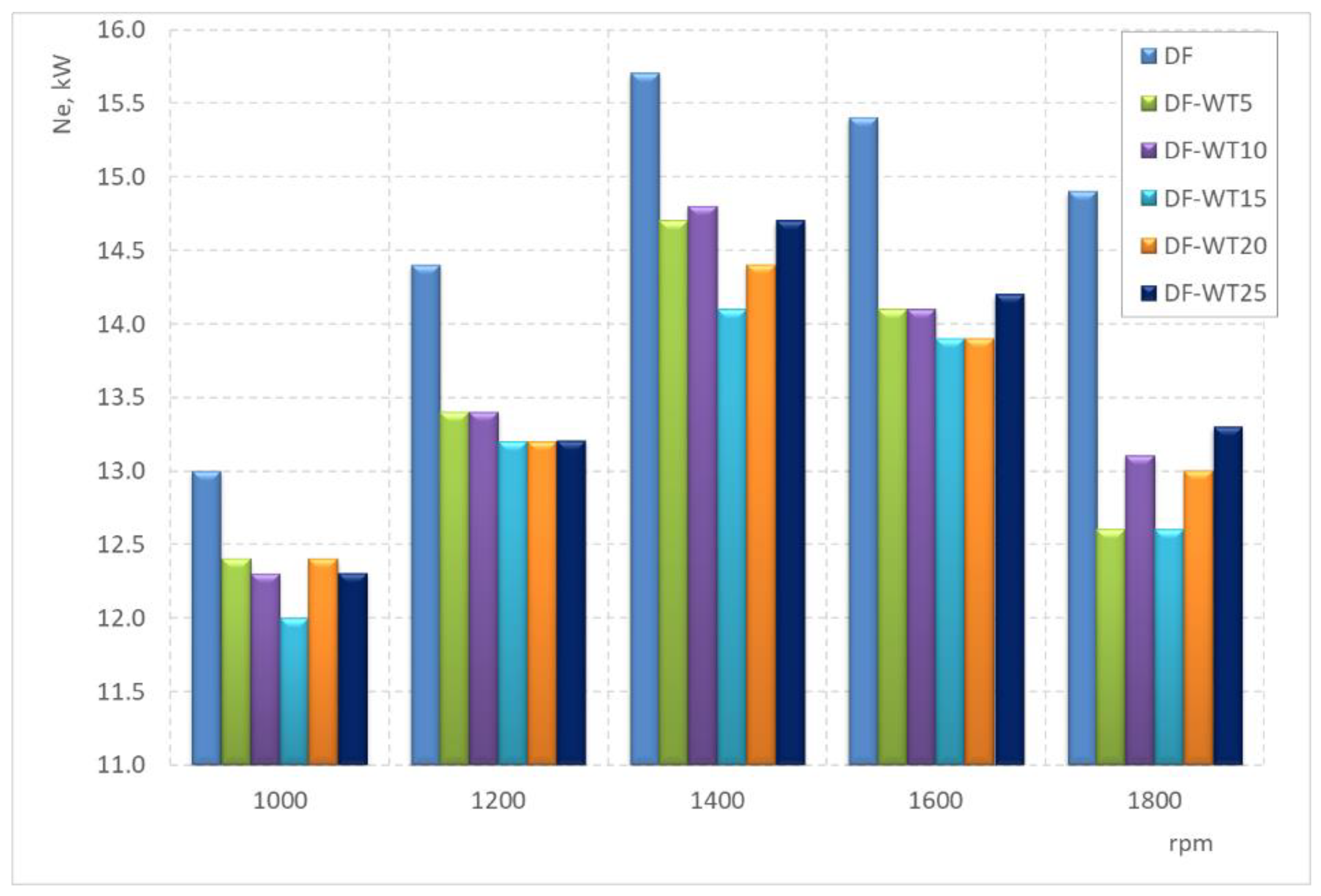
  • The least favorable properties in terms of the obtained operational parameters are characterized by the DF-WT15 fuel; the biggest difference in the value of the obtained power is about 20%;
  • Among the blends, DF-WT10 has the most favorable properties in terms of operational parameters;
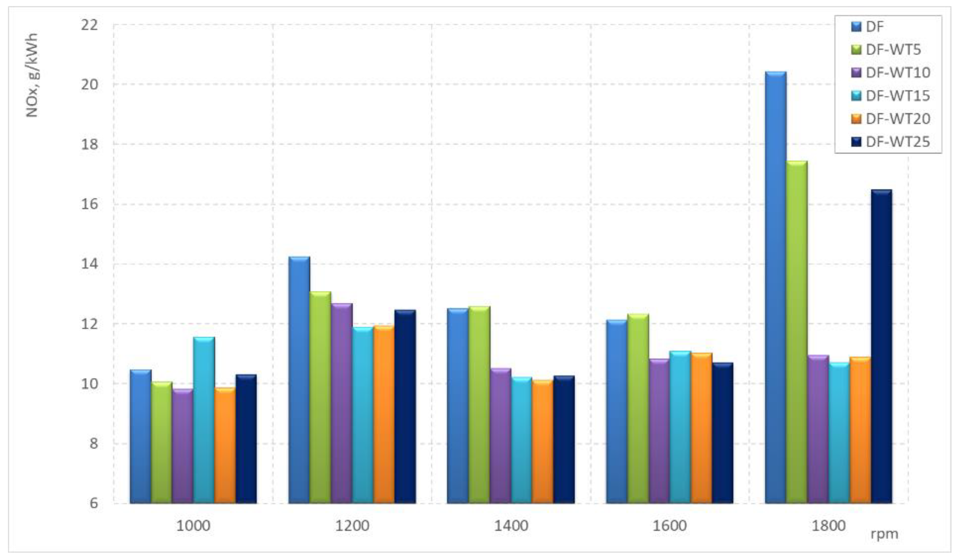
  • The NOx concentrations in the exhaust gas when the engine was fueled with DF-WT blends were about 15% lower (on average for all blends) than the NOx concentrations obtained when fueled with pure DF;
  • The values of specific emissions of NOx, for average rotational speeds (1200–1600 rpm), when fed on DF were about 25% lower than for the blends; only the DF-WT5 fuel was characterized, at some measurement points (1400 and 1600 rpm), by specific emissions of NOx slightly higher than on a DF-powered engine;
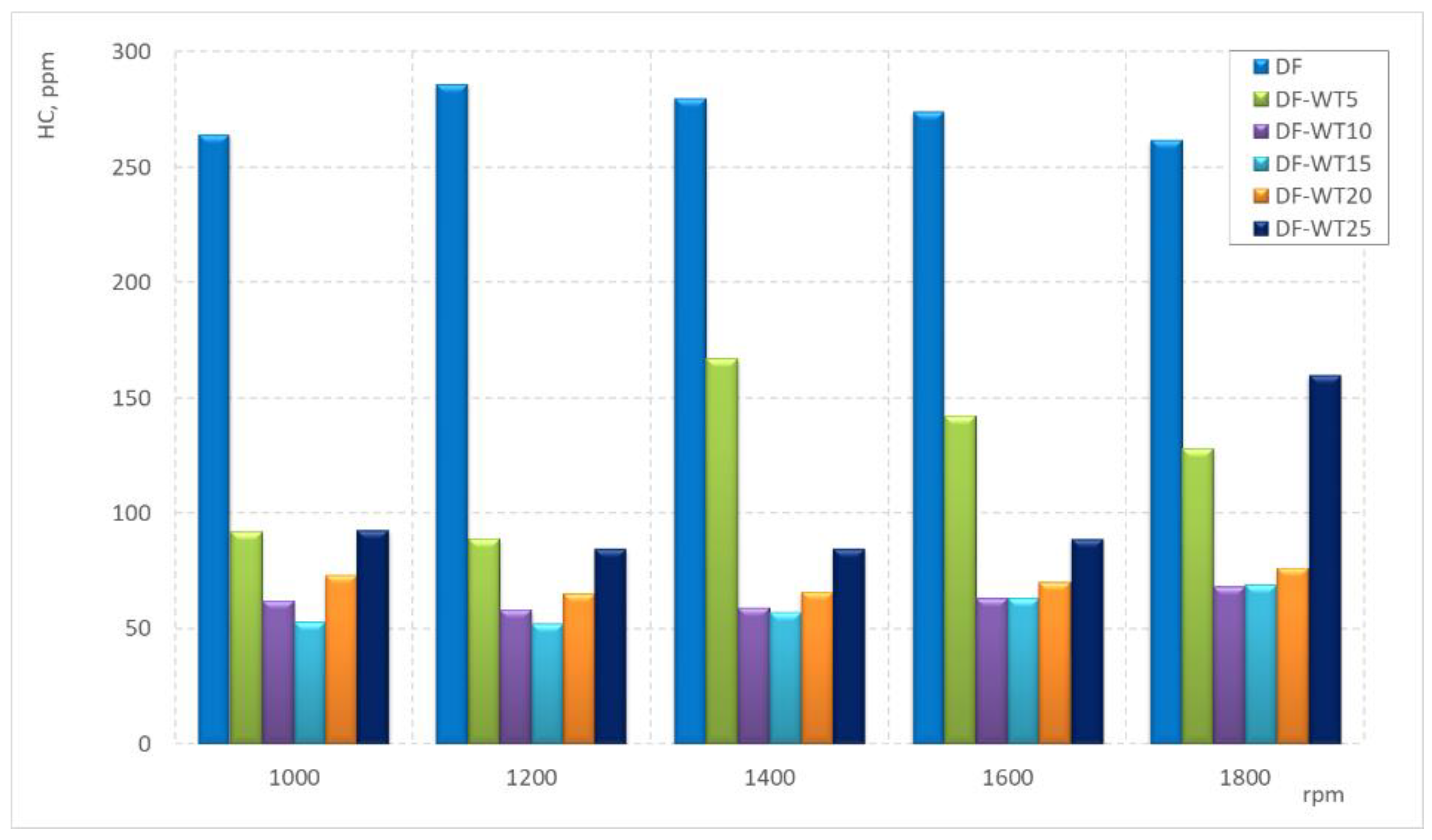
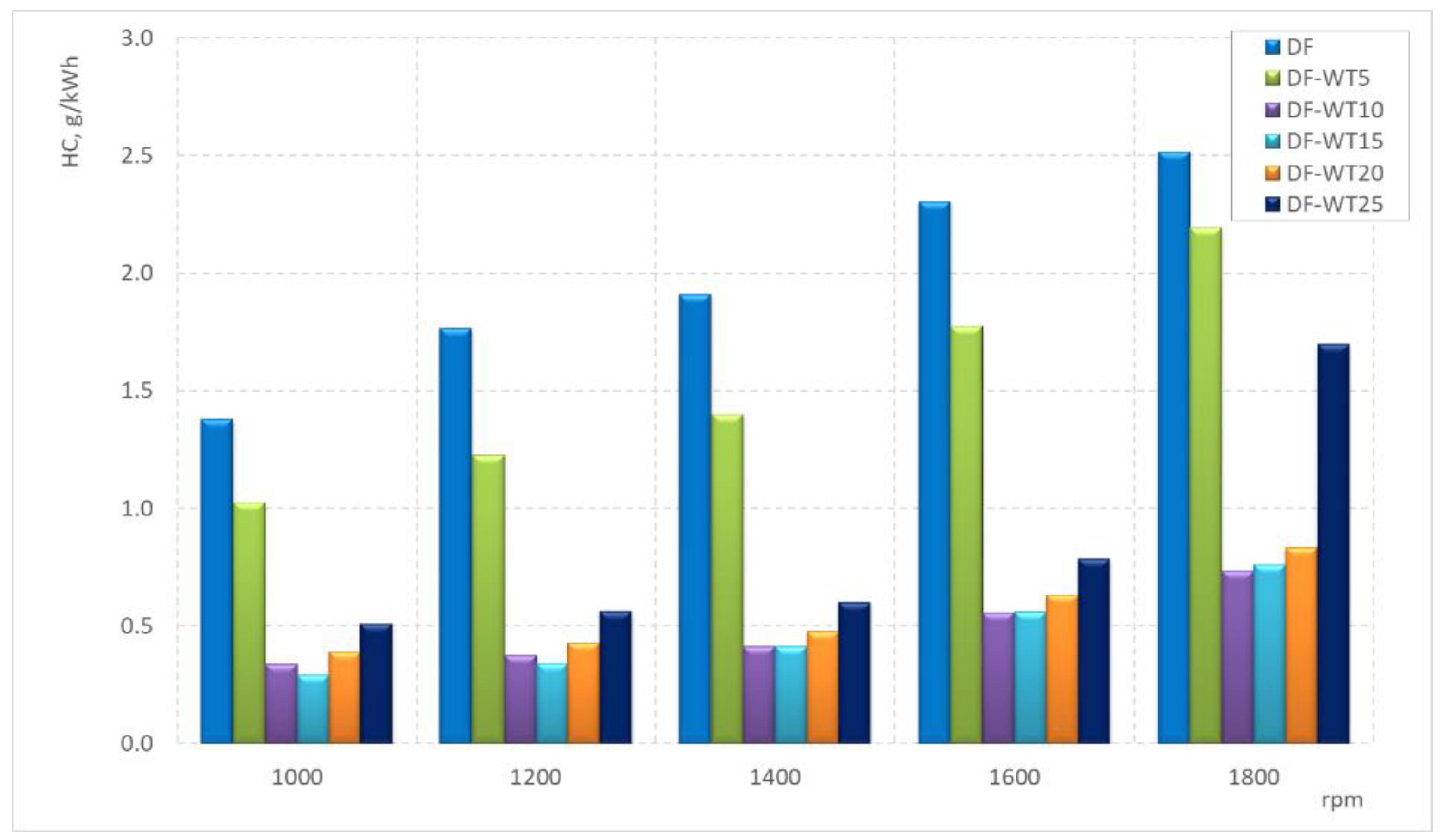
  • The lowest concentration of HCs for the tested speeds was recorded when the engine was fueled with the DF-WT15 fuel;
  • After exceeding 5% of WT fuel in the blend, there is a sharp reduction in specific HC emissions in the tested speed range;
  • Knowledge of the selected parameters of pure synthetic WT fuel can be used for the design of fuel apparatus components, with this being both the appropriate selection of materials and the technology of the surface layer; some parameters of the new fuel (e.g., lubricity) differ significantly in value to commercial diesel fuel.
Considering the use of fuel derived from used car tires as a component of diesel fuel, it is important to consider the studies conducted by the authors in the wide range of physicochemical parameters analyzed. The results on the self-ignition properties of the blends analyzed, using a normative procedure based on the CVCC method, should be considered particularly important. The authors are not aware of the results of other studies in this area.
The research conducted indicates the need for further work aimed at gaining a closer understanding of the effects on engine performance of the fuels in question. In doing so, it is necessary to take into account, first of all, different engine loads and different operating parameters of the tray injection system. It is the intention of the authors to continue work in this area.

Author Contributions

Conceptualization, M.J., A.J., H.K. and K.B.; methodology, M.J., H.K. and K.B.; software, K.B.; validation, M.J., A.J., H.K. and K.B.; formal analysis, A.J. and H.K.; investigation, M.J., H.K. and K.B.; resources, M.J., A.J., H.K. and K.B.; data curation, M.J.; writing—original draft preparation, M.J., A.J., H.K. and K.B.; writing—review and editing, M.J., A.J., H.K. and K.B.; visualization, M.J.; supervision, A.J. and H.K. All authors have read and agreed to the published version of the manuscript.

Funding

This research received no external funding.

Institutional Review Board Statement

Not applicable.

Informed Consent Statement

Not applicable.

Data Availability Statement

Data are contained within the article.

Acknowledgments

The authors wish to acknowledge the Polish Ministry of Education and Science and the Rzeszow University of Technology for supporting this research.

Conflicts of Interest

The authors declare no conflicts of interest.

Abbreviations

CFPPCold filter plugin point
cgasThe concentration of a pollutant in the exhaust gas
CLDChemi-luminescence detector
COCarbon monoxide
CO2Carbon dioxide
CRCommon rail
DFDiesel fuel
DTPODistilled tire pyrolysis oil
FIDFlame ionization detector
FPFlash point
GDILDilution air flow
GEFDDiluted exhaust mass flow rate
GEXHMass flow rate of exhaust gas in the exhaust system
GTOTDiluted exhaust gas flow
HCHydrocarbons
HHVHigher heating value
HRTHartridge percentage scale of smoke
ICInternal combustion engine
LHVLower heating value
mgasEmission mass flow rates of individual pollutants
MPMMass of particulate matter accumulated on the measurement filter
MSAMMass of diluted exhaust gas that flowed through the filter in the test
NDIRNon-dispersive infrared
NeBrake power of the engine
NOxNitrogen oxides
PMParticulate matter
PMmassParticulate mass flow rate
qDegree of dilution
SOXSulfur oxides
TDOTire-derived oil
THCTotal hydrocarbons
TPOTire pyrolysis oil
ugasThe ratio between the density of the exhaust gas component and the density of the exhaust gas
WTWaste tires

References

  1. Tutak, W.; Jamrozik, A. Comparative Analysis of Combustion Stability of Diesel/Ethanol Utilization by Blend and Dual Fuel. Processes 2019, 7, 946. [Google Scholar] [CrossRef]
  2. Kuszewski, H.; Jaworski, A.; Mądziel, M.; Woś, P. The investigation of auto-ignition properties of 1-butanol–biodiesel blends under various temperatures conditions. Fuel 2023, 346, 128388. [Google Scholar] [CrossRef]
  3. Kim, H.Y.; Ge, J.C.; Choi, N.J. Effects of Ethanol–Diesel on the Combustion and Emissions from a Diesel Engine at a Low Idle Speed. Appl. Sci. 2020, 10, 4153. [Google Scholar] [CrossRef]
  4. Kuszewski, H.; Jaworski, A.; Ustrzycki, A.; Lejda, K.; Balawender, K.; Woś, P. Use of the constant volume combustion chamber to examine the properties of autoignition and derived cetane number of mixtures of diesel fuel and ethanol. Fuel 2017, 200, 564–575. [Google Scholar] [CrossRef]
  5. Tutak, W.; Jamrozik, A.; Grab-Rogaliński, K. The Effect of RME-1-Butanol Blends on Combustion, Performance and Emission of a Direct Injection Diesel Engine. Energies 2021, 14, 2941. [Google Scholar] [CrossRef]
  6. Corsini, A.; Marchegiani, A.; Rispoli, F.; Sciulli, F.; Venturini, P. Vegetable Oils as Fuels in Diesel Engine. Engine Performance and Emissions. Energy Procedia 2015, 81, 942–949. [Google Scholar] [CrossRef]
  7. Singh, N.K.; Singh, Y.; Kumar, V.; Singh, B. Biodiesel as a potential replacement fuel for CI engine to meet the sustainability criteria: A review. Mater. Today Proc. 2023. [Google Scholar] [CrossRef]
  8. Hunicz, J.; Matijošius, J.; Rimkus, A.; Kilikevičius, A.; Kordos, P.; Mikulski, M. Efficient hydrotreated vegetable oil combustion under partially premixed conditions with heavy exhaust gas recirculation. Fuel 2020, 268, 117350. [Google Scholar] [CrossRef]
  9. Jaworski, A.; Kuszewski, H.; Longwic, R.; Sander, P. Assessment of Self-Ignition Properties of Canola Oil–n-Hexane Blends in a Constant Volume Combustion Chamber and Compression Ignition Engine. Appl. Sci. 2023, 13, 10558. [Google Scholar] [CrossRef]
  10. Sudharshan Ravi, S.; Mazumder, J.; Sun, J.; Brace, C.; Turner, J.W.G. Techno-Economic assessment of synthetic E-Fuels derived from atmospheric CO2 and green hydrogen. Energy Convers. Manag. 2023, 291, 117271. [Google Scholar] [CrossRef]
  11. Baensch-Baltruschat, B.; Kocher, B.; Stock, F.; Reifferscheid, G. Tyre and road wear particles (TRWP)—A review of generation, properties, emissions, human health risk, ecotoxicity, and fate in the environment. Sci. Total Environ. 2020, 733, 137823. [Google Scholar] [CrossRef]
  12. Jaworski, A.; Balawender, K.; Kuszewski, H.; Jaremcio, M. The Assessment of PM2.5 and PM10 Immission in Atmospheric Air in a Climate Chamber during Tests of an Electric Car on a Chassis Dynamometer. Atmosphere 2024, 15, 270. [Google Scholar] [CrossRef]
  13. Zerin, N.H.; Rasul, M.G.; Jahirul, M.I.; Sayem, A.S.M. End-of-life tyre conversion to energy: A review on pyrolysis and activated carbon production processes and their challenges. Sci. Total Environ. 2023, 905, 166981. [Google Scholar] [CrossRef]
  14. Thomas, B.S.; Gupta, R.C. Properties of high strength concrete containing scrap tire rubber. J. Clean. Prod. 2016, 113, 86–92. [Google Scholar] [CrossRef]
  15. Martínez, J.D.; Puy, N.; Murillo, R.; García, T.; Navarro, M.V.; Mastral, A.M. Waste tyre pyrolysis—A review. Renew. Sustain. Energy Rev. 2013, 23, 179–213. [Google Scholar] [CrossRef]
  16. Han, W.; Han, D.; Chen, H. Pyrolysis of Waste Tires: A Review. Polymers 2023, 15, 1604. [Google Scholar] [CrossRef] [PubMed]
  17. Wang, W.-C.; Bai, C.-J.; Lin, C.-T.; Prakash, S. Alternative fuel produced from thermal pyrolysis of waste tires and its use in a DI diesel engine. Appl. Therm. Eng. 2015, 93, 330–338. [Google Scholar] [CrossRef]
  18. Kapilan, N.; Jullya, N. Studies on Improvement of Performance of Compression Ignition Engine Fuelled with Mixture of Honge Biodiesel and Tire Pyrolysis Oil, Strojnícky časopis. J. Mech. Eng. 2018, 68, 15–24. [Google Scholar] [CrossRef]
  19. Yaqoob, H.; Teoh, Y.H.; Jamil, M.A.; Gulzar, M. Potential of tire pyrolysis oil as an alternate fuel for diesel engines: A review. J. Energy Inst. 2021, 96, 205–221. [Google Scholar] [CrossRef]
  20. Islam, M.N.; Nahian, M.R. Improvement of Waste Tire Pyrolysis Oil and Performance Test with Diesel in CI Engine. J. Renew. Energy 2016, 2016, 5137247. [Google Scholar] [CrossRef]
  21. Khairil; Rickansvar, M.; Mubarak, A.; Sofyan, S. Experimental study the effect of diesel engine performance fuelled by waste tire oil- dexlite blends. BIO Web Conf. 2023, 62, 04003. [Google Scholar] [CrossRef]
  22. Akhil, M.; Saikat, D.; Saravanan, B.; Vasudeva, M. Liquid fuel from waste tires: Novel refining, advanced characterization and utilization in engines with ethyl levulinate as an additive. RSC Adv. 2021, 11, 9807–9826. [Google Scholar] [CrossRef]
  23. İlkılıç, C.; Aydın, H. Fuel production from waste vehicle tires by catalytic pyrolysis and its application in a diesel engine. Fuel Process. Technol. 2011, 92, 1129–1135. [Google Scholar] [CrossRef]
  24. Kapilan, N.; Kumar, K.A.; Chandra, B.P.H. Studies on Pyrolysis Oil derived from waste Tires as Fuel for Diesel Engine. J. Phys. Conf. Ser. 2021, 2070, 012232. [Google Scholar] [CrossRef]
  25. Doğan, O.; Çelik, M.B.; Özdalyan, B. The effect of tire derived fuel/diesel fuel blends utilization on diesel engine performance and emissions. Fuel 2012, 95, 340–346. [Google Scholar] [CrossRef]
  26. Marshal, S.J.J.; Samuel, S.Y.; Sundari, K.G.; Rajamohan, S. 4—Diesel engine performance and emissions with fuels derived from waste tyres. In Advanced Technology for the Conversion of Waste into Fuels and Chemicals; Khan, A., Pizzi, A., Jawaid, M., Azum, N., Asiri, A., Isa, I., Eds.; Woodhead Publishing: Cambridge, UK, 2021; pp. 69–92. ISBN 9780323901505. [Google Scholar] [CrossRef]
  27. Jahirul, M.I.; Hossain, F.M.; Rasul, M.G.; Chowdhury, A.A. A Review on the Thermochemical Recycling of Waste Tyres to Oil for Automobile Engine Application. Energies 2021, 14, 3837. [Google Scholar] [CrossRef]
  28. Mello, M.; Rutto, H.; Seodigeng, T. Waste tire pyrolysis and desulfurization of tire pyrolytic oil (TPO)—A review. J. Air Waste Manag. Assoc. 2023, 73, 159–177. [Google Scholar] [CrossRef]
  29. Hossain, F.M.; Nabi, M.N.; Rainey, T.J.; Bodisco, T.; Bayley, T.; Randall, D.; Ristovski, Z.; Brown, R.J. Novel biofuels derived from waste tyres and their effects on reducing oxides of nitrogen and particulate matter emissions. J. Clean. Prod. 2020, 242, 118463. [Google Scholar] [CrossRef]
  30. Pote, R.N.; Patil, R.K. Combustion and emission characteristics analysis of waste tyre pyrolysis oil. SN Appl. Sci. 2019, 1, 294. [Google Scholar] [CrossRef]
  31. Mikulski, M.; Ambrosewicz-Walacik, M.; Hunicz, J.; Nitkiewicz, S. Combustion engine applications of waste tyre pyrolytic oil. Prog. Energy Combust. Sci. 2021, 85, 100915. [Google Scholar] [CrossRef]
  32. Kumaravel, S.T.; Murugesan, A.; Kumaravel, A. Tyre pyrolysis oil as an alternative fuel for diesel engines—A review. Renew. Sustain. Energy Rev. 2016, 60, 1678–1685. [Google Scholar] [CrossRef]
  33. Directive 2005/55/EC; Directive 2005/55/EC of the European Parliament and of the Council of 28 September 2005 on the Approximation of the Laws of the Member States Relating to the Measures to Be Taken against the Emission of Gaseous and Particulate Pollutants from Compression-Ignition Engines for Use in Vehicles, and the Emission of Gaseous Pollutants from Positive-Ignition Engines Fuelled with Natural Gas or Liquefied Petroleum Gas for Use in Vehicles. European Union: Maastricht, The Netherlands, 2005. Available online: https://eur-lex.europa.eu/legal-content/EN/ALL/?uri=CELEX%3A32005L0055 (accessed on 8 July 2024).
Figure 1. The tested engine on the dynamometer bench.
Sustainability 16 06404 g001
Figure 2. The sulfur content of the tested fuels.
Sustainability 16 06404 g002
Figure 3. The wear scar diameter of the tested fuels.
Sustainability 16 06404 g003
Figure 4. The higher heating value (HHV) and lower heating value (LHV) of the tested fuels.
Sustainability 16 06404 g004
Figure 5. The density of the tested fuels.
Sustainability 16 06404 g005
Figure 6. The kinematic viscosity of the tested fuels.
Sustainability 16 06404 g006
Figure 7. Cold filter plugging point (CFPP) of the tested fuels.
Sustainability 16 06404 g007
Figure 8. The distillation curves of the tested fuels.
Sustainability 16 06404 g008
Figure 9. The derived cetane number (DCN) of the tested fuels.
Sustainability 16 06404 g009
Figure 10. Flash point of the tested fuels.
Sustainability 16 06404 g010
Figure 11. Engine brake power.
Sustainability 16 06404 g011
Figure 12. Specific fuel consumption.
Sustainability 16 06404 g012
Figure 13. The concentration of NOx in the exhaust gas.
Sustainability 16 06404 g013
Figure 14. The specific emission of NOx in the exhaust gas.
Sustainability 16 06404 g014
Figure 15. The concentration of HC in the exhaust gas.
Sustainability 16 06404 g015
Figure 16. The specific emission of HC in the exhaust gas.
Sustainability 16 06404 g016
Figure 17. PM-specific emissions.
Sustainability 16 06404 g017
Table 1. Symbols of fuel samples.
Fuel DescriptionVolume Fraction [%]
Diesel FuelWaste Tire-Derived Fuel
DF1000
WT0100
DF-WT5955
DF-WT109010
DF-WT158515
DF-WT208020
DF-WT257525
Table 2. Parameters of the tested engine.
ParameterValue
Number of cylinders1
Number of strokes4
Cooling typeLiquid
Piston stroke146 mm
Cylinder diameter127 mm
Displacement capacity1850 cm3
Compression ratio15.75
Nominal RPM2200 rpm
Oiling systemcirculation under pressure
Table 3. The control parameters of the tested engine.
L.p.n [rpm]αww
[deg CA before TDC]
tis [µs]pinj [MPa]
1100018350080
2120020310080
3140022295080
4160022250080
5180022210080
Table 4. Results of elemental analysis.
Sample NameComponentNumber
of Analyses
Average Mass Fraction [%]
DFC781.51
H18.48
N0.00 *
S0.00 *
WTC784.38
H16.61
N0.00 *
S0.00 *
* below the lower detection limit.
Disclaimer/Publisher’s Note: The statements, opinions and data contained in all publications are solely those of the individual author(s) and contributor(s) and not of MDPI and/or the editor(s). MDPI and/or the editor(s) disclaim responsibility for any injury to people or property resulting from any ideas, methods, instructions or products referred to in the content.

