Article

Experimental Study on Heat Release Performance for Sorption Thermal Battery Based on Wave Analysis Method

by
Meng Yu
1,2,
Wei Liu
3,
Yuchen Lin
3,
Neng Gao
4,
Xuejun Zhang
3 and
Long Jiang
3,*
1
Special Equipment Safety Supervision and Inspection Institute of Jiangsu Province, Nanjing 210036, China
2
Key Laboratory of Liquid Hydrogen Energy Storage and Transportation Equipment for Jiangsu Province Market Regulation, Nanjing 210036, China
3
Key Laboratory of Refrigeration and Cryogenic Technology of Zhejiang Province, Institute of Refrigeration and Cryogenics, Zhejiang University, Hangzhou 310027, China
4
Institute of Energy and Environment Engineering, NingboTech University, Ningbo 315000, China
*
Author to whom correspondence should be addressed.
Sustainability 2024, 16(15), 6654; https://doi.org/10.3390/su16156654
Submission received: 1 July 2024 / Revised: 31 July 2024 / Accepted: 1 August 2024 / Published: 3 August 2024

Abstract

:
Recent developments in water-based open sorption thermal batteries (STBs) have drawn burgeoning attention due to their advantages of high energy storage density and flexible working modes for space heating. One of the main challenges is how to improve heat release performance, e.g., longer stable heat output and effective output temperature. This paper aims to explore the heat release performance of sorption thermal batteries based on wave analysis methods. Zeolite 13X is used for the experimental investigation in terms of the relative humidity of inlet gas, system air velocity, and the length of the reactor. The results demonstrate that the optimal stable temperature output time of the sorption thermal battery experimental rig is 80 min, and heat release per unit volume reaches 115.6 MJ for the most appropriate reactor length. Thus, the optimal heat release time of the STB under the condition of various relative humidity and air velocities is 152 min and 182 min, respectively, and the corresponding stable heat release could reach 161.1 MJ and 136.5 MJ, respectively. Therefore, the heat release performance of STBs could be adjusted by adopting the wave analysis method, which would facilitate the reactor design and system arrangement.

1. Introduction

With the deep development of multi-energy vectors in the near future, energy storage technologies will play a significant role in adjusting the mismatch between energy supply and energy demands [1,2]. It could be generally classified into mechanical, electrochemical, chemical, and thermal energy storage, etc. [3,4]. The former storage types tend to account for a large proportion of the current energy structure due to technology maturity, economic benefits, and high energy density [5,6]. However, thermal energy storage (TES) could also be valued and gathering momentum since it encompasses quite a few applications, e.g., residential and non-residential buildings as well as districts and urban networks [7,8]. The main types of sensible heat storage (SHS), latent heat storage (LHS), and thermochemical heat storage (THS) have been investigated in different research stages, which are indicated in Table 1 [9,10,11]. It is indicated that SHS is relatively simple, stable, and mature, but it has the lowest energy storage density (ESD), around 0.2 GJ·m−3 [12]. Although the ESD of LHS is about 2–4 times higher than that of SHS, it suffers from low thermal conductivity that influences the charging and discharging rates [13]. Also, both SHS and LHS tend to have large heat loss, which leads to premature heat discharging before the intended period, especially during long-term or seasonal energy storage [14,15].
Compared with SHS and LHS, THS has a high energy density of around 0.7–3.0 GJ·m−3 due to its high reaction enthalpy based on a reversible chemical reaction/sorption process [16]. The typical THS types are chemical reactions and sorption processes [17]. The former commonly target high temperature utilization by using the materials like carbonate, metal hydride, hydroxide, etc. [18,19]. A strong chemical reaction could result in a higher ESD, but some side effects may happen at high reaction temperatures [20]. For low temperature heat sources, sorption thermal energy storage (STES) may be a good candidate since it could store the heat even lower than 50 °C [21,22]. Thus, STES is gathering momentum in the field of domestic water or space air heating [23]. Since it is often analogous to electric batteries, STES is also known as sorption thermal battery (STB), which can be characterized by its high flexibility, which can have several working modes, such as direct heat supply, heat upgrading, and combined cooling, heating, and power to meet different demands of terminal devices [24,25]. The development of a STB can be divided into an open or closed system configuration [26]. The closed system provides precise control over pressure and mass transfer, high discharge temperature, and no exchange with the environment, but requires vacuum operation, has non-condensable gas issues, and needs an extra adsorbate storage tank [27]. Comparably, the open system tends to operate at atmospheric pressure, which is very suitable for spacing heating in buildings [28].
Typically, the current research focus in developing open STBs is on achieving a higher coefficient of performance (COP), a greater ESD, and a larger temperature lift [29]. Thus, novel advanced sorbents have been widely investigated, which usually have an extremely high ESD and fast sorption kinetics [30,31]. Metal–organic frameworks (MOFs) provide a new family of adsorbents with many advantages, such as low regeneration temperature, solid-state and facile shaping methods, and high sorption capacity under low relative humidity [31,32]. Mixing inorganic hygroscopic salt and porous adsorbents such as MOF and graphene aerogel exhibits an excellent feature, which also attracts more interest. For instance, graphene aerogel/CaCl2 for open STBs shows a large sorption capacity of up to 2.89 g·g–1 [33]. However, one challenge of STBs caused by kinetic characteristics is their uncontrollable heat release processes, which may lead to heat loss when considering the heat requirements of end users [34]. Therefore, the high ESD of adsorption materials cannot be fully reached even in the experiment test. This situation would become even worse when STB is scaling up to the real outlet air supply of the demonstration system.
In general, a top-notch STB system should possess superior heat and mass transfer properties while also meeting the compact design requirements necessary for achieving the desired ESD and output performance. Typically, the crucial task of unraveling the sorption kinetics relating to the heat release performance remains challenging and elusive. Research has been initiated recently to alleviate or overcome this shortcoming through reaction adjustment, air recirculation, etc. [35,36]. A modular packed bed reactor was designed, featuring eight rectangular modules stacked in parallel. These modules are divided by airflow ducts that enable easy access to both the upper and lower sides of each adsorbent module for incoming air [33]. A vertically oriented perforated pipe reactor was designed to make uniform penetration of inlet air through side holes, facilitating interaction with surrounding adsorbent materials and enhancing the contact surface area for adsorption while minimizing air penetration resistance [37].
Although the experimental work is limited, some theoretical solutions are proposed with regard to sorption processes to guide the output performance of STBs. The sorption reaction front model is a common way to reflect sorption characteristics, which could partially describe the reaction process with the output of the sorption reactor [38]. However, this simplified assumption cannot be used to predict the heat release performance of the STB or to adjust the real output parameters [39]. Later, an improved model of the sorption reaction model is defined to roughly correlate the sorption reaction with the output performance by considering the reaction thickness [40]. Since the reaction section area is changed, the total sorption rate of the reactor shows an uptrend at the start and a downtrend at the end [41]. But, the model lacks a relationship between design and output parameters. Based on the above two sorption reaction models, a reaction wave model is proposed analogous to a mechanical wave to predict heat release performance and seek for a longer stable output time [42]. The wave length and wave speed of the reaction wave are defined based on the temperature gradient. Also, the effect of the model can be experimentally observed and preliminarily calculate output duration. The relationship between wave model parameters and design parameters is not clearly discovered, i.e., it has a limited influence on adjusting the heat release performance under experimental working conditions [43]. Our recent work introduced a wave analysis method, which could bridge the relationship between design parameters and the output performance [44]. A one-dimensional simulation of an open STB is used for the validation of the wave analysis method, which leaves some space for the optimization of the experimental work.
The aforementioned state of the art shows that current studies mainly focus on the development of theoretical models to partially explain the relationship between input and output parameters. Optimization of output parameters of the STB in the heat release process remains unclear in terms of stable release time, heat power, etc. Moreover, although the wave analysis method could be used to predict heat release performance, it has not been validated and conducted for the regulation of STBs in a real experiment. Under this scenario, no detailed operation could be provided when considering the practical application. Thus, this paper aims to preliminarily explore the experimental heat release performance of STBs based on wave analysis methods, and the general concept is shown in Figure 1. Zeolite 13 X, a common adsorbent, is used for the experimental performance in terms of relative humidity (RH) of inlet air, air velocity, and the length of the reactor. The general optimization method of STBs could then be revealed, which may give some insights into the operation of STBs. The framework of this paper is illustrated as follows. The experimental system of open STB is illustrated in Section 2 with the detailed evaluation method. The results and discussion of the experimental performance of STBs under various working conditions are indicated in Section 3, followed by the conclusions in Section 4.

2. System Description and Methodology

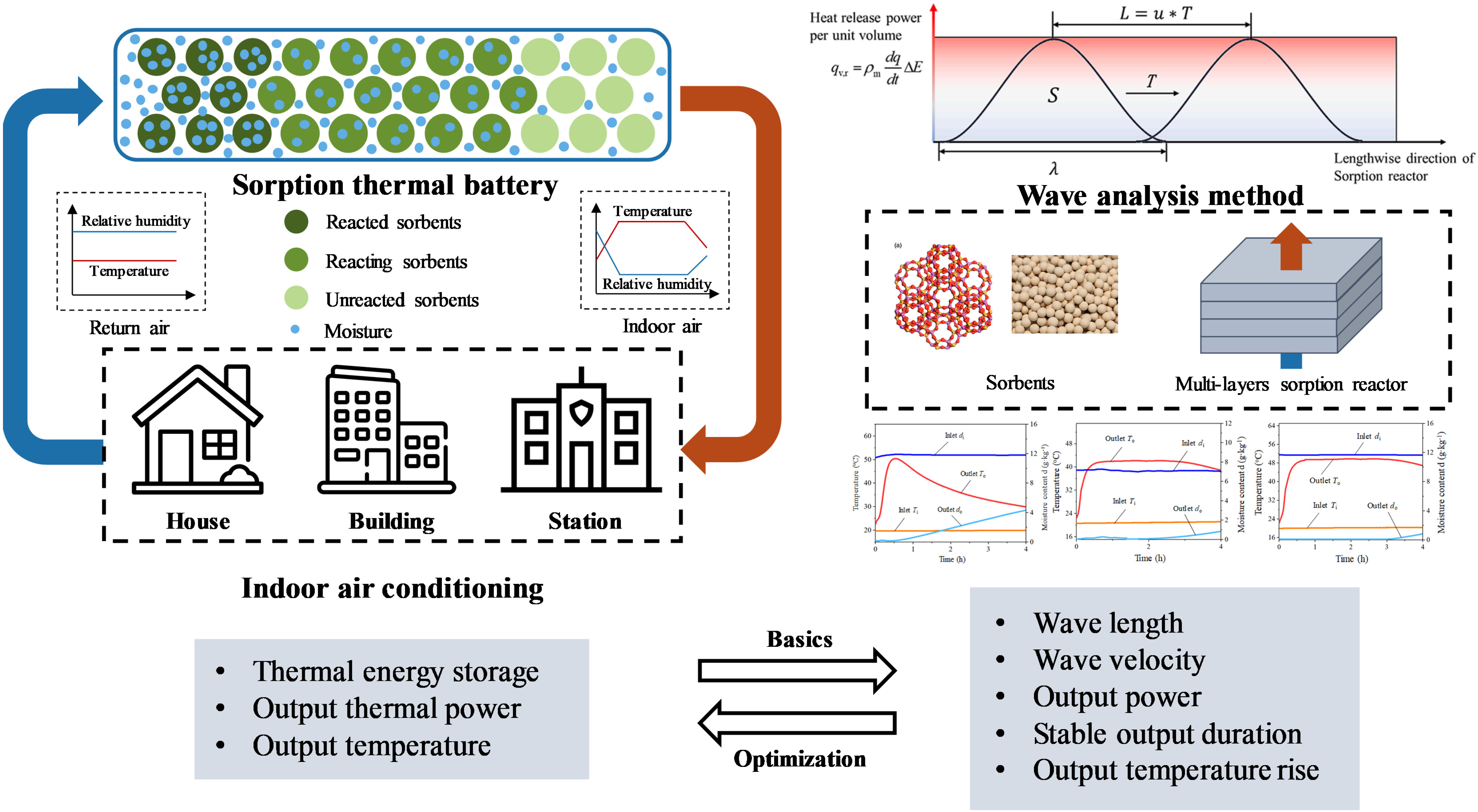
2.1. Wave Analysis Method

The water mass balance equation for a sorption reactor is described by Equation (1) when water loss is neglected.
v a ( d in d out ) ρ a = d q ( x ) d t ρ t d x
where the left side denotes the change in water amount in the air, and the right side is the sorbed water in the reactor.
The mass transfer rate of the sorption reaction is calculated by the linear driving force (LDF) equation as Equation (2).
d q d t = k ( q equ q )
Heat release power per unit volume is defined as wave height and expressed as Equation (3).
q v = ρ t d q d t Δ E
The wave equation of the sorption reaction can be described by combining Equations (1) and (2) and shown as Equation (4).
v a ( d in d out ) ρ a = L 1 L 2 k ( q equ ( x ) q ( x ) ) ρ t d x
where L1 and L2 are the start and end positions of the sorption reaction. For a complete reaction wave, qv is equal to zero at L1 and L2. In a reaction section with length L2L1, a sorption reaction occurs, and sorption heat is released.
Then, several wave parameters are defined as follows: During the reaction process, the wave moves from the inlet to the outlet of the reactor in a constant wave velocity, u. It is determined by obtaining the distance between two wave patterns with a time difference. The wave length λ is defined as the length where the sorption reaction occurs in the range of L2L1. Wave area S is obtained by integrating wave height with the whole reactor and is the sum of heat released by the whole sorption reactor per second. Output duration t is defined as the ratio of stable output length, Lbλ, to wave velocity.
According to the definition of sorption wave and the wave parameters, the most basic conditions for stable output of a sorption reactor are obtained: The length of the reactor should be longer than the wave length. When the wave length is too long, a complete wave pattern will not appear in the limited reactor. Thus, the output temperature will keep declining after increasing to the peak, and a stable output is not available. Due to the variety of wave patterns, it is difficult to characterize wave patterns accurately. The common characteristic for sorbents with type I and type V isotherms is a large and uniform slope near a particular relative humidity. When the reaction of a specific position achieves the highest reaction wave, the sorption reaction progresses to half of the entire reaction. In this condition, the water sorbed is approximately half of the equilibrium sorption capacity under the LDF assumption [44]. Thus, the wave patterns are simplified, and Equation (4) can be rewritten as Equation (5).
L = L 2 L 1 = 4 v a ( d in d out ) ρ a k q equ ( x ) ρ t
The value of L* represents the ability of sorbents to generate stable heat output. The larger the value of L*, the harder it is for sorbents to generate a stable output. Thus, it is important to choose the appropriate structure and operation parameters for the sorption reactor.

2.2. Analysis of Variance (ANOVA)

ANOVA can be utilized to obtain the influence degree of each parameter on sorption reaction and stable output ability. Based on the result of the wave analysis method, the influence parameters are chosen as length of sorption reactor, air velocity, sorption kinetic coefficient, reactor porosity, and inlet air relative humidity. The ANOVA is based on sets of orthogonal simulation results. The correlation of influence parameters on wave parameters is shown in Table 2.
Among the five influence parameters, reactor porosity and relative humidity have an impact on all wave parameters, and relative humidity has the most obvious influence on output power, stable output duration, and output temperature rise. Reactor length has a correlation with wave parameters except for wave velocity. And air velocity has a significant influence on stable output duration, and its effect on output temperature rise is ignored. In the optimization of the sorption reactor, the influence parameters should be easy to adjust and change. Thus, three parameters, i.e., sorption reactor length, air velocity, and inlet air relative humidity, are selected for further experiments.

2.3. Experimental Rig

To explore the practical heat release performance of STBs, an experimental rig is designed and established by using a real indoor air duct. A schematic diagram of the whole STB system is illustrated in Figure 2, in which Figure 2a indicates the STB and the auxiliary components, Figure 2b shows the photo of the experimental system, and Figure 2c is the design of the sorption reactor. The inner square of the reactor is 310 mm × 310 mm, and the outer rectangular base plate structure is 420 mm × 480 mm. The construction of the adsorption reactor is a layered design. The structure and physical map of each layer are also presented. It is indicated that the experimental rig could be divided into three parts, i.e., sorption reactor, air treatment before the reactor, and heat release part after the reactor. For the air treatment section, the main apparatus includes electric heaters, humidifiers, temperature and humidity sensors, etc. The electric heater and humidifier are used to control the temperature and humidity of inlet air for the sorption reactor. For the heat release section after the reactor, the main apparatus includes a temperature and humidity sensor, nozzle, pressure difference sensor, and fan. The internal air is extracted from the upper side of the system, thereby driving the airflow in the adsorption system. The fan is connected to the control cabinet, and the fan power can be manually changed to adjust the wind speed. The nozzle and the differential pressure sensor are used to measure air velocity. The pressure difference sensor is collected by Agilent 34970A data acquisition instrument (Agilent Technologies, Santa Clara, CA, USA). The temperature and humidity sensor in Table 3, i.e., VAISALA HTM100 (Vaisala, Vantaa, Finland), is used before and after the sorption reactor with the testing accuracy of ±1.5% RH and ±0.25 °C.
The experimental process of STB is illustrated as follows: (1) Initial set of STB system: The inlet air parameters of the sorption reactor, e.g., air velocity and humidity, are controlled through a control cabinet. (2) Pre-treatment of sorbents: Zeolite 13X is put into the drying oven and dried for 4–6 h at presetting temperatures of 250 °C. The purpose is to reduce the effect of moisture in the environment. (3) Set of sorption reactor: The dried zeolite 13X is put into the 3-layer sorption reactors, and potential air leaks are sealed. Then, the sorption reactors are arranged inside the air duct vertically. (4) Start of the experiment: Air flows through humidifiers and electric heaters, and the inlet air condition of the sorption reactor is controlled. Moisture is sorbed by sorbents filled in the reactor, and heat is released and carried by airflows. The relevant experimental parameters, such as inlet and outlet temperature and humidity, are recorded. Subsequently, the air flows to the top layer of the system, and the installed nozzle and differential pressure sensor are used to calculate and record air velocity. Then, the output heat of the STB system could be elevated by Equation (6), and total heat release can be defined by Equation (7). It is used to calculate the output power of the system, where the value of temperature difference is calculated according to the outlet and the inlet temperatures, which are used to calculate the total output of the system during the stable output stage; t1 and t2 are the stables.
Q = ρ a S v a C p , a Δ T
Q tot = t 1 t 2 Q ( t ) d t
where the value of temperature difference is calculated according to the temperatures of the outlet and the inlet equation (Equation (1)); t1 and t2 are the start and end moments of the stable output processes, respectively.
The moisture content could be converted by RH, as shown in Equation (8).
d = 622 φ P s P φ P s
where d is the moisture content of the air; Ps is the saturated water vapor partial pressure of the air; φ is RH of the air; and P is air pressure.

3. Results and Discussion

3.1. Pre-Experiment

In order to have a general understanding of the heat release performance of STBs, a pre-experiment is carried out to obtain the output parameters. Figure 3 indicates the heat release temperature and heat power of the STB under the condition of 80% RH, 20 °C working temperature, and 32 m3·h−1 inlet air volumetric flow. Also, a one-layer sorption reactor is first adopted with a length of 0.05 m. It indicates that the difference between the inlet and outlet moisture content represents the change in the adsorption rate and the greater the moisture content difference is, the larger the adsorption rate will become. During the pre-experiment, the moisture content difference decreases continuously, and the maximum value is 11.3 g·kg−1 at the beginning of the experiment. RH has been maintained at a level above 5% at the outlet of the adsorption reactor. The change in the moisture content difference decreases as the adsorption reaction proceeds.
The design of an open STB for heating must take the possible temperature change into consideration, which is directly affected by the change in the adsorption rate. High adsorption rate indicated by high moisture content difference leads to high release temperature. Corresponding to the moisture content difference, it is noted that there is a peak heat release temperature and output heat power during the whole heat release process. The highest output temperature rise could reach 31 °C, and the highest output heat power could reach 380 W at 20 min sorption time. It can be found that STBs using zeolite have a high heat release rate, which explains the high heat release power. However, the mass transfer rate of zeolite would decrease with the progression of time and eventually can no longer effectively adsorb the moisture in the air. Due to the low equilibrium adsorption capacity of the zeolite, the moisture in the air with high RH cannot be completely adsorbed by the zeolite, so the relative humidity of the outlet air in the whole process cannot be reduced below 5%.
The adsorbent inside the reactor is weighed after the experiment, and the average sorption capacity is calculated to be 0.29 g·kg−1. Figure 3c shows the change in total adsorption heat storage of the adsorption reactor. The changing trend of the total heat storage capacity of STBs is similar to that of the total water sorption capacity. The trend is steep up to 6 h and then flattens, which is because of the characteristics of the sorption reaction rate. Total adsorption heat storage capacity could reach 150 kWh·m−3. It can be inferred that the sorption reactor directly enters the final stage of the reaction process without the early stage and mediate stage. And the output power is unstable under pre-experiment conditions, which gives instruction for parameter analysis experiments.

3.2. Parameteric Analysis

According to the results of the pre-experiment, it could be found that under the condition of high moisture content, i.e., the value between the inlet and outlet of the adsorption reactor is equal to the theoretical maximum difference, the temperature rise of the reactor during the heat release process rises first and then declines. The adsorption behavior of the zeolite conforms to the assumption of the LDF adsorption equation. In order to extend the stable heat release time with constant temperature, the relevant parameters are varied in this section. The influence of the parameters on the stable output is investigated in terms of the length of the reactor, RH, and inlet air velocity.

3.2.1. Adsorption Reactor Length

First, various lengths of the adsorption reactor, i.e., 0.05 m, 0.10 m, and 0.15 m, are adopted to investigate the influence on heat release time for the stable output. Due to the limitation of the structure of the air duct, the largest length of the reactor is limited to 0.15 m. Figure 4 indicates output air temperature and moisture content in terms of various reactor lengths. The results show that with an increase in the reactor length, the outlet moisture content of the sorption reactor increases and gradually tends to be stable. The sorption reactor with a length of 0.05 m almost reaches the saturation state at the end of the experiment, as shown in Figure 4a. Comparably, the sorption reactor with a length of 0.15 m shows only half of the inlet air moisture content, as shown in Figure 4c. It Is obvious that the moist air residence time is improved with the length of the reactor and leads to an improved mass and heat transfer, which results better moisture removal rate. As a result, the highest heat release temperature tends to be stable with the increase in the length of the reactor. The stable heat output in this work is assumed when the temperature fluctuation is ±1 °C.
When the sorption reactor is 0.05 m, the stable heat release time only lasts 9.4 min. When the length is 0.1 m, the stable time lasts 34.2 min, as shown in Figure 4b. After further increasing the length of the reactor to 0.15 m, the total time of stable heat release could reach 80 min. It is demonstrated that the increased length of the adsorption reactor can effectively optimize the stable temperature output of the reactor. Figure 4d demonstrates the temperature rise and output power of the STB by using different adsorption reactor lengths. It indicates that the peak heat release temperature almost has no change with the increase in the length of the reactor so that the peak output power does not change at the same inlet airflow, which ranges from 365 to 385 W. This is mainly because the reactor length mainly determines the position of reaction front and the output power is decided by the internal working condition. Due to the increase in the stable heat release time, the total heat release increases for a longer length of the adsorption reactor. When the length of the reactor increases from 0.05 m to 0.15 m, total heat release ranges from 194.6 kJ to 1656.2 kJ.

3.2.2. Relative Humidity

According to the wave analysis method in our previous research, the RH value of the inlet air also has a great influence on stable heat release output. Based on the length of the adsorption reactor of 0.15 m, 50%, 60%, and 70% RH of the inlet air is adjusted to study the heat release performance with the same air velocity. Figure 5a–c indicate output air temperature and moisture content in terms of various RHs. It demonstrates that moisture content is close to zero during the stable heat release time. As the heat release process proceeds, the output temperature begins to decrease, and the moisture content of the outlet air gradually increases. Also, the rising trend of moisture content is accelerated with the increase in RH of the inlet air. The results show that the stable heat release time can be increased by reducing the RH of the inlet air. The stable heat release times are 106 min, 129 min, and 152 min when the RHs are 70%, 60%, and 50%, respectively. When the RH decreases from 70% to 50%, the stable heat release time increases to 1.9 times that of the results in the pre-experiment.
Figure 5d demonstrates the temperature rise and output power of the STB under the conditions of different RHs. High RH of inlet air is essential to enlarge the heat release temperature and output power but also poses more challenges, maintaining high temperature rise for a longer period with decreasing sorption capacity of the zeolite, as explained in Section 3.1. Although reducing RHs of inlet air reduces the heat release temperature and output power, the total heat release is increased due to the longer stable heat release time. When RHs decrease from 80% to 50%, the total heat amount increases from 1974.6 kJ to 2307.6 kJ. The reduction in inlet air relative humidity is beneficial for the improvement of stable output duration or make the sorption process appear early stage and mediate stage. The peak of output power decreases with the decrease in inlet air relative humidity, but the total heat output in the stable heat release section will increase accordingly.

3.2.3. Working Time

In order to investigate the influence of air velocity, comparative experiments are carried out under the air volume conditions of 16 m3·h−1, 24 m3·h−1, and 40 m3·h−1 when the length of the adsorption reactor is maintained at 0.15 m, and RH keeps as 50%. Figure 6a–c indicate output air temperature and moisture content with various inlet air velocities. For different air velocities, the output parameters are influenced by two-fold contrasting phenomena: (1) higher air velocity limits the air residence time in the reactor, which negatively affects the sorption performance; (2) the mass transfer barrier is reduced, and the adsorption kinetics are accelerated with increased air velocity which benefits the sorption performance. As shown in the figure, the outlet moisture content rises faster when the air velocity increases, which may be explained by the first phenomenon. Under the considered range, the inlet air velocity does not have much influence on the heat release temperature.
When air velocity increases from 16 m3·h−1 to 40 m3·h−1, the stable heat release time reduces from 182 min to 61 min, respectively. In comparison with the pre-experiment results, the heat release time increases by 2.3 times when the air velocity is reduced by 50%. Figure 6d demonstrates the temperature rise and output power of the STB using different inlet air velocities. The peak heat release power significantly decreases when air velocity decreases. Thus, the heat consumption of the end users determines the inlet air velocity, which means that stable heat release time can be adjusted within a certain range by reducing the air volume. Compared with adjusting the length of the reactor and inlet RHs, reducing air velocity should better not be selected as the first choice due to the reduced output power and the limited adjustment range. Also, because of the improvement of stable release time, the total heat release amount increases with the decrease in air velocity, which leads to a small output temperature fluctuation. When inlet air velocity decreases from 40 m3·h−1 to 16 m3·h−1, the total heat release amount ranges from 1578.5 kJ to 1955.7 kJ.

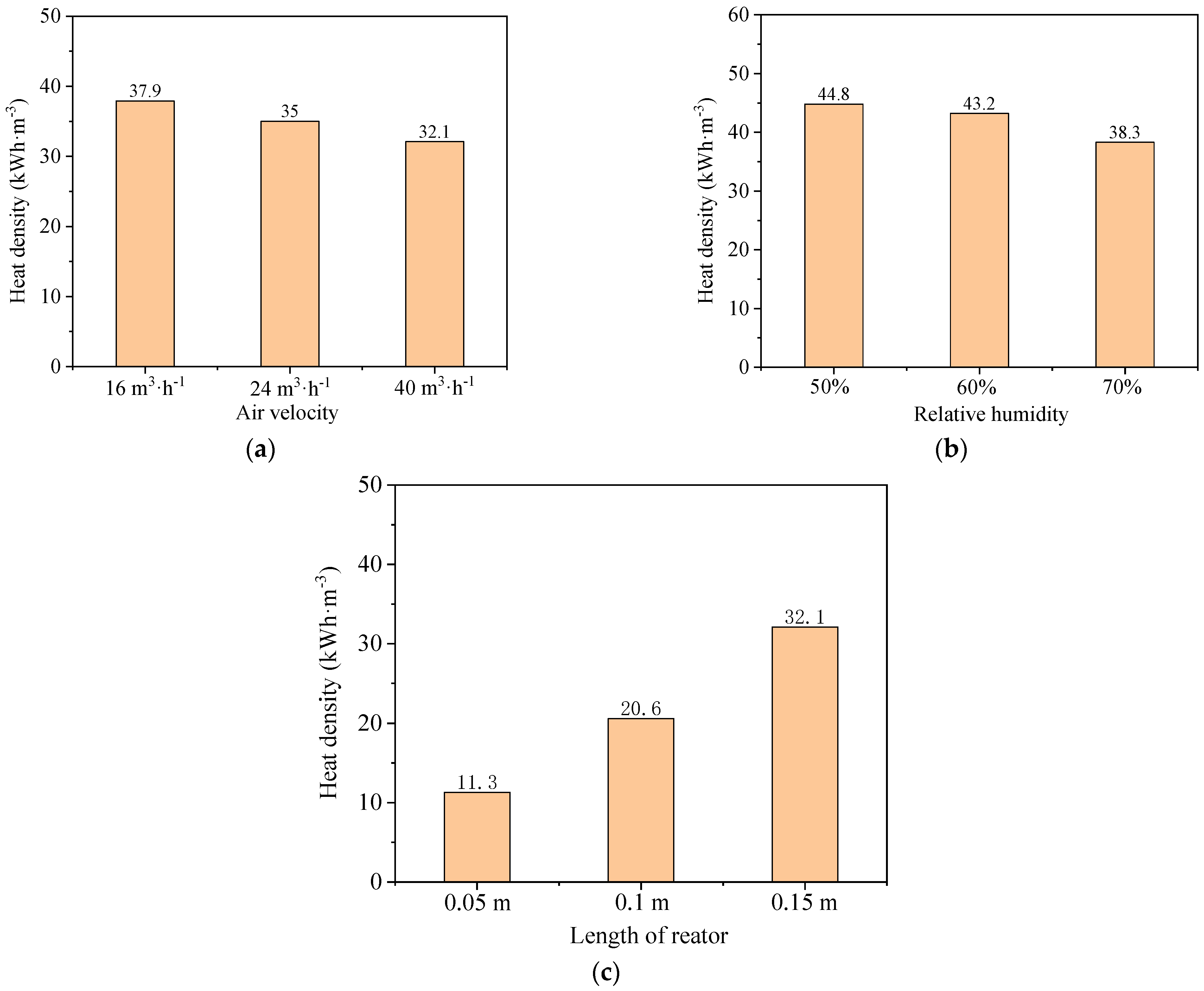
3.3. Comparison of Heat Release Performance among Various Parameters

In order to have a general understanding of the stable heat release performance of STBs by adjusting various parameters, the change in independent variable parameters is simplified by the normalization method, as shown in Figure 7. For the same comparative group, the longest stable heat release time in each group of experiments is used as the standard to calculate the ratio of each group under different working conditions. Parameter 0 corresponds to the parameter condition of the minimum heat release time, and parameter 1 corresponds to the parameter condition of the largest release time.
Some results could be found as follows:
(1)
Under the experimental conditions, the length of the reactor is conducive to stable heat release time, while the contribution of relative humidity and air volume to stable heat release time is negatively correlated. This experimental result is similar to that using the wave analysis method.
(2)
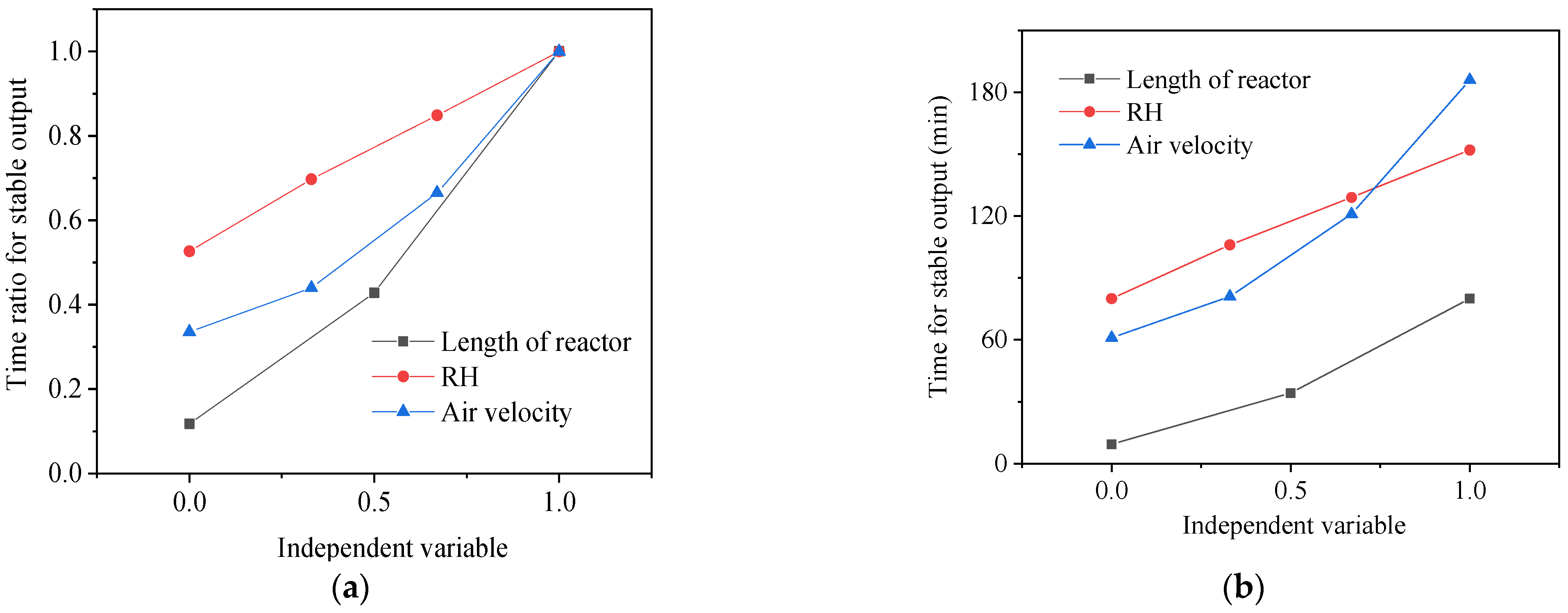
In each experiment, the variation in RH is 10%, and the change in air volume is 8 m3·h−1. The variation in the reactor length is 0.05 m. Each parameter can have a different influence on stable heat release time. The relative increase ratio of three independent variable parameters to the stable heat release time of the STB is then compared, as shown in Figure 7a. It indicates that the variation in reactor length has the most positive effect on stable heat release time. The increase in the ratio is 0.9 of the maximum stable heat release time. Secondly, the variation in air velocity can also significantly change the stable heat release time. The increase ratio between various groups of air velocity is 0.66 of the maximum stable heat release time. Comparably, RH has the lowest increase ratio, and its stable heat release time has an increase ratio of 0.53.
(3)
Between each group of experiments, a difference in the response degree of the stable heat release time to each parameter is indicated in Figure 7b. The stable heat release time is increased to about 80 min by increasing the length of the reactor. When reducing air velocity and inlet RH, the stable heat release time could be increased to 182 min and 152 min, respectively. From this perspective, increasing the length of the adsorption reactor and reducing inlet air velocity are more effective in extending the stable heat release time than reducing the RH of the inlet air.
Based on the experimental results, Figure 8 indicates the total heat release amount in terms of the specific volume adsorber. When the above parameters are adjusted, the stable heat release amount of the specific volume of the reactor ranges between 40.7 MJ and 161.1 MJ. For the comparison among different lengths of the reactor, the heat release of the specific volume of the reactor increases from 40.7 MJ to 115.6 MJ. Since the volume of the reactor has not changed, the range of heat release at constant temperature is only related to the total amount of heat release. It can be found that its change law follows the same change law as the total amount of heat released. At low RH, its maximum specific stable heat release could reach 161.1 MJ. Under the condition of low wind speed, the maximum specific stable heat release reaches 136.5 MJ. Moreover, the length of the reactor is greatly conducive to heat storage efficiency. Although air velocity significantly increases stable heat release time, the increase in the total heat storage amount is lower than that in reducing RH due to the reduction in heat release power.
Therefore, three optimization methods are evaluated by comprehensively analyzing heat release time and heat storage efficiency. It demonstrates that increasing the length of the adsorption reactor is the first choice for the optimization of STB system control. Its advantage is that it can achieve stable temperature without affecting heat release power. The extension of heat release time can also increase the stable heat release amount per unit volume of adsorber and improve heat storage efficiency. In addition, adjusting the RH of the inlet air of the reactor is an effective method. Although reducing RH has an influence on heat release power, it can bring about a large increase in stable heat release time and heat storage per unit volume. Finally, regulating the air velocity of the system has limited improvement for the optimization of the STB. Although this method could increase stable heat release time, the increase in the total amount of heat storage is not obvious.

4. Conclusions

To explore the real heat release performance of STBs based on wave analysis methods, an experimental investigation of STBs is conducted in this paper. The relative humidity of inlet gas, system air velocity, and the length of the reactor are considered the key parameters to optimize the experimental performance of the open STB. Some conclusions could be yielded as follows:
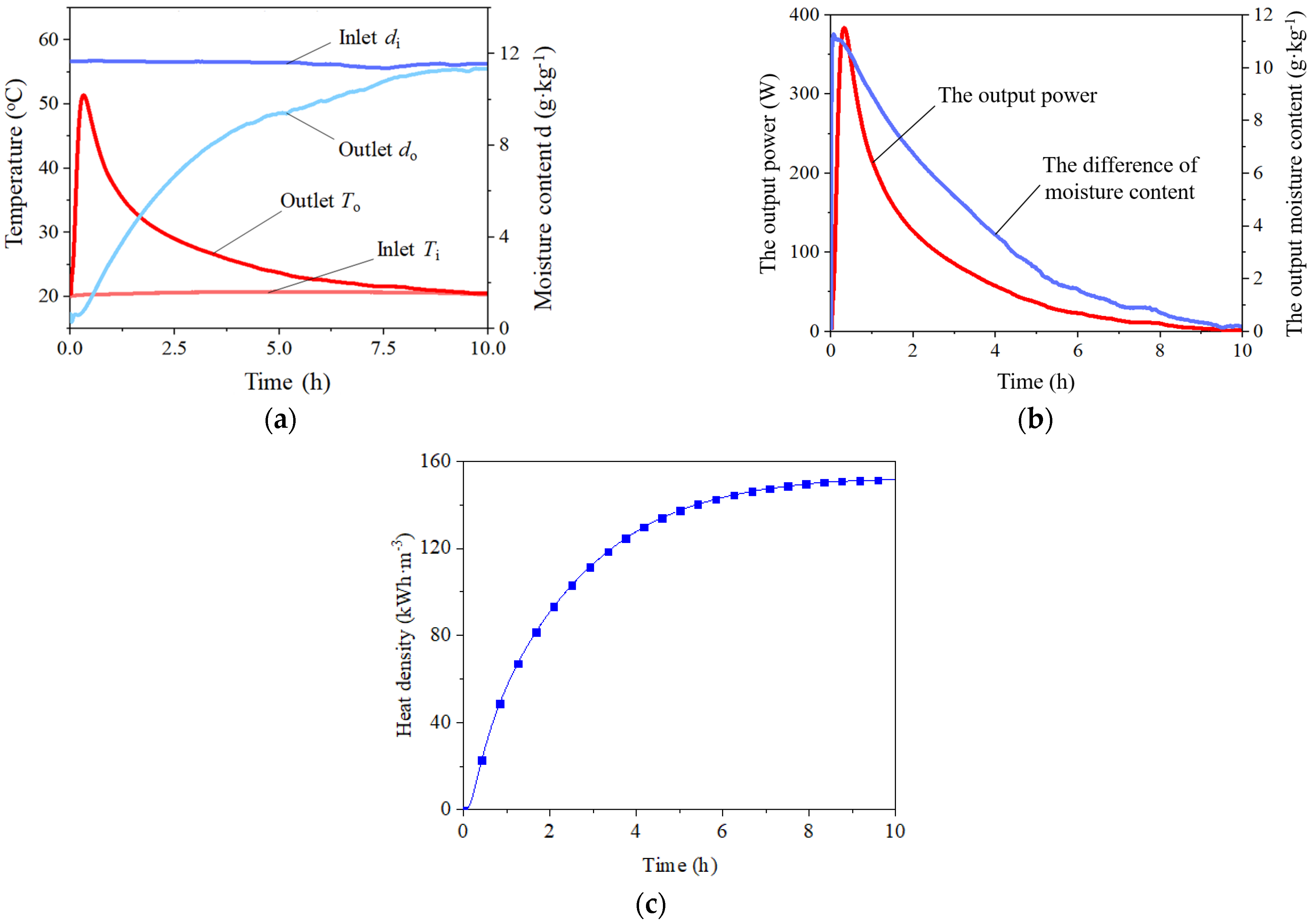
  • For the typical STB experiment, there would be a peak in the heat release process. The highest heat release temperature could reach 31 °C when the sorption time is 20 min. STBs using zeolite cannot completely absorb the moisture in the air, so the relative humidity of the outlet air in the whole process cannot be reduced below 5%. The adsorbents inside the reactor are weighed after the experiment, and the average sorption capacity is calculated to be 0.29 g·kg−1. The changing trend of the total heat storage capacity of STBs is similar to that of the total water sorption capacity. Total adsorption heat storage capacity could reach 150 kWh·m−3.
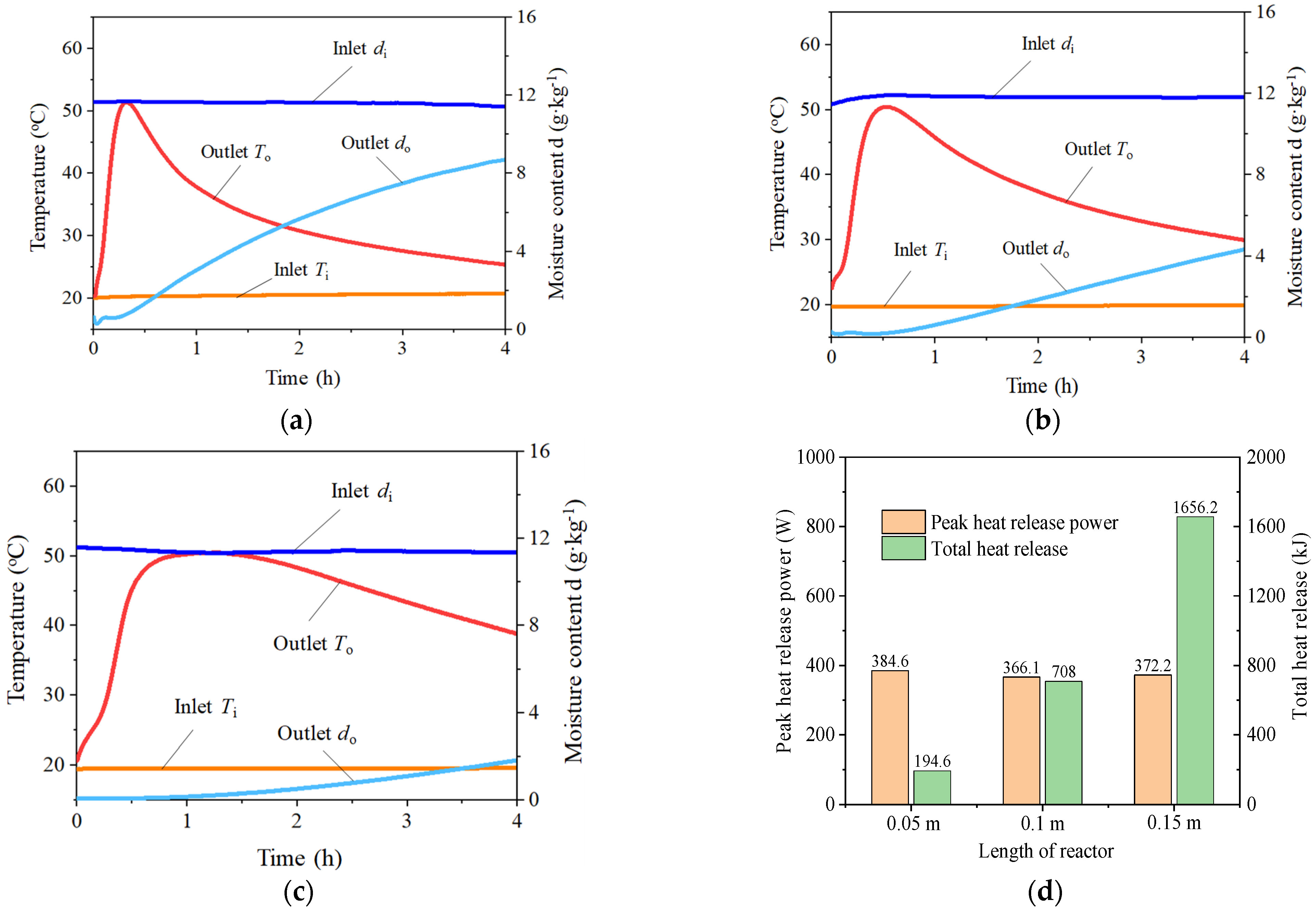
  • For different reactor lengths, the outlet moisture content of the sorption reactor increases and stabilizes as the length of the sorption reactor increases from 0.05 m to 0.15 m, resulting in increased stable heat release time (from 9.4 min to 80 min) and total heat release (from 194.6 kJ to 1656.2 kJ). Varying the relative humidity (RH) impacts the stable heat release time, with reductions in RH leading to longer duration: 106 min at 70% RH, 129 min at 60% RH, and 152 min at 50% RH. When RHs decrease from 80% to 50%, the total heat amount increases from 1974.6 kJ to 2307.6 kJ due to the longer stable heat release time. By increasing inlet air velocity, the outlet moisture content rises faster, where an increase in air velocity from 16 m3·h−1 to 40 m3·h−1 reduces the stable heat release time from 182 min to 61 min. In comparison with the pre-experiment results, the heat release time increases by 2.3 times when the air velocity is reduced by 50%. Accordingly, the total heat release amount ranges from 1578.5 kJ to 1955.7 kJ.
  • The heat release time and heat storage efficiency are optimized in terms of reactor length, RH, and air velocity. Increasing the length of the adsorption reactor is the first choice for the optimization of STB system control. It can achieve stable temperature without affecting heat release power. Also, heat release time should be extended to increase the stable heat release amount per unit volume of adsorber and improve heat storage efficiency. Adjusting the RH of the inlet air for STBs is an effective method. Although reducing RH has an influence on heat release power, it can bring about a large increase in stable heat release time and heat storage per unit volume. However, air velocity regulation of the STB system has limited improvement for the system optimization. Although this method could increase stable heat release time, the increase in the total amount of heat storage is not obvious.

Author Contributions

Conceptualization, M.Y. and L.J.; methodology, W.L.; software, Y.L.; formal analysis, M.Y.; resources, X.Z.; data curation, L.J.; writing—original draft preparation, M.Y.; writing—review and editing, L.J. and N.G. All authors have read and agreed to the published version of the manuscript.

Funding

This research was supported by the National Natural Science Foundation of China (No. 52276022), Key Research and Development Project of Jiangsu Province (BE2022001-5), Science and Technology Project of State Administration for Market Regulation (2023MK041), Science and Technology Project of Special Equipment Safety Supervision and Inspection Institute of Jiangsu Province (KJ(Y)202415), Jiangsu Provincial Double-Innovation Doctor Program (JSSCBS20230188), and the Basic Research Funds for the Central Government ‘Innovative Team of Zhejiang University’ under contract number (2-2050205-22-68).

Institutional Review Board Statement

Not applicable.

Informed Consent Statement

Not applicable.

Data Availability Statement

The data presented in this study are available on request from the corresponding author.

Conflicts of Interest

The authors declare no conflicts of interest.

Nomenclature

Greek symbols
ANOVAAnalysis of variance
COPCoefficient of performance
CpSpecific heat, J·kg·K−1
dMoisture content of the air, g·kg−1
ESDEnergy storage density
kKinetic coefficient, s−1
L*Stable output parameter
L1, L2Start and end position of sorption reaction, m
LbSorption reactor length, m
LDFLinear driving force
LHSLatent heat storage
PAir pressure, Pa
PsSaturated water vapor partial pressure of the air, Pa
PPPolypropylene
PCMPhase change material
qSorption capacity, g·kg−1
qequEquilibrium orbed capacity, g·kg−1
qvHeat release power per unit volume, W·m−3
QOutput power, W
QtotTotal heat output, J
RHRelative humidity
sArea, m2
SWave area, W
SHSSensible heat storage
STBSorption thermal battery
STESSorption thermal energy storage
tStable output duration, s
t1, t2Start and end time of stable output stage, s
TESThermal energy storage
THSThermochemical heat storage
uWave velocity, m·s−1
vVelocity, m·s−1
Other symbols
ρDensity, kg·m−3
λWave length, m
φRelative humidity of the air
εReactor porosity
ΔTTemperature difference, °C
ΔESorption heat, J·kg−1
Subscripts
aAir
tSorbent
inInlet of the reactor
outOutlet of the reactor

References

  1. Zhang, Z.; Zhang, J.; Yuan, H.; Zheng, X.; Mei, N. Design and experimental analysis of energy-saving and heat storage of a hot water tank based on the source-sink matching principle. Case Stud. Therm. Eng. 2023, 41, 102672. [Google Scholar] [CrossRef]
  2. Jiang, L.; Xie, R.Y.; Shi, W.K.; Wu, E.Y.; Li, B.; Zhang, X.J. Water effect on adsorption carbon capture in metal-organic framework: A molecular simulation. Carbon Capture Sci. Technol. 2022, 4, 100061. [Google Scholar] [CrossRef]
  3. Aslannezhad, M.; Ali, M.; Kalantariasl, A.; Sayyafzadeh, M.; You, Z.; Iglauer, S.; Keshavarz, A. A review of hydrogen/rock/brine interaction: Implications for Hydrogen Geo-storage. Prog. Energy Combust. Sci. 2023, 95, 101066. [Google Scholar] [CrossRef]
  4. Vecchi, A.; Sciacovelli, A. Long-duration thermo-mechanical energy storage—Present and future techno-economic competitiveness. Appl. Energy 2023, 334, 120628. [Google Scholar] [CrossRef]
  5. Mahmoud, M.; Ramadan, M.; Olabi, A.-G.; Pullen, K.; Naher, S. A review of mechanical energy storage systems combined with wind and solar applications. Energy Convers. Manag. 2020, 210, 112670. [Google Scholar] [CrossRef]
  6. Steinmann, W.-D. Thermo-mechanical concepts for bulk energy storage. Renew. Sustain. Energy Rev. 2017, 75, 205–219. [Google Scholar] [CrossRef]
  7. Tan, S.; Zhang, X. Progress of research on phase change energy storage materials in their thermal conductivity. J. Energy Storage 2023, 61, 106772. [Google Scholar] [CrossRef]
  8. Hua, W.; Lv, X.; Zhang, X.; Ji, Z.; Zhu, J. Research progress of seasonal thermal energy storage technology based on supercooled phase change materials. J. Energy Storage 2023, 67, 107378. [Google Scholar] [CrossRef]
  9. Olabi, A.G.; Abdelghafar, A.A.; Maghrabie, H.M.; Sayed, E.T.; Rezk, H.; Radi, M.A.; Obaideen, K.; Abdelkareem, M.A. Application of artificial intelligence for prediction, optimization, and control of thermal energy storage systems. Therm. Sci. Eng. Prog. 2023, 39, 101730. [Google Scholar] [CrossRef]
  10. Lyden, A.; Brown, C.S.; Kolo, I.; Falcone, G.; Friedrich, D. Seasonal thermal energy storage in smart energy systems: District-level applications and modelling approaches. Renew. Sustain. Energy Rev. 2022, 167, 112760. [Google Scholar] [CrossRef]
  11. Tawalbeh, M.; Khan, H.A.; Al-Othman, A.; Almomani, F.; Ajith, S. A comprehensive review on the recent advances in materials for thermal energy storage applications. Int. J. Thermofluids 2023, 18, 100326. [Google Scholar] [CrossRef]
  12. Mahon, H.; O’Connor, D.; Friedrich, D.; Hughes, B. A review of thermal energy storage technologies for seasonal loops. Energy 2022, 239, 122207. [Google Scholar] [CrossRef]
  13. Lingayat, A.; Das, P.; Gilago, M.C.; Chandramohan, V.P. A detailed assessment of paraffin waxed thermal energy storage medium for solar dryers. Sol. Energy 2023, 261, 14–27. [Google Scholar] [CrossRef]
  14. Crespo, A.; Fernández, C.; Vérez, D.; Tarragona, J.; Borri, E.; Frazzica, A.; Cabeza, L.F.; de Gracia, A. Thermal performance assessment and control optimization of a solar-driven seasonal sorption storage system for residential application. Energy 2023, 263, 125382. [Google Scholar] [CrossRef]
  15. Ding, Z.; Wu, W. A novel double-effect compression-assisted absorption thermal battery with high storage performance for thermal energy storage. Renew. Energy 2022, 191, 902–918. [Google Scholar] [CrossRef]
  16. Wang, T.; Zhao, C.Y.; Yan, J. Investigation on the Ca(OH)2/CaO thermochemical energy storage system with potassium nitrate addition. Sol. Energy Mater. Sol. Cells 2020, 215, 110646. [Google Scholar] [CrossRef]
  17. Wang, K.W.; Yan, T.; Pan, W.G. Optimization strategies of microencapsulated phase change materials for thermal energy storage. J. Energy Storage 2023, 68, 107844. [Google Scholar] [CrossRef]
  18. Yan, J.; Pan, Z.H.; Zhao, C.Y. Experimental study of MgO/Mg(OH)2 thermochemical heat storage with direct heat transfer mode. Appl. Energy 2020, 275, 115356. [Google Scholar] [CrossRef]
  19. Humphries, T.D.; Paskevicius, M.; Alamri, A.; Buckley, C.E. Thermodynamic destablization of SrH2 using Al for the next generation of high temperature thermal batteries. J. Alloys Compd. 2022, 894, 162404. [Google Scholar] [CrossRef]
  20. Li, S.; Yang, X.; Li, X.; Qu, W.; Zhou, T.; Dong, T.; Deng, L.; Zhang, J.; Zhao, J. A high energy density 3D nano-carbon based magnesium hydroxide reversible chemical reaction heat storage material synthesis and heat transfer performance investigation. J. Energy Storage 2022, 50, 104260. [Google Scholar] [CrossRef]
  21. Zeng, Z.; Zhao, B.; Wang, R. Water based adsorption thermal battery: Sorption mechanisms and applications. Energy Storage Mater. 2023, 54, 794–821. [Google Scholar] [CrossRef]
  22. Ding, Z.; Wu, W. Type II absorption thermal battery for temperature upgrading: Energy storage heat transformer. Appl. Energy 2022, 324, 119748. [Google Scholar] [CrossRef]
  23. Girnik, I.S.; Grekova, A.D.; Li, T.X.; Wang, R.Z.; Dutta, P.; Murthy, S.S.; Aristov, Y.I. Composite “LiCl/MWCNT/PVA” for adsorption thermal battery: Dynamics of methanol sorption. Renew. Sustain. Energy Rev. 2020, 123, 109748. [Google Scholar] [CrossRef]
  24. Jiang, L.; Wang, L.; Wang, R.; Zhu, F.; Lu, Y.; Roskilly, A.P. Experimental investigation on an innovative resorption system for energy storage and upgrade. Energy Convers. Manag. 2017, 138, 651–658. [Google Scholar] [CrossRef]
  25. Jiang, L.; Roskilly, A.P.; Wang, R.Z.; Wang, L.W. Analysis on innovative resorption cycle for power and refrigeration cogeneration. Appl. Energy 2018, 218, 10–21. [Google Scholar] [CrossRef]
  26. Jiang, L.; Liu, W.; Lin, Y.C.; Wang, R.Q.; Zhang, X.J.; Hu, M.K. Hybrid thermochemical sorption seasonal storage for ultra-low temperature solar energy utilization. Energy 2022, 239, 122068. [Google Scholar] [CrossRef]
  27. Sharma, R.; Anil Kumar, E.; Dutta, P.; Srinivasa Murthy, S.; Aristov, Y.I.; Tokrev, M.M.; Li, T.; Wang, R. Ammoniated salt based solid sorption thermal batteries: A comparative study. Appl. Therm. Eng. 2021, 191, 116875. [Google Scholar] [CrossRef]
  28. Chao, J.; Xu, J.; Bai, Z.; Wang, P.; Wang, R.; Li, T. Integrated heat and cold storage enabled by high-energy-density sorption thermal battery based on zeolite/MgCl2 composite sorbent. J. Energy Storage 2023, 64, 107155. [Google Scholar] [CrossRef]
  29. ElBahloul, A.A.; Zeidan, E.-S.B.; El-Sharkawy, I.I.; Hamed, A.M.; Radwan, A. Recent advances in multistage sorption thermal energy storage systems. J. Energy Storage 2022, 45, 103683. [Google Scholar] [CrossRef]
  30. Wu, S.-F.; Wang, L.-W.; An, G.-L.; Zhang, B. Excellent ammonia sorption enabled by metal-organic framework nanocomposites for seasonal thermal battery. Energy Storage Mater. 2023, 54, 822–835. [Google Scholar] [CrossRef]
  31. Gkaniatsou, E.; Meng, B.; Cui, F.; Loonen, R.; Nouar, F.; Serre, C.; Hensen, J. Moisture-participating MOF thermal battery for heat reallocation between indoor environment and building-integrated photovoltaics. Nano Energy 2021, 87, 106224. [Google Scholar] [CrossRef]
  32. Mileo, P.G.M.; Ho Cho, K.; Park, J.; Devautour-Vinot, S.; Chang, J.-S.; Maurin, G. Unraveling the Water Adsorption Mechanism in the Mesoporous MIL-100(Fe) Metal–Organic Framework. J. Phys. Chem. C 2019, 123, 23014–23025. [Google Scholar] [CrossRef]
  33. Yan, T.; Li, T.; Xu, J.; Chao, J.; Wang, R.; Aristov, Y.I.; Gordeeva, L.G.; Dutta, P.; Murthy, S.S. Ultrahigh-Energy-Density Sorption Thermal Battery Enabled by Graphene Aerogel-Based Composite Sorbents for Thermal Energy Harvesting from Air. ACS Energy Lett. 2021, 6, 1795–1802. [Google Scholar] [CrossRef]
  34. Strelova, S.V.; Gordeeva, L.G.; Grekova, A.D.; Salanov, A.N.; Aristov, Y.I. Composites “lithium chloride/vermiculite” for adsorption thermal batteries: Giant acceleration of sorption dynamics. Energy 2023, 263, 125733. [Google Scholar] [CrossRef]
  35. Li, W.; Jaromír Klemeš, J.; Wang, Q.; Zeng, M. Efficient thermal management strategy of Li-ion battery pack based on sorption heat storage. Energy Convers. Manag. 2022, 256, 115383. [Google Scholar] [CrossRef]
  36. Li, W.; Klemeš, J.J.; Wang, Q.; Zeng, M. Salt hydrate–based gas-solid thermochemical energy storage: Current progress, challenges, and perspectives. Renew. Sustain. Energy Rev. 2022, 154, 111846. [Google Scholar] [CrossRef]
  37. Aydin, D.; Casey, S.P.; Chen, X.; Riffat, S. Novel “open-sorption pipe” reactor for solar thermal energy storage. Energy Convers. Manag. 2016, 121, 321–334. [Google Scholar] [CrossRef]
  38. Malley-Ernewein, A.; Lorente, S. Analysis of thermochemical energy storage in an elemental configuration. Sci. Rep. 2019, 9, 15875. [Google Scholar] [CrossRef]
  39. Michel, B.; Mazet, N.; Neveu, P. Experimental investigation of an open thermochemical process operating with a hydrate salt for thermal storage of solar energy: Local reactive bed evolution. Appl. Energy 2016, 180, 234–244. [Google Scholar] [CrossRef]
  40. Hanikel, N.; Prévot, M.S.; Fathieh, F.; Kapustin, E.A.; Lyu, H.; Wang, H.; Diercks, N.J.; Glover, T.G.; Yaghi, O.M. Rapid Cycling and Exceptional Yield in a Metal-Organic Framework Water Harvester. ACS Cent. Sci. 2019, 5, 1699–1706. [Google Scholar] [CrossRef]
  41. Fisher, R.; Ding, Y.; Sciacovelli, A. Hydration kinetics of K2CO3, MgCl2 and vermiculite-based composites in view of low-temperature thermochemical energy storage. J. Energy Storage 2021, 38, 102561. [Google Scholar] [CrossRef]
  42. Zhang, Y.; Dong, H.; Wang, R.; Feng, P. Air humidity assisted sorption thermal battery governed by reaction wave model. Energy Storage Mater. 2020, 27, 9–16. [Google Scholar] [CrossRef]
  43. Zhang, Y.; Wang, R. Sorption thermal energy storage: Concept, process, applications and perspectives. Energy Storage Mater. 2020, 27, 352–369. [Google Scholar] [CrossRef]
  44. Lin, Y.C.; Fan, Y.B.; Chen, S.; Zhang, X.J.; Frazzica, A.; Jiang, L. Wave analysis method for air humidity assisted sorption thermal battery: A new perspective. Energy Convers. Manag. 2023, 277, 116638. [Google Scholar] [CrossRef]
Figure 1. The general concept of wave analysis method for the open STB: (a) molecular structure of sorbents.
Sustainability 16 06654 g001
Figure 2. The whole STB system: (a) system schematic, (b) photo of the main components, and (c) sorption reactor design.
Sustainability 16 06654 g002
Figure 3. Heat release performance of STB: (a) air condition, (b) output power, and (c) heat density.
Sustainability 16 06654 g003
Figure 4. The heat release performance of STB vs. various lengths of the sorption reactor: (a) 0.05 m, (b) 0.1 m, (c) and 0.15 m. (d) Heat output.
Sustainability 16 06654 g004
Figure 5. The heat release performance of STB vs. various RHs: (a) 50%, (b) 60%, (c) 70%, and (d) heat release of the STB under the conditions of different RHs.
Sustainability 16 06654 g005
Figure 6. The heat release performance of STB vs. various air velocities: (a) 16 m−3·h−1; (b) 24 m−3·h−1; (c) 40 m−3·h−1; and (d) heat release of the STB under the conditions of different air velocities.
Sustainability 16 06654 g006
Figure 7. Comparison of the stable heat release time: (a) time ratio and (b) time.
Sustainability 16 06654 g007
Figure 8. The stable heat release per unit volume by (a) air velocity, (b) RH, and (c) length of the reactor.
Sustainability 16 06654 g008
Table 1. Current status of various TES technologies [9,10,11].
MethodSensibleLatentChemical
Energy densitySmall (0.2 GJ·m−3)Medium (0.3–0.5 GJ·m−3)Large (0.7–3.0 GJ·m−3)
MediumWater, pebble, soil, etc.Organics, inorganicsMetal chlorides, metal hydrides
LifespanLongLimited by PCMLimited by reactants
AdvantagesLow cost, simple, reliable, environmentally friendlyHigher energy density, constant temperatureHighest energy density, negligible heat loss
DisadvantagesLarge heat loss, high cost of constructionCrystallization, corrosionComplex system, high initial investment
State of developmentLarge-scale demonstration plantsLab-scale prototypes, several commercial productsLab-scale prototypes
Table 2. The correlation table between influence parameters and wave parameters.
Influence ParametersWave Parameters
Wave Length, LWave Velocity, vOutput Power, SStable Output Duration, tOutput Temperature Rise, ΔT
Sorption reactor length, Lb×
Air velocity, va×
Kinetic coefficient, k××××
Reactor porosity, ε
Air relative humidity, RH
×: no correlation, √: correlation (0.05 > p > 0.01), and ○: significant correlation (0.01 > p).
Table 3. Testing apparatus and types with measurement accuracy.
Testing Apparatus/TypeMeasurement Accuracy
Temperature and humidity sensors
VAISALA HTM100
±1.5% RH
±0.25 °C
Agilent 349370A22-bit resolution
Pressure transducers±1.0%
Disclaimer/Publisher’s Note: The statements, opinions and data contained in all publications are solely those of the individual author(s) and contributor(s) and not of MDPI and/or the editor(s). MDPI and/or the editor(s) disclaim responsibility for any injury to people or property resulting from any ideas, methods, instructions or products referred to in the content.

