Article

Numerical Simulation Study on Vibration Characteristics and Influencing Factors of Coal Containing Geological Structure

1
College of Safety Science and Engineering, Xi’an University of Science and Technology, Xi’an 710054, China
2
Research Center for Intelligent Gas Extraction Engineering in Western Mines, Xi’an 710054, China
*
Author to whom correspondence should be addressed.
Sustainability 2024, 16(17), 7390; https://doi.org/10.3390/su16177390
Submission received: 12 July 2024 / Revised: 10 August 2024 / Accepted: 23 August 2024 / Published: 27 August 2024

Abstract

:
Accurately determining the natural frequency of coal-containing geological structures is crucial for preventing mine dynamic disasters and utilizing vibration waves to break coal and enhance its permeability. Based on the modal theory of rock, vibration models of coal-containing geological structures, including layering and fractures are established. By analysis, the undamped vibration equation and its characteristic equation for both the layered coal system and the fractured coal system are derived. Subsequently, the Lanczos method is employed to solve the system’s vibration modes using ABAQUS. The effects of the layering position, layering thickness, layering physical properties, crack width, and crack length on the natural frequency and vibration response of coal-containing geological structures are investigated. The results indicate that when a single influencing factor is altered, the displacement response distribution of the coal body vibration system with geological structures remains essentially the same, and these single influencing factors have a minimal impact on the vibration displacement of the coal-containing geological structure. The natural frequency of the system decreases exponentially as the distance between the layering and the geometric center of the coal system with geological structures increases. The presence of layering in the coal system with geological structures significantly reduces the system’s natural frequency. The natural frequency of the coal system with geological structures increases in a power function manner as the layering elastic modulus increases. Conversely, the natural frequency decreases with an increase in crack length. When the change ranges of crack width and bedding thickness are the same, the natural frequency of the fractured coal body system exhibits more significant changes. The natural frequency of the coal system with geological structures initially decreases and then increases as bedding thickness and crack width increase. The trend in the natural frequency changes and the position of the extreme point are related to the ratio of the elastic modulus and density of the geological structure.

1. Introduction

Vibration is a common physical phenomenon, which widely exists in coal mining. On the one hand, the vibration effect in mining activities can induce dynamic disasters such as rock bursts [1] and coal and gas outbursts [2]; on the other hand, vibration can be used to break the coal body, increase the fracture of the coal body, and improve the permeability of the coal body [3], such as ultrasonic high-frequency vibration rock fracturing technology [4].
The influence of vibration on the outside world depends not only on the energy and form of the vibration source but also on the parameters such as the natural frequency of the coal body. The research shows that when the frequency of the vibration source and the natural frequency of the coal body are within a certain range, it will become a necessary condition for inducing coal and gas outbursts and other coal and rock dynamic disasters [5]. In addition, the practice of vibration wave breaking coal body and increasing coal body permeability shows that when the frequency of vibration wave is close to the natural frequency of the coal body, the effect of coal body breaking and increasing permeability is the best [6]. Bibinur S. Akhymbayeva et al. [7] employed the percussion method to test the natural frequency of artificial cores made of quartz sand and aluminum sulfate, confirming that the crack propagation speed in the rock is fastest when the vibration frequency of the drill bit approaches the rock’s natural frequency. Zhihui Wen et al. [8] considered the three main control parameters, i.e., excitation force, coal sample size, and mechanical parameters, and the response characteristics of coal vibration excited by SHW were simulated and calculated. The calculation results demonstrate that when the frequency of excitation force equals the natural frequency of coal, the vibration occurs and the peak values of response parameters all increase significantly. Consequently, it is of great significance to accurately obtain the natural frequency of coal to reduce the adverse effects of vibration on the outside world and effectively use the vibration wave [9].
In contemporary research, given the significant impact of coal’s natural frequency and the inherent properties of coal rock on the latter’s natural frequency, scholars predominantly adopt laboratory experiments or numerical simulations as their primary methods of investigation. Based on the knocking test principle, Bei Junping et al. [10] obtained the first-order, second-order, and third-order natural frequencies of artificial cores. Zhang Su et al. [11] studied the influence of moisture on the natural frequency of raw coal by testing the acceleration response characteristics of raw coal specimens before and after drying. It is believed that with the increase in moisture, the natural frequency of coal decreases. Li Feng et al. [12] utilized single-point and multi-point excitation methods to test the time-history vibration curves of rock-coal and rock-rock interfaces under impact loads, preliminarily revealing the vibration response characteristics of coal-rock interfaces under impact loads. Yan Lipeng et al. [13] established the natural frequency model of fractured rock considering the influence factors such as rock properties and crack size and used the numerical simulation method to obtain that the natural frequency of rock will increase with the increase in elastic modulus and decrease with the increase in crack. Through the test, Li, Sun, and Gao et al. [14,15,16] believed that the system damping increases and the natural frequency of coal rock decreases in the process of forced vibration failure of the coal sample. Ren et al. [17] thought that the natural frequency of coal rock of the same size was similar to the knock test method. With the increase in water content, the natural frequency of coal rock decreased. The size of the hole had little effect on the natural frequency of coal rock, and the plastic deformation had a significant effect on the natural frequency of coal rock. Wei Jianping et al. [18] tested and analyzed the natural frequency of the three-dimensional surface of high, medium, and low three different coal rank cube dry coal samples according to the principle of tapping method. It is considered that the natural frequency of the same coal sample parallel to the bedding surface is greater than that perpendicular to the bedding surface, and the greater the strength of the coal sample, the higher the natural frequency.
The above research results show that there are multi-order natural frequencies of coal as a solid medium. The natural frequency is not only related to the elastic modulus, mechanical strength, and geometric size but is also affected by the spatial distribution and arrangement of coal components. In the process of coal formation, a large number of geological structures such as layering and cracks are formed in the coal body, and the existence of these geological structures has a significant impact on the natural frequency of the coal body.
Although some scholars have studied the natural frequency of coal bodies from the direction of layering and the size of cracks, the influence of the location, width, and physical characteristics of layering and cracks on the natural frequency of coal bodies remains to be further studied due to the limitations of experimental conditions. In order to accurately obtain the vibration characteristics and natural frequency of coal bodies with a geological structure, based on the theory of rock mode, this paper establishes the vibration equation of coal bodies with geological structures such as layering and fracture. Then, the Lanczos method is used to solve the system vibration mode by using ABAQUS2020 software, and the influence of the location and width of layering and cracks on the natural frequency and vibration response of coal-containing geological structure is studied, in order to provide theoretical support for the rational use of resonance technology.

2. Materials and Methods

2.1. Vibration Model of Coal Containing Geological Structure

Layering and fractures are geological structures that form within coal seams during the coalification process. They typically exist as layers within the coal seam and are parallel to the seam’s extension direction. During vibration, the vibration characteristics of coal-containing geological structures differ significantly due to the varying stiffness and quality of coal and geological structures, which subsequently leads to changes in natural frequency.
In order to establish the vibration equation of coal-containing geological structure, the coal-containing geological structure is simplified as the vibration system of the coal-containing geological structure shown in Figure 1. In the system, Ⅰ and Ⅲ are the coal body parts, and Ⅱ is the structural part. For the purpose of calculating the vibration frequency of coal bodies with geological structure, the system is divided into n units along the y-axis direction. The number of units divided by coal body part I, structural part Ⅱ, and coal body part Ⅲ is a, b, and c, respectively, and l1/a = l2/b = l3/c, a + b + c = n. According to the method shown in Figure 1, the number of elements is n and the number of nodes is n + 1. Node 1 and node n + 1 adopt the displacement constraint in the y-direction, that is, y1 = yn+1 = 0.
The vibration system of coal containing geological structure in Figure 1 is analyzed. According to the D ‘Alembert principle, the differential equation is obtained as follows:
M x ¨ ( t ) + C x ˙ ( t ) + K x ( t ) = F ( t )
In the formula, M is the system mass matrix; C is the system damping matrix; K is the stiffness matrix; t is the time; x is the vibration displacement; and F(t) is the external force of the system.
When the influence of system damping is not considered, the vibration equation of the undamped coal body with geological structure is obtained, that is,
M x ¨ ( t ) + K x ( t ) = F ( t )
Its characteristic equation is expressed as
det ( K ω 2 M ) = 0
In the coal body vibration system with a geological structure, the element matrix of each element can be written according to the element node number.
k i e = k i i k i j k j i k j j = A i E i l 1 1 1 1
In the formula, kij is the force applied at the node i when the unit displacement is generated at the node j, where i, j = 1, 2, …, n + 1; Ai is the cross-sectional area of the unit; l is the length of element; and Ei is the elastic modulus of the element.
In accordance with each element matrix, the overall stiffness matrix of the coal body vibration system with geological structure can be obtained as follows:
K = k 11 1 k 12 1 k 21 1 k 22 1 + k 22 2 k n n ( n 1 ) + k n n n k n ( n + 1 ) n k ( n + 1 ) n n k ( n + 1 ) ( n + 1 ) n
In the formula, the superscript represents the unit number, and the subscript represents the node number. The lumped mass matrix of each unit is
m i e = A i ρ i l 2 1 0 0 1
In the formula, ρi is the density of the element.
Thus, the mass matrix of the coal body vibration system with geological structure is expressed as follows:
M = m 11 1 m 22 1 + m 22 2 m n n ( n 1 ) + m n n n m ( n + 1 ) ( n + 1 ) n
By ignoring the damping term of the system, the overall matrix [M], [K], x(t), F(t) of the system are substituted into the Equation (2) and the boundary constraints are taken into account. If the node 1 and the node n are located at the fixed end, then x1 = xn+1 = 0. The first and n + 1 rows and columns in the matrix [M] and [K] and the first and n + 1 items in the F(t) are removed. The undamped vibration equation of the coal vibration system with geological structure can be expressed as follows:
m 22 1 + m 22 2 m 33 2 + m 33 3 m ( n 1 ) ( n 1 ) ( n 2 ) + m ( n 1 ) ( n 1 ) ( n 1 ) m n n ( n 1 ) + m n n n x ¨ 2 x ¨ 3 x ¨ ( n 1 ) x ¨ n + k 22 1 + k 22 2 k 23 2 k 32 2 k 22 1 + k 22 2 k ( n 1 ) ( n 1 ) ( n 2 ) + k n n ( n 1 ) k ( n 1 ) n ( n 1 ) k n ( n 1 ) ( n 1 ) k n n ( n 1 ) + k n n n x 2 x 3 x ( n 1 ) x n = F 2 F 3 F ( n - 1 ) F n
Let A1 = A2 =…= An, its characteristic equation can be simplified.
The natural frequency of the system can be obtained by solving the Equation (9).
( E 1 l + E 2 l ) ω 0 2 ( ρ 1 l 2 + ρ 2 l 2 ) E 2 l E 2 l ( E 2 l + E 3 l ) ω 0 2 ( ρ 2 l 2 + ρ 3 l 2 ) ( E ( n 2 ) l + E ( n 1 ) l ) ω 0 2 ( ρ ( n 2 ) l 2 + ρ ( n 1 ) l 2 ) E ( n 1 ) l E ( n 1 ) l ( E ( n 1 ) l + E n l ) ω 0 2 ( ρ ( n 1 ) l 2 + ρ n l 2 ) = 0

2.2. Numerical Simulation

2.2.1. Computational Modal Analysis Method

When an object vibrates at a specific ordered natural frequency, the vibrational state where the displacement of each point on the object deviates from its equilibrium position in a proportional manner is referred to as a mode. Modal is the inherent vibration characteristics of the structure, and each modal has a specific natural frequency, damping ratio, and modal shape. In the realm of engineering vibration, modal analysis is employed to ascertain a structure’s natural frequencies and vibrational characteristics. Depending on the analytical approach, modal analysis can be categorized into experimental and computational modal analysis. Computational modal analysis primarily utilizes finite element software to simulate and evaluate an object’s natural frequencies. This method offers flexibility, applicability, and broad practical value.
ABAQUS, a numerical simulation software rooted in finite element theory, boasts a comprehensive element and material library, alongside robust preprocessing capabilities, enabling the modeling of intricate structural models. Its strong nonlinear dynamic solution capabilities make it suitable for conducting computational modal analyses of complex models, encompassing single coal bodies, coal-rock composites, and coupled systems of coal bodies and grippers.
ABAQUS’s finite element analysis framework is grounded in the energy approach of the Lagrange equation [19]. The main idea is to transform a series of real structural continuum problems into multi-degree-of-freedom vibration problems with generalized coordinates. The stiffness, mass, and damping matrix of the structure are calculated, and then the vibration modal characteristics are obtained. The basic analysis method is to divide the whole structure into numerous small grids, which simplifies a complex problem. In this way, the numerical solution of modal characteristics can be obtained, and the computational results have a high reliability.

2.2.2. Numerical Simulation Methods

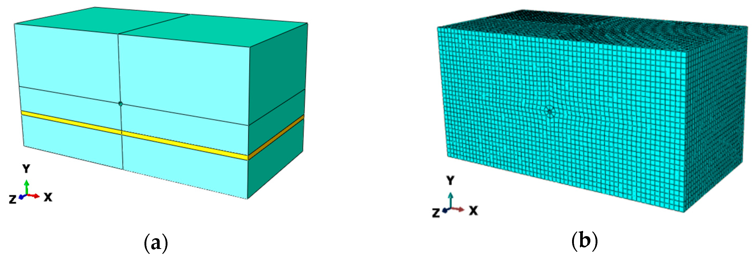
According to the occurrence conditions of a coal seam, a three-dimensional geometric model (Figure 2) with length × width × height of 6 × 3 × 3 m is established. The upper part of the model is coal body unit I, the middle part is tectonic unit Ⅱ, and the lower part is coal body unit Ⅲ. Considering that the external force of the coal system with geological structure is usually applied in the borehole, a borehole with a diameter of 0.1 m is excavated in the center of the model, and the corresponding grid is generated on this basis (Figure 3). The inner boundary condition of the model is the pressure boundary condition acting on the interior of the borehole, and the outer boundary condition is the displacement boundary condition on the left and right sides of the model in the x-direction. The upper and lower sides of the model are displacement boundary conditions in the y-direction; the displacement boundary conditions of the front and rear sides of the model in the z-direction are not set.
In order to investigate the effects of geological structures, such as layering and cracks, on vibration characteristics, it is assumed that each unit within the coal body system containing such geological features behaves as an isotropic homogeneous medium, undergoing purely elastic deformation during vibration. Due to the small elastic deformation of each unit in the coal system with geological structure, the volume and density of each unit in the system remain unchanged during the modal analysis, and its natural frequency is only affected by stiffness, density, and Poisson’s ratio. According to relevant research, confining pressure has an inhibitory effect on the vibration response of rock, but it will not change the resonance frequency of rock samples. The main research object of this paper is the change law of vibration frequency. In order to make the simulation results show a certain regularity and representativeness, the influence of confining pressure on the system in the process of modal analysis is not considered [20].
The numerical simulation process is as follows: ABAQUS modeling is carried out, then the density parameters are defined for the material in the Property function module, then the linear perturbation frequency analysis step is set in ABAQUS/CAE, the field output is set and the operation is submitted, and finally, the frequency and vibration mode are viewed through post-processing. For the purpose of solving the system’s vibration modes, we employ the Lanczos method, which boasts substantial storage capacity and swift computation speeds and is ideally suited for determining the extreme eigenvalues of matrices, thereby fulfilling the practical need for identifying the maximum or minimum eigenvalues in relevant applications [21].

2.2.3. Scheme of Numerical Simulation

In order to obtain the influence of the location, width, and physical properties of geological structures such as layering and fractures on the vibration characteristics of the system, the numerical simulation scheme shown in Table 1 is formulated. Notably, in Table 1, the crack is modeled as a NULL element. However, it is crucial to consider two aspects pertaining to this modeling choice: firstly, the use of a NULL model inherently affects the calculation of the system’s natural frequency; secondly, in real-world geological conditions, cracks often contain some form of filling material. To account for this, the mass density of the cracks in the simulation is assigned a value of 0.01 kg/m3, which serves as a placeholder to represent the potential presence of such fillings.

3. Results

3.1. Selection of Modes

The utilization of low-order frequencies holds paramount importance in the rational implementation of resonance technology, with modal analysis frequencies likewise prioritizing this domain. Combined with the test conditions of this paper, the modal analysis results of scheme S5 are taken as an example to illustrate how to select the vibration mode. The first six-order displacement responses of scheme S5 are shown in Figure 4.
The modal analysis under unconstrained conditions is a free modal analysis, and a mode with a natural frequency of 0 may be obtained, which is called a rigid body mode. Typically, the initial six modes derived from eigenvalue calculations under such unconstrained conditions represent rigid body modes. In the experiment of this paper, the left and right sides of the model are displacement constraints in the x-direction, the upper and lower sides of the model are displacement constraints in the y-direction, and no constraints are set on the front and back sides of the model in the z-direction. Given these constraints, the system inherently possesses a rigid body mode, theoretically exhibiting a natural frequency of zero. However, due to inherent computational inaccuracies, the calculated natural frequency of the rigid body mode may not precisely equal zero but instead approximates this value closely.
For example, the first-order natural frequency obtained by scheme S5 in Figure 4 is 6.56169 × 10⁻⁶ Hz. Consequently, in the subsequent analytical endeavors, the first-order modal natural frequency response outcomes will be excluded from consideration and analysis.
Modal analysis is a powerful tool that not only uncovers the natural frequencies and vibration modes of a system but also quantifies the system’s participation coefficient. This coefficient signifies the cumulative mass motion across all directions within a particular mode, effectively measuring the extent to which a given mode contributes to vibrations in a specific direction. The simulation results of the participation coefficient in the modal analysis of scheme S5 are shown in Table 2.
Combined with Figure 4 and Table 2, it becomes evident that the fourth-order and fifth-order modes are mainly affected by the vibration in the x-axis direction and the second-order, third-order, and sixth-order vibration modes are mainly affected by the combination of x and y directions. When analyzing the influence of the change in bedding position on the vibration characteristics of the system, it is found that the frequency response results of the second, fourth, and fifth orders are basically the same. In order to obtain the influence of bedding position change on the vibration characteristics of the system, the third-order mode and the sixth-order mode are selected for natural frequency and vibration mode analysis under this factor condition. The variation law of each order frequency under other factors is more obvious, so the third-order mode is selected for frequency and vibration mode analysis.
The numerical simulation outcomes reveal that, under the influence of each individual factor, the system’s third-order displacement response results remain essentially consistent, suggesting minimal impact from these factors on the vibration displacement of the coal system with geological structures. Under the condition of each single influencing factor, the third-order displacement response cloud map of the system is no longer specifically analyzed.

3.2. Simulation Results of the Natural Frequency of Layering Coal Systems

3.2.1. Layering Position

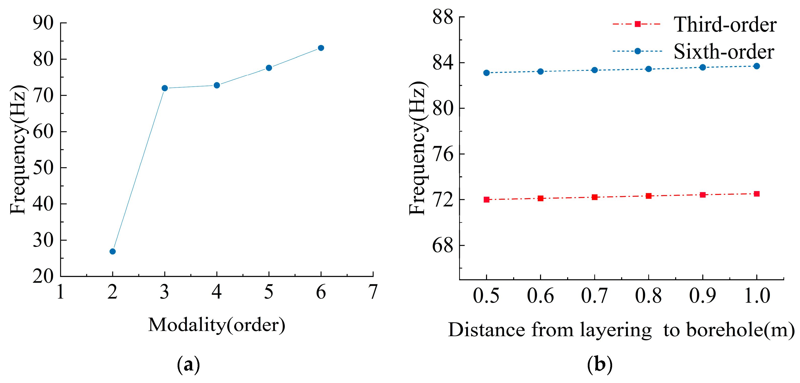
The low-order frequency response results pertaining to the bedding coal system are exhibited in Figure 5. Specifically, Figure 5a demonstrates the trend of frequency variation for each order under scheme S1, which is observed to be consistent with that observed under various other bedding positions. Moreover, the magnitude of each order’s frequency value remains largely uniform across these different configurations.
This consistency stems from the insignificant change in the mass distribution of the coal system with bedding, particularly in the x and z directions, where the influence is minimal. Consequently, negligible variations are observed in the second, fourth, and fifth natural frequencies of the system. The natural frequencies of the third-order and sixth-order systems with bedding coal under different bedding positions are shown in Figure 5b. In Figure 5b, as the distance between the bedding position and the borehole increases, the natural frequency of the system increases. This phenomenon can be attributed to the fact that, despite the overall mass of the system remaining constant, alterations in the bedding position lead to changes in the system’s overall stiffness, thereby influencing its natural frequency.

3.2.2. Layering Thickness

The low-order frequency response results of the bedding coal system under different bedding thickness conditions are shown in Figure 6. As evident in Figure 6a, the trend of frequency variation for each order remains largely consistent across different bedding thicknesses, and the frequency values for each order are fundamentally similar.
The natural frequency of the third-order system of the bedding coal body system under different bedding thickness conditions is shown in Figure 6b. In Figure 6b, with the increase in bedding thickness, the natural frequency of the system decreases. This phenomenon can be attributed to the reduction in the overall mass of the system that accompanies the increase in bedding thickness. However, as the thickness of the bedding increases, the system stiffness decreases faster, so the frequency of the system decreases. This shows that the effect of bedding thickness on the system frequency is mainly achieved by reducing the system stiffness.

3.2.3. Layering Elastic Modulus

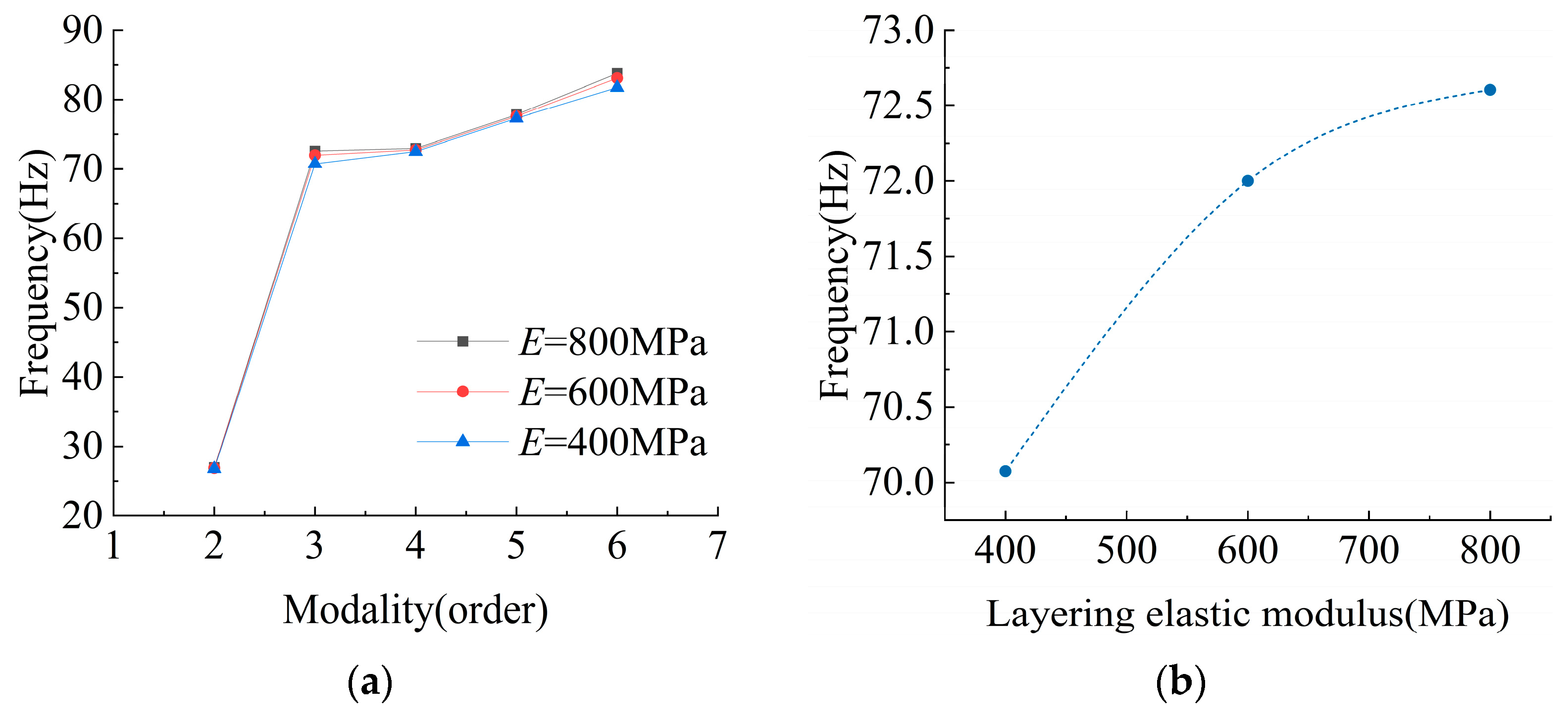
The low-order frequency response results of the layering coal system under different layering elastic modulus conditions are shown in Figure 7. In Figure 7a, the variation trend of each order frequency under different layering elastic modulus conditions is basically the same, and the frequency values of each order are basically the same. In Figure 7b, the natural frequency of the system increases with the increase in the elastic modulus of the bedding. The reason is that with the increase in the elastic modulus of the layering, the stiffness of the system increases, so the influence of the elastic modulus of the bedding on the system frequency is mainly achieved by increasing the stiffness of the system.

3.3. Simulation Results of the Natural Frequency of Coal Systems with Cracks

3.3.1. Crack Width

The low-order frequency response results of the cracked coal system under different crack widths are presented in Figure 8. In Figure 8a, the variation trend of each order frequency of the system under different crack width conditions is basically the same. Under the same order mode, the smaller the crack width is, the higher the frequency of the mode is. In Figure 8b, as the crack width increases, the natural frequency of the system decreases. This phenomenon can be rationalized by the fact that an increase in crack width leads to a commensurate decrease in the system’s stiffness. Consequently, the primary mechanism through which the crack width influences the system’s frequency is by diminishing its overall stiffness.

3.3.2. Crack Length

The outcomes pertaining to the low-order frequency response of the coal system exhibiting varying crack lengths are presented in Figure 9. In Figure 9a, the variation trend of each order frequency of the system under different crack lengths is basically the same. In the same order mode, the smaller the crack length, the higher the frequency of the mode. In Figure 9b, as the crack length increases, the natural frequency of the system decreases. The reason is that as the crack length increases, the stiffness of the system decreases, so the influence of the crack length on the system frequency is mainly achieved by reducing the system stiffness.

4. Discussion

4.1. The Numerical Simulation Results Are Compared with the Results of the Simplified Model

In Section 2.1 of this paper, the vibration model of coal containing geological structure is established. The more theoretical settlement results of the unit division of the coal vibration system with geological structure in the model, the more accurate the theoretical settlement results are. However, the more units are divided, the more difficult the theoretical calculation is. To delve deeper into the intricacies of how factors such as bedding location, width, and physical properties, along with cracks, influence the natural frequency of the coal mass, the vibration model of the coal body with geological structure is simplified and analyzed with numerical simulation results.
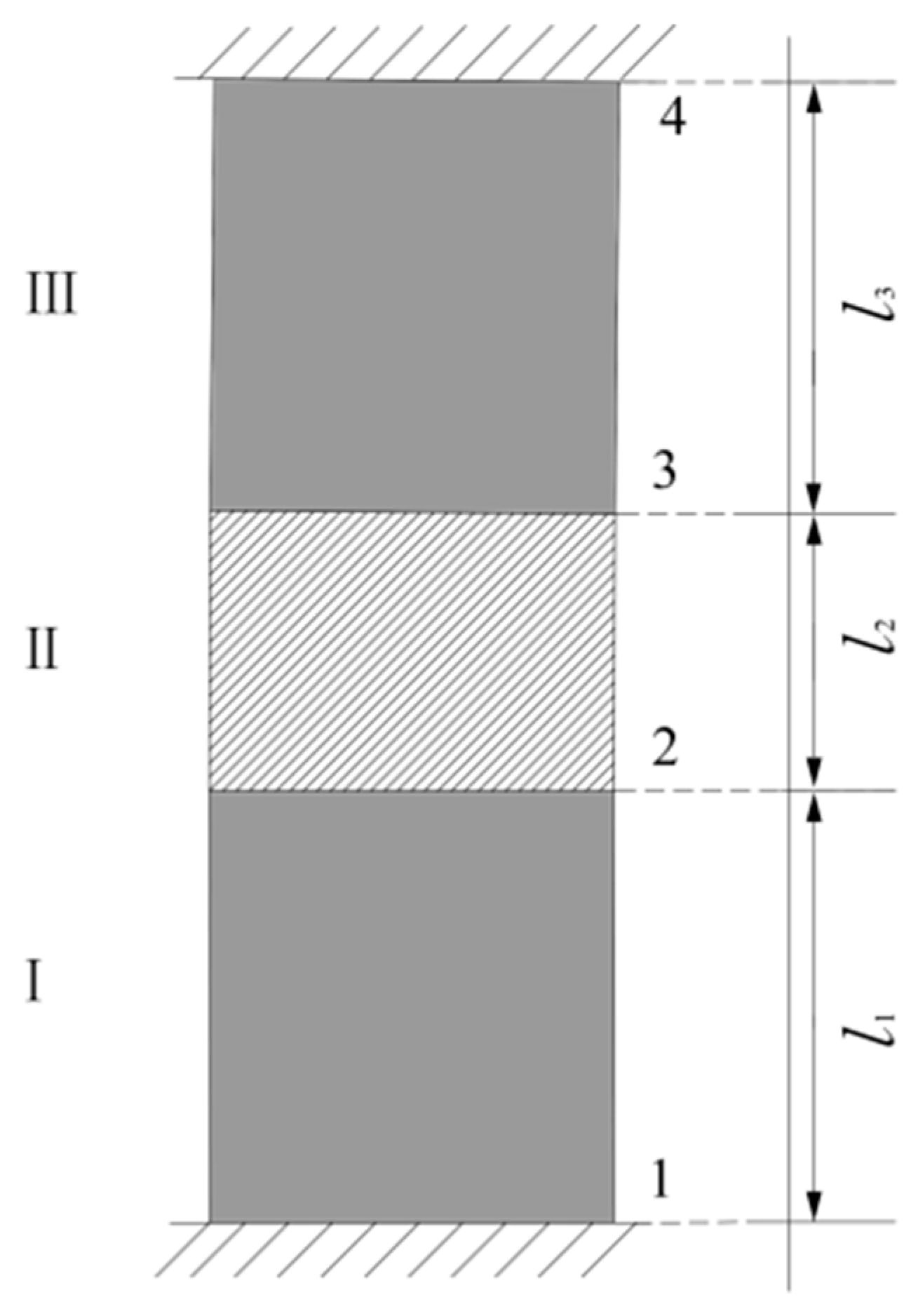
The coal-containing geological structure is simplified as the vibration system of coal coal-containing geological structure shown in Figure 10. In the system, Ⅰ and Ⅲ are coal units, and Ⅱ is a structural unit. 1, 2, 3, and 4 represent the unit node number; node 1 and node 4 adopt the displacement constraint in the y direction, that is, y1 = y4 = 0.
According to the simplified conditions of the model, the undamped vibration equation of the coal body vibration system with geological structure can be simplified as per Equation (8), as follows:
A 1 ρ 1 l 1 2 + A 2 ρ 2 l 2 2 A 2 ρ 2 l 2 2 + A 3 ρ 3 l 3 2 x ¨ 2 x ¨ 3 + A 1 E 1 l 1 + A 2 E 2 l 2 A 2 E 2 l 2 A 2 E 2 l 2 A 2 E 2 l 2 + A 3 E 3 l 3 x 2 x 3 = F 2 F 3
In the formula, A1, A2, and A3 are the cross-sectional areas of coal part Ⅰ, structural part Ⅱ, and coal part Ⅲ, respectively. l1, l2, and l3 are the length of coal part I, structural part Ⅱ, and coal part III, respectively. E1, E2, and E3 are the elastic modulus of coal part I, structural part II, and coal part III, respectively. ρ1, ρ2, and ρ3 are the densities of coal body unit I, tectonic unit Ⅱ, and coal body unit Ⅲ, respectively.
The characteristic equation of Equation (10) is expressed as
( A 1 E 1 l 1 + A 2 E 2 l 2 ) ω 0 2 ( A 1 ρ 1 l 1 2 + A 2 ρ 2 l 2 2 ) A 2 E 2 l 2 A 2 E 2 l 2 ( A 2 E 2 l 2 + A 3 E 3 l 3 ) ω 0 2 ( A 2 ρ 2 l 2 2 + A 3 ρ 3 l 3 2 ) = 0
Since the cross-sectional areas of the coal body part Ⅰ, tectonic part Ⅱ, and coal body part Ⅲ are all equal, A1 = A2 = A3 = A. Coal body part and coal body part III have the same physical characteristics, so the modulus of elasticity of coal body part Ⅰ and coal body part Ⅲ are equal, hence E1 = E3 = EC. The densities of coal body part I and coal body part Ⅲ are equal, hence ρ1 = ρ3 = ρC. When the structural part Ⅱ is bedding, the density of structural part Ⅱ can be expressed as ρ2 = ρS. The elastic modulus of structure part Ⅱ is E2 = ES.
By substituting the above parameters into the characteristic Equation (11) and simplifying it, we can obtain the one-variable quadratic equation about ω 0 2
( E C l 1 + E S l 2 ) ω 0 2 ( ρ C l 1 2 + ρ S l 2 2 ) × ( E C l 3 + E S l 2 ) ω 0 2 ( ρ S l 2 2 + ρ C l 3 2 ) E S l 2 2 = 0
After solving, the vibration frequency of the bedding coal system can be expressed as
ω 0 2 = B ± B 2 4 A C 2 A A = ( ρ C l 1 2 + ρ S l 2 2 ) ( ρ S l 2 2 + ρ C l 3 2 ) B = ( E C l 3 + E S l 2 ) × ( ρ C l 1 2 + ρ S l 2 2 ) ( E C l 1 + E S l 2 ) × ( ρ S l 2 2 + ρ C l 3 2 ) C = ( E C l 1 + E S l 2 ) × ( E C l 3 + E S l 2 ) E S 2 l 2 2
Similarly, the vibration frequency of the coal system with cracks can be obtained as follows:
ω 0 2 = B ± B 2 4 A C 2 A A = ρ C 2 l 1 l 3 2 B = ( E C l 3 + E S l 2 ) × ( ρ C l 1 2 ) ( E C l 1 + E S l 2 ) × ( ρ C l 3 2 ) C = ( E C l 1 + E S l 2 ) × ( E C l 3 + E S l 2 ) E S 2 l 2 2
According to the simplified calculation model of this paper, the parameters in the numerical simulation model are used to solve the natural frequency of the coal body system with geological structure. As evident from Figure 11, the predictive trends of the simplified model’s calculations under varying conditions align closely with those observed in the numerical simulations. However, a notable discrepancy lies in the fact that the natural frequency estimated by the simplified model surpasses that derived from the numerical simulation. The reason is that the simplified model simplifies the coal system with geological structure into three structural units, while the numerical model divides the coal system with geological structure into more than 50,000 units. Obviously, the accuracy of the numerical model is higher, but the calculation method of the simplified model is more general.

4.2. The Influence of Layering Position on the Natural Frequency of Coal System with Geological Structure

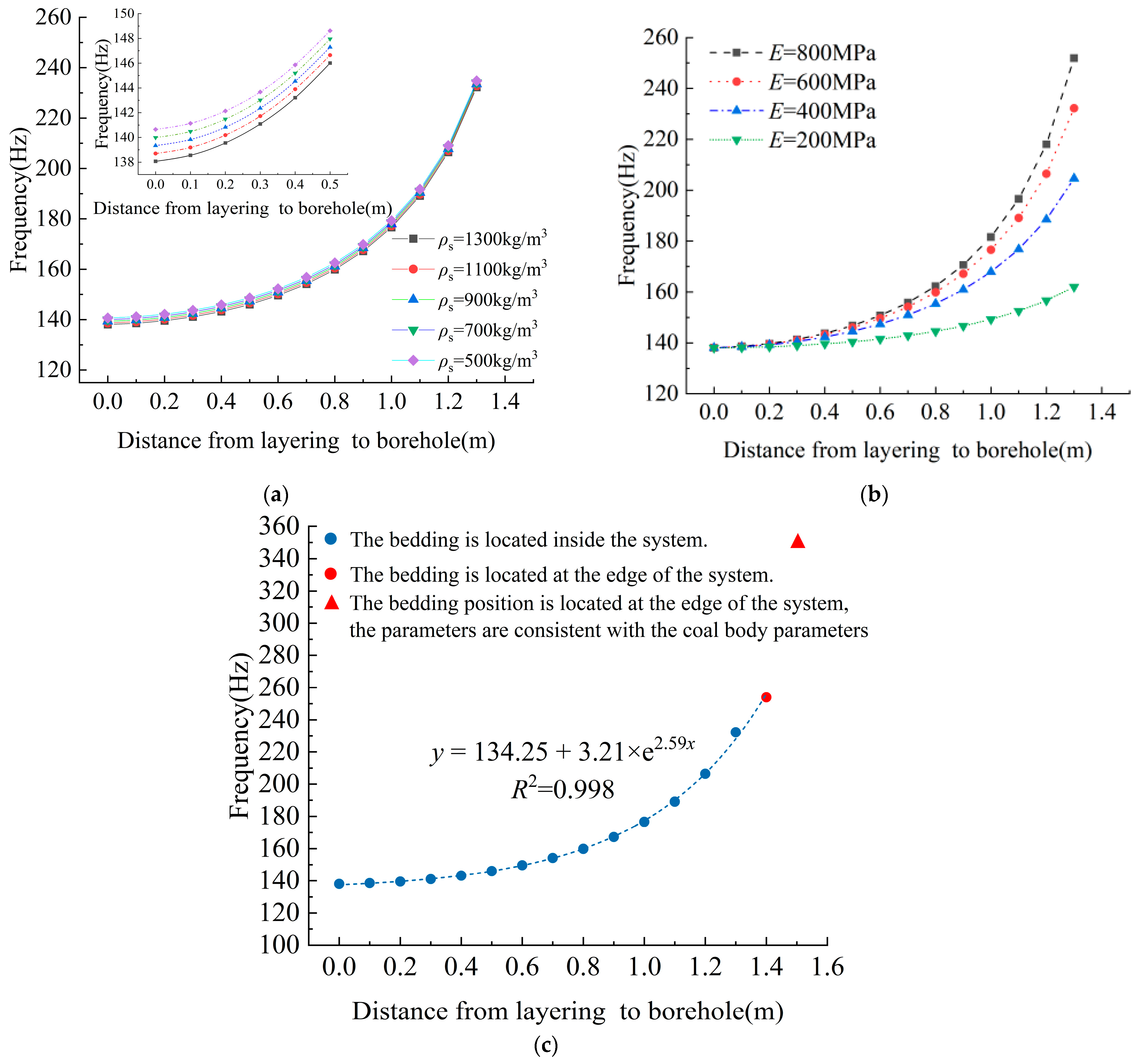
The variation in the natural frequency of the coal system with geological structure with the bedding position is shown in Figure 12. From Figure 12, it can be seen that the natural frequency of the system increases exponentially with the increase in the distance between the bedding and the drilling distance. The borehole position in this study is the geometric center of the xoy plane of the system. When the bedding position is closer to the geometric center of the system, the natural frequency of the system is lower, and the closer to the edge, the higher the natural frequency of the system. Figure 12a shows the variation in natural frequency with bedding position under different bedding density conditions. When the distance between the bedding and the borehole is the same, the larger the bedding density is, the lower the natural frequency of the system is. Figure 12b shows the variation in natural frequency with bedding position under different bedding elastic modulus conditions. When the distance between the bedding and the borehole is the same, the larger the bedding elastic modulus is, the higher the natural frequency of the system is. Figure 12c shows the natural frequency of the system under the condition of bedding limit position. When the distance between the upper boundary of the bedding and the geometric center of the coal body containing geological structure is 0, the minimum natural frequency of the system is 134.25 Hz. When the bedding position is far away from the geometric center of the coal body, the natural frequency of the system increases exponentially.
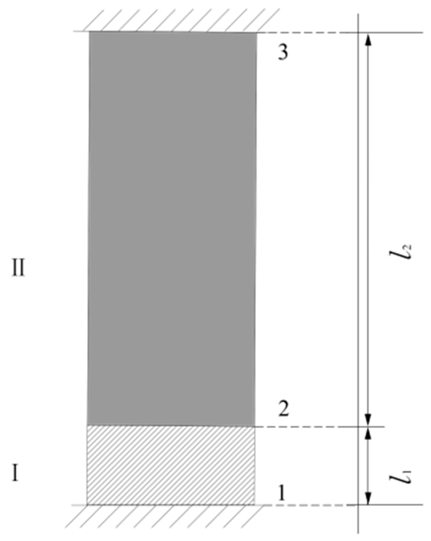
When the bedding is located at the bottom of the coal body system with geological structure, the simplified model of the coal body vibration system with bedding is shown in Figure 13. At this time, the mass matrix and stiffness matrix of the system can be expressed as
M = A 1 ρ 1 l 1 2 A 1 ρ 1 l 1 2 + A 2 ρ 2 l 2 2 A 2 ρ 2 l 2 2 ,   K = k 11 1 k 12 1 k 21 1 k 22 1 + k 22 2 k 23 2 k 32 2 k 33 2
In the model shown in Figure 13, node 1 and node 3 are displacement constraints, so the undamped vibration equation of the system can be expressed as
( A 1 ρ 1 l 1 2 + A 2 ρ 2 l 2 2 ) × x ¨ 2 + ( A 1 E 1 l 1 + A 2 E 2 l 2 ) × x 2 = F ( t )
The characteristic equation can thus be obtained as
( A 1 E 1 l 1 + A 2 E 2 l 2 ) ω 2 ( A 1 ρ 1 l 1 2 + A 2 ρ 2 l 2 2 ) = 0
This can be simplified to obtain the following formula:
ω 2 = ( E S l 1 + E C l 2 ) / ( ρ S l 1 2 + ρ C l 2 2 )
By substituting the relevant physical parameters into Equation (18), the natural frequency of the system can be obtained when the bedding is located at the bottom of the coal system containing geological structure, f0 = 253.93 Hz. At this time, the natural frequency of the coal system containing bedding reaches the maximum. Further replacing the bedding with coal and substituting the relevant physical parameters into Equation (18), the natural frequency of the system is 352.73 Hz when there is no bedding in the system. At this juncture, the natural frequency of the system is notably higher than that of the coal system with bedding, signifying a substantial reduction in the system’s natural frequency when layering is present. The numerical calculation results of the natural frequency of the system when the bedding is located at the boundary of the system and the physical parameters of the bedding are replaced by the coal and rock parameters, as shown in Figure 12c.
According to the analysis of Figure 12, the natural frequency of the system under different bedding positions conforms to the following variation rules:
y = AeBx + C
In the formula, y is the system response frequency and x is the distance from the bedding to the borehole. A, B, and C are coefficients. According to the fitted Equation (19), it can be seen that (1) the natural frequency of the system increases exponentially with the increase in the distance from the bedding to the borehole. (2) The coefficient C in the formula represents the natural frequency of the system when the distance between the upper boundary of the bedding and the geometric center of the coal body system with geological structure is 0. (3) The coefficients A, B, and C in the formula are related to the elastic modulus and density of coal and bedding.

4.3. The Influence of Geological Structure Physical Parameters on the Natural Frequency of Coal System with Geological Structure

4.3.1. The Influence of Cracks and Bedding on the Natural Frequency of Coal System with Geological Structure

In this paper, the numerical simulation and theoretical calculation of the natural frequency of bedding thickness and crack width are realized by setting the physical parameters of bedding and crack. Consequently, a comparative analysis of the natural frequencies of bedding and cracks under varying elastic modulus and density conditions becomes feasible.
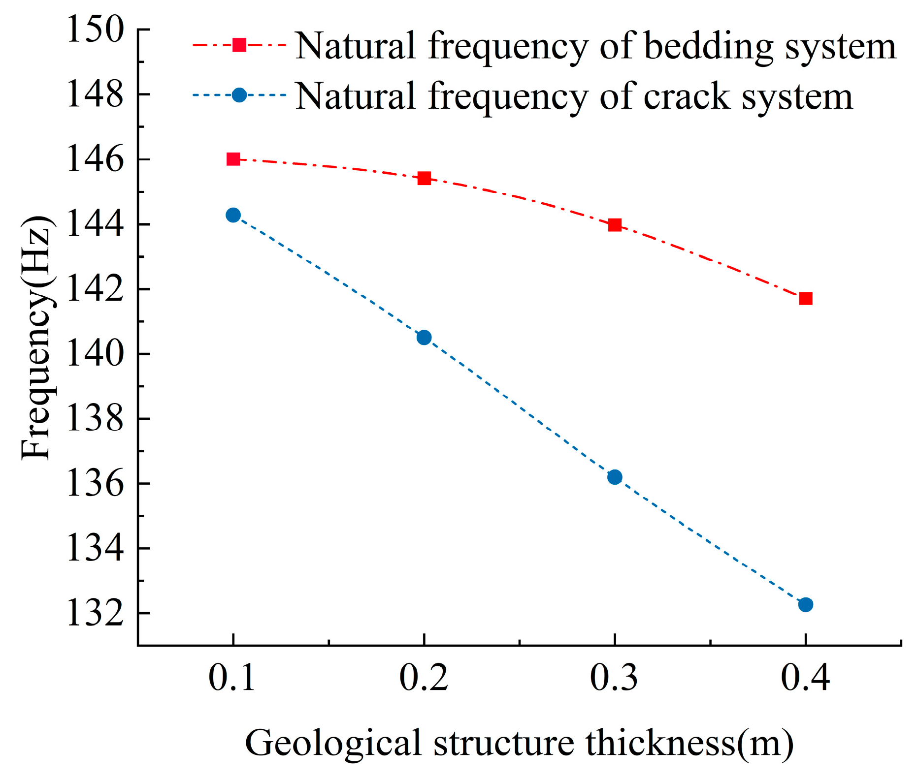
As discernible from Figure 14, the system’s natural frequency experiences a decline with the augmentation of both bedding thickness and crack width. When the bedding thickness increases from 0.1 m to 0.4 m, the natural frequency of the system decreases from 146.006 Hz to 141.707 Hz. When the crack thickness increases from 0.1 m to 0.4 m, the natural frequency of the system decreases from 144.28 Hz to 132.262 Hz. Notably, when the bedding thickness equals the crack width, the fracture system exhibits a lower natural frequency compared to the bedding system. Furthermore, within an identical range of variation for both crack width and bedding thickness, the coal system with cracks undergoes a more pronounced change in natural frequency than the coal system with bedding.
The primary contributor to these observed differences lies in the disparity of physical parameters between cracks and bedding. In this paper, the elastic modulus of the bedding part is 600 MPa, the density is 1300 kg/m2, the elastic modulus of the fracture part is 200 MPa, and the density is 0.1 kg/m2. It can be seen that the physical parameters of the structural part will have a certain impact on the size and variation in the natural frequency of the system.

4.3.2. The Influence of Layering Elastic Modulus on the Natural Frequency of Coal System with Geological Structure

The numerical simulation results (Figure 7) show that the natural frequency of the system increases with the increase in the elastic modulus of the bedding.
The calculation formula of the natural frequency of the coal and rock mass system is as follows:
ω 0 = k m
In the formula, ω 0 is the inherent angular frequency of the object, rad/s. m is the mass of the system, kg. It is assumed that the coal-rock mass system is an idealized model, and its stiffness can be obtained by the stiffness formula of elastic material, that is
k = E A L
In the formula, L is the length of the rock block, m. E is the elastic modulus of rock, MPa. A is the cross-sectional area of the rock block, m2.
By substituting Equation (21) into Equation (20) and simplifying it, we can obtain the following:
ω 0 = E ρ L 2
Equation (22) shows that under the condition that other factors remain unchanged, the larger the elastic modulus of the system, the higher the natural frequency of the system. Generally, the elastic modulus of the bedding part of the coal system with geological structure is smaller than that of the coal part. Consequently, as the elastic modulus of the bedding rises, the overall stiffness of the system intensifies. When the elastic modulus of the bedding part is equal to the elastic modulus of the coal body, the frequency response of the system will also reach the maximum value.
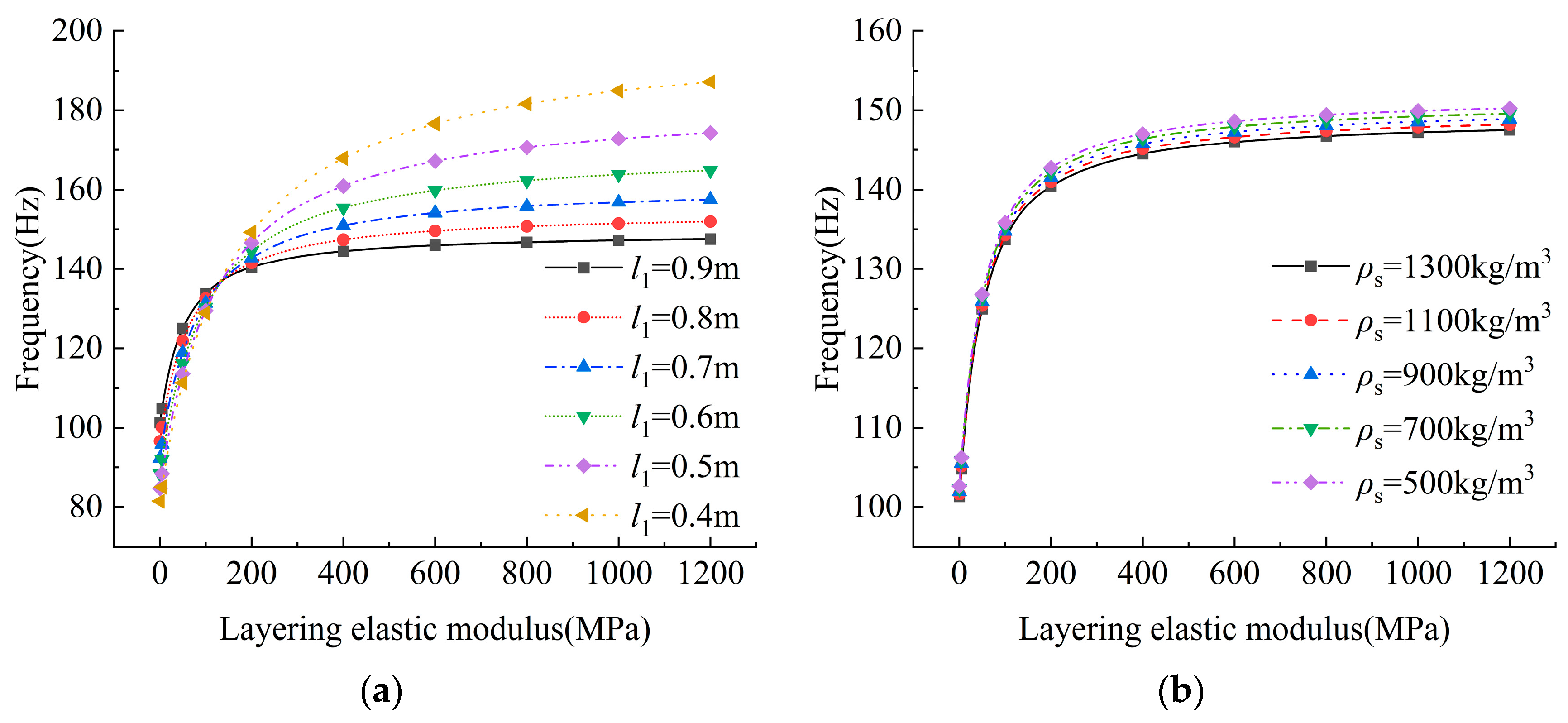
By changing the elastic modulus of the bedding, the variation in the natural frequency of the system with the elastic modulus can be obtained by the theoretical calculation method (Figure 15). Figure 15a shows the variation in natural frequency with the elastic modulus of bedding under different bedding positions. When the elastic modulus of bedding is the same, the farther the distance from the bedding to the borehole, the lower the natural frequency of the system is. Figure 15b is the variation in the natural frequency with the elastic modulus of the bedding under different bedding densities. When the elastic modulus of the bedding is the same, the smaller the bedding density, the higher the natural frequency of the system.
According to Figure 15, it can be seen that the change in the natural frequency of the system with the elastic modulus of the bedding conforms to the following rules:
y = A · x B + C  
In the formula, y is the system frequency; x is the elastic modulus of bedding; and A, B, and C are coefficients. According to Figure 15 and Equation (23), it can be seen that (1) the natural frequency of the system increases in the form of a power function with the increase in the elastic modulus of the bedding. The coefficient B is less than 1, which indicates that the natural frequency of the system increases rapidly when the elastic modulus of the bedding is small, and the natural frequency of the system increases slowly when the elastic modulus of the bedding is large. (2) Coefficients A and B are related to the location and density of bedding. (3) The coefficient C is related to the density and elastic modulus of coal rock.

4.4. The Influence of Geological Structure Thickness on the Natural Frequency of Coal System with Geological Structure

In this paper, the range of bedding thickness in numerical simulation is 0.1 m~0.4 m. The outcomes of these simulations reveal a consistent trend: the system’s frequency diminishes as the bedding thickness increases. To further explore this relationship, we extended the thickness range to 0.1 m to 2.1 m, using the same relevant parameters from the initial simulations, and employed a theoretical calculation method to analyze the system’s natural frequency variations with respect to bedding thickness. The results are presented in Figure 16. It can be seen from Figure 16 that the system frequency decreases first and then increases with the increase in bedding thickness. There are differences between theoretical calculation results and numerical simulation results. The numerical simulation results show that the system frequency decreases with the increase in bedding thickness. The theoretical calculation results show that the system frequency decreases first and then increases with the increase in bedding thickness.
The reason for this difference should be explained by Equation (22). In Equation (22), the natural frequency of the system increases with the increase in the elastic modulus and decreases with the increase in the overall density of the system. As the bedding thickness augments, the system experiences a reduction in both its elastic modulus and density. Therefore, the changing trend of the system frequency depends on the ratio of the elastic modulus to the density. If the modulus of elasticity decreases to a large extent it causes the system frequency to decrease, and if the modulus of elasticity decreases to a small extent, it causes the system frequency to increase. In summary, the theoretical calculation results and numerical simulation results are not contradictory. When the variation range of bedding thickness is 0.1 m~1.0 m, the natural frequency of the system decreases. When the variation range of bedding thickness is 1.0 m~2.1 m, the system frequency increases.
In addition, according to Figure 16, it can also be seen that when the thickness of the bedding is the same, the greater the density of the bedding, the smaller the natural frequency of the system.
The influence of crack width on the natural frequency of the system is similar to that of bedding thickness. The numerical simulations demonstrate that an increase in crack width leads to a corresponding decrease in the system’s natural frequency. From Equation (22), with the increase in crack width, the elastic modulus and density of the system decrease, so the changing trend of the system frequency depends on the ratio of elastic modulus and density. The theoretical calculation results also confirm this view (Figure 17). It can be seen from Figure 17 that when the crack width increases from 0.1 m to 0.9 m, the system frequency decreases. When the crack thickness increases from 0.9 m to 2.1 m, the system frequency increases. When the crack width is 0.9 m, the natural frequency of the system reaches the minimum value. Moreover, according to Figure 17, it can also be seen that at the same crack width, the higher the crack elastic modulus, the higher the intrinsic frequency of the system.

5. Conclusions

  • When a single influencing factor among bedding position, bedding thickness, bedding physical properties, crack width, and crack length is varied, the distribution of the displacement vibration response cloud diagram for the coal body vibration system with geological structures remains largely consistent. Under the influence of every single factor, the difference in vibration displacement of coal system with geological structure is small;
  • The natural frequency of the system increases exponentially with the increase in the distance between the bedding and the geometric center of the coal system with geological structure. When the distance between the upper boundary of the bedding and the geometric center of the coal system with geological structure is 0, the natural frequency of the system is the smallest. When the bedding is located at the edge of the system, the natural frequency of the system is the largest. When the bedding physical parameters at the edge of the system are replaced by coal and rock parameters, the natural frequency of the system is significantly larger than that of the bedding coal system, that is, when there is bedding in the system, the natural frequency of the system is significantly reduced;
  • When the bedding thickness is the same as the crack width, the natural frequency of the fracture system is lower than that of the bedding system. When the variation range of crack width and bedding thickness is the same, the natural frequency of the coal system with cracks changes more significantly than that of the coal system with bedding. The natural frequency of a coal system with geological structure increases in the form of a power function with the increase in bedding elastic modulus, and its change conforms to the following law: y = A × xB+ C. The parameter B less than 1 indicates that the natural frequency of the system increases rapidly when the elastic modulus of the bedding is small, and the natural frequency of the system increases slowly when the elastic modulus of the bedding is large;
  • The natural frequency of the coal system with geological structures diminishes as crack length intensifies. This decrease stems from the reduced strength and stiffness of the system as crack length expands, ultimately leading to a lowering of the system’s natural frequency;
  • The natural frequency of the coal system with geological structures initially decreases and subsequently increases with the augmentation of bedding thickness and crack width. As the thickness of the structure increases, the stiffness and density of the system decrease. At the beginning of the change, the density of the system changes little, and the natural frequency of the system decreases with the decrease in the stiffness of the system. However, as the structural thickness increases further, significant changes in system density commence, and the natural frequency of the entire system subsequently increases, primarily influenced by these density alterations. The trend of natural frequency variation and the location of extreme points are intimately linked to the ratio of the geological structure’s elastic modulus to its density;
  • This study bears certain limitations. Firstly, due to workload constraints and other factors, only the effects of bedding and fractures, two types of geological structures, on the natural frequency of coal seam systems were considered. In addition, due to the existing laboratory test conditions, only small-sized briquettes and raw coal can be tested for vibration, and the vibration test of raw coal under large-scale and actual formation conditions cannot be realized. The vibration test results of small-sized briquettes and raw coal are quite different from the vibration characteristics of coal seams under actual formation conditions. Therefore, this paper only studies its law by combining theoretical derivation and numerical simulation.

Author Contributions

Conceptualization, G.X.; methodology, G.X.; validation, G.X. and S.L.; formal analysis, S.L.; investigation, S.L.; writing—original draft preparation, G.X. and S.L.; writing—review and editing, G.X. and S.L.; visualization, S.L.; supervision, H.J.; project administration, G.X.; funding acquisition, G.X. The published version of the manuscript has been read by and obtained the agreement of all authors. All authors have read and agreed to the published version of the manuscript.

Funding

This work was financially supported by the National Key Research and Development Program of China (2018YFC0807805) and the Natural Science Basic Research Program of Shaanxi (2019JM-072).

Institutional Review Board Statement

Not applicable.

Informed Consent Statement

Not applicable.

Data Availability Statement

The authors confirm that the data supporting the findings of this study are available within the article.

Conflicts of Interest

The authors declare no conflicts of interest.

References

  1. Yin, W.L.; Pan, Y.S.; Li, Z.H. Study on the relationship between rock burst and microseismic factors. China Saf. Sci. J. 2017, 27, 109–114. [Google Scholar] [CrossRef]
  2. Jang, Y.D.; Li, Y.; Cui, Y.Z. Experimental study on characteristics of coal reservoir permeability under acoustic wave. J. China Coal Soc. 2011, 33, 21–24. [Google Scholar] [CrossRef]
  3. Yi, J. A Research on Mechanism and Technological Principle of Enhancing Coalbed Gas Extraction Rate by Ultrasonic Vibrating. Ph.D. Thesis, Chongqing University, Chongqing, China, 2007. [Google Scholar]
  4. Feng, J.; Yan, T.; Cao, Y.; Sun, S. Ultrasonic-Assisted Rock-Breaking Technology and Oil and Gas Drilling Applications: A Review. Energies 2022, 15, 8394. [Google Scholar] [CrossRef]
  5. Liu, B.X.; Xian, X.F.; Liu, X.R. Coal gas outburst induced by blasting. CMM 2000, 9, 89–91. [Google Scholar]
  6. Li, S.G.; Zhao, Y.; Xu, M.G. Gas porosity formula under low frequency vibration and its testing analysis. J. China Coal Soc. 2016, 41, 612–619. [Google Scholar] [CrossRef]
  7. Akhymbayeva, B.S.; Akhymbayev, D.G.; Nauryzbayeva, D.K.; Mauletbekova, B.K. The Process of Crack Propagation during Rotary Percussion Drilling of Hard Rocks. Period. Eng. Nat. Sci. 2021, 9, 392–416. [Google Scholar] [CrossRef]
  8. Wen, Z.; Zhang, L.; Wei, J.; Wang, J.; Zhang, J.; Jia, Y.; Ren, Y. Study on natural frequency response characteristics of coal vibration excited by simple harmonic wave. Sci. Rep. 2022, 35, 41–45. [Google Scholar] [CrossRef] [PubMed]
  9. Wang, Z.; Xu, Y.J.E. Review on application of the recent new high-power ultrasonic transducers in enhanced oil recovery field in China. Energy 2015, 89, 259–267. [Google Scholar] [CrossRef]
  10. Bei, J.P. Research and Application of Enhanced Oil Recovery Technology of Artificial High-Power Monochromatic Wave in Low Permeability Reservoir. Master’s Thesis, China University of Petroleum, Qingdao, China, 2009. [Google Scholar] [CrossRef]
  11. Zang, S.; Wang, J.G. Study on variation law of natural vibration frequency of coal under water erosion condition. Saf. Coal Mines 2019, 50, 6–9. [Google Scholar]
  12. Li, F.; Wang, G.; Xiang, G.; Tang, J.; Ren, B.; Chen, Z. Vibration Response of the Interfaces in Multi-Layer Combined Coal and Rock Mass under Impact Load. Processes 2023, 11, 306. [Google Scholar] [CrossRef]
  13. Yan, L.P. Study on vibration characteristics of fractured rock and finite element analysis. J. Yangtze Univ. (Nat. Sci. Ed.) 2019, 16, 104–108. [Google Scholar] [CrossRef]
  14. Li, C.W.; Sun, X.Y.; Gao, T.B. Research on the variation characteristics of natural frequency in the process of coal and rock vibration damage. J. China Coal Soc. 2015, 40, 1834–1844. [Google Scholar] [CrossRef]
  15. Gao, T.B. Coal Experimental Study on Forced Vibration Response and Fracture Characteristics. Ph.D. Thesis, China University of Petroleum, Master’s Thesis, China University of Mining and Technology. Beijing, China, 2013. [Google Scholar]
  16. Li, C.; Liu, J.; Wang, C. Spectrum characteristics analysis of microseismic signals transmitting between coal layering. Safety Sci. 2012, 50, 761–767. [Google Scholar] [CrossRef]
  17. Ren, Y.J.; Wei, J.P.; Wen, Z.H. Experimental research on influencing factors of natural frequency of coal. China Saf. Sci. J. 2021, 31, 104–111. [Google Scholar] [CrossRef]
  18. Wei, J.P.; Zhang, J.S.; Wen, Z.H. Study on the natural frequency characteristics of coal based on the influence of bedding and coal rank. J. Henan Polytech. Univ. (Nat. Sci.) 2023, 42, 1–8. [Google Scholar] [CrossRef]
  19. Zhu, Y.K.; Yu, L.Q.; Zhou, J.C. Modal analysis of truss robot based on ABAQUS. J. Wuhan Text. Univ. 2022, 35, 41–45. [Google Scholar]
  20. Wang, M.; Xuan, L.; Liu, W.; Feng, J.; Wang, H. Numerical Simulation of Rock Vibration Response under Ultrasonic High-Frequency Vibration with High Confining Pressure. Processes 2024, 12, 1394. [Google Scholar] [CrossRef]
  21. Cao, J.H. Natural frequency analysis of vibrating screen based on Lanczos modal analysis method. J. Liaodong Univ. (Nat. Sci. Ed.) 2013, 20, 125–128. [Google Scholar] [CrossRef]
Figure 1. Vibration system model of a coal-containing geological structure.
Sustainability 16 07390 g001
Figure 2. Geometric model of a coal system with a geological structure. (a) Geometric model; (b) Boundary condition.
Sustainability 16 07390 g002
Figure 3. Numerical model of a coal system with a geological structure. (a) Numerical model; (b) Mesh subdivision. Note: Green represents the coal part. Yellow represents the structure part.
Sustainability 16 07390 g003
Figure 4. The displacement response cloud diagram of the first six modes of scheme S5. (a) Cloud diagram of the displacement response; (b) Displacement response cloud in the x direction; (c) Displacement response cloud in the y direction.
Sustainability 16 07390 g004
Figure 5. Low-order frequency response results of the coal system with bedding under different bedding positions. (a) Scheme S1 (l2 = 0.5 m); (b) The third-order and sixth-order frequency response results.
Sustainability 16 07390 g005
Figure 6. Low-order frequency response results of coal system with bedding under different bedding positions. (a) Different layering thickness; (b) The third-order and sixth-order frequency response results.
Sustainability 16 07390 g006
Figure 7. Low-order frequency response results of layering coal system under different bedding elastic modulus conditions. (a) Different layering elastic modulus; (b) The third-order and sixth-order frequency response results.
Sustainability 16 07390 g007
Figure 8. Low-order frequency response results of cracked coal system under different crack width conditions. (a) Different crack width; (b) The third-order and sixth-order frequency response results.
Sustainability 16 07390 g008
Figure 9. Low-order frequency response results of cracked coal system under different crack length conditions. (a) Different crack length; (b) The third-order and sixth-order frequency response results.
Sustainability 16 07390 g009
Figure 10. Simplified model of vibration system of coal containing a geological structure. Note: Ⅰ—coal unit, Ⅱ—geological structural unit, Ⅲ—coal unit.
Sustainability 16 07390 g010
Figure 11. Calculation results of the natural frequency of the coal system with geological structure.
Sustainability 16 07390 g011
Figure 12. The variation law of the natural frequency of bedding coal system with bedding position. (a) Different layering density; (b) Elastic modulus of different layering; (c) The limit position of layering.
Sustainability 16 07390 g012
Figure 13. Simplified model of vibration system of coal-containing bedding. Note: Ⅰ—geological structural unit, Ⅱ—coal unit.
Sustainability 16 07390 g013
Figure 14. The variation law of natural frequency of the system under different bedding thickness and crack width conditions.
Sustainability 16 07390 g014
Figure 15. The variation in the natural frequency of the system with the elastic modulus. (a) different distances from bedding to borehole and (b) different layering density.
Sustainability 16 07390 g015
Figure 16. Changing rule of system frequency with lamination thickness.
Sustainability 16 07390 g016
Figure 17. Change rule of system frequency with crack width.
Sustainability 16 07390 g017
Table 1. Numerical simulation program of the vibration characteristics of coal body systems with geological formations.
Geotectonic TypeProgram NumberDistance from Borehole/mThickness
l2
/m
Coal Part III
l1/m
Length
/m
Physical Parameters of Geological StructurePhysical Parameters of Coal Part
Elastic Modulus
/MPa
Poisson RatioDensity/kg∙m−3Elastic Modulus/MPaPoisson RatioDensity/kg∙m−3
LayeringS10.50.10.966000.32130012000.31430
S20.60.10.866000.32130012000.31430
S30.70.10.766000.32130012000.31430
S40.80.10.666000.32130012000.31430
S50.90.10.566000.32130012000.31430
S610.10.466000.32130012000.31430
S70.50.20.866000.32130012000.31430
S80.50.30.766000.32130012000.31430
S90.50.40.666000.32130012000.31430
S1010.10.968000.32130012000.31430
S1110.10.964000.32130012000.31430
CrackF10.50.10.962000.320.0112000.31430
F20.50.20.862000.320.0112000.31430
F30.50.30.762000.320.0112000.31430
F40.50.40.662000.320.0112000.31430
F50.50.10.922000.320.0112000.31430
F60.50.10.932000.320.0112000.31430
F70.50.10.942000.320.0112000.31430
F80.50.10.952000.320.0112000.31430
Table 2. The simulation results of the participation coefficient in scheme S5 modal analysis.
Modality
(Order)
x Translationy Translationz Translationx Rotationy Rotationz Rotation
First3.42448 × 10−141.42392 × 10−16277.410.80134−9.82013 × 10−122.25384 × 10⁻¹⁴
Second2.69465 × 10−7−6.54534 × 10−75.05691 × 10−127.78754 × 10−5517.78−3.05888 × 10⁻⁶
Third−2.14221 × 10⁻⁶−5.85734 × 10⁻⁷−1.28878 × 10−11287.76−2.28406 × 10−42.06681 × 10−5
Fourth1.32194 × 10−42.22175 × 10⁻⁶−5.95841 × 10−110.454661.96831 × 10−4−1.75318 × 10⁻⁴
Fifith241.98−6.53276 × 10⁻⁷−5.43883 × 10−114.96011 × 10−6362.971.5278
Sixth4.21964 × 10−5−1.66600 × 10−61.47560 × 10−101.44118 × 10⁻⁴−1.7623−6.05567 × 10⁻⁵
Disclaimer/Publisher’s Note: The statements, opinions and data contained in all publications are solely those of the individual author(s) and contributor(s) and not of MDPI and/or the editor(s). MDPI and/or the editor(s) disclaim responsibility for any injury to people or property resulting from any ideas, methods, instructions or products referred to in the content.