Article

Experimental Investigation of a Water–Air Heat Recovery System

by
Robert Ștefan Vizitiu
1,
Ștefănica Eliza Vizitiu
1,*,
Andrei Burlacu
1,*,
Chérifa Abid
2,
Marius Costel Balan
1 and
Nicoleta Elena Kaba
3
1
Faculty of Civil Engineering and Building Services, “Gheorghe Asachi” Technical University of Iasi, 700050 Iasi, Romania
2
CNRS, IUSTI UMR 7343, Aix-Marseille Université, 13453 Marseille, France
3
Faculty of Civil Engineering, Politehnica University of Timisoara, 300223 Timișoara, Romania
*
Authors to whom correspondence should be addressed.
Sustainability 2024, 16(17), 7686; https://doi.org/10.3390/su16177686
Submission received: 24 July 2024 / Revised: 31 August 2024 / Accepted: 2 September 2024 / Published: 4 September 2024
(This article belongs to the Section Energy Sustainability)

Abstract

:
The implementation of energy-saving measures has a substantial and beneficial impact on the preservation of energy resources as well as the reduction of carbon dioxide emissions. This study focuses on the design and experimental analysis of a water-to-air heat recovery system aimed at capturing waste heat from wastewater and transferring it to a fresh cold air stream using heat pipe technology. The research problem addressed in this study is the efficient recovery of low-grade thermal energy from wastewater, which is often underutilized. The prototype heat recovery unit was designed, manufactured, and tested in the laboratory to assess its performance across various operating conditions. The experimental setup included a system where the primary agent, hot water, was heated to 60 °C and circulated through the evaporator section of the heat recovery unit, while the secondary agent, fresh air, was forced through the condenser section. The system’s performance was evaluated under different air velocities, ranging from 3.5 m/s to 4.5 m/s, corresponding to airflow rates of 207.1 m3/h and 268.6 m3/h, respectively. The study employed analytical methods alongside empirical testing to determine the effectiveness of the heat recovery system, with the global heat transfer coefficient calculated for different scenarios. The efficiency of the system varied between 25% and 51.6%, depending on the temperature and speed of the fresh air stream. The most significant temperature difference observed between the inflow and outflow of the fresh air stream was 16.8 °C, resulting in a thermal output of 1553 W. Additionally, the average (mean) overall heat transfer coefficient of the unit was calculated to be 49 W/m2 K, which aligns with values reported in the literature for similar systems. The results demonstrate the potential of the designed system for practical applications in energy conservation and carbon emission reduction.

1. Introduction

In the context of finding sustainable solutions to mitigate the impact of climate change, reducing global carbon dioxide (CO2) emissions to net zero by 2050 is an urgent issue that requires immediate attention. A recent analysis conducted by the IEA in 2022 revealed that energy-related CO2 emissions escalated to an all-time high in 2021, soaring by 6% compared to the previous year [1]. As pointed out in the IEA’s 2021 investigation, major changes are needed in the production of energy, transportation, as well as consumption if we are going to achieve this ambitious objective by 2050 [2]. In other words, to accomplish this objective, a comprehensive and strategic approach is required that encompasses all aspects of the energy sector, from production to consumption. Waste heat recovery has been highlighted as a viable strategy for lowering carbon emissions and supporting sustainability [3]. This approach not only lowers carbon emissions but also increases energy efficiency and contributes to the system’s overall sustainability by capturing wasted heat from various industrial operations and converting it back into useful energy [4]. The increasing popularity of waste heat recovery systems is reflected in the numerous studies that have focused on improving their efficiency and effectiveness in capturing and repurposing surplus heat [5].
To capture, recover, and exchange heat in industrial processes, various systems have been developed, such as plate heat exchangers [6], waste heat boilers [7], heat pipe systems [8], and others [9]. These types of technologies play an important role in increasing long-term sustainability and energy efficiency in a variety of industries as they allow thermal waste from ongoing operations to be recovered and converted into use for other purposes like heating and the production of energy.
Due to their superior features when it comes to heat pipes, heat pipe heat exchangers stand out among these technologies [10]. Heat-pipe-based heat recovery systems have been extensively investigated in recent years for their potential to recover waste heat in various sectors. Successful applications have been reported in areas such as heating, ventilation and air conditioning [11,12,13], photovoltaic–thermal systems [14,15], the steel industry [16,17], the ceramic kiln industry [18], the aluminum industry [19], thermal storage [20], and other sectors.
In light of the aforementioned, heat pipes possess vast potential for implementation in various applications of waste heat recovery. Numerous studies have offered valuable insights into the effective utilization of heat pipes for this purpose, highlighting their versatility. As identified in the literature, a broad variety of heat pipe heat exchangers are available, each adapted to a particular application.
In a recent study, ref. [21] evaluated the performance of a heat pipe flue gas waste heat utilization system installed in front of the inlet of an electrostatic precipitator of a boiler. The results showed that the heat exchanger achieved an average flue gas temperature drop of 26.3 °C, a reduced temperature deviation of 8.1 °C, and had the potential to reduce coal consumption by 1.3 g/(kW h) through increased condensate temperature. In a relevant study, ref. [22] performed research aiming to design and construct a heat pipe heat exchanger to recover waste energy from flue gas in a city gate station and to evaluate the resulting energy savings. The results showed that the use of heat pipes reduced natural gas consumption by 510,132 SCM per year and prevented 756 tons of CO2 from being emitted from the city gate station annually.
Given the extensive potential demonstrated by heat pipes in waste heat recovery applications, it is worth noting a study conducted by [23] that focused on the development and analysis of a heat pipe inserted plate air–air heat exchanger. The experimental results highlighted the improved heat transfer performance and high temperature effectiveness achieved by the heat exchanger. The maximum temperature effectiveness of the heat exchanger reached 70% in summer conditions and the average annual energy efficiency ratio while running in different cities was between 3.67 and 12.72.
In the ETKINA project [24], heat pipe heat exchangers (HPHEs) are identified as a suitable solution for heat recovery in various industrial applications, including aluminum, steel, and ceramics. The project focuses on achieving a 40% waste heat recovery from exhaust streams, ensuring a quick payback period. The anticipated results include annual recoveries of up to 597 MWh, 3020 MWh, and 4003 MWh in each industry, resulting in a substantial decrease in CO2 emissions. Building upon previous work in the ceramic industry, ref. [25] further investigated the thermal performance of a heat pipe heat exchanger in a ceramic kiln. Their comprehensive study, combining theoretical, experimental, and numerical analyses, confirms the effectiveness of the system in recovering 876 MWh per year. The results demonstrate quick response times and great thermal performance, proving the heat recovery system’s potential even further.
Heat pipes offer superior heat transfer performance and have been integrated into solar systems to overcome limitations [26] as a result of numerous studies showing their advantages. Also, by combining heat pipes with phase change materials (PCM), overall heat transfer rates can be enhanced, leading to greater efficiency and performance in various thermal energy applications [27].
In their study, [28] designed a new solar air collection system that uses flat-plate micro heat pipe arrays and evaluated its thermal performance. The experiments were conducted at different volume flow rates to analyze the energy and exergy aspects. The key findings indicated that the system exhibited good heat storage and release performance, with an average collection efficiency of 35.8% and average storage efficiencies of 67.5% and 87.5% for latent heat storage units I and II, respectively.
In another study, [29] designed and tested a combined thermal storage system using solar Fresnel lenses, heat pipes, and phase change materials (PCM) for efficient heat transfer and long-term heat storage. The findings demonstrated the system’s efficacy in efficiently storing heat energy using paraffin wax as the PCM, achieving a maximum energy storage of 730 kJ and over 6 h of heat retention. To optimize the system’s performance, the study suggests insulating the heat collector and increasing the number of heat pipes to enhance heat transfer rates and reduce solidification time for the paraffin wax.
The potential of wastewater in terms of its thermal energy content, ranging from 10 to 25 °C [30], has been emphasized in a series of review papers. In line with this perspective, ref. [31] conducted a comprehensive literature review on wastewater heat recovery (WWHR) throughout the sewer system, exploring temperature dynamics, environmental impact, and legal regulations. While specific heat exchanger design and performance aspects are covered in related review papers [32,33], all these studies consistently underscored the significant potential of harnessing heat energy from wastewater for preheating water or space heating purposes in buildings.
In a study conducted by [13], researchers employed Computational Fluid Dynamics (CFD) Heat Transfer Analysis to examine the performance of an innovatively designed HPHE for efficient waste heat recovery in buildings. The primary objective was to develop a heat exchanger capable of preparing domestic hot water and thermal agents while effectively preheating or heating ventilation air. The experimental results showcased the proposed device’s notable advantages, including exceptional heat recovery efficiency, cost-effective manufacturing, ease of installation, and user-friendly operation. The analysis demonstrated the effectiveness of the heat pipe heat exchanger, achieving high temperatures for the secondary agent and showcasing the feasibility of the design.
The extraction and utilization of waste heat has generally relied on commercially accessible devices like heat exchangers and heat pumps. According to the aforementioned research in this paper, there is tremendous potential for using waste heat by integrating PCMs into heat transfer systems. This innovative technique revolutionizes waste heat use by separating the heat capturing process from wastewater and integrating heat transfer and storage within a single device. This advancement not only enhances the efficiency of heat harnessing but also introduces a new level of flexibility in utilizing this waste heat, surpassing the limitations of current commercial technologies.
Exploring the topic, ref. [34] introduced a two-stage heat recovery–storage system that holds great potential for minimizing thermal energy losses in the industry. Their system incorporates heat pipes for energy recovery from wastewater and an environmentally friendly phase change material (PCM) for storage. Experimental tests revealed a peak efficiency of 78.1% and significant thermal energy recovery. This study highlights the potential of the system to address the industry’s thermal energy losses and emphasizes the need for further research to achieve sustainable energy consumption.
In the non-industrial sector, researchers proposed a unique method for converting low-grade heat from greywater into cold water by integrating a phase change material into a single heat exchanger. The study presented a methodology for optimal PCM selection and heat transfer enhancement. The results showed that the installation of this PCM-HE in a four-member UK household can result in substantial energy savings and a payback time of 4.44 years [35].
In this comprehensive study, our aim was to design and investigate the performance of a water-to-air heat recovery unit that uses heat pipes to extract heat energy from wastewater and transfer it to a fresh air stream. The prototype of the heat recovery unit was designed and manufactured in the laboratory of the Faculty of Civil Engineering and Building Services at the Technical University “Gheorghe Asachi” of Iasi, Romania. To evaluate the performance of the system, the equipment was subjected to experimental investigations confirmed by an analytical approach.
While previous research has explored similar concepts, our study contributes to the ongoing research efforts by providing a comprehensive analysis of analytical data and experimental data. This approach enhances our understanding of the system’s performance and its potential for real-world applications. Through this research, we aim to promote heat recovery from wastewater and inspire further advancements in the field of heat recovery systems that take advantage of the complementary advantages of heat pipes. Moreover, our findings underscore the importance of continued research in this domain to refine system designs and unlock its full potential across diverse applications.

2. Materials and Methods

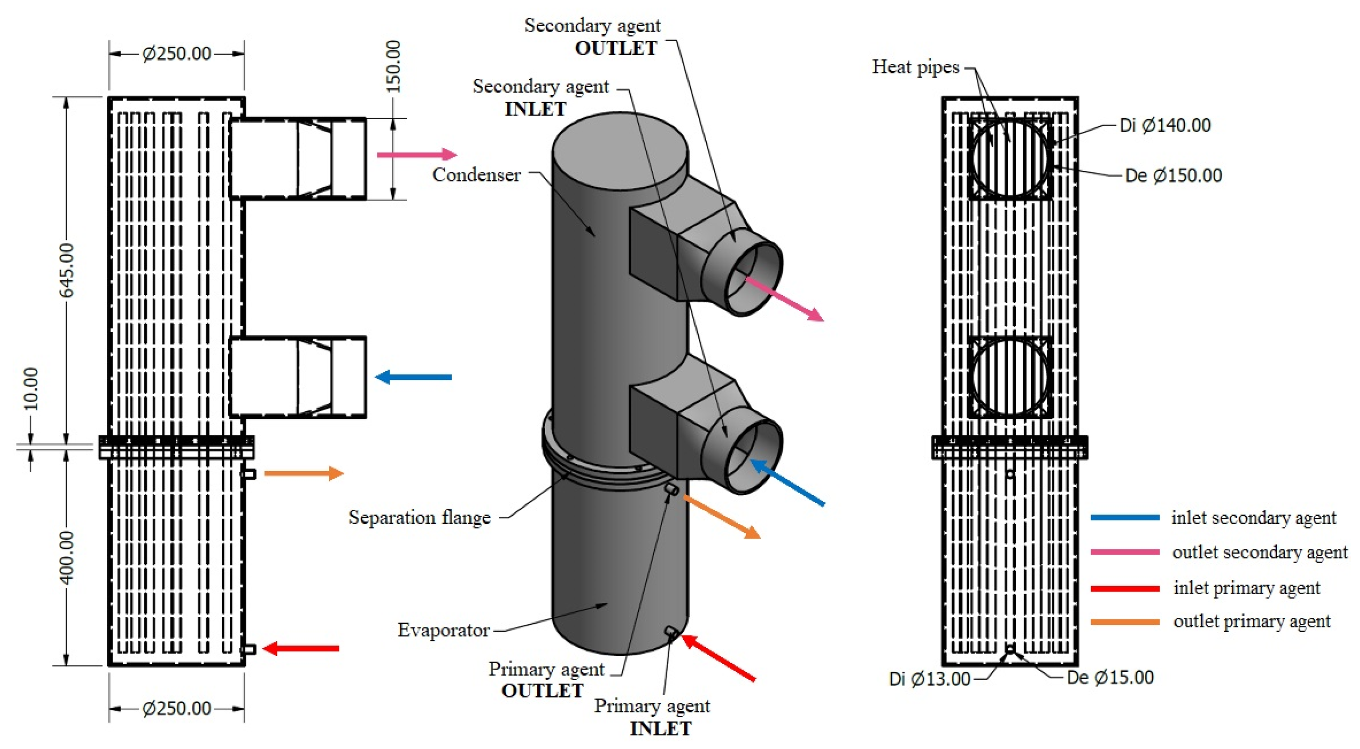
2.1. The Design of the Heat Pipe Heat Recovery System

The water-to-air heat recovery unit is purposefully designed to harness the thermal energy present in wastewater and effectively transfer it to a fresh air stream.
This equipment comprises two distinct zones: the evaporator and the condenser. To ensure complete segregation of the two fluid streams, a separating flange is strategically placed between the two zones, preventing cross-contamination. Inside the heat recovery unit, a set of fourteen vertically oriented heat pipes acts as a highly effective heat conductor, optimizing heat transfer from the heat source. The evaporator, condenser, and separation flange are made of stainless steel and the heat pipes are made of copper. Utilizing water as the working fluid, these gravitational heat pipes have been designed and optimized through extensive experimental testing [36]. Detailed construction specifications of the heat recovery unit can be found in Table 1.
The 3D model was designed using Autodesk Inventor 2021 software. A visual representation of the heat recovery system components described can be observed in Figure 1, providing a schematic overview.

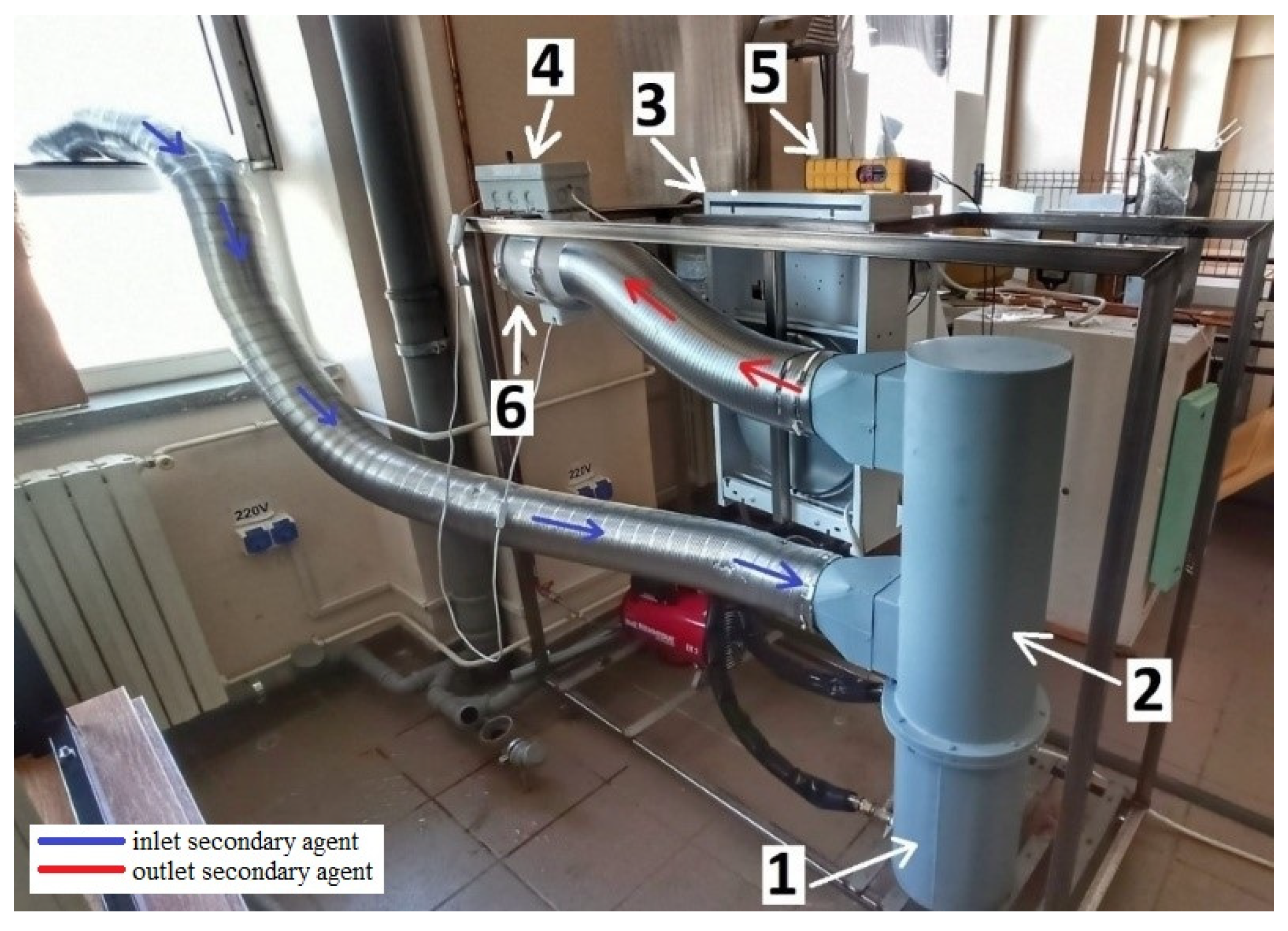
2.2. Experimental Setup

The water-to-air heat recovery unit has been constructed, and an experimental test stand has been established for precise testing and evaluation. The primary agent used in the experiment is hot water, generated by an 8-kW electric heating unit set to the required temperature for the experiment. To facilitate the flow of hot water, a pump is integrated into the electric heating unit, ensuring efficient circulation throughout the system. The primary circuit comprises thermally insulated stainless steel pipes with a diameter of 0.02 m, connecting the evaporator to the heating unit. For the secondary agent circuit, the air circuit, a stainless-steel pipe with a diameter of 0.125 m, is utilized, supported by a 9-speed fan to ensure optimal air circulation. The air velocity for each stage was measured using a digital anemometer, placed at the inlet of the condenser. The mean air velocity in the circular duct was determined using the Insize 9331-40 digital anemometer (Suzhou, China), which features an integrated function for calculating the average air velocity and has a precision of ±2%.
Given that the Insize 9331-40 digital anemometer’s impeller has a smaller diameter than the air duct, a potential error in measuring the average flow velocity was anticipated. To mitigate this, the anemometer was centrally positioned in the duct where the flow is most uniform, and additional measurements were taken at various points across the duct’s cross-section. The anemometer’s built-in averaging function, which records and averages the air velocity over time, was utilized to ensure accurate measurements. Furthermore, a correction factor based on the cross-sectional area difference between the duct and the impeller was applied to the recorded velocities. This approach, combined with the device’s precision, provided a reliable estimate of the average air velocity within the duct. The recorded values are presented in Table 2. The air inlet of the ductwork is located outside the building, allowing the air temperature to vary with atmospheric conditions. The temperatures were measured using an LT BTM-420SD electronic thermometer (Coopersburg, PA, USA), which has a precision of ±0.4%. The temperature sensors were strategically placed at the inlet and outlet of both the evaporator and the condenser to ensure accurate monitoring and data collection during the performance evaluation of the heat recovery system.
The equipment’s primary objective is to preheat or warm the air introduced into the building during cold periods, enhancing comfort and energy efficiency. For a visual representation, Figure 2 illustrates the detailed model of the experimental stand as currently present in the laboratory.

2.3. Tests Performed

In the following stage, the air-to-water heat exchanger was subjected to a comprehensive series of tests to evaluate its efficiency. The water temperature and velocity at the inlet of the evaporator were maintained constantly at 60 °C and 2.25 m/s, respectively. The air velocity at the condenser’s inlet is determined by the fan’s setting. Measurements were taken for two fan speeds, 3.5 m/s and 4.5 m/s, which have the corresponding cooling airflow rates of 207.1 m3/h and 268.6 m3/h, respectively. As the introduced air is drawn directly from the outside of the building, its temperature cannot be controlled. Each test lasted for 60 min, with the inlet temperature of the air fluctuating based on the outdoor air temperature. To facilitate analytical calculations and comparisons, an average temperature was calculated both at the inlet and outlet of the condenser. The fluctuation in average air temperatures at the equipment’s inlet are attributed to the tests being carried out on separate days. Table 2 provides an overview of these measurements.

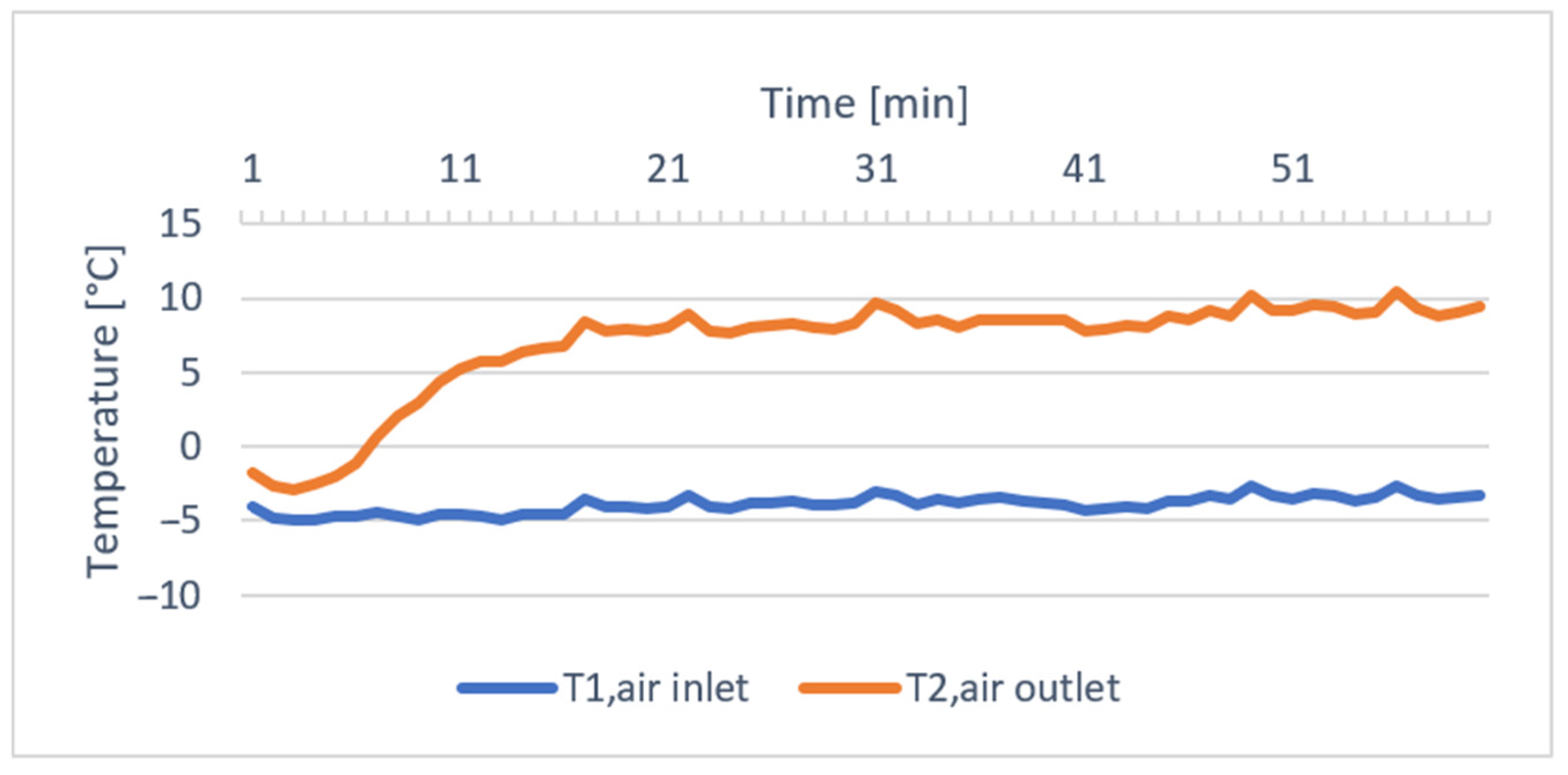
3. Results and Discussion

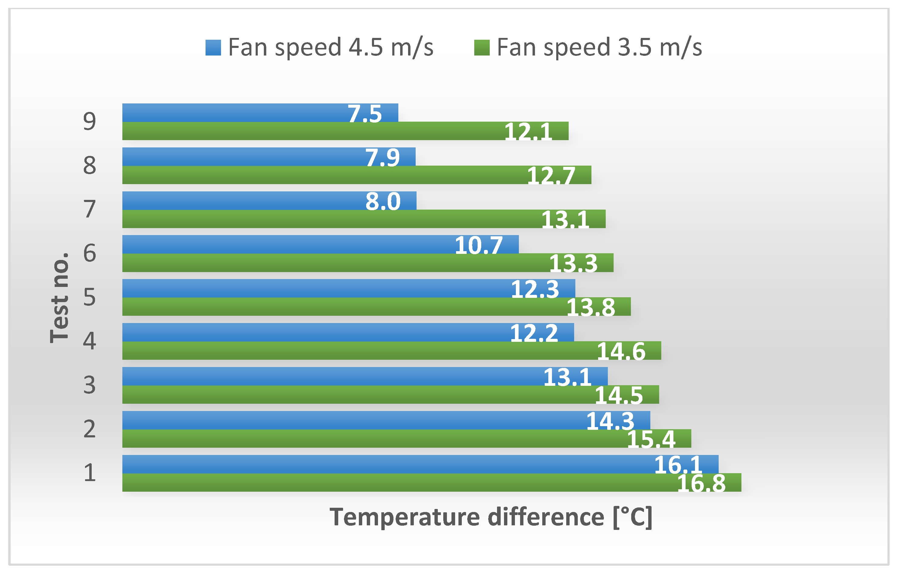
3.1. Experimental Results

A series of 18 experimental tests were carried out to investigate the performance and efficiency of the equipment under various conditions by manipulating the temperature and air velocity at the inlet of the condenser. The mean air temperature at the outlet of the evaporator was determined by calculating the arithmetic average of the sensor readings taken after the initial 15-min period, during which the temperature reached a stable state. The findings have been summarized and highlighted in Table 2. The temperature measurements presented in the following tables and figures have an associated error of ±0.4% due to the accuracy of the thermometer and ±1.5 °C due to the accuracy of the thermocouple.
To facilitate the visualization of air heating dynamics using the temperature acquired from the heat pipes, we calculated the temperature difference between the average air temperature at the condenser’s outlet and inlet. This analysis was conducted for both cases with air velocities of 3.5 m/s and 4.5 m/s, revealing that the difference in temperature between the inlet and outlet increases as the outdoor air temperature drops. These empirical findings have been presented graphically in Figure 3.

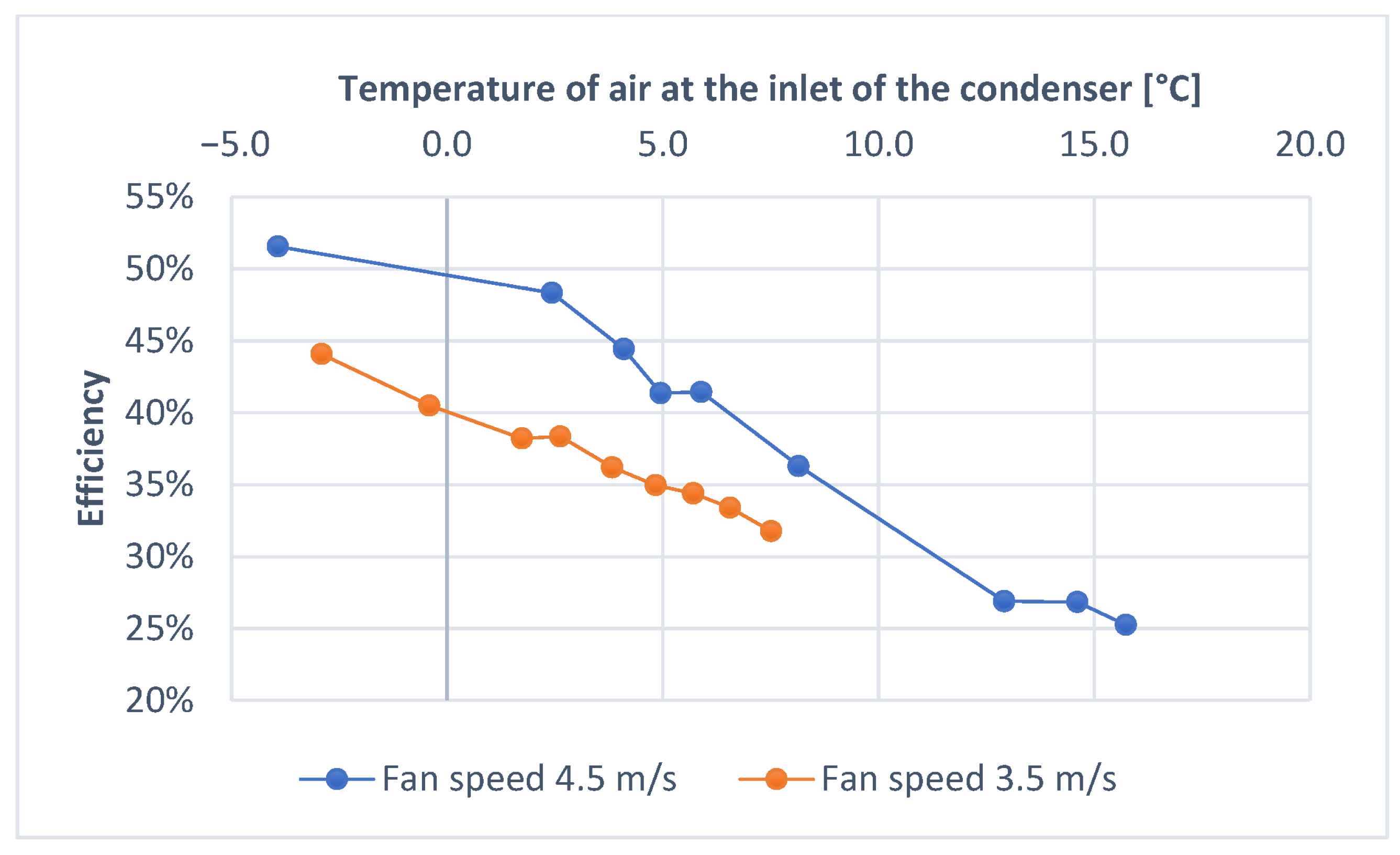
3.2. The Efficiency of the Equipment

In order to quantify the quantity of energy recovered by the heat pipes from the water and subsequently transmitted to the fresh air flow, the thermal heat flow rates were calculated for both the evaporator and condenser in accordance with Equation (1).
Q = C Ev ( T 2 , air T 1 , air ) = C Co ( T 2 , water T 1 , water )
Equation (2) offers an approach for determining the rate of heat transfer within the heat recovery system. The heat capacity rates for the evaporator (CEv) and the condenser section (CCo) can be established by multiplying the mass flow rate with the specific heat capacity related to the respective section. The efficiency of the equipment for each test is calculated through the use of Equation (3).
C Ev = Ev × c p , Ev
ε = Q Co Q Ev
The findings are presented in Figure 4. The influence of external air temperature on the heat exchanger’s efficiency is less pronounced at lower fan speeds compared to scenarios with higher air velocity. Notably, during tests 7, 8, and 9, it was observed that the effectiveness of the equipment drops to 25–27% when the external air temperature is higher, within the range of 13–15 °C.
Nevertheless, its peak efficiency is observed in the higher speed stage during test 1, where, at an external temperature of −3.92 °C, the condenser produced air at 12.23 °C, delivering an equivalent thermal power of 1553 W. Similarly, within the lower speed stage tests, the highest efficiency was also achieved during test 1, with an inlet air temperature of −2.91 °C, resulting in an outlet temperature of 13.86 °C and an equivalent thermal output of 1254 W.
Figure 5 illustrates the performance of the equipment under its most efficient scenario during test 1 when the fans speed is 4.5 m/s. T1,air inlet represents the temperature of the air at the inlet of the condenser while T2,air outlet represents the air temperature at the outlet of the condenser. It is notable that, after approximately 15 min, the air temperature at the outlet of the equipment reaches a state of stability, characterized by a constant value. Furthermore, the average temperature difference between the outlet and inlet remains at 12.23 °C.
In order to compare the results with the performance of other heat exchangers utilizing water as the primary agent and air as the secondary agent, the equipment’s overall heat transfer coefficient was calculated using Equation (4).
k = Q Co S × Δ t med
The average (mean) overall heat transfer coefficient has been determined for each specific scenario, generating values ranging from 39 to 61 W/m2 K. The average of these measurements was determined to be 49 W/m2 K, which is within the range of values reported in the existing literature for the overall heat transfer coefficient of water–air exchangers. These reported values typically range from 15 to 70 W/m2 K [37].

4. Conclusions

This study aimed to design and experimentally investigate a water-to-air heat recovery system utilizing heat pipe technology to harness waste heat from wastewater and transfer it to a fresh air stream. The research addressed the challenge of improving energy efficiency and reducing carbon emissions by leveraging low-grade thermal energy that would otherwise be wasted. Specifically, the research targets the need for efficient heat recovery solutions across residential, commercial, and industrial settings, focusing on the significant role buildings play in energy consumption and emissions. The heat recovery system developed in this study can be effectively applied in residential settings, where it can be coupled with solar thermal panels to preheat or heat incoming air, reducing the need for conventional heating and enhancing energy efficiency. In industrial settings, such as in steel and aluminum manufacturing, the system can recover waste heat from processes to produce preheated air for ventilation or other uses. This application not only improves energy efficiency but also reduces primary energy consumption and CO2 emissions.
The experimental setup involved a prototype heat recovery unit, which was rigorously tested under various conditions to evaluate its performance. The system’s efficiency varied between 25% and 51.6%, depending on the temperature and speed of the fresh air stream. The global heat transfer coefficient was determined to be 49 W/m2 K, aligning with values reported in the literature for similar systems.
The results demonstrate that the proposed heat recovery system is a viable solution for enhancing energy efficiency in HVAC systems and other industrial applications. By recovering waste heat and repurposing it for air heating, the system can contribute to significant energy savings and a reduction in CO2 emissions.
In conclusion, the study highlights the potential of heat pipe-based heat recovery systems in promoting sustainability across various sectors. While this study successfully demonstrates the system’s ability to achieve substantial temperature increases in the air, it primarily focused on validating the thermal efficiency of the heat recovery system. However, we acknowledge that other critical factors such as humidity, pressure, and air composition, which are essential for assessing overall air quality and system performance, were not considered in the current study.
Future research should build upon these findings by investigating the impact of the heat recovery system on additional air quality parameters. Exploring how the system affects humidity, pressure, and air composition will provide a more holistic understanding of its performance and suitability for various residential, commercial, and industrial applications. This expanded scope will help optimize the system further and ensure it meets broader environmental and operational standards, enhancing its applicability across different sectors.

Author Contributions

Conceptualization, Ș.E.V., A.B. and C.A.; methodology, Ș.E.V., R.Ș.V. and A.B.; software, M.C.B. and R.Ș.V.; validation, Ș.E.V., A.B., M.C.B. and N.E.K.; formal analysis, C.A. and Ș.E.V.; investigation, Ș.E.V., R.Ș.V., M.C.B. and N.E.K.; resources, M.C.B. and A.B.; data curation, R.Ș.V., C.A. and Ș.E.V.; writing—original draft preparation, Ș.E.V. and R.Ș.V.; writing—review and editing, A.B., C.A. and N.E.K.; visualization, Ș.E.V. and M.C.B.; supervision, C.A., A.B. and R.Ș.V. All authors have read and agreed to the published version of the manuscript.

Funding

This research received no external funding.

Institutional Review Board Statement

Not applicable.

Informed Consent Statement

Not applicable.

Data Availability Statement

The original contributions presented in the study are included in the article, further inquiries can be directed to the corresponding authors.

Conflicts of Interest

The authors declare no conflicts of interest.

Nomenclatures

HPHEHeat pipe heat exchanger
PCMPhase change material
T1,airAverage temperature of air at the inlet of the condenser [°C]
T2,airAverage temperature of air at the outlet of the condenser [°C]
QQuantity of heat [W]
CEvHeat capacity rate of the evaporator
CCoHeat capacity rate of the condenser
T1,waterAverage temperature of water at the inlet of the evaporator [°C]
T2,waterAverage temperature of water at the outlet of the evaporator [°C]
mEvMass flow rate of water [kg/h]
Cp,EvSpecific heat of water [kg/m3 K]
εEfficiency
kAverage (mean) overall heat transfer coefficient [W/m2 K]
SArea of heat exchange [m2]
Δ t med Logarithmic mean temperature difference [°C]

References

  1. IEA (International Energy Agency). Global Energy Review: CO2 Emissions in 2021; IEA: Paris, France, 2022. [Google Scholar]
  2. IEA (International Energy Agency). Net Zero by 2050; IEA: Paris, France, 2021. [Google Scholar]
  3. Firth, A.; Zhang, B.; Yang, A. Quantification of global waste heat and its environmental effects. Appl. Energy 2019, 235, 1314–1334. [Google Scholar] [CrossRef]
  4. Miró, L.; Brückner, S.; Cabeza, L.F. Mapping and discussing Industrial Waste Heat (IWH) potentials for different countries. Renew. Sustain. Energy Rev. 2015, 51, 847–855. [Google Scholar] [CrossRef]
  5. Kuah, C.T.; Koh, Q.Y.; Rajoo, S.; Wong, K.Y. Waste heat recovery research—A systematic bibliometric analysis (1991 to 2020). Environ. Sci. Pollut. Res. 2023, 30, 72074–72100. [Google Scholar] [CrossRef] [PubMed]
  6. Sreejith, K.; Varghese, B.; Das, D.; Devassy, D.; Harikrishnan, K.; Sharath, G.K. Design and Cost Optimization of Plate Heat Exchanger. Int. J. Adv. Eng. Res. Sci. 2014, 4, 43–48. [Google Scholar]
  7. Men, Y.; Liu, X.; Zhang, T. A review of boiler waste heat recovery technologies in the medium-low temperature range. Energy J. 2021, 237, 121560. [Google Scholar] [CrossRef]
  8. Xie, C.-Y.; Tao, H.-Z.; Li, W.; Cheng, J.-J. Numerical simulation and experimental investigation of heat pipe heat exchanger applied in residual heat removal system. Ann. Nucl. Energy 2019, 133, 568–579. [Google Scholar] [CrossRef]
  9. Jouhara, H.; Khordehgah, N.; Almahmoud, S.; Delpech, B.; Chauhan, A.; Tassou, S.A. Waste heat recovery technologies and applications. Therm. Sci. Eng. Prog. 2018, 6, 268–289. [Google Scholar] [CrossRef]
  10. Jouhara, H.; Almahmoud, S.; Brough, D.; Guichet, V.; Delpech, B.; Chauhan, A.; Ahmad, L.; Serey, N. Experimental and theoretical investigation of the performance of an air to water multi-pass heat pipe-based heat exchanger. Energy J. 2021, 219, 119624. [Google Scholar] [CrossRef]
  11. Hakim, I.I.; Sukarno, R.; Putra, N. Utilization of U-shaped finned heat pipe heat exchanger in energy-efficient HVAC systems. Therm. Sci. Eng. Prog. 2021, 25, 100984. [Google Scholar] [CrossRef]
  12. Mahajan, G.; Thompson, S.M.; Cho, H. Experimental characterization of an n-pentane oscillating heat pipe for waste heat recovery in ventilation systems. Heliyon 2018, 4, e00922. [Google Scholar] [CrossRef]
  13. Burlacu, A.; Sosoi, G.; Vizitiu, R.Ș.; Bărbuță, M.; Lăzărescu, C.D.; Ciocan, V.; Șerbănoiu, A.A. Energy efficient heat pipe heat exchanger for waste heat recovery in buildings. Procedia Manuf. 2018, 22, 714–721. [Google Scholar] [CrossRef]
  14. Wang, T.-Y.; Diao, Y.-H.; Zhu, T.-T.; Zhao, Y.-H.; Liu, J.; Wei, X.-Q. Thermal performance of solar air collection-storage system with phase change material based on flat micro-heat pipe arrays. Energy Convers. Manag. 2017, 142, 230–243. [Google Scholar] [CrossRef]
  15. Maraj, A.; Londo, A.; Gebremedhin, A.; Firat, C. Energy performance analysis of a forced circulation solar water heating system equipped with a heat pipe evacuated tube collector under the Mediterranean climate conditions. Renew. Energ. 2019, 140, 874–883. [Google Scholar] [CrossRef]
  16. Jouhara, H.; Almahmoud, S.; Chauhan, A.; Delpech, B.; Bianchi, G.; Tassou, S.A.; Llera, R.; Lago, F.; Arribas, J.J. Experimental and theoretical investigation of a flat heat pipe heat exchanger for waste heat recovery in the steel industry. Energy J. 2017, 141, 1928–1939. [Google Scholar] [CrossRef]
  17. Ma, H.; Yin, L.; Shen, X.; Lu, W.; Sun, Y.; Zhang, Y.; Deng, N. Experimental study on heat pipe assisted heat exchanger used for industrial waste heat recovery. Appl. Energy 2017, 169, 177–186. [Google Scholar] [CrossRef]
  18. Delpech, B.; Axcell, B.; Jouhara, H. Experimental investigation of a radiative heat pipe for waste heat recovery in a ceramics kiln. Energy J. 2019, 170, 636–651. [Google Scholar] [CrossRef]
  19. Jouhara, H.; Nieto, N.; Egilegor, B.; Zuazua, J.; González, E.; Yebra, I.; Igesias, A.; Delpech, B.; Almahmoud, S.; Brough, D.; et al. Waste heat recovery solution based on a heat pipe heat exchanger for the aluminium die casting industry. Energy J. 2023, 266, 126459. [Google Scholar] [CrossRef]
  20. Mathew, A.A.; Thangavel, V. A novel thermal energy storage integrated evacuated tube heat pipe solar dryer for agricultural products: Performance and economic evaluation. Renew. Energ. 2021, 179, 1674–1693. [Google Scholar] [CrossRef]
  21. Wang, Y.; Chen, Y.; Wang, K.; Li, X. Performance evaluation and thermal analysis of heat pipe flue gas waste heat utilization system. Energy Rep. 2022, 8, 210–217. [Google Scholar] [CrossRef]
  22. Alizadeh, A.; Ghadamian, H.; Aminy, M.; Hoseinzadeh, S.; Sahebi, H.K.; Sohani, A. An experimental investigation on using heat pipe heat exchanger to improve energy performance in gas city gate station. Energy J. 2022, 252, 123959. [Google Scholar] [CrossRef]
  23. Xue, L.; Ma, G.; Wang, L. Operation characteristics of air–air heat pipe inserted plate heat exchanger for heat recovery. Energy Build. 2019, 185, 66–75. [Google Scholar] [CrossRef]
  24. Egilegor, B.; Jouhara, H.; Zuazua, J.; Al-Mansour, F.; Plesnik, K.; Montorsi, L.; Manzini, L. ETEKINA: Analysis of the potential for waste heat recovery in three sectors: Aluminium low pressure die casting, steel sector and ceramic tiles manufacturing sector. Int. J. Thermofluid Sci. Technol. 2020, 1–2, 100002. [Google Scholar] [CrossRef]
  25. Jouhara, H.; Bertrand, D.; Axcell, B.; Montorsi, L.; Venturelli, M.; Almahmoud, S.; Milani, M.; Ahmad, L.; Chauhan, A. Investigation on a full-scale heat pipe heat exchanger in the ceramics. Energy J. 2021, 223, 120037. [Google Scholar] [CrossRef]
  26. Shafieian, A.; Khiadani, M.; Nosrati, A. Strategies to improve the thermal performance of heat pipe solar collectors in solar systems: A review. Energy Convers. Manag. 2019, 183, 307–331. [Google Scholar] [CrossRef]
  27. Ali, H.M. Applications of combined/hybrid use of heat pipe and phase change materials in energy storage and cooling systems: A recent review. J. Energy Storage 2019, 26, 100986. [Google Scholar] [CrossRef]
  28. Diao, Y.; Qi, N.; Wang, Z.; Zhao, Y.; Chen, C.; Wang, Z. Thermal performance analysis of a solar air collection–cascade storage system integrated with micro-heat pipe arrays. Sol. Energy 2021, 224, 1271–1290. [Google Scholar] [CrossRef]
  29. Rahim, N.C.; Remeli, M.F.; Singh, B.; Moria, H. Designing a Solar Heat Storage System using Heat Pipe and Phase-Change Material (PCM). Adv. Res. Fluid Mech. 2022, 91, 102–114. [Google Scholar] [CrossRef]
  30. Spriet, J.; McNabola, A. Decentralized drain water heat recovery: A probabilistic method for prediction of wastewater and heating system interaction. Energy Build. 2019, 183, 684–696. [Google Scholar] [CrossRef]
  31. Nagpal, H.; Spriet, J.; Murali, M.K.; McNabola, A. Heat Recovery from Wastewater—A Review of Available Resource. Water 2021, 13, 1274. [Google Scholar] [CrossRef]
  32. Hepbasli, A.; Biyik, E.; Ekren, O.; Gunerhan, H.; Araz, M. A key review of wastewater source heat pump (WWSHP) systems. Energy Convers. Manag. 2014, 88, 700–722. [Google Scholar] [CrossRef]
  33. Culha, O.; Gunerhan, H.; Biyik, E.; Ekren, O.; Hepbasli, A. Heat exchanger applications in wastewater source heat pumps for buildings: A key review. Energy Build. 2015, 104, 215–232. [Google Scholar] [CrossRef]
  34. Vizitiu, R.S.; Burlacu, A.; Abid, C.; Balan, M.C.; Vizitiu, S.E.; Branoaea, M.; Kaba, N.E. Investigating the Efficiency of a Heat Recovery–Storage System Using Heat Pipes and Phase Change Materials. Materials 2023, 16, 2382. [Google Scholar] [CrossRef] [PubMed]
  35. Mazhar, A.R.; Liu, S.; Shukla, A. A key review of non-industrial greywater heat harnessing. Energies 2018, 11, 386. [Google Scholar] [CrossRef]
  36. Vizitiu, R.S.; Burlacu, A.; Abid, C.; Serban, A.; Verdes, M.; Ciocan, V.; Branoaea, M. Experimental investigation on the optimum filling ratio of heat pipes used for heat recovery systems. In Proceedings of the International Conference Building Services and Energy Efficiency 2020, Iasi, Romania, 22–23 October 2020; pp. 154–161. [Google Scholar] [CrossRef]
  37. Available online: https://www.engineeringtoolbox.com/heat-transfer-coefficients-exchangers-d_450.html (accessed on 23 July 2024).
Figure 1. The 3D design of the HPHE.
Sustainability 16 07686 g001
Figure 2. The laboratory experimental stand: 1—Evaporator, 2—Condenser, 3—Electric heater, 4—Fan speed control switch, 5—LT BTM-420SD electronic thermometer, 6—Fan.
Sustainability 16 07686 g002
Figure 3. Temperature difference of air between outlet and inlet.
Sustainability 16 07686 g003
Figure 4. The efficiency of the heat recovery system.
Sustainability 16 07686 g004
Figure 5. Temperature variation of the air in the most efficient scenario.
Sustainability 16 07686 g005
Table 1. Constructive details of the components.
ComponentHeight [m]Diameter [m]
Evaporator0.4000.250
Condenser0.6450.250
Separation flange0.0100.300
Heat pipes1.0000.015
Diameter inlet/outlet primary agent-0.015
Diameter inlet/outlet secondary agent-0.150
Table 2. Average temperature of air at the inlet/outlet of the condenser.
Test No.Fan Speed 3.5 [m/s]Fan Speed 4.5 [m/s]
T1,air—Inlet [°C]T2,air—Outlet [°C]T1,air—Inlet [°C]T2,air—Outlet [°C]
Test 1−2.913.9−3.912.2
Test 2−0.415.02.416.7
Test 31.716.34.117.2
Test 42.617.25.017.2
Test 53.817.65.918.2
Test 64.818.18.218.9
Test 75.718.812.920.9
Test 86.619.314.622.6
Test 97.519.615.723.2
Disclaimer/Publisher’s Note: The statements, opinions and data contained in all publications are solely those of the individual author(s) and contributor(s) and not of MDPI and/or the editor(s). MDPI and/or the editor(s) disclaim responsibility for any injury to people or property resulting from any ideas, methods, instructions or products referred to in the content.

