Article

Integrating Design for Adaptability, Disassembly, and Reuse into Architectural Design Practice

1
Yeats Academy of Arts, Design & Architecture, Faculty of Engineering & Design, Atlantic Technical University, F91 YW50 Sligo, Ireland
2
School of Architecture, Planning and Environmental Policy, College of Engineering and Architecture, University College Dublin, D14 E099 Dublin, Ireland
*
Author to whom correspondence should be addressed.
Sustainability 2024, 16(17), 7771; https://doi.org/10.3390/su16177771
Submission received: 8 July 2024 / Revised: 14 August 2024 / Accepted: 22 August 2024 / Published: 6 September 2024
(This article belongs to the Section Waste and Recycling)

Abstract

:
Increased timber construction is putting pressure on Ireland’s limited structural-grade timber stock, while recovered timber is currently downcycled or incinerated. Design for Adaptability, disassembly and reuse (DfADR) has emerged as a response to this wasteful linear process, which can increase the life span of structures, the ease of disassembly during and after use, and improve the quality of recovered material. However, while many DfADR strategies have been identified, uptake in architectural practice is lacking. Impediments to DfADR were identified through an analysis of an existing timber-framed structure and a modified design developed based on the ISO 20887:2020 principles to illustrate practical solutions. In tandem, a decision tool was developed that organised the plethora of identified strategies by the ISO principles and the work stages used by designers to facilitate integration into practice. Modest reconfigurations of the space and roof structure increased adaptability, access to services for replacement and repair, and expansion potential to increase service life, while rationalized timber sizes improved reuse potential. Using wood nails in stud and joist framing, with screws replacing nails elsewhere, and omitting adhesives from the floor panels increased the ease of disassembly. These relatively minor changes resulted in nearly 3 times the amount of solid timber with a high reuse potential (≥2348 mm) recovered over the original design, highlighting the impact DfADR can have on the recoverability and reusability of timber.

1. Introduction

Residential buildings in Ireland have long been constructed of load-bearing masonry, with structural timber use limited to intermediate floor joists and roof structures. The growing phenomenon of timber platform framing in Ireland in the last 30 years has increased the share of this construction type to 27% of residential new builds, primarily using prefabricated wall and floor panels [1,2]. Despite this surge of interest in timber construction and demand for timber products, timber recovered as part of construction and demolition (C&D) in Ireland is typically downcycled into wood chip-based products or incinerated for energy [3].
Given Ireland’s limited structural-grade timber stock, the ever-increasing share of timber used in residential construction will put considerable pressure on timber supplies [4,5]. There is an opportunity to address this demand by sourcing timber from the waste generated during the demolition of the current and future building stock. Despite Ireland’s tradition of load-bearing masonry, an analysis of residential housing stock revealed that there is an average of 0.031 m3/m2 of timber that could be recovered from this source, with the predominant section size being 37.5 × 112.5 mm [6]. However, most buildings have not been designed to allow for the simple extraction of materials, resulting in unnecessary downcycling and premature disposal of potentially valuable demolition waste. An example of this is shown in Figure 1, where sections of good-quality roof timbers were removed from a building during demolition. Despite their substantial size (approximately 130 mm deep) and high reuse potential, these were not recovered.
To overcome this wasteful end-of-life process, considerable research in the past 30 years has postulated that buildings must be designed for adaptability, disassembly, and reuse (DfADR) to recover building materials for reuse [7,8,9,10,11,12,13,14,15,16,17,18,19,20,21,22,23,24,25]. Kibert’s early work on resource efficiency in construction [7] established the model on which later research would be positioned, identifying the 3-axis model of design stage, principles, and material resources. This was expanded by both Kibert and his colleagues [8,9,10] on Task Group 39 of the International Council for Research and Innovation in Building Construction (CIB), an international organisation which drew in the most noteworthy academics in the current field of DfD, including Crowther, Guy, and Durmisevic, to undertake further research on how this model could be achieved in practice. Contemporaneous research on cascades by Sirkin & Houten [11] and on timber by Fraanje in 1997 [12] reinforced the potential for this proposition, spawning separate but related research in the carbon storage potential of timber.
Though Sassi’s 2002 study [13] helped to position the research in a broader academic context, it was Crowther’s 2005 Design Guide [14] for the Royal Australian Institute of Architects (RAIA) that first introduced these ideas to a professional community of architects, elaborating on Kibert’s earlier 3-axis model. Much research has been done in this field since [15,16,17,18,19,20,21] including further design guidelines for professionals published by the UK-based Construction Industry Research and Information Association (CIRIA) [15], in Scotland [22] and the USA [23]. The most recent guidelines were derived from Durmisevic’s BAMB (Buildings as Material Banks) research project in 2019 [24]. Yet despite 30 years of research, in addition to the recent ISO 20887:2020 Sustainability in buildings and civil engineering works—Design for disassembly and adaptability—Principles, requirements and guidance [25], there has been limited uptake by the architectural community in practice.
The lack of engagement with DfADR principles by the architectural profession suggests assistance is required to integrate these concepts into practice [26]. While the extensive discussion of strategies and tactics for DfADR often refers to built examples [9,14,23,27], they are isolated with only limited attempts to implement this theoretical work on practical case studies. There have been considerable case studies on the disassembly of existing structures, most notably the work of the CIB Task Group 39 [8,9], which has contributed to the understanding of the impediments. Case studies to illustrate DfD implementation in design practice are rarer, such as Chisholm [17] and most recently Crowther [28], and tend to be idiosyncratic in nature and thus difficult to adopt systematically into practice. Some guidance documents suffer from this lack of system as well, though the Scottish Ecological Design Association (SEDA) [22] helpfully mapped these strategies to the Royal Institute of British Architects (RIBA) Plan of Work stages, a structure used by architects to organise their work-flow. And while the guidance document from the BAMB project [24] presents a system for interrogation, it is unwieldy for the practitioner to use effectively. An absence of material-specific guidance to aid practical implementation in the detailed design of buildings compounds this problem [6].
This lack of knowledge is worsened by a limited grasp of the theories that support DfADR, such as the time-dependent composition of the building’s structure, described by Brand as ‘layers of shear’ [29]. The evolving nature of construction technology also necessitates a continuously expanding knowledge base, which presents a significant challenge in integrating DfADR into the everyday workflow of designers [20,21]. Despite the growing expertise in architectural practice, turnover of staff may also pose difficulties by resulting in the loss of experience and skill [19].
The principal issues identified as impeding the adoption of DfADR in practice is the unsystematic nature of the guidance offered, which typically fails to address the workflow of practitioners; the potential loss of expertise given staff turnover; and the absence of material-specific guidance. To address these shortcomings the InFutUReWood (Innovative Design for the Future-Use and Reuse of Wood Building Components) research project developed the design tool, to both guide practitioners in their work and future-proof firms from the loss of expertise from staff turnover; an indicator system to assess their designs during design; and developed timber-specific guidance based on five case studies of residential housing types across Europe [30].
The current paper details the Irish case study, a typical semi-detached prefabricated house design, to identify the potential for reusing primary structural timber components. In doing so, the aim is to develop material-specific guidelines to aid the integration of DfADR into an architect’s design process. The analysis encompasses both the original design and a new modified design, based on the principles of Design for Adaptability (DfA), intended to extend the service life of the building, and design for disassembly and reuse (DfDR), which aims to maximise the recapture and reuse potential of structural timber. This study was developed in conjunction with creating the DfD Design Tool (Rev A), which aims to build knowledge and convey material-specific guidance to architects, further enabling the integration and awareness of circular economy thinking into everyday architectural practice.

2. Materials and Methods

The methods used in the study included a literature review to develop a comprehensive list of strategies identified in the research for DfADR, which were then reorganised in a more systematic manner to conform to the ISO 20887:2020 principles [25]. This was further developed through the study of a conventional timber-framed semi-detached housing structure, identified through a survey of recent timber-framed housing stock in Ireland, the methodology for which is outlined in Section 2.1. The reformatted guidance from the literature review was supplemented by the timber-specific knowledge gained from the case study analysis to develop the DfD Design Tool, which organised the guidance based on the conventional work stages used by practitioners and the ISO principles as outlined in Section 2.2.

2.1. The Case Study Method

The case study method, developed by our research consortium partners at RISE in Sweden, was vetted through interviews with researchers and industry partners within the InFutUReWood consortium and, following a trial of the method on the Swedish case study undertaken with the manufacturer, was validated on a further 4 case studies in the UK, Ireland, Spain, and a second case in Sweden [30]. LCA and LCC measurements, undertaken on a different work package to assess the first Swedish case study [31], were not used in the other case studies but instead, measures of estimated reusable timber that could be recovered were assessed as a means of verifying the usefulness of the identified changes.
A case study research method was chosen to allow detailed, in-depth, multi-faceted explorations of complex issues in real-life settings [32]. This method was deemed more suitable than other methods, as it would translate to other construction technology, lead to implementable results, enable ready comparison between different timber frame constructions and importantly be accessible to professionals. This approach allowed for quantitative data which supported the research and highlighted the value of integrating existing principles into practice. This particular study can be considered an instrumental case study, which uses a specific case to gain a broader appreciation of an issue [33]. This was undertaken in four steps [30]:
  • Step 0. Defining a scenario to design for
  • Step 1. Analysis of existing design
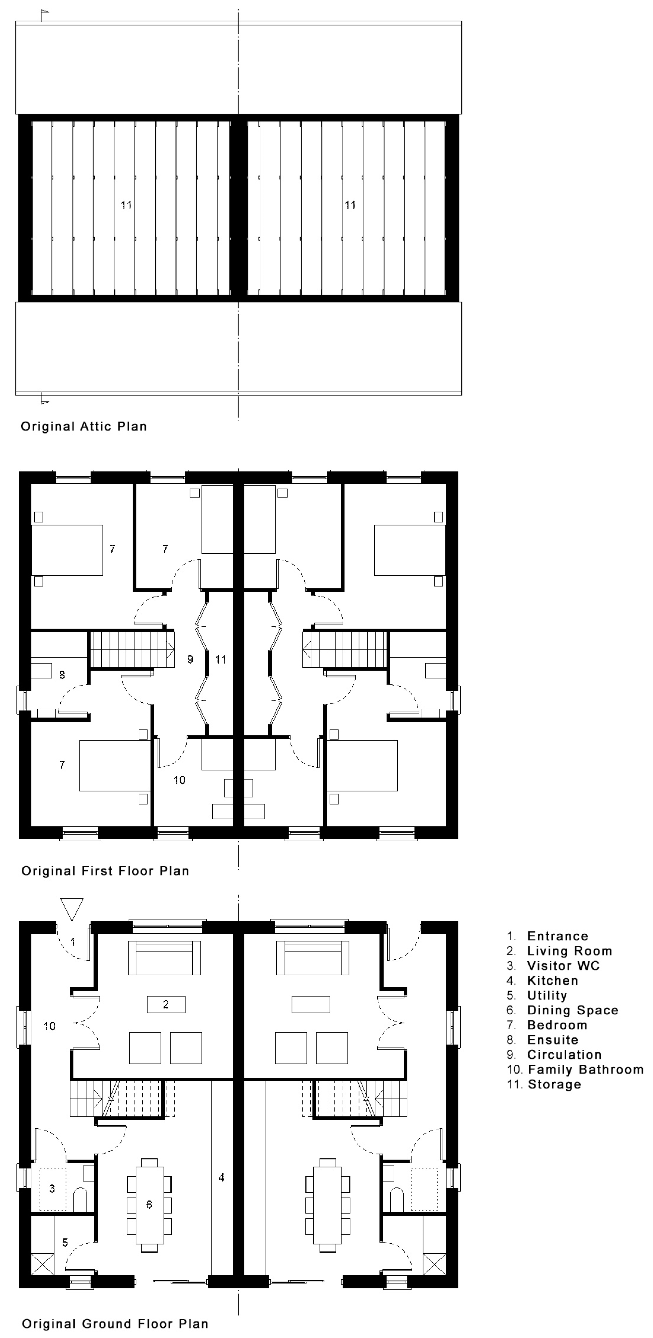
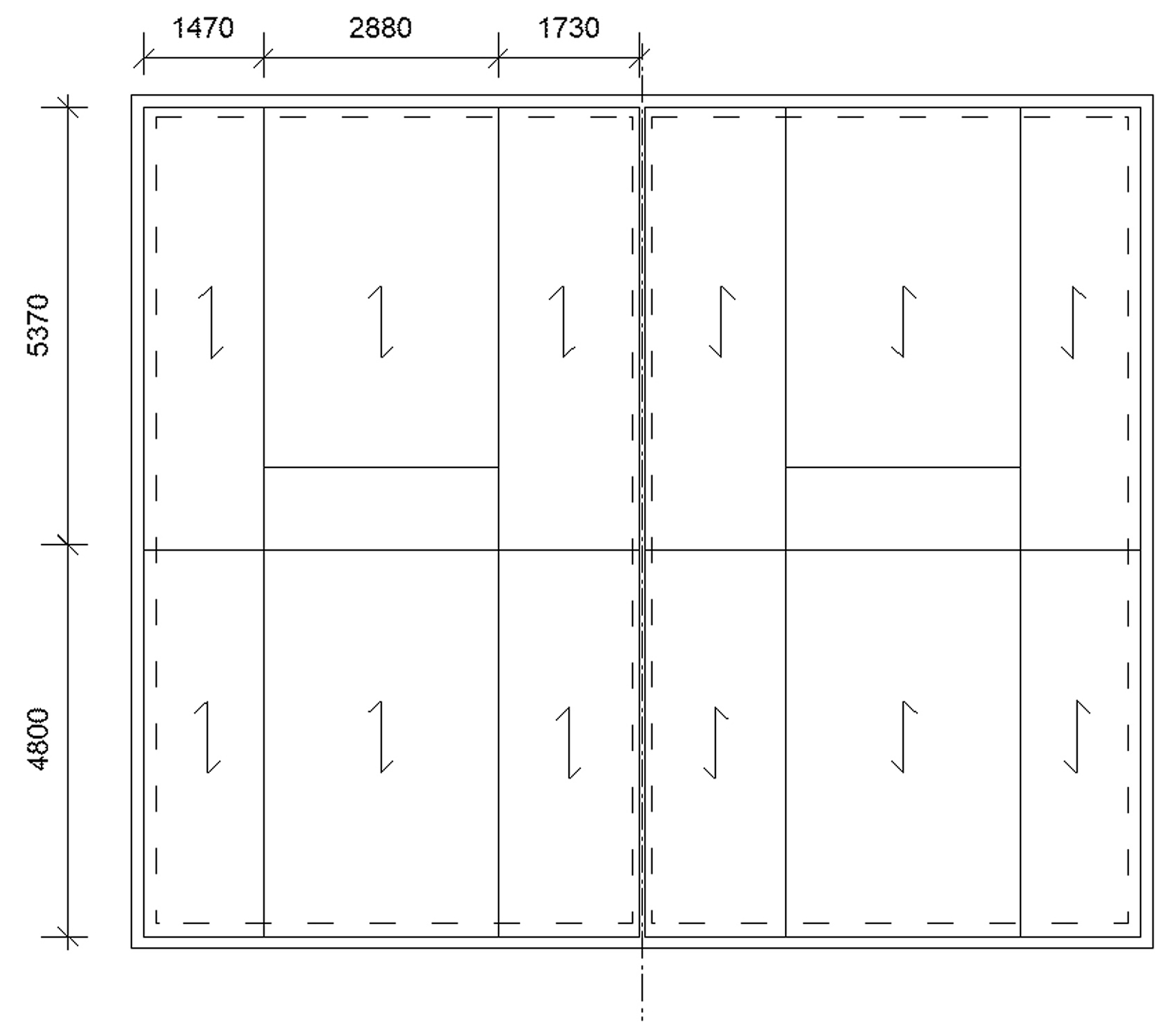
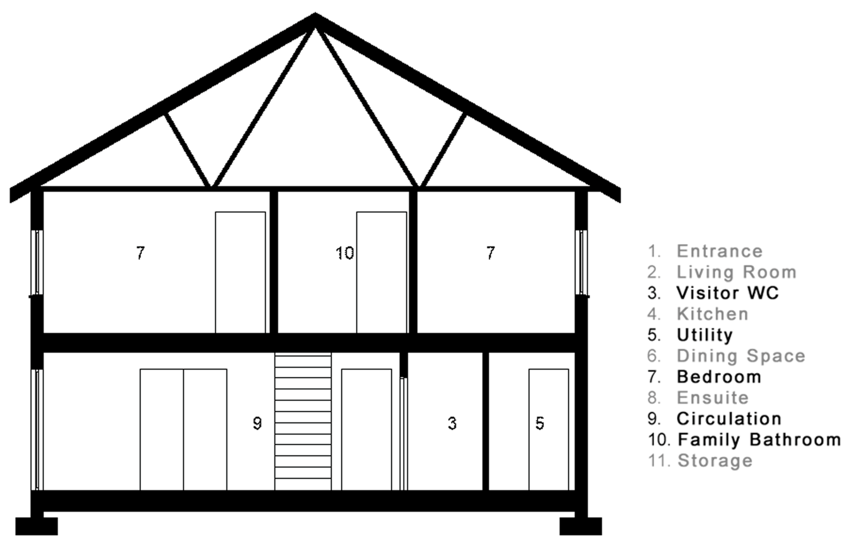
    • 1.1. Description of the building and how it is assembled
    • 1.2. Simulation of deconstruction and reassembly as well as identification of strengths and weaknesses
    • 1.3. Identification of areas to improve
    • 1.4. Selection of areas to improve
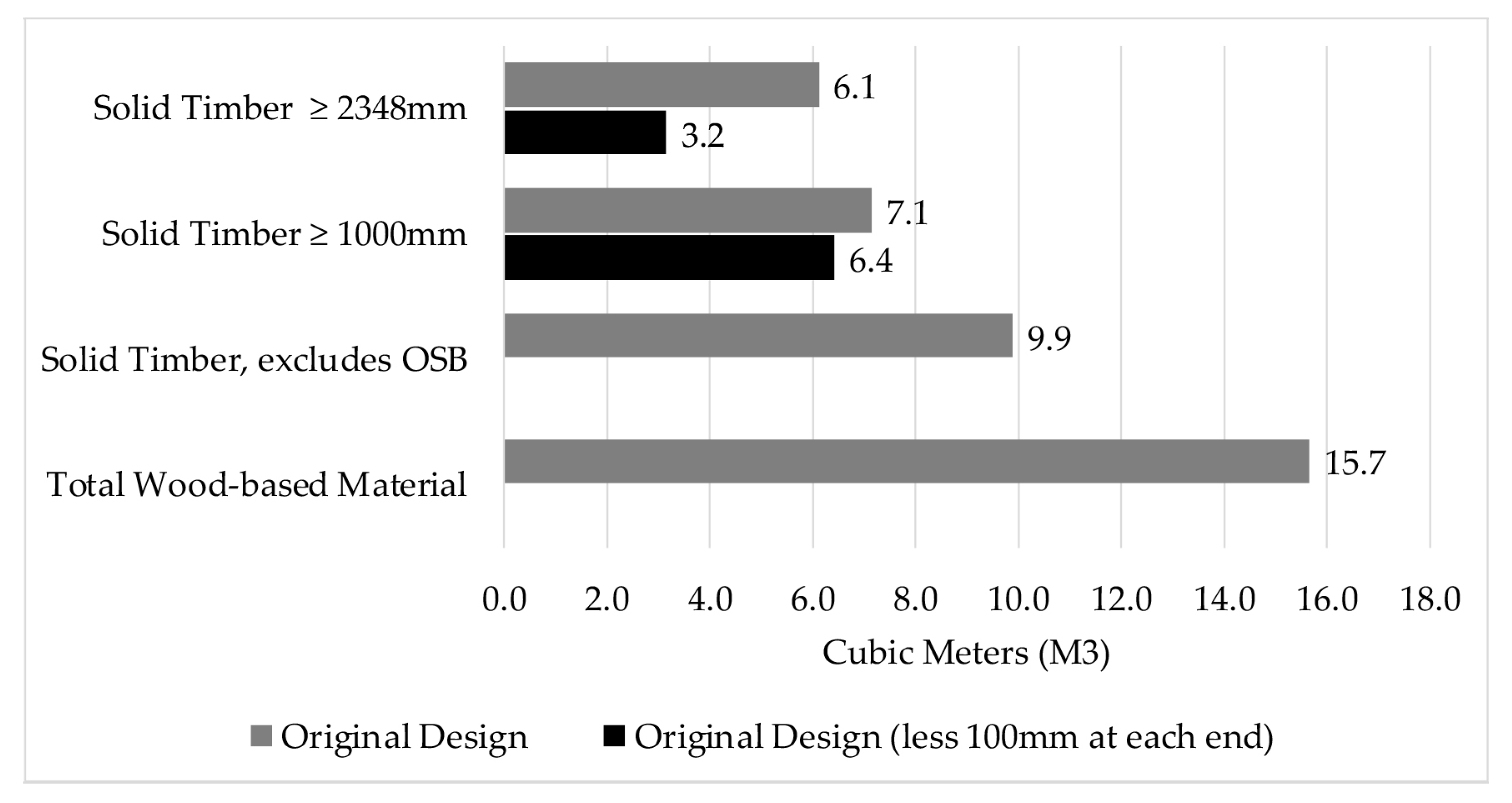
    • 1.5. Calculation of the amount of wood that can be reused with today’s design
  • Step 2. Modified design
    • 2.1. Design work
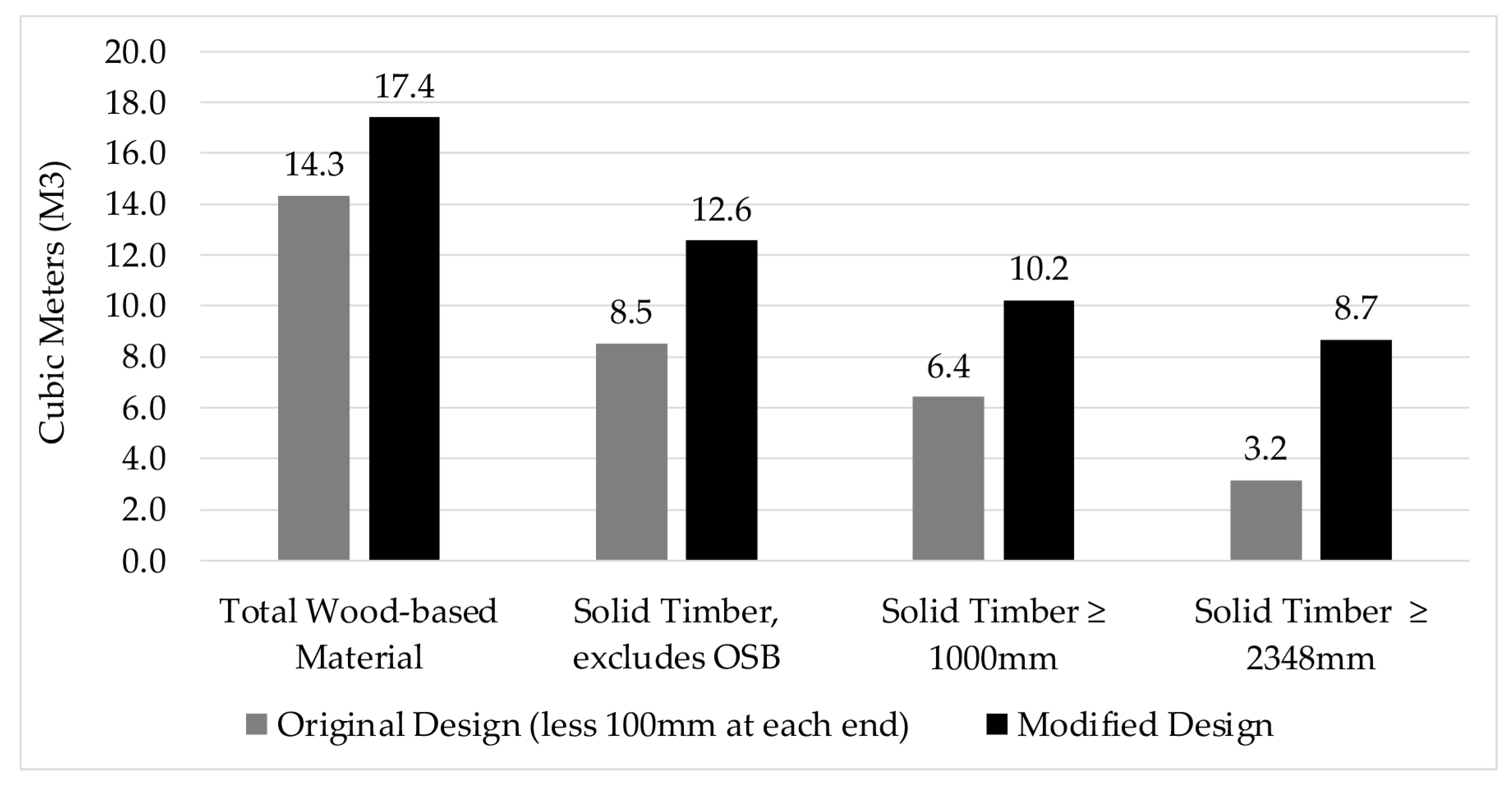
    • 2.2. Calculation of the amount of wood that can be reused with a modified design
  • Step 3. Comparison existing—modified design
  • Step 4. Guidelines for deconstruction and reuse
The guidelines developed in Step 4 in the case study structure formed the basis of a disassembly plan, which had often been discussed in the guidebooks [22,23] but never fully developed. The methodology was impacted by the expertise of the researchers involved in each case study. Thus, although all case studies involved a manufacturer in the analysis of potential ease of disassembly to varying degrees, only the Irish case study expanded the criteria used in the assessment to include adaptability, or DfA as it is termed in the ISO 20887:2020 [25], influenced by their architectural background.
The buildings used in the studies were selected based on being representative of the region’s housing traditions and construction methods. The Irish case study was sourced from an Irish timber frame company, Cygnum Timber Frame. Following the definition of the Case Study and Reuse Scenario, each structural timber element (linear and planar) was modelled in 3D using Vectorworks BIM (2021 SP5 (64 Bit)) to generate detailed material schedules. The material schedules were transferred to Microsoft Excel 365 for verification of data and volume calculations and formatting. With this information, the original design was analysed to determine how successfully it could be disassembled in the chosen reuse scenario. The practical challenges to DfADR in the design and assembly of timber-framed dwellings were investigated through engagement with the timber-frame company responsible for the original design. The anticipated recovery rate of timber material from the original design was calculated using the information from this interview in tandem with the material inventory. The challenges to disassembly identified in the original design were assessed to establish how these barriers might be removed. Utilising the DfA and DfD principles set out in ISO 20887:2020 [25], a modified design was developed and modelled by amending a copy of the original BIM model. This process allowed for a comparison of projected recovery rates between both designs. Finally, the modified design was further developed to replace the current concrete ground slab with a suspended timber-framed floor.

2.2. Design Tool to Aid Implementation of DfADR

In parallel to the case study analysis, a qualitative tool to guide design decisions was developed to aid designers in implementing DfD in their workflows, as only about 2% of practices design for disassembly as a common practice [26]. The tool was developed in Microsoft Excel and based on an expanding grid format. Two axes represent the project work stage (Timescale) and the DfD principles to be implemented (Action), respectively (Figure 2).
To provide a common framework for progressing building projects from inception to (post) completion, professional bodies for both engineers and architects publish work-stage flow documents. These documents aim to organize the process of briefing, designing, constructing, and operating building projects into stages and such an organisation was deemed suitable for the tool’s structure. The Royal Institute of British Architects (RIBA) produces one such work plan, and this was chosen because it is well-established in the industry and has international recognition. The DfD principles defined in the ISO 20887:2020 [25] were used as a framework to organize the varying strategies and tactics sourced from a range of other guidance documents [10,15,18,22,23,27,34] and augmented with the authors experience as practicing architects. The ISO principles were chosen as they are internationally applicable and may benefit from revision and be upgraded over time. The ISO principles are applicable to all types of buildings, as well as their constituent parts, and used for new construction, refurbishment and renovation [25]. The specific principles used in the tool, which covered only the DfD principles and did not extend to DfA, included the following:
  • Allow for safe deconstruction
  • Supporting re-use (Circular Economy Business Models)
  • Standardisation
  • Ease of access to components and services
  • Simplicity
  • Independence/reversible connections
The final five DfD principles in addition to adaptability are used to signpost the discussion in the Results. The tool and its structure were shared and discussed with professional architectural and engineering associations in Ireland and the UK (RIBA, RIAI, IStructE) during development to ensure its suitability and value. The tool was then validated within the Irish case study [30] as well as in a third-level DfADR module at University College Dublin, where it was found to successfully assist student designers in implementing DfD principles. The case study further developed the tool, particularly integrating material-specific tactics [6]. The DfD Design Tool (Rev A) is available at a link provided at the end of this paper under Data Availabilty Statement.

2.3. Limitations

While every effort was made to transpose the original 2D design drawings to BIM, not all information on the original design was provided by Cygnum Timber Frame, and as a result, certain minor aspects of the original design were unclear. Where this was the case, best industry practice was assumed when completing the model [35]. The review focused on timber products installed or supplied by the timber frame company, and while non-structural elements such as timber battens were included, the primary focus of the study was the structural timber elements. As a result, many other timber-based materials, such as doors and windows, architraves, skirtings, stairs and fitted furniture, were not included in the analysis.

2.4. Assumptions

Certain assumptions were made when assessing the quantity and quality of timber recoverable from the original and modified designs.
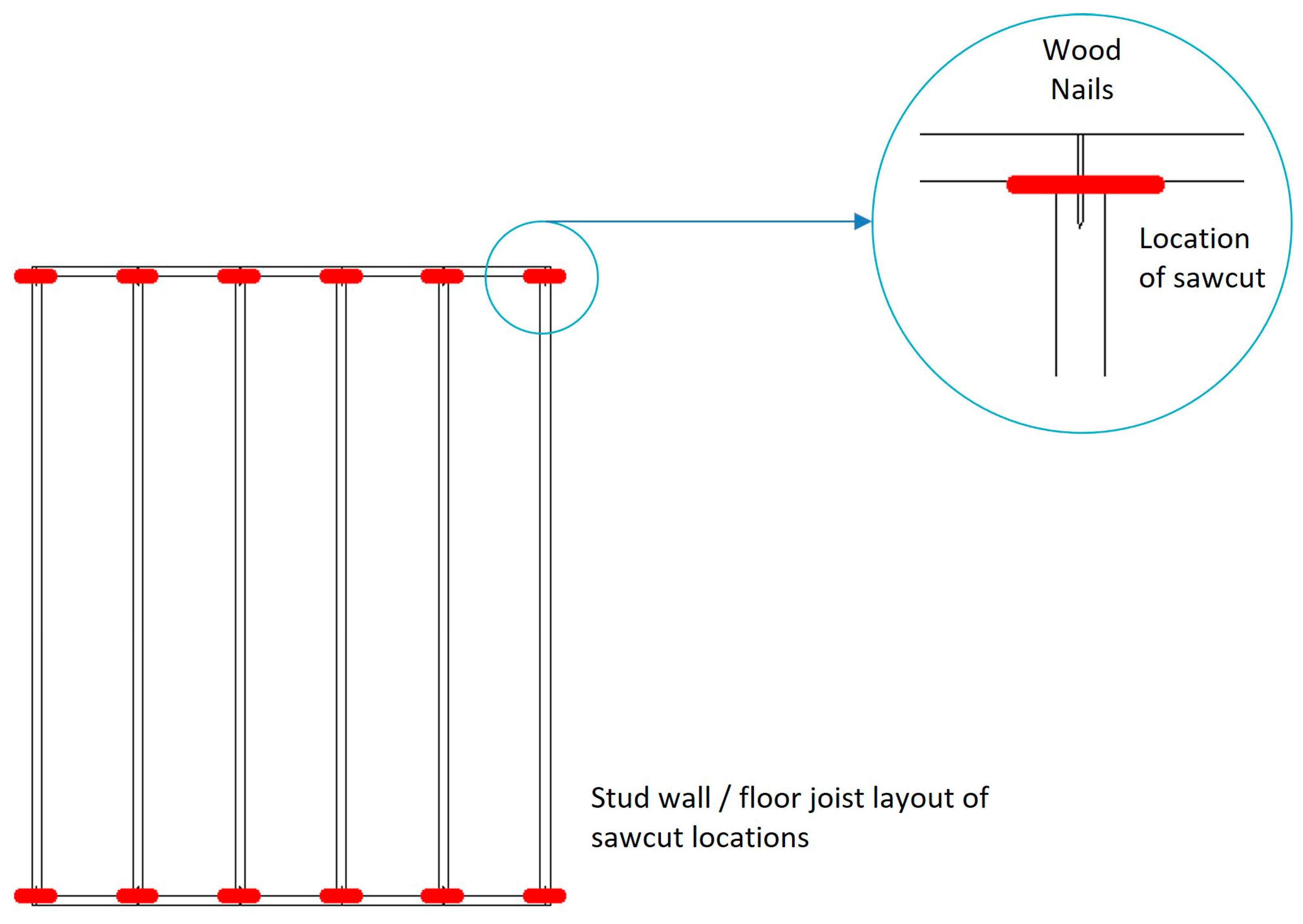
  • A 100 mm portion will be removed from both ends of each timber element in the original design to reduce the risk of nails remaining in elements or honeycombing. Honeycombing occurs at the end of elements when nails are removed, which makes the secure reinsertion of nails into solid material in a new build problematic. This is discussed in greater detail in the Results. Less material could be removed if the exact size of the nail used was known but, as this knowledge is unlikely on a demolition site, 100 mm ensures the ends will be free of honeycombing.
  • Timber lengths less than 1000 mm would have limited opportunities for reuse. These lengths would suffer from honeycombing resulting in 100 mm being taken off each end, rendering them unsuitable for their original use, such as blocking in studs and joists.
  • A length of 2348 mm is considered a benchmark in defining the quality of recovered timber, as it was the stud length used in the original design so represents the industry standard. A stud of this length will permit an overall floor-to-ceiling height above 2400 mm (38 mm sole plate + 38 rail + 2348 mm stud + 38 mm top rail + 38 mm binder). The absolute minimum stud length to achieve a floor-to-ceiling height of 2400 mm, accounting for plasterboard ceiling and thin laminate floor as finishes, would be 2280 mm. However, this does not allow for construction tolerances or the possibility of a different floor or ceiling system.
Some materials were not considered suitable for reuse and were omitted from the recovery rate calculations. These include:
  • External and internal wall battens have been omitted due to the small section size, frequency of penetrations, original low value, and the likelihood of breakage during removal.
  • Sole plates are not considered suitable for reuse because of the likely degradation due to their location and the considerable number of penetrations.
  • Oriented Strand Board (OSB) sheets, and composite materials containing OSB, due to the unknown service life and difficult recovery without damage.

3. Results

3.1. Reuse Scenario

A critical early step in the analysis was establishing the anticipated reuse scenario that would impact the material being recovered in the future and frame the analysis. The original house design is constructed using prefabricated 2D wall and floor panels. It could, therefore, have been analysed under a scenario where these panels were reused, made possible simply by using screws instead of nails, as was done in other case studies in the InFutUReWood Project (UK, Sweden) [30].
The advantage of recovering large modules for direct reuse is the reduction in the time and energy needed for deconstruction and the reduction in the risk of damage [30]. However, there were disadvantages identified in the Swedish and UK studies, including the complexity of the modules and their interconnected configurations [30], which would mean any future design would be required to ‘work around’ these units, potentially limiting the demand and reducing the likelihood of reuse [36]. Other issues identified in these studies were the many irreversible or hidden connections, the inaccessibility of services, the interconnected layers of the structural modules and many different component sizes, all of which could be redressed [30]. The direct reuse of floor and wall panels could be further complicated by potential local design factors, such as changes in the climate or in building regulations, which might impact any future design. By comparison, reducing these modules to individual materials such as a stud or joist allows for a more agile design in the future, not limited by local design factors, and less affected by changes in specification such as U-value or airtightness requirements.
The future scenario chosen for the Irish case study therefore considered the disassembly process from the perspective of the ultimate ‘end-of-service-life’ (50 years+) of the panels to complement the UK and Swedish case studies, when the panels would be disassembled into the individual material components, such as studs and joists, transported to a merchant or another building site, and reused in construction for the same or similar purpose. This approach would support the circular marketplace, which is considered a fundamental principle by ISO 20887:2020 [25].

3.2. Analysis of the Current Design

The case study house is semi-detached, sharing a party wall with a mirrored property (Figure 3). This semi-detached condition is prevalent in Ireland, accounting for almost 30% of dwellings [37] accommodating over 50% of the Irish population [38]. The house has two floors: the living room, kitchen, utility, and visitor’s toilet are located on the ground floor with three bedrooms, a family bathroom, a wardrobe, and general storage on the first floor (Figure 3).

3.2.1. Adaptability Assessment of Original Design

The dwelling is entered from the front, marked by the arrow in the drawing (Figure 3), with an entrance hall running to the rear providing access to the living room, stairs, kitchen, and visitors toilet. The entrance hall accounts for almost 25% of the ground floor area, which is noteworthy. The layout of the internal walls at the first-floor level does not align with those at the ground-floor level. However, the first-floor bathroom is located over the location for the kitchen which suggests that services may be rationalised. It does however result in the ground floor toilet being misaligned from the vertical plumbing services. The floor cassettes at the first-floor level, and the roof structure, are supported by the front and rear walls, making these the principal load-bearing walls, reducing the opportunity for extension or expansion (Figure 4).
The roof volume is formed using fink trusses at 400 mm centres (Figure 5). The trusses are composed of small section timber members (38 × 89 mm), aligned in-plane, and connected using mending plates. Nailed truss clips connect each roof truss to the head binder of the external walls, while bracing is nailed across the trusses to provide lateral stability. This configuration of trusses does not allow for inhabitation of the roof space without significant structural modifications.
The ISO 208870:2020 principles for DfA suggest that buildings should be: versatile, meaning that new patterns of use should be possible with little change; convertible, meaning non-structural changes can be made easily to accommodate a change in use; and expandable, meaning the ability to easily expand the building vertically or horizontally [25]. The partial rationalisation of the vertical plumbing runs both improves accessibility, a DfD principle, but also allows for the potential to reconceive the upstairs living space as an independent unit. This latter potential for convertibility is strengthened by the fact that none of the interior walls are load bearing. Despite its excessive use of space, the entrance hallway could be understood to support this convertibility potential. However, the excessive use of space for the entrance likely reduces the short-term versatility of the space and compromises the effective use of space available. The load-bearing nature of the front and rear walls of the house, while not excluding the potential to expand horizontally, does compromise this principle by requiring significant structural changes to achieve. The use of the fink truss likewise effectively denies the opportunity to expand the occupied space into the attic.

3.2.2. Disassembly Assessment of Original Design

The ground floor is a concrete slab on grade and as the study was examining the recovery of structural timber this material was considered C&D waste. The first-floor cassettes consist of tongued and grooved OSB sub-floor glued and then nailed at 150 mm centres to 300 mm I-joists (Figure 6). These units are manufactured off-site and craned into position as large, prefabricated elements, as are the wall panels. The timber frame company which was responsible for the original design noted that they would not reuse I-joists in a second application [39,40]. The study has, therefore, assumed that it will not be possible or desirable to reuse OSB or components containing OSB in the future due to its lack of robustness and uncertainty of service life. However, even if one would accept I-joists for a second use, as was done in the other case studies [30], the presence of the glue, particularly where it binds two floor cassettes together, makes the extraction process of the cassette, as well as each I-joist, without damage improbable. This was addressed by eliminating the glue at the cassette joint in the Swedish case study [30].
As discussed previously, the roof trusses are composed of small section timber members (38 × 89 mm) connected with mending plates. The smaller members used for bracing the trusses are assumed to be unrecoverable given their dimension and frequent nail fittings, which would likely lead to substantial damage at demolition. The small section truss members would also suffer damage on the removal of the mending plates, as discussed by Chisholm [17]. Given that their dimension lends itself to use in a truss rather than any other structural member, the most likely scenario is to retain the trusses intact for reuse. However, as this case study’s intention was to estimate the recoverable timber as base elements, the trusses were assumed to be disassembled for reuse or recycling.
The most significant solid timber structural element in the houses were the wall studs, delivered as 2D composite wall panels, which included 38 × 140 mm studs, insulation, vapour control layer and OSB3 facings. A service cavity is also nailed to the panels, though these battens were also considered unrecoverable. The party wall between the houses is a double 38 × 89 mm stud wall clad with OSB3 on each side of the frame. These elements come pre-clad with plasterboard to ensure their fire integrity. Panel to panel connections are toe-nailed from the interior at maximum 300 mm centres vertically, then sealed with tape. Panels at ground level are fixed with nails to the sole plate at 600 mm centres, which in turn is anchored to the concrete slab with Rawlplug screws. Given the number of penetrations in the ground floor sole plate and its potential degradation based on its location, this was deemed unrecoverable. The first-floor walls are nailed at 600 mm centres to the sole or framing plate nailed to the floor cassettes.
Nails were used exclusively in the construction and are considered difficult to remove [17,22,23], particularly those installed using a nail gun, which uses a force that tends to embed the nail deeply into the substrate. This increases the cost of deconstruction and poses further challenges to successfully reusing timber, as there is a risk that not all nails are removed [41]. For nail fittings between wall panels or from wall to plate, if they cannot be mechanically extracted it is assumed they would be saw cut. The remaining metal in the stud work from these fittings, in addition to the miscellaneous fittings applied for services or finishes, would not compromise the structural reuse integrity of the stud. More critical to the reuse of studs are the fixing methods used in framing the walls.
The fixing method in the original design for a timber stud is from beneath and above, through a bottom and top rail using metal nail connections [39]. When a 140 mm stud is used, three nail fixings at each end are required, while a 90 mm stud requires two nail fixings at each end. In modern off-site timber frame construction, nails are commonly installed using mechanised pneumatic force, either by a hand-held nail gun or an automated nailing station. If the redundant fixings are removed from the timber, the remaining holes caused by the penetration result in a honeycombing effect, reducing the element’s potential reusability due to the difficulty of securing new fittings into the substrate. Alternatively, the ends may be removed to address the honeycombing or any remaining mechanical connections, but this reduces the potential reuse of the timber element, particularly in the case of studs which may no longer have sufficient length to be directly reused. In this analysis we assumed that 100 mm was cut from each end of the studs. The analysis of the original design identified that timber framed wall panels contain a significant quantity of elements longer than 2348 mm before trimming, largely consisting of timber studs and roof members, which totalled approximately 6.1 cubic meters (Table 1). This equates to 62% of the structure’s solid timber and would be considered highly reusable if the difficult problem of honeycombing could be overcome. Unfortunately, the recovery volume drops to 3.2 cubic meters once the trimming is factored in, reducing the rate of recovery to 32% of all solid timber, or 39% of solid timber deemed recoverable (Table 1).

3.3. Modified Design

Using the DfD design tool, coupled with lessons derived from the analysis of the original design, a modified design was developed to better address the principles for adaptability and disassembly. The fundamental principles of ISO 20887:2020 [25] are used to organise the discussion of the reconfiguration of the dwelling (Figure 7) and the modifications of its technical details to achieve these aims.
Much of the research to date on connection details has been theoretical, with limited examples examining technical implementation. There has been innovative research into frame construction that have adapted the technology significantly, proposing plywood frames systems with friction fitted half-lap joints or small modularized timber frame systems with bolted connections [42]. However, changing the framing technique or material would require substantial adaptation of existing supply chains, industrialised fabrication processes, and on-site construction practices, reducing the likelihood of implementation. Light timber frame (LTF) construction utilises timber’s natural structural properties and inherent workability; therefore, reconsidering the material for framing may not be desirable, particularly if the material has a greater environmental impact such as the plywood-based proposals [42]. The modular timber frame system with bolted connections was rightly identified by the authors as significantly more expensive [42], also reducing the likelihood of uptake within the construction industry. Even smaller adjustments proposed to LTF panel systems to include complex bolted connections [17] may be difficult to adopt in practice. The approach taken in this case study was to identify the solutions that could be readily adopted into current construction practice, with limited impact on costs, to optimise the potential for early implementation [43].

3.4. Adaptability

As discussed earlier, greater versatility, convertibility, and expandability are considered principles of adaptability [25]. By making a range of changes to the spatial layout of the house, including the relocation of the entrance door and reconfiguration of the first-floor internal walls, more flexible spaces are created (Figure 7). The entrance layout in the original design resulted in approximately 25% of the ground floor being used for circulation purposes, such as hallways and stairs, while the adapted design recovers much of this space for occupation providing potential for a home workspace.
The upper floor is arranged for future-proofed access to the attic with the location for a future stair marked as 12 in the plan, which can be used for storage, while a cut-truss roof structure replaces the engineered fink truss to enable conversion to living space at a future date (Figure 8). While a roof structure framed on-site would increase both labour and material costs as well as adding time to the construction, an alternative approach would be to use a prefabricated attic truss. This would address future occupations while eliminating additional labour costs and time by conforming with current industry standards of construction. A reorientation of first-floor joists (see Section 3.8) allows for subsequent ease of extension by changing the primary load-bearing walls from the front and rear to the party wall and gable walls, thus removing the need for an additional beam.
The occupation of this roof space could be further enhanced by increasing the roof pitch; however, deeper timber sections are required for the attic truss (or a cut truss roof), which could increase the cost, so was not proposed. Nevertheless, deeper sections would offer increased reusability of the timber members and the additional depth necessary to accommodate insulation to ensure thermal comfort in an attic conversion. This added adaptability and flexibility increase the potential lifespan of the building while also improving material efficiency and the reuse potential of the materials recovered in the future.

3.5. Supporting Re-Use

I-joists, which are used in the original design, have a high OSB content, which, due to concerns about their service life [39,40] could restrict their reuse. In the modified design, these elements are replaced with solid timber joists, which should prove more reusable in the future due to increased robustness and a more comprehensive range of uses [10]. This alteration may also impact the cost of the construction, and while the research project did not include a full material costing, a more limited search for retail prices in Ireland revealed that solid timber joists are quite competitive with OSB-based I-joists.

3.6. Ease of Access to Components and Services

Internal linings and mechanical & electrical services have a higher rate of change than other parts of a building [10,29], such as the structure, and therefore ease of access to components and services is considered a fundamental principle of DfADR [15,22,43,44].
Routes for electrical services in the current design are often cored on-site by follow-on trades through internal load-bearing walls and I-joists as necessary to allow wires to be pulled through [35]. This complicates access for future repairs and results in considerable additional holes and metal attachments added to structural members, which can complicate reuse. Irish regulations also require a fire-rated assembly, which means that plasterboard must be used on all internal surfaces, creating difficulty in accessing services within a wall cavity without incurring damage.
The revised design uses two tactics to address this issue. Mechanical services are rationalised and positioned to create vertical service zones, relocating the bathrooms to take advantage of these centralised services, making it easier to maintain and upgrade without creating too many openings in the external airtight layer. This new organisation will also make disassembly simpler. The service zones are located to provide ease of access in the future (highlighted in blue in Figure 7). The further inclusion of a suspended timber floor at the ground floor level, instead of the concrete slab, would also increase opportunities for flexibility in accessing services. This is complemented by adding removable linings in front of the required plasterboard, operated with either hinges or a French cleat system created (Figure 9) in which services can be run when required [45].

3.7. Avoidance of Unnecessary Treatments & Finishes

The Irish standard I.S. 440 Timber Frame Construction, Dwellings and other Buildings dictates that several timber components, including studs, top and bottom rails, and sole plates, should be treated with preservative [46]. Otherwise, timber should be specified that has natural durability or be treated with a preservative appropriate to their end use and/or the Use Class listed in the building specification [47]. Existing research by the Waste and Resources Action Programme (WRAP) has found that 85% of wood from civic amenities and 74% of construction and demolition waste wood is treated [48,49].
However, wood preservatives can be harmful to humans, animals and the environment [50] and there are already limits on the resale of timber treated with some preservatives, such as creosote [51]. Conversely, the impact of water leakage and water-boring organisms may also be considered a potential barrier to reuse, as timber buildings may become unstable or timber heavily degraded [43]. This suggests the development of other strategies that could obviate the need for preservatives yet reduce the impact of rot. Further research is required regarding alternative timber preservative treatments and potential reuse, which did not form part of this study.

3.8. Standardisation

A minor adjustment of the spatial dimensions of the original plan (Figure 3) allows for standard factory joist lengths to be used (4800 mm) almost exclusively. In the original design, the floor I-joists were cut from the standard length (typically 6000 mm), creating unnecessary waste, and were of various dimensions. Utilising the full length of the joist reduces waste while having a significant number of elements of the same length increases the opportunities for reuse (Figure 10).

3.9. Independence/Reversible Connections

The disassembly of elements relies upon the principle of independence, and the key to achieving this principle is a reversible connection [14,22,23,24]. Thus, the development of reversible connections was one of the primary investigations of the case study. In the original design adhesives were used between the OSB floor sheathing and I-joists to reduce the risk of movement-generated noise (Figure 5) [40]. The timber frame company suggested that the glue was unnecessary from a structural perspective; therefore, the glue was removed from the proposed design. The movement-generated noise can be reduced using a heavier subfloor sheathing panel than required by code, to increase stiffness and reduce movement, in addition to using threaded fixings such as screws rather than nails, which provide a firmer and more durable connection to the joist [52].
As screws are easier to remove when compared to nails, they can potentially increase reuse by aiding disassembly and reducing the risk of metallic fixings remaining in recovered timber [22]. This change was examined from two perspectives; whether there is adequate space to use screws in studs and the impact the remaining holes will have on reusability once the screws are removed. The feasibility of making this change was investigated using Eurocode 5 I.S. EN 1995-1-1:2004, which sets the allowable distances from existing and new fixings or existing penetrations [53].
Firstly, the analysis examined the potential of three self-tapping screw sizes, 4.2 mm, 5.5 mm, and 6.3 mm (×80 mm) (Table 2). It was established that using a 4.2 × 80 mm screw, roughly equivalent to the nail used in the original design, would technically allow for six penetrations across the depth of a 140 mm stud, which would enable a stud to be used twice if the holes were used only once (Figure 11) [45]. However, in practice, it would be challenging to accurately locate the holes made by the previous assembly to ensure a successful fixing in reuse. This is because the bottom or top rail obscures the view of the stud end being fixed when a frame is assembled on the flat. The use of larger screws becomes problematic as the offset spacing required for two groups of fixings would be greater than the width available, meaning more than one use would not be possible [45].
Similarly, internal stud walls, constructed with smaller 89 mm stud depths and fixed using two nails at each end, would not accommodate reuse should a second fixing using 4.2 mm screws be used due to limited space.
Wooden nails were identified as a potential solution to these issues, which addresses the reduction of the number of materials used in construction, another tactic identified to help achieve DfDR [10,23,27]. The presence of metal fixings in timber and the damage caused by their removal are identified as barriers to light timber frame (LTF) reuse [36,42,43,54]. Contaminated elements are less likely to be reused as embedded metallic elements can damage equipment if not evident, while if removed the end sections of joists and studs become honeycombed with holes.
When timber elements fixed with wood nails are disassembled, solid wood composites ready for reuse are extracted, with the wood nails remaining in place, eliminating the need during reuse to locate the previous penetrations caused by nails or screws. The assumed method of disassembly would be cutting the connection using a sabre-saw, eliminating the challenge of locating numerous fixings, increasing the speed of disassembly, and reducing the risk of metallic fixings residing in the recovered member (Figure 12). The use of wooden nails could also be beneficial in truss member connections to eliminate mending plates, which can damage the wood during recovery [17] and limit the reuse of the elements. The use of wood nails is very similar to the current use of nails, as both are inserted using a comparable nail gun, so would have no appreciable impact on construction, though new methods of deconstruction would be required.
However, the use of wood nails is not appropriate in all situations where disassembly is a consideration. An example includes fixing sheet materials on floors and walls. Using the blade of a sabre-saw to cut between a sheet material tightly fixed to a linear element such as a stud, would likely result in damage to one or both components. Here, self-tapping screws would be the most appropriate fitting as they could easily be removed from one side [45]. An additional advantage of replacing nails with screws in the subfloor assembly is that screws will have a better long-term grip on the joists, which will reduce the movement-generated noise associated with subfloors without glue [52].
Many of the changes indicated in this research aim to limit change in the construction methods to increase the chance of implementation, which results in subtle changes to the overall construction. An example would be the use of wooden nails in lieu of traditional metal nails; a change which would not be evident without revealing the framed element. Therefore, a disassembly plan is considered a critical element in design for disassembly and reuse [14,43,55,56], ensuring those disassembling the building in the future are aware of the design decisions taken, potentially decades beforehand.

4. Discussion

The original design has notable advantages including prefabrication, speed of construction, and the potential to repurpose the structural wall panels and roof trusses in their original format. Cygnum Timber Frame has proposed that this could be feasible by using screws [40], a point that has been investigated in UK and Swedish studies [30]. However, there are several challenges to the adaptability and recovery of the structural timber. The overall layout of the building lacks adaptability, limiting the building’s lifespan. This is evident in the arrangement of the entrance and the roof space, both of which impede convertibility, expandability, and versatility. The changes to the internal configuration, including the attic and the reorientation of the joist span, increased convertibility, expandability, and versatility while arguably improving usability and functionality, addressing the principle of adaptability.
One of the main challenges to disassembly lies in the extensive use of nail guns in modern timber frame construction, which leads to fixings that are difficult to remove, ultimately leading to longer disassembly times, reducing the likelihood of recovery, and reducing the reusability of the timber. Timber extracted will suffer from honeycombing from the holes from the removed fixings at the ends, requiring the ends to be removed and thus limiting the reuse potential of elements such as studs. In addition, applying glue in floor panel construction between the OSB T&G subfloor and the I-joists makes separating these components without causing damage unfeasible.
In the modified design, adhesives are no longer used in subfloors to improve recovery, while the replacement of the nails used to secure the sheathing to the joists with screws reduces the potential of movement-induced noise. Increasing the specification of the subfloor sheathing beyond code requirement to provide a stiffer floor would also reduce this potential movement [52]. The use of solid timber for the joists minimises the composite elements which are potentially less robust. The approach to fixings has been reassessed, and the use of wood nails and screws has been implemented as a simple method for reclaiming studs, joists and rails with a high potential for reuse as the ends no longer need to be cut. The dimensions of the design have been changed marginally to allow for the extraction of timber in longer more consistent lengths which will improve reuse potential.
Measuring the success of the disassembly strategies deployed relies on the amount of timber deemed recoverable from the structure, before and after the changes. Both the original and modified designs were modelled in 3D with Vectorworks BIM 2021 SP5 (64 Bit) (later migrated to Vectorworks 2023 and included in Supplementary Materials), and material inventories were generated for both which allowed the amount of timber of various types and sizes to be compared. The material schedules or inventories from the respective BIM models were exported to Microsoft Excel 365 (later migrated to Microsoft Excel Version 16.88 and uploaded to Supplementary Materials), and the quantity and quality of recoverable timber from the designs were compared.
The modified design increased the total volume of all wood-based material by just over 10% from the original design before any ends were cut from the timber. The increase in solid timber was 27% over that of the original design, reaching 12.6 cubic meters as opposed to 9.89 cubic meters (before end cuts) of the original design (Table 1). This increases to 47% more solid timber when the timber from the original house was trimmed, which resulted in a decrease to 8.5 cubic meters of solid timber in the original design (Figure 13). This notable increase is primarily attributed to using larger timber sections in the roof structure to increase adaptability and replacing I-joists with solid timber joists at the first-floor level to aid recovery and reusability.
In the original design, the recovery rate for solid timber elements greater or equal to 1 m, deemed the shortest length that would be reusable, was 75% of all trimmed solid timber (Figure 13), but only 65% of all untrimmed solid timber. The modified design increased the recovery rate of solid timber elements greater or equal to 1 m by 29% over the original design, with a recapture rate of 81% (Figure 13).
However, an increase in solid timber can only be considered an improvement if the timber can be recovered in appropriate dimensions to allow for a wide range of uses. The recovery rate of high-value lengths relative to the total solid timber available from the original design was 32%, due to the need to trim the ends of all the framing members. Had trimming to remove the honeycombed ends not been required this recovery rate would have improved to 62% or 6.1 cubic meters, making apparent the relative benefit of using wood nails (Figure 14).
In the modified design, approximately 68% of the total solid timber in the structure that can be recovered for reuse can be considered high-value at lengths ≥ 2348 mm (Figure 15). When the modified design is altered to replace the current ground floor concrete slab with a timber-framed floor system to reduce the C&D waste, the recovery rates of high-value at lengths ≥ 2348 mm increases to 10.5 cubic meters of materials, representing 71% of all solid timber in the structure (Figure 15).
While these results highlight the potential for maximising the recovery and reuse of solid timber, the volume of materials omitted from the calculations of the modified structure is still high. OSB is still seen as sacrificial yet equates to almost a third of the wood-based material in the structure in the original design, amounting to 5.8 cubic meters of wood-based material (Table 1) as either a sheathing material or as part of a component and only slightly less in the modified design (4.8 cubic meters or 28%) due to the replacement of the OSB I-joists (Figure 13). While the use of OSB products may be economically optimal, more research is required into the specification and recoverability of engineered timber products, particularly those that utilise OSB or adhesive and have uncertain longevity and robustness.

5. Conclusions

In 2019, Ireland generated nearly 8.8 million tonnes of construction and demolition waste, which averages almost 2 tonnes per person. The Irish Environmental Protection Agency (EPA) reported that only 39% of separated wood, glass, and plastic waste was recycled, with 54% used for energy recovery [51]. Specifically, reclaimed wood is transformed into lower-quality, less valuable products like pallet blocks [3]. This current approach can be characterised as representing the linear ‘take-make-dispose’ model of resource usage [14,20,57]. The lack of focus on adaptability, disassembly, and reusability in building design significantly contributes to this wasteful approach, which overlooks the potential to retain materials in their original high-value state for extended periods.
Although extensive academic research and discussion have been conducted on the fundamental principles and strategies for DfADR [14,22,58], only a small percentage (2%) of architects incorporate design for disassembly or deconstruction into their daily practice as of the date of the study by Osmani et al. in 2007, which stemmed from a lack of expertise and training in this area [26,59]. This suggests that professionals need support in integrating these concepts into their work with material-specific guidance to effectively build knowledge and facilitate the practical implementation of DfADR principles in the design of buildings.
This research aimed to establish how best to bridge the gap between DfADR theory and practice. The analysis of a typical building typology and construction method relative to the DfD principles defined in the ISO 20887:2020 [25] was used to develop practical material-specific guidance for future timber-frame construction. The innovations proposed were intended to work within the existing construction systems prevalent in Ireland and the UK, to enable implementation. The strategies developed from this analysis informed the concurrent development of a material-specific design tool structured on the ISO principles and the RIBA work stages to enable architects to actively implement these strategies within their daily practice.
A range of approaches were taken to increase the adaptability of the building and increase the amount, consistency, and value of recovered material. The modest reconfiguration of the space provided more flexible and adaptable use of rooms and access to services for replacement and repair, which will avoid unnecessary damage or attachments to the structure, while the reconfiguration of the roof and floor structures facilitates future extension. The replacement of composite I-joists with solid timber, coupled with minor adjustments to the overall size of the building reduced construction waste by using factory-dimensioned material and improved potential reuse by providing consistently sized durable material. The proposal for wood nails to be used in the framing of wall and floor assemblies reduced the damage to the ends of structural material, resulting in an increase in the extraction of solid timber with a high reuse potential (≥2348 mm). Wood nails were recently granted technical approval for use in framed structures in 2020 in Germany [60] and in 2023 in Europe [61] and as they are inserted using a comparable nail gun, like screws, this change could be easily adopted into construction. The substitution of screws for nails in the remaining connections will facilitate the speed and ease of disassembly while reducing the problem of movement-generated noise between joists and sheathing when the glue is eliminated by providing a more secure connection with the timber.
The research highlights the impact that minor changes to specification and design can have on the recoverability and reusability of timber elements in construction, without requiring significant changes to construction practice. This suggests that material-specific guidance, combined with considered, informed design, will be crucial in successfully integrating DfADR into everyday architectural practice.
While the scope of this study did not extend beyond enabling the recovery of structural timber it was recognized there are additional factors impacting the reuse of salvaged timber. The question of regrading and recertification of the salvaged timber has been raised by several authors [17,42,62] and was investigated on the larger InFutUReWood project [63], all of whom acknowledge that the current grading system does not facilitate the reuse of timber. In the latter project, which undertook various trials to estimate the properties of salvaged timber, it proved simple to assess density and stiffness as proxies for strength using current technology. However, the development of a protocol for determining design values for each set of salvaged timber was recommended [63]. Teshnizi [62] has also identified that old timber tends to be denser and will have hardened during its use, making it more difficult to work with. The future workability of timber currently used in an Irish context is unlikely to be faced with the same density issues, as it is not old-growth timber as was used in historic Canadian buildings, though the drying and subsequent hardening of the timber may make the insertion of screws and wood nails more difficult, which would require further study.
More critical to the scope of this study were the barriers to the adoption of DfADR in architectural and construction practice. Existing research suggests that DfD increases both construction and deconstruction costs, which is a significant barrier to disassembly and reuse, particularly in the initial stages as construction transitions from a linear to a circular economy [36,43]. While this study did not encompass costing of either the construction or the disassembly, the objective was to ensure any changes could be implemented within the existing construction systems, thereby limiting the negative economic impacts of change. The on-site framed roof proposed would increase both material and labour costs. However, a comparable attic truss system would negate the increase in labour costs and better conform to industry practice. While the substitution of solid timber joists for I-joists may, in the Irish context, prove cost-neutral or even advantageous, based on a sample of retail costs on the Irish market [64,65].
The construction sector, particularly in residential buildings, has been rapidly moving toward prefabrication in Europe and the UK. This study looked at the ultimate end-of-life scenario, which all panelised systems will face in the future. The strategies proposed for the framing connections, the use of more robust solid timber joists, and the standardization of timber sizes could and should be deployed in panel systems, to ensure maximum recovery rates at the end-of-service-life for the panels. Higher levels of reuse were established for the other case studies in the InFutUReWood project [30], which proposed the reuse of the 2D wall and floor cassettes. There is, however, a reduction in design flexibility unless the cassettes are developed on a modular system where panels could be interchangeable, much like the early SARS system proposed by Habraken in the 1960s, now described as ‘open building’ [66].
Though Habraken has a devoted following, the adoption of standardized systems has not gained a significant following in the architectural community, which raises what is potentially the greatest barrier to the adoption of DfADR in practice, the mindset of the architect who has been trained to seek uniqueness in design. The current climate crisis, backed up by legislation, is compelling the architectural community to address both the energy and material used to reduce carbon emissions. It may be that similar tactics are required to compel architects to engage, creatively, with the end-of-service-life consequences of their design decisions, which may alter their perception of standardisation. This is best supported with guidance in the form of the Design Tool, to align with current practice, and the teaching of DfADR design principles in schools of architecture, to influence the mindset of the next generation of architects.

Supplementary Materials

The following supporting information can be downloaded at: https://www.mdpi.com/article/10.3390/su16177771/s1, Material Inventories: DfADR Comparison—Material Inventories.xlxs; BIM models: OriginalDesign-Model v2023.vwx; ModifiedDesign-Model v2023.vwx.

Author Contributions

Conceptualization of the case study method was derived from the InFutUReWood project; methodology, S.J.W. and E.S.; validation, S.J.W. and E.S.; formal analysis, S.J.W.; investigation, S.J.W.; writing—original draft preparation, S.J.W.; writing—review and editing, E.S.; visualization, S.J.W. and E.S.; supervision, E.S.; project administration, E.S.; funding acquisition, E.S. All authors have read and agreed to the published version of the manuscript.

Funding

This research is part of the InFutUReWood (Innovative Design for the Future—Use and Reuse of Wood (Building) Components) Project. InFutUReWood was funded through the ERA-NET ForestValue Cofund Call—Innovating forest-based bioeconomy (FORESTVALUE-073) and by the Department of Agriculture, Food and the Marine in Ireland (18CENForestValue1).

Institutional Review Board Statement

Not applicable.

Informed Consent Statement

Not applicable.

Data Availability Statement

The original material schedules and BIM models used in the study are included in the Supplementary Materials. The DfD Design Tool (Rev A) is available at https://docs.google.com/spreadsheets/d/12oQrtCj64TVSd7fYOE564vag7YbI2bHE/edit?gid=1807806433#gid=1807806433 (accessed on 28 June 2024).

Acknowledgments

This work has been undertaken under the supervision of E.S., Associate Professor, School of Architecture, Planning and Environmental Policy, University College Dublin as part of a research Master of Architectural Science degree funded as part of the InFutUReWood Project. The research in this study was facilitated by the generous donation of drawings and ongoing correspondence with Cygnum Timber Frame.

Conflicts of Interest

The authors declare no conflict of interest.

References

  1. Desmond, J.; Irish Timber Frame Manufacturers Association (ITFMA), Dublin, Ireland; Walsh, S.J.; University College Dublin, Dublin, Ireland. Timber Use in Residential Construction. Personal communication, 2020. [Google Scholar]
  2. Timber Frame Housing Consortium. Timber Frame Housing Report; Department of Environment Heritage and Local Government: Dublin, Ireland, 2002. Available online: https://www.housing.gov.ie/en/Publications/DevelopmentandHousing/BuildingStandards/FileDownLoad%2C1669%2Cen.pdf (accessed on 9 January 2020).
  3. Llana, D.; Íñiguez-González, G.; de Arana-Fernández, M.; Uí Chúláin, C.; Harte, A. Recovered Wood as Raw Material for Structural Timber Products. Characteristics, Situation and Study Cases: Ireland and Spain. In Proceedings of the Renewable Resources for a Sustainable and Healthy Future, 2020 Society of Wood Science and Technology International Convention, Portorož, Slovenia, 12–15 July 2020; LeVan-Green, S., Ed.; Available online: https://www.swst.org/wp/wp-content/uploads/2020/07/SWST-2020-Proceedings-Final-final-final.pdf (accessed on 1 August 2024).
  4. O’Carroll, N. Forestry in Ireland: A Concise History; COFORD: Dublin, Ireland, 2004. [Google Scholar]
  5. O’Halloran, B. Shortage of Timber Set to Worsen as Supply of Logs Tightens. The Irish Times. (Ireland). 2 June 2021. Available online: https://www.irishtimes.com/business/energy-and-resources/shortage-of-timber-set-to-worsen-as-supply-of-logs-tightens-1.4609199 (accessed on 6 May 2022).
  6. Walsh, S.J.; Shotton, E. Adding Value to Timber Components through Consideration of Demolition & Disassembly. In Proceedings of the World Conference on Timber Engineering (WCTE 2021), Santiago, Chile, 9–12 August 2021; Curran Associates, Inc.: New York, NY, USA, 2021; Volume 1, pp. 194–202. Available online: http://hdl.handle.net/10197/12867 (accessed on 9 September 2022).
  7. Kibert, C.J. Establishing Principles and a Model for Sustainable Construction. In Proceedings of the Sustainable Construction, CIB TG 16 Conference, Tampa, FL, USA, 6–9 November 1994; Kibert, C.J., Ed.; Center for Construction and Environment, College of Architecture, University of Florida: Gainesville, FL, USA; pp. 3–12. Available online: https://www.irbnet.de/daten/iconda/CIB_DC24773.pdf (accessed on 1 August 2024).
  8. Kilbert, C.J.; Chini, A.R.; Languell, J. Deconstruction as an Essential Component of Sustainable Construction. In Overview of Deconstruction in Selected Countries, CIB Report 252; Kibert, C.J., Chini, A.R., Eds.; Center for Construction and Environment, College of Architecture, University of Florida: Gainesville, FL, USA, 2000; pp. 6–13. Available online: https://www.iip.kit.edu/downloads/CIBpublication252.pdf (accessed on 3 August 2024).
  9. Chini, A.R.; Schultmann, F. (Eds.) Design for Deconstruction and Materials Reuse, CIB Report 272, Proceedings of the CIB Task Group 39—Deconstruction Meeting, Karlsruhe, Germany, 9 April 2002; Center for Construction and Environment, College of Architecture, University of Florida: Gainesville, FL, USA, 2002; Available online: https://www.iip.kit.edu/downloads/CIB_Publication_272.pdf (accessed on 3 August 2024).
  10. Chini, A.R.; Balachandran, S. Anticipating and Responding to Deconstruction through Building Design. In Design for Deconstruction and Materials Reuse, CIB Report 272, Proceedings of the CIB Task Group 39—Deconstruction Meeting, Karlsruhe, Germany, 9 April 2002; Chini, A.R., Schultmann, F., Eds.; Center for Construction and Environment, College of Architecture, University of Florida: Gainesville, FL, USA, 2002; pp. 175–188. Available online: https://www.iip.kit.edu/downloads/CIB_Publication_272.pdf (accessed on 3 August 2024).
  11. Sirkin, T.; Houten, M.T. The cascade chain: A theory and tool for achieving resource sustainability with applications for product design. Resour. Conserv. Recycl. 1994, 10, 213–276. [Google Scholar] [CrossRef]
  12. Fraanje, P.J. Cascading of pine wood. Resour. Conserv. Recycl. 1997, 19, 21–28. [Google Scholar] [CrossRef]
  13. Sassi, P. Study of current building methods that enable the dismantling of building structures and their classifications according to their ability to be reused, recycled or downcycled. In Proceedings of the Sustainable Building 2002: The Challenge, the Knowledge, the Solutions, Oslo, Norway, 23–25 September 2002; Available online: https://www.irbnet.de/daten/iconda/CIB3043.pdf (accessed on 1 August 2024).
  14. Crowther, P. BDP Environment Design Guide, DES 31: Design for Disassembly—Themes and Principles; Royal Australian Institute of Architects: Melbourne, Australia, 2005; Available online: https://www.jstor.org/stable/pdf/26149108.pdf (accessed on 14 January 2021).
  15. Addis, W.; Schouten, J. Principles of Design for Deconstruction to Facilitate Reuse and Recycling; CIRIA: London, UK, 2004. [Google Scholar]
  16. Addis, W. Building with Reclaimed Components and Materials: A Design Handbook for Reuse and Recycling; Earthscan: Oxford, UK, 2006. [Google Scholar]
  17. Chisholm, S. Design for Deconstruction in UK Timber Framed Dwellings: The identification of design for deconstruction sensitive details. In Proceedings of the Opportunities, Limits & Needs Towards an Environmentally Responsible Architecture, PLEA2012—28th Conference, Lima, Perú, 7–12 November 2012. [Google Scholar]
  18. Tingley, D.D. Design for Deconstruction: An Appraisal. Ph.D. Thesis, The University of Sheffield, Sheffield, UK, 2013. Available online: https://etheses.whiterose.ac.uk/3771/1/Design_for_Deconstruction_an_appraisal_eversion.pdf (accessed on 1 August 2024).
  19. Devni, A.; Boyd, R.; Finch, O. From Principles to Practices; First Steps Towards a Circular Built Environment; Arup, Ellen MacArthur Foundation: Cowes, UK, 2018; Available online: https://www.ipfa.org/wp-content/uploads/2020/11/Circular-Economy-Report.pdf (accessed on 1 August 2024).
  20. Ellen MacArthur Foundation. Towards the Circular Economy Vol. 2: Opportunities for the Consumer Goods Sector. 2013. Available online: https://www.ellenmacarthurfoundation.org/towards-the-circular-economy-vol-2-opportunities-for-the-consumer-goods (accessed on 1 August 2024).
  21. Cheshire, D. Building Revolutions: Applying the Circular Economy to the Built Environment; RIBA Publishing: London, UK, 2019. [Google Scholar]
  22. Stevenson, F.; Morgan, C. Design and Detailing for Deconstruction—SEDA Design Guides for Scotland: No. 1; Scottish Ecological Design Association (SEDA): Glasgow, UK, 2005; Available online: https://static1.squarespace.com/static/5978a800bf629a80c569eef0/t/5aa999f7652deaa430532afd/1530223259684/Design+%26+Detailing+for+Deconstruction.pdf (accessed on 14 January 2024).
  23. Guy, B.; Ciarimboli, N. DfD Design for Disassembly in the Built Environment. A Guide to Closed-Loop Design and Building; Hamer Centre: University Park, PA, USA, 2008; Available online: https://www.lifecyclebuilding.org/docs/DfDseattle.pdf (accessed on 14 January 2021).
  24. Durmisevic, E. Circular Economy in Construction: Design Strategies for Reversible Buildings. BAMB (Buildings as Material Banks): 2019. Available online: https://www.bamb2020.eu/wp-content/uploads/2019/05/Reversible-Building-Design-Strateges.pdf (accessed on 4 August 2024).
  25. ISO 20887:2020; Sustainability in Buildings and Civil Engineering Works—Design for Disassembly and Adaptability—Principles, Requirements and Guidance. International Organization for Standardization (ISO): Geneva, Switzerland, 2020.
  26. Osmani, M.; Glass, J.; Price, A.D.F. Architects’ perspectives on construction waste reduction by design. Waste Manag. 2008, 28, 1147–1158. [Google Scholar] [CrossRef] [PubMed]
  27. Webster, M.D.; Costello, D.T. Designing Structural Systems for Deconstruction: How to Extend a New Building’s Useful Life and Prevent it from Going to Waste When the End Finally Comes. In Proceedings of the Greenbuild Conference, Atlanta, GA, USA, 9–11 November 2005; The US Green Building Council Atlanta. Available online: https://www.researchgate.net/publication/290860846_Designing_structural_systems_for_deconstruction_How_to_extend_a_new_building’s_useful_life_and_prevent_it_from_going_to_waste_when_the_end_finally_comes (accessed on 14 January 2021).
  28. Crowther, P. Exploring the Principles of Design for Disassembly through Design-led Research. IOP Conf. Ser. Earth Environ. Sci. 2022, 1101, 062031. [Google Scholar] [CrossRef]
  29. Brand, S. How Buildings Learn: What Happens after They’re Built; Viking: New York, NY, USA, 1994. [Google Scholar]
  30. Sandin, Y.; Shotton, E.; Cramer, M.; Sanberg, K.; Walsh, S.J.; Östling, J.; Cristescu, C.; González-Alegre, V.; Íñiguez-González, G.; Llana, D.F.; et al. Design of Timber Buildings for Deconstruction and Reuse—Three Methods and Five Case Studies. RISE Report 2022:52; 2022; Available online: https://www.diva-portal.org/smash/get/diva2:1672575/FULLTEXT01.pdf (accessed on 6 July 2024).
  31. Risse, M.; Ivanica, R. WP6 Environmental and Economic Assessment of Design for Recycling in Building. In Summary Report InFutUReWood—Innovative Design for the Future—Use and Reuse of Wood (Building) Components; Sandberg, K., Sandin, Y., Harte, A., Shotton, E., Hughs, M., Ridley-Ellis, D., Turk, G., Iniguez-Gonalez, G., Risse, M., Cristescu, C., Eds.; RISE Report 2022:08; RISE Research Institutes of Sweden: Gothenburg, Sweden, 2022; pp. 37–44. Available online: https://www.diva-portal.org/smash/get/diva2:1711749/FULLTEXT02.pdf (accessed on 27 November 2023).
  32. Crowe, S.; Cresswell, K.; Robertson, A.; Huby, G.; Avery, A.; Sheikh, A. The case study approach. BMC Med. Res. Methodol. 2011, 11, 100. [Google Scholar] [CrossRef] [PubMed]
  33. Stake, R.E. The Art of Case Study Research; Sage: Melbourne, VIC, Australia, 1995. [Google Scholar]
  34. Crowther, P. Developing an inclusive model for Design for Deconstruction. In Deconstruction and Materials Reuse: Technology, Economic and Policy, Wellington, New Zealand, 6 April 2001; Chini, A.R., Ed.; Center for Construction and Environment, College of Architecture, University of Florida: Gainesville, FL, USA, 2001; pp. 1–26. Available online: https://www.iip.kit.edu/downloads/CIB_Publication_266.pdf (accessed on 2 August 2024).
  35. COFORD. Woodspec—Section A: Design Guidance. In Woodspec: A Guide to Designing, Detailing and Specifying Timber in Ireland; Forest Sector Development, Department of Agriculture, Food and the Marine: Dublin, Ireland, 2014; Available online: http://www.woodspec.ie/ (accessed on 25 June 2024).
  36. Hradil, P. Barriers and Opportunities of Structural Elements Re-Use; VTT Technical Research Centre of Finland: Espoo, Finland, 2014; Available online: https://publications.vtt.fi/julkaisut/muut/2014/VTT-R-01363-14.pdf (accessed on 8 June 2022).
  37. Roof over Our Heads; Central Statistics Office (CSO), Government of Ireland: Cork, Ireland, 2012.
  38. Energy in the Residential Sector; Sustainable Energy Authority of Ireland (SEAI): Dublin, Ireland, 2018; Available online: https://www.seai.ie/publications/Energy-in-the-Residential-Sector-2018-Final.pdf (accessed on 20 June 2023).
  39. Swanton, D.; Cygnum Timber Frame, Macroom, Ireland; Walsh, S.J.; University College Dublin, Dublin, Ireland. Interview with Technical Representative. Personal communication, 2021. [Google Scholar]
  40. Byrne, K.; Cygnum Timber Frame, Macroom, Ireland; Walsh, S.J.; Shotton, E.; University College Dublin, Dublin, Ireland. Interview with Technical Representative. Personal communication, 2020. [Google Scholar]
  41. Davis, J.B. Suitability of Salvaged Timber in Structural Design. Master’s Thesis, Department of Civil and Environmental Engineering, Massachusetts Institute of Technology, Cambridge, MA, USA, 2012. Available online: https://dspace.mit.edu/handle/1721.1/73782 (accessed on 9 June 2022).
  42. Finch, G.; Marriage, G.; Forbes, N. Timber Frame Construction for a Circular Materials Economy; Alternative Framing Methods and Post-Use Certification. In Back to the Future: The Next 50 Years. In Proceedings of the 51st International Conference of the Architectural Science Association (ANZAScA), Wellington, New Zealand, 29 November–2 December 2017; Schnabel, M.A., Ed.; Architectural Science Association (ANZAScA): Wellington, New Zealand, 2017; pp. 475–484. Available online: http://anzasca.net/wp-content/uploads/2017/11/Back-to-the-Future-The-Next-50-Years.pdf (accessed on 1 August 2024).
  43. Guy, B.; Shell, S. Design for Deconstruction and Materials Reuse. In Design for Deconstruction and Materials Reuse, CIB Report 272, Proceedings of the CIB Task Group 39—Deconstruction Meeting, Karlsruhe, Germany, 9 April 2002; Chini, A.R., Schultmann, F., Eds.; Center for Construction and Environment, College of Architecture, University of Florida: Gainesville, FL, USA, 2002; pp. 189–209. Available online: https://www.iip.kit.edu/downloads/CIB_Publication_272.pdf (accessed on 3 August 2024).
  44. Crowther, P. A taxonomy of construction material reuse and recycling: Designing for future disassembly. Eur. J. Sustain. Dev. 2018, 7, 355–363. [Google Scholar] [CrossRef]
  45. Walsh, S.J.; Shotton, E. Design for Deconstruction And reuse: An Irish Suburban Semi-Detached Dwelling. In Design of Timber Buildings for Deconstruction and Reuse—Three Methods and Five Case Studies; Sandin, Y., Shotton, E., Cramer, M., Sandberg, K., Eds.; RISE Report 2022:52; Available online: https://www.diva-portal.org/smash/get/diva2:1672575/FULLTEXT01.pdf (accessed on 6 July 2024).
  46. I.S. 440:2009+A1:2014; Timber Frame Construction, Dwellings and Other Buildings (Including Amendment 1, Consolidated). National Standards Authority of Ireland: Dublin, Ireland, 2014.
  47. Robinson, B.; Davis, B. Structural Timber—General Design Requirements; Forest Sector Development COFORD: Wexford, Ireland, 2017; Available online: http://www.coford.ie/media/coford/content/publications/projectreports/cofordconnects/cofordconnectsnotes/woodtechnologyireland/CCNWTI%2005Final290317.pdf (accessed on 24 June 2024).
  48. Composition of Wood Waste from Construction & Demolition; Waste and Resources Action Programme (WRAP): Banbury, UK, 2009.
  49. Options and Risk Assessment for Treated Wood Waste; Waste and Resources Action Programme (WRAP): Banbury, UK, 2005.
  50. Edlich, R.; Winters, K.L.; Long, W.B. Treated wood preservatives linked to aquatic damage, human illness, and death—A societal problem. J. Long-Term Eff. Med. Implant. 2005, 15, 209–224. [Google Scholar] [CrossRef] [PubMed]
  51. The Regulation and Management of Waste Wood; Environmental Protection Agency: Dublin, Ireland, 2013; Available online: https://www.epa.ie/publications/compliance--enforcement/waste/7480-Waste-Wood-Guidance-WEB.pdf (accessed on 24 June 2024).
  52. Your Detailed Guide to Installing Quiet Subfloors. Available online: https://www.huberwood.com/blog/subflooring-secrets-to-a-quiet-floor (accessed on 4 August 2024).
  53. EN 1995-1-1:2004; Eurocode 5: Design of Timber Structures. European Commission: Brussels, Belgium, 2004.
  54. Guy, B.; McLendon, S. Building Deconstruction: Reuse and Recycling of Building Materials; Center for Construction and Environment, University of Florida: Gainesville, FL, USA, 2000; Available online: https://www.lifecyclebuilding.org/docs/Six%20House%20Building%20Deconstruction.pdf (accessed on 8 June 2022).
  55. Durmisevic, E.; Yeang, K. Designing for disassembly (DfD). Archit. Des. 2009, 79, 134–137. [Google Scholar] [CrossRef]
  56. Stevenson, F.; Williams, N. Sustainable Housing Design Guide for Scotland (Revised 2007); Communities Scotland, Scottish Executive: Edinburgh, UK, 2007. [Google Scholar]
  57. Beaulieu, L.; van Durne, G.; Arpin, M. Circular Economy: A Critical Literature Review of Concepts. Centre Interuniversitaire de Recherche sur le Cycle de vie des Produits (CIRAIG), 2015. Available online: https://www.researchgate.net/publication/291957061_Circular_Economy_A_Critical_Literature_Review_of_Concepts (accessed on 1 August 2024).
  58. Durmisevic, E. Reversible Building Design Guidelines; BAMB WP3 Reversible Building Design; University of Twente: Enschede, The Netherlands, 2018; Available online: https://www.bamb2020.eu/wp-content/uploads/2018/12/Reversible-Building-Design-guidelines-and-protocol.pdf (accessed on 12 March 2019).
  59. Adams, K.T.; Osmani, M.; Thorpe, T.; Thornback, J. Circular economy in construction: Current awareness, challenges and enablers. Proc. Inst. Civ. Eng. Waste Resour. Manag. 2017, 170, 15–24. [Google Scholar] [CrossRef]
  60. Load-Bearing Timber Connections Using LignoLoc® Wooden Nails. National Technical Approval Z-9.1-899; Deutsches Institut Fur Bautechnik (DiBt): Berlin, Germany, 2020; Available online: https://www.dibt.de/pdf_storage/2020/Z-9.1-899(1.9.1-35!17).pdf (accessed on 3 August 2024). (In Germany)
  61. Wood-Based Dowel-Type Fasteners; European Technical Assessment ETA-23/0041; ETA-Danmark A/S: Copenhagen, Denmark, 2023; Available online: https://www.beck-fastening.com/Corporate/Bilder%20Webseite/Service/Zulassungen%20Zertifikate%20Pr%C3%BCfberichte/Zulassungen/Zulassungen%20LIGNOLOC%C2%AE%20Holzn%C3%A4gel/ETA230041-LignoLoc-wood-based-dowel-type-fasteners.pdf (accessed on 3 August 2024).
  62. Teshnizi, Z. Opportunities and Regulatory Barrier for the Reuse of Salvaged Dimensional Lumber from Pre-1940s Houses. Vancouver: UBC Sustainability Scholars Report. 2015. Available online: https://sustain.ubc.ca/sites/default/files/2015-20_Opportunities%20Barriers%20for%20Reuse%20of%20Salvaged%20Dimensional%20Lumber_Teshnizi.pdf (accessed on 4 August 2024).
  63. Ridley-Ellis, D.; Turk, G. WP5 Properties of Recovered Wood. In Summary report InFutUReWood—Innovative Design for the Future—Use and Reuse of Wood (Building) Components; Sandberg, K., Sandin, Y., Harte, A., Shotton, E., Hughs, M., Ridley-Ellis, D., Turk, G., Iniguez-Gonalez, G., Risse, M., Cristescu, C., Eds.; RISE Report 2022:08; 2022; pp. 29–36. Available online: https://www.diva-portal.org/smash/get/diva2:1711749/FULLTEXT02.pdf (accessed on 27 November 2023).
  64. FSC C16 Grade 75 × 225 × 4800 mm. Available online: https://mybuildingsupplies.ie (accessed on 1 August 2024).
  65. I-Joist 45 × 220 × 6000mm STEICO joist LVL Flange. Available online: https://www.mybuildonline.com (accessed on 31 July 2024).
  66. Habraken, N.J. Open Building; Brief Introduction. Available online: https://www.habraken.com/html/introduction.htm (accessed on 12 August 2024).
Figure 1. Demolition of an office on Brewery Road, Dublin, Ireland, selected site photos 2020 (Walsh).
Sustainability 16 07771 g001
Figure 2. Screenshot of DfD Design Tool, with Work Stages on horizontal axis and ISO principles on vertical axis in bold, which can be expanded to reveal DfD strategies and tactics by work stage.
Sustainability 16 07771 g002
Figure 3. Original design—ground floor (bottom), first floor, and attic level plans of semi-detached houses (redrawn by authors, based on Cygnum Timber Frame documentation).
Sustainability 16 07771 g003
Figure 4. Original floor cassette layout of first floor indicating the direction of span with arrows (drawing by authors).
Sustainability 16 07771 g004
Figure 5. Original design section for semi-detached house with fink truss roof structure (drawing by authors, numbers in legend correspond to plan drawings).
Sustainability 16 07771 g005
Figure 6. Original floor panel-to-panel connection (red is glue line, OSB nailed to each joist) (drawing by authors).
Sustainability 16 07771 g006
Figure 7. Modified design floor layouts, ground floor (Below), first floor and attic (Top); service and utilities highlighted in blue (drawing by authors).
Sustainability 16 07771 g007
Figure 8. Modified design; section, including cut truss roof or attic truss (drawing by authors, numbers in legend correspond to plan drawings).
Sustainability 16 07771 g008
Figure 9. Revised Section with hinged wall panels to facilitate service maintenance and changes (drawing by authors).
Sustainability 16 07771 g009
Figure 10. Modified framing plan of first-floor deck, using solid timber joists of 4800 mm length, indicating the direction of span with orange arrows, green arrows indicating the direction of expansion facilitated by changing span (drawing by authors).
Sustainability 16 07771 g010
Figure 11. Plan sections showing first and second (red) use screw locations in 140 mm studs. (a) First screws equally spaced, (b) first screws unequally spaced (drawing by authors).
Sustainability 16 07771 g011
Figure 12. Framed unit with location of cuts indicated in red where wooden nails used, excerpt from proposed disassembly plan (drawing by authors).
Sustainability 16 07771 g012
Figure 13. Quantity in cubic meters (m3) of structural timber in original (less 100 mm cut at each end) vs. modified design—one house only (figure by authors).
Sustainability 16 07771 g013
Figure 14. Quantity (lineal meters) of recoverable timber elements over 2348 mm in original vs. modified designs (figure by authors).
Sustainability 16 07771 g014
Figure 15. Quantity in cubic meters (m3) of structural timber in modified design and modified design including a suspended timber-framed ground floor structure, one house only (figure by authors).
Sustainability 16 07771 g015
Table 1. Volume of wood-based material and solid timber in original design by element type before and after removing 100 mm from each end of solid timber elements.
Original DesignOriginal (Less 100 mm Each End)
Total Volume (m3)Volume with Length ≥ 1 m (m3)Volume with Length ≥ 2348 m (m3)Volume with Length ≥ 1 m (m3)Volume with Length ≥ 2348 m (m3)
OSB Sheathing4.867
OSB I-Joists0.905
Joist Rim/Header Board—Solid0.7510.7510.6880.7210.604
Battens1.4711.4431.3801.3821.335
Sole Plates0.3300.3270.3270.3180.318
External Studs (generally140 × 38)2.3972.2781.8322.0540.107
Internal Studs (89 × 38)1.2291.2171.0551.1140.000
Bottom Plates0.5290.5070.4750.4890.454
Top Plates0.5890.3550.5430.5570.509
Binders0.4570.4570.4500.4430.437
Blocking0.2950.0000.0000.0000.000
Lintels0.4020.2580.0000.1250.000
Sills0.0730.0430.0000.0190.000
Truss Joist0.5160.5160.5160.5060.506
Truss Rafter0.5580.5580.5580.5380.538
Truss Ties0.2970.2080.0000.1880.000
All Wood-based Material15.666
Solid Timber9.8938.9187.8258.4524.807
Solid Timber less Battens & Sole Plates8.0927.1496.1186.7533.154
Figures in bold highlight the difference in recovery of high-value timber before and after 100 mm is removed from each end.
Table 2. Spacing of Screws in 38 × 140 mm stud on first and second use based on Eurocode 5 [53] [table by authors].
Screw SizeFirst UseSecond UseTotal Spacing Required
Diameter (mm)4.2Spacing
between Screws
Spacing to EdgeSpacing between ScrewsSpacing to Edge
Length (mm)80a2cga2cga2a2cga2cga2cga2mm
Stud Depth140 mmScrew
1 to 2 (5d)
Screw
2 to 3 (5d)
(4d)Screw
3 to 4 (5d)
Screw
4 to 5 (5d)
Screw
5 to 6 (5d)
(4d)
3 screws212116.8 16.875.6
6 screws212116.821212116.8138.6
Stud Width38 mm (4d) (4d)
1 screw 16.8 16.833.6
Disclaimer/Publisher’s Note: The statements, opinions and data contained in all publications are solely those of the individual author(s) and contributor(s) and not of MDPI and/or the editor(s). MDPI and/or the editor(s) disclaim responsibility for any injury to people or property resulting from any ideas, methods, instructions or products referred to in the content.

