Abstract
The global transportation sector is rapidly shifting towards electrification, aiming to create more sustainable environments. As a result, there is a significant focus on optimizing performance and increasing the lifespan of batteries in electric vehicles (EVs). To achieve this, the battery pack must operate with constant current charging and discharging modes of operation. Further, in an EV powertrain, maintaining a constant DC link voltage at the input stage of the inverter is crucial for driving the motor load. To satisfy these two conditions simultaneously during the energy transfer, a hybrid energy storage system (HESS) consisting of a lithium–ion battery and a supercapacitor (SC) connected to the semi-active topology of the bidirectional DC–DC converter (SAT-BDC) in this research work. However, generating the duty cycle for the switches to regulate the operation of SAT-BDC is complex due to the simultaneous interaction of the two mentioned constraints: regulating the DC link voltage by tracking the reference and maintaining the battery current at a constant value. Therefore, this research aims to efficiently resolve the issue by incorporating a highly flexible nonlinear model predictive control (NMPC) to control the switches of SAT-BDC. Furthermore, the converter system design is tested for operational performance using MATLAB 2022B with the battery current and the DC link voltage with different priorities. In the NMPC approach, these constraints are carefully evaluated with varying prioritizations, representing a crucial trade-off in optimizing EV powertrain operation. The results demonstrate that battery current prioritization yields better performance than DC link voltage prioritization, extending the lifespan and efficiency of batteries. Thus, this research work further aligns with the conceptual realization of the sustainability goals by minimizing the environmental impact associated with battery production and disposal.
1. Introduction
The automobile industry is increasingly focused on electric vehicles (EVs). The present day’s unique circumstances create opportunities and challenges concerning the design and development of necessary infrastructure and accessories [1,2]. Among these, the energy-storage system (ESS) design is critical in EV construction. Therefore, researchers are inclined to explore efficient battery technologies to provide better power capacity, energy density, minimum cost, and size requirements based on the type of vehicle under consideration [3,4].
The ideal ESS should possess a combination of high energy density, an extended cycle life, minimal self-discharge, efficient performance, eco-friendliness, a wide range of operating temperatures, fast charging capabilities, and the absence of memory effects [5,6]. Safety and economic factors are also primary concerns that must be addressed [7]. Although fuel cells present a viable choice for ESS, they currently have limitations related to operational safety and incorporation with battery technologies [8,9]. batteries, on the other hand, are widely recognized as the preferred practical alternative due to their superior qualities [10]. However, their efficient operation in EVs is only possible under specific conditions of a limited temperature range and the charging/discharging rate [11]. Maintaining a constant current during the process is also crucial to minimize degradation and avoid thermal runaway, as the main performance parameters of lithium–ion batteries are temperature-sensitive.
Moreover, EV operation conditions depend on the dynamic variation of the load, and the peak performance relies on the power density of ESS to handle the transient power flow in the powertrain based on the practical driving pattern [12]. This causes batteries to release a significant amount of energy in short time intervals, leading to faster deterioration of the battery’s health and premature failure. Supercapacitors, with their high-power density and capability of charging and discharging at high C-rates [11], are a good option for handling the transient power flow of the EV powertrain [4]. However, unlike batteries, they fail to provide the desired high energy required for extended operation periods [13].
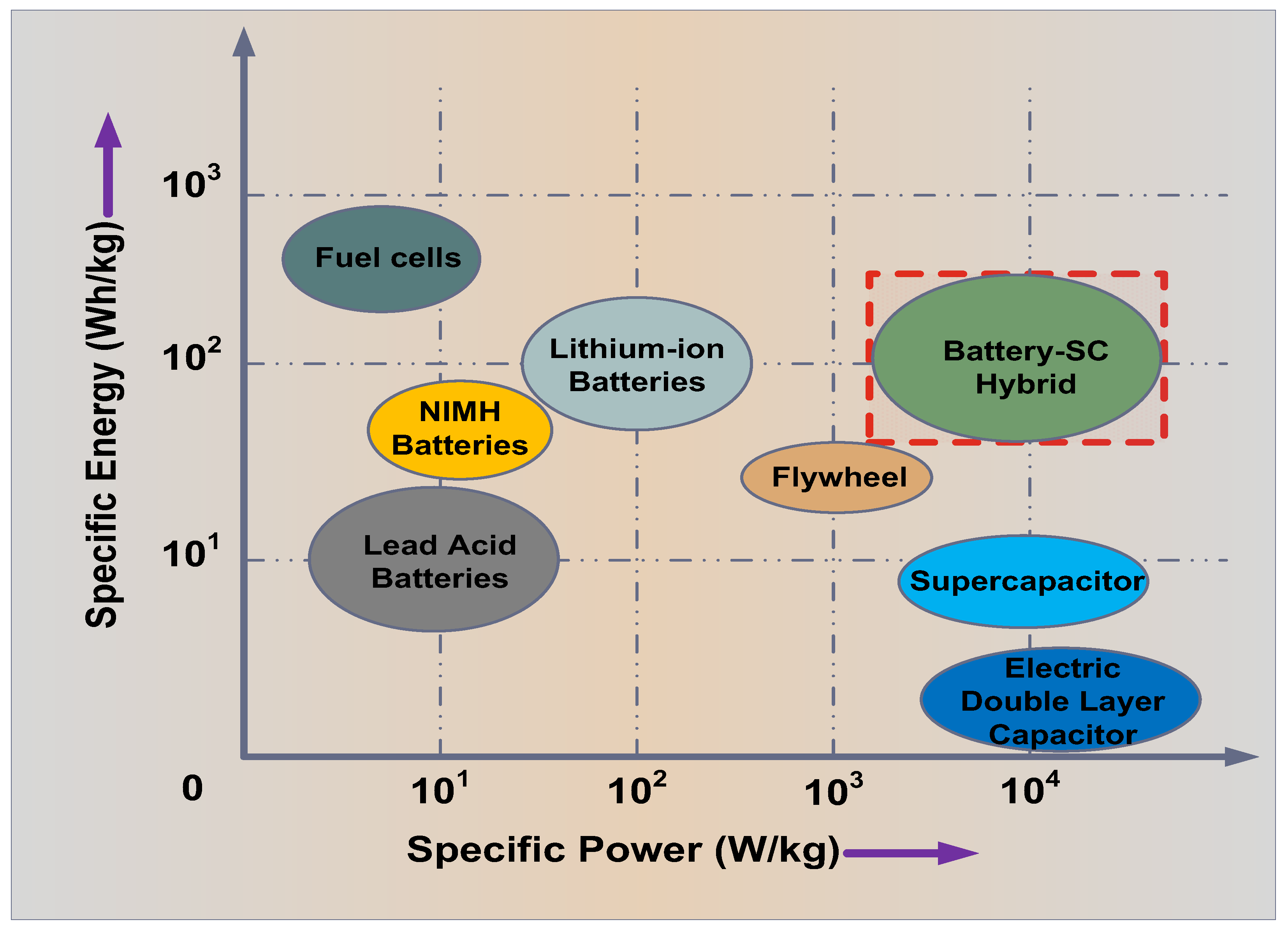
Therefore, combining batteries and SC to form a hybrid energy storage system (HESS) is an excellent solution to overcome individual limitations due to their complementary behaviour [14]. In such a composition, the battery is designated to supply the constant continuous power requirement at a constant current value. In contrast, SC is strategized to deal with the transient power demands, recovery of the power supplied from the battery at light load conditions, and the absorption of regenerative braking energy. In addition, the inclusion of SC avoids oversizing the battery pack and the consequent increase in weight, cost, and depth of charge/discharge cycles [15]. The battery and SC complement each other in the HESS to incorporate the high energy density and power density required for EV powertrain operation. Its comparison with various other energy storage technologies [14,16] is presented in the Ragone plot in Figure 1.

Figure 1.
Ragone plot to demonstrate the importance of lithium–ion battery/SC HESS. Red dashed box shows that it is the HESS which is selected for the research work.
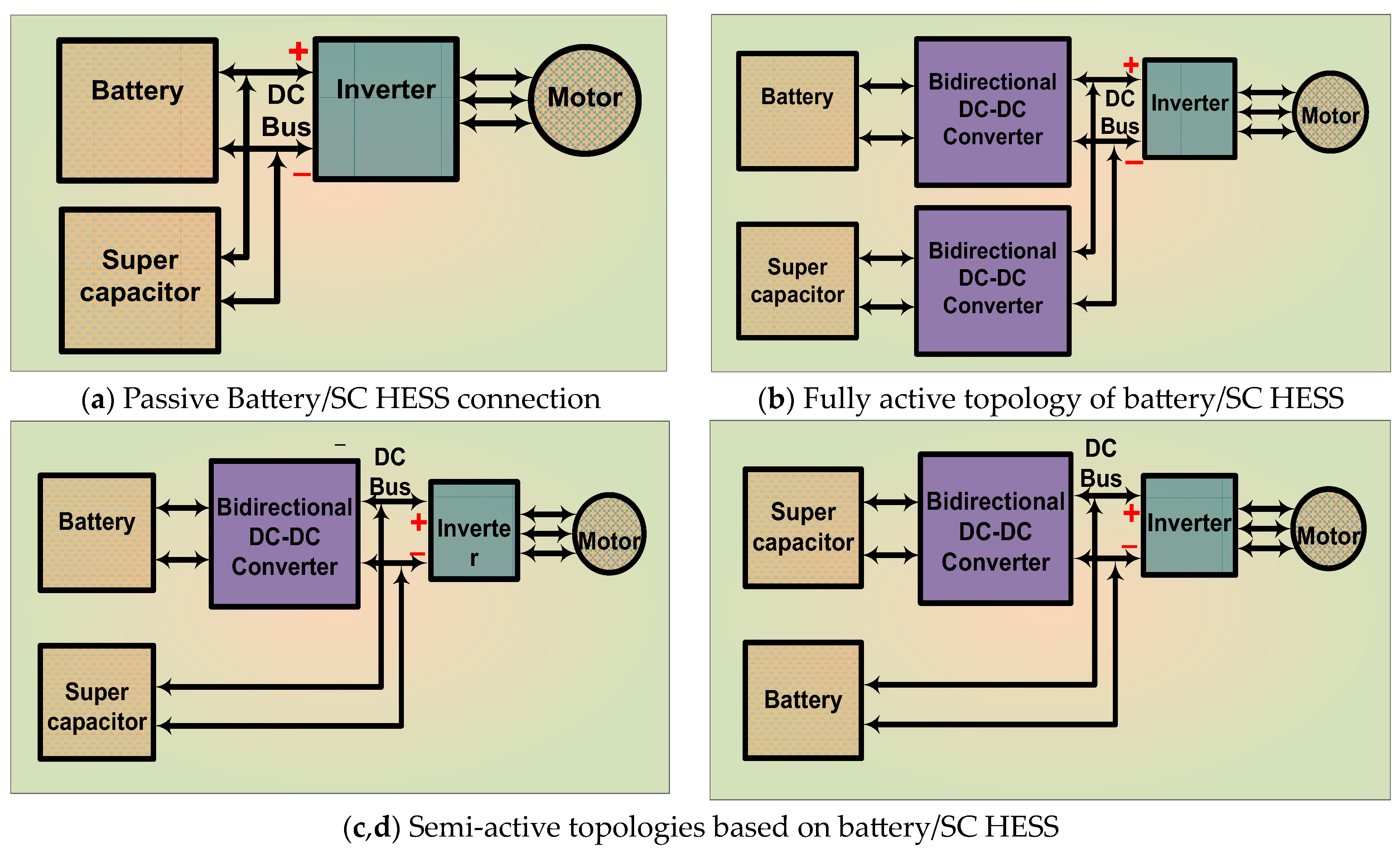
Constant DC link voltage is expected to be fed to the inverter to drive the motor load in the EV powertrain. Bidirectional configurations are necessary to achieve improved performance and efficiency in power transfer [17]. Interconnection of the battery and SC is conducted with different converter topologies depending on the dynamics of the load side [18] and is presented in Figure 2. A conventional parallel connected fully active topology for HESS, and its detailed operation is provided in [19], in which controlling the energy transfer is easy to implement. However, efficiency drops due to the presence of two converters. To overcome this drawback, the size of the DC link capacitor must be increased, resulting in sizing issues. On the other hand, the passive HESS connection is simple and straightforward. Nevertheless, the power transfer to the DC bus is not controlled. It is further inferred that the semi-active topology is a good trade-off between the two topologies, as mentioned above, in regulating energy transfer based on the comparative study presented in [20,21]. The SAT-BDC has a simple design at low cost, overcoming the drawbacks of both fully active and passive bidirectional topologies [22], and it is best suited for the research problem in consideration. Further, the primary objective of SAT-BDC operation is to ensure that a constant continuous current is drawn from the battery pack by including SC to handle the transient variations of the energy exchange. Simultaneously, it is crucial to maintain a constant DC link voltage at the output of the topology connected to HESS so that the inverter and drive performance is improved in the EV powertrain.
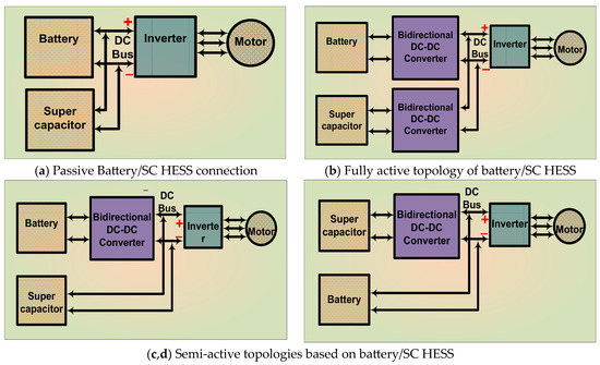
Figure 2.
The different battery/SC configuration approaches for EV powertrain (a–d).
In general, the input current and the output voltage are regulated in a basic bidirectional DC–DC converter (BDC) by the voltage-current (VI) control method by applying PID compensators [22]. However, the conventional PID controllers operate independently and need individual tuning parameters with negligent reciprocation between multiple control loops. They fail to effectively confront the multifaceted current research problem since multiple variables interact simultaneously. Also, tuning the controllers is tedious when power splitting between battery and SC is involved [13,23]. Therefore, a robust and reliable control approach is necessary.
Various approaches to control the energy flow from the HESS are reported in [21,24]. The artificial neural networking and fuzzy logic control approaches show improvement in minimizing the overshoot compared to classic controllers without using the mathematical model of the converter [25]. However, effective data-driven control methods are too complex to design due to the necessity of large amounts of data, which is not suited for low-cost, low-power EV applications [26]. The sliding mode control is tested for BDC in [27], which is further improved by including the extremum-seeking control strategy in [28] without the actual model, which is not flexible enough to be applied for dynamic EV operating conditions. The integrated optimization problem to develop the energy split between a battery and supercapacitor utilizing the dynamic programming approach using a preset cost function is presented in [29]. Further, approximate dynamic programming is employed to develop optimal and flexible switching of BDC, as explained in [30]. However, dynamic programming is computationally expensive and unsuitable for real-time applications. The different control approaches and MPC are compared and summarized in Table 1.

Table 1.
Comparison of different control approaches and model predictive control.
It is evident that MPC is best suited for plants with accurate models with multiple control objectives, such as constant battery current and DC link voltage regulation in SAT-BDC. However, computational cost and complexity increase with the system’s nonlinearity [38]. The interconnected control objectives are optimally achieved with proper management of the control output (duty cycle D in this case) to minimize the difference between the actual system state and the desired reference value with better flexibility and controllability. The constraints with suitable safety limits are imposed to ensure the system limitations with proper weightage [39]. Predicting the future behaviour of the system model is quite significant in EV powertrain applications to allocate the power sharing between the battery and SC, which is unique in this control approach. In [40], a flexible design of MPC is applied to a boost converter to achieve better transient operating conditions with a DC power source and a simple constant load. A hybrid MPC is proposed to optimize the switching of the DC–DC converter in microgrids, considering stability against existing disturbances both in transient and steady states [41]. Still, it fails to address the issue of variable current discharge from the battery.
Furthermore, to address the challenges posed by the long-life expectancy of batteries and improved performance of EV powertrain operation, the use of supercapacitors (SCs) has been proposed in the existing literature. However, developing an effective control strategy to exploit transients and improve efficiency is still under consideration. The classical voltage current control approaches separately address the two variables (i.e., output voltage and the input/source current) in a BDC. Also, conventional VI controllers fail to tackle the issue of interactions between the two variables, i.e., the current drawn from the battery and the DC link voltage. The idea of applying the flexible NMPC approach with future predicting behaviour is extended to the specific application to improve the performance of the lithium–ion battery in EV powertrain in this research work. To realize the novel approach, HESS, including the lithium–ion battery and SC, is considered with SAT-BDC having a variable load sequence. Therefore, this research work focuses on exploring the potential of a semi-active topology of the bidirectional DC–DC converter (SAT-BDC) as represented in Figure 2c with SC directly connected to the DC bus with a reliable and robust nonlinear model predictive control to regulate the battery current under the prescribed value so that the objective of improving the battery performance is achieved along with DC-link voltage tracking. The different prioritizations are tested with the constraints above to optimize the performance of the proposed system further. The significant contributions of the proposed research work are:
- Modelling and design of semi-active topology of the bidirectional DC–DC converter (SAT-BDC) to transfer energy from a HESS incorporating the mathematically modelled lithium–ion battery and supercapacitor (SC) to a variable load model in the open loop to validate the concept.
- Investigation of the performance of the applied nonlinear model predictive control (NMPC) to enhance the operation and life span of the lithium–ion battery pack by simultaneously maintaining constant battery current and regulating DC link voltage at the output by tracking its reference value with different prioritizations.
- Simulation of individual case studies to validate the impact of different prioritizations of the selected variables and the difference in the performance of the system.
The rest of the paper is structured in the remaining five sections. The system components and their mathematical models are discussed in Section 2. The configuration of the proposed system is presented along with the application of the NMPC control architecture described in Section 3. The system parameters considered for the simulation study and the detailed result analysis are presented in Section 4. The conclusion is reported in Section 5.
2. Modelling of the System Components
This section describes the physical components with accurate mathematical modelling. A second-order resistive capacitive (2-RC) cell model of the lithium–ion battery is derived from the literature in Section 2.1. A suitable SC model is also designed in Section 2.2. Further, commercially available suitable lithium–ion battery and SC with the nearest matching parameter values are selected. The variable load current sequence is generated in the MATLAB/Simulink platform to replicate the motor drive and inverter operation, discussed in Section 2.3. Further, the mathematical modelling of SAT-BDC is also conducted using state-space analysis in Section 2.4.
2.1. Battery
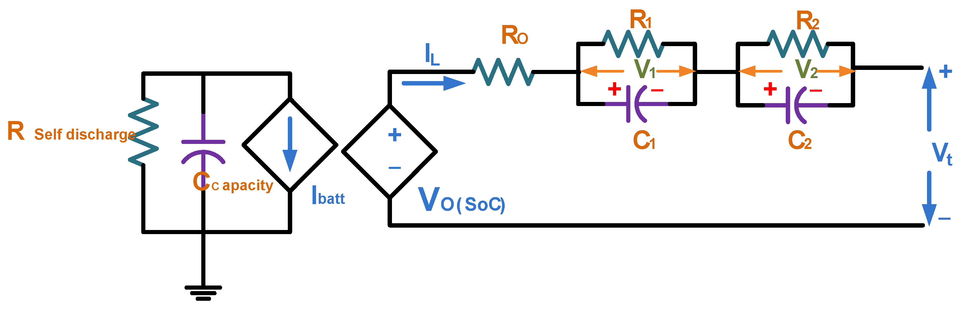
The lithium–ion battery with high energy density must be able to provide the desired voltage rating and capacity to drive the EV powertrain system continuously. This is achieved by developing a battery pack consisting of several individual lithium–ion cells in a series–parallel combination [31]. The exact electrochemical process inside the cell is difficult to comprehend. Therefore, the behaviour and performance of the lithium–ion cell are realized based on the electric equivalent circuit model (EECM), which is a more straightforward approach to modelling the dynamic operation using voltage sources, resistors, and capacitors, as presented in Figure 3. The accurate electrical battery runtime 2-RC model circuit is chosen [42] in this analysis since the 2-RC model is considered to be the best trade-off between accuracy and sizing of the battery [43,44].
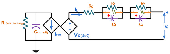
Figure 3.
Electrical equivalent cell model of lithium–ion battery.
The parameters, namely terminal voltage (Vt), open-circuit voltage (Vo), the battery current (IL), capacity (C) in Amp-hour, and the state of charge (SoC) of the battery in %, are estimated using the electrical equivalent circuit modelling of the cell. The relevant equations are referred from [43,44,45,46,47] as shown below.
Here, Ccapacity is the usable capacity, Cinitial is the initial nominal capacity of the battery in Ah mentioned in the nameplate, f1(N) is the cycle number correction factor, and f2(T) is the temperature-dependent correction factor, which is set as 1 since it is not varied much. However, the cycle number correction factor is provided as,
where k1 = 4.5 × 10⁻³ and N are the cycle number, it is observed that the usable capacity of the battery Ccapacity does not depend on current variation. Instead, it is represented by a current-controlled source Ibatt to influence the voltage value Vo dynamically. Also, Rselfdischarge in Figure 3 represents the losses when the battery is unused. Further, Vo is dependent on SoC, and its average value is a monotonically increasing function. The SoC is the ratio of the usable current capacity to its nominal initial capacity value. The relationship between Vo and SoC can be represented by a third-order polynomial equation, as shown below.
Vo depends on SoC, and its average value is a monotonically increasing function. a0, a1, a2, and a3 are the constant values based on the manufacturing materials of the battery.
In addition, the SoC is defined as follows for discharging operation:
where SoCo is the initial SoC value of the battery.
The general equation for the terminal voltage Vt is provided as follows:
RO, the series ohmic resistance, is responsible for the voltage drop when the load is introduced. Ri and Ci are the i-th polarization resistance and i-th polarization capacitance. i = 2 in the present research case since the second-order resistive, while the capacitive (2-RC) cell model is chosen. The RC networks are responsible for the transient operating conditions. Therefore, the Equation (5) is reduced to
where
These equations can be further used for SoC estimation and temperature dependency of the parameters of the battery. R0, R1, R2, C1, and C2 values depend on the SoC and the battery current value IL. The values corresponding to the RC parameters at 60% of SoC are chosen because it is the mean average condition in a battery charge–discharge cycle between 100 and 20%, as shown below in Table 2.
Table 2.
Battery specifications and the parameter values corresponding to 60% SoC.
2.2. Supercapacitor
SC is the high-power density storage applied to the system to instigate transient power management. The actual structure of the SC is depicted in Figure 4a. The operation with the mathematical modelling of the SC is derived from [44]. In this work, the 2-RC model is considered to study the system’s dynamic behaviour [18]. It includes a leakage resistance Rf, two branches with non-linear capacities, and different voltages. The circuit is shown in Figure 4b.
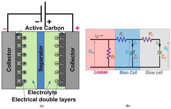
Figure 4.
(a) Structure; (b) Electrical equivalent of the model of the supercapacitor.
The first branch is the fast/main cell representing the charging phases and modelled by resistance R1 and non-linear capacitance value C1, which is calculated using the following formula:
where C0 is a constant capacitance, and CV is a constant value with unit Capacitance/Volt. The nonlinear capacity C1 is decided by the voltage between the terminals of the main cell V1.
The voltage V1 is well-defined as
Whereas the current i1 is denoted in terms of instantaneous charge Q1 and capacity C1 in the following equations.
The instantaneous charge Q1 is defined by
The second cell is the slow branch representing the redistribution of the charges, which is modelled by resistance R2 and capacitance C2 with larger time constants.
The voltage V2 is provided by
The leakage resistance Rf signifies the self-discharge of energy throughout the process, and the leakage current value through the Rf is negligible in the circuit operation. The following equation defines the voltage across the SC:
where USC and ISC are the voltage and current of the SC, respectively, NP-SC and NS-SC provide the numbers of parallel and series connections.
The final capacitance value of the SC is provided by
In this research work, the 2-RC, as mentioned above, model is utilized. The specified parameters mentioned in the equations are calculated. BMOD0063 P125 B04/B08 by Maxwell Technologies is the nearest available SC module, best suited for practical conditions and theoretical calculations. The finalized values to be validated by the simulation process are arranged in Table 3.
Table 3.
Specifications and the parameter values of supercapacitor.
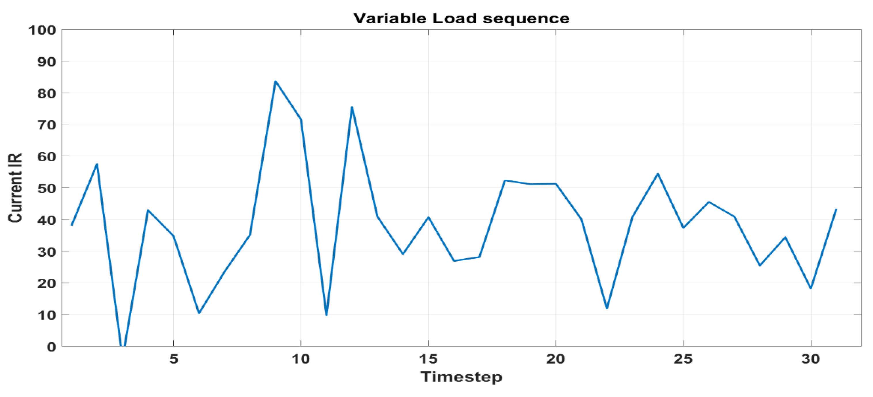
2.3. DC-Link Load Current Generation
For any constant load, the performance of the BDC is already achieved in [28]. However, in this research work, the variable load must be considered to realize the motor drive load connected to an inverter in an EV powertrain under realistic conditions. The load current sequence is generated by adding Gaussian noise with the average value. The average value of the variable output current sequence is kept at 30A for the simulation purpose and is generated in MATLAB to replicate the variable load model. The generated load current waveform is presented in Figure 5.
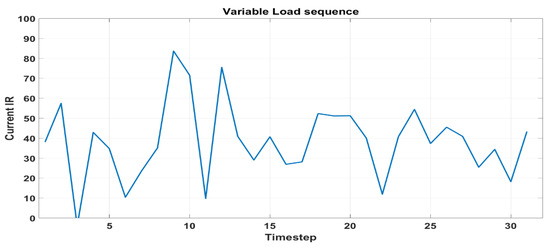
Figure 5.
Generated variable current sequence at the DC link.
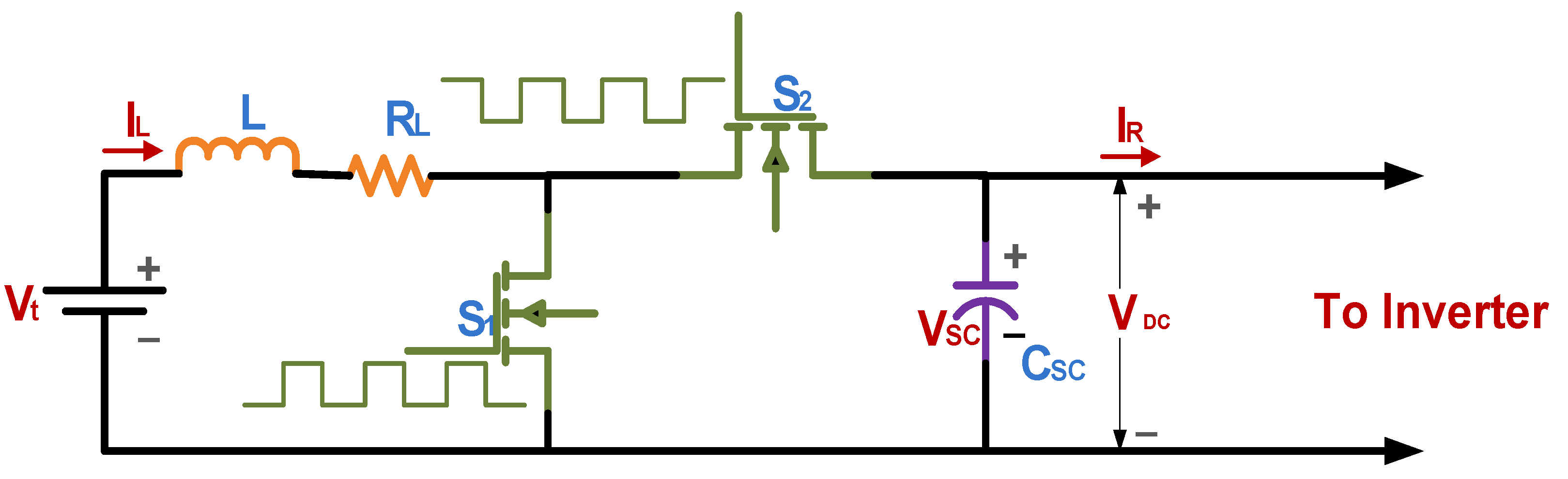
2.4. Semi-Active Topology of Bidirectional DC-DC Converter (SAT-BDC)
The structure of the SAT-BDC utilized in this work is simple and has a reduced component count because the filter capacitor has been replaced with SC. This structure has the advantage of limiting the voltage ripples during the bidirectional energy flow. Moreover, connecting the SC directly to the output side (DC bus in EV applications) aids the controller in maintaining the constant DC link voltage. In addition, SC acts as a low-pass filter for the lithium–ion battery without any additional components. The filtering effect depends on the SC capacity, which is sufficient to manage the fluctuations during the transient operating condition. As mentioned in [20], the presence of SC effectively minimizes the variations in the battery current level. The circuit diagram of SAT-BDC is depicted in Figure 6.
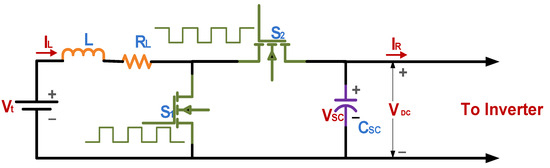
Figure 6.
Semi-active topology of bidirectional DC–DC converter for HESS operation.
When switch S1 is on and switch S2 is off, the dynamics of the SAT-BDC are governed by (18)–(20) [18].
And when the switch S1 is off and the switch S2 is on, the dynamics of the converter are governed by
The average dynamics over one switching period are thus provided by
Here
The circuit parameters of the SAT-BDC topology inductor, the series resistance of the inductor, and the capacitor values are calculated from the design equations [31,51] developed in the steady state. The selected parameter values are tabulated in Table 4, as shown below.
where R is the variable load resistance value, k is the source side voltage ripple factor, usim is the duty cycle, f is the switching frequency, and RL is the series effective resistance of the inductor.
Table 4.
Specifications and the parameter values of SAT-BDC.
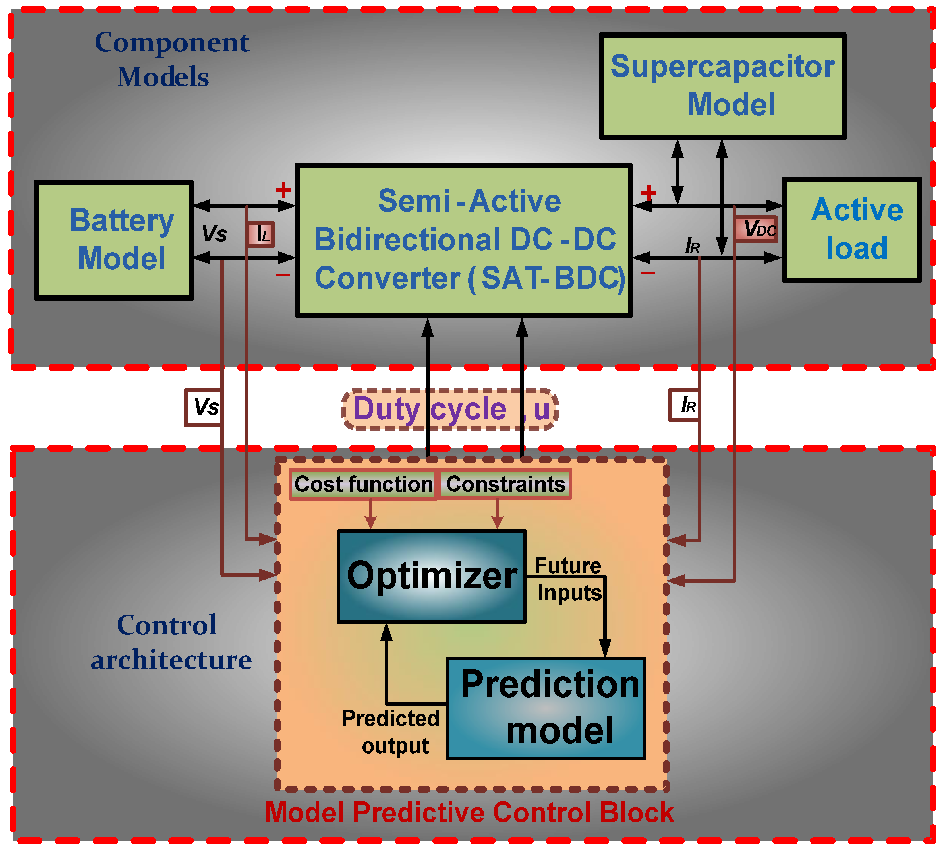
3. Configuration of the Proposed System with Nonlinear Model Predictive Control
The mathematical model of an SAT-BDC [31] with an active variable load (generated variable current sequence to replicate the load model of EV drivetrain), as mentioned in Section 2.3, is developed in MATLAB. It is connected to the mathematical model of the battery system under consideration. The open-loop performance is observed at first to verify the validity of the designed mathematical model. The voltage values are selected based on the standard values obtained from the battery and motor design values. Furthermore, NMPC is employed to regulate the two constraints, namely, the inductor current (IL) (the current discharged by battery) of the SAT-BDC and the DC link voltage (VDC) across the variable load under consideration simultaneously. The time horizon is chosen to achieve and realize the steady-state condition. The time step in each prioritization is different depending on the simulation parameters. Moreover, the filter capacitor of the converter is replaced by the mathematical model of SC with a suitable value, as mentioned in Section 2.2. The NMPC is modified accordingly. The complete configuration consisting of a lithium–ion battery with an SC acting as the HESS and the modified SAT-BDC, whose operation is regulated by NMPC, is shown in Figure 7. As mentioned earlier, the central objective is to compute the duty cycle of SAT-BDC, ensuring that the battery current remains within its constraints, maintaining a constant value, and precisely tracking the DC-link voltage reference. Both targets are accomplished by suitably applying non-linear model predictive control in this research work.

Figure 7.
Schematic representation of the proposed system configuration.
Proposed Nonlinear Model Predictive Control Strategy
The modes of operation of the SAT-BDC are based on the switching conditions. The NMPC operation depends on the constraints considered. The main objective of the research is to derive an optimal switching strategy to maintain the DC link voltage at the reference level and keep the inductor current at a constant value with the help of SC.
At first, the NMPC model is discretized using Euler discretization to obtain the following matrices:
A, Bi, and Bv are the constraints developed based on the state space analysis.
Finally, the cost function for the NMPC is provided by
where , k is the iteration number, N is the time horizon, and ϵ is the inequality constant to convert the inequalities of the constraints to the equality. The inequality constant is applied to define the soft constraints since there is a mutual interaction that is allowed in NMPC.
The optimization problem is thus provided by
Such that
In this work, since the NMPC employed for the SAT-BDC is flexible, simulations are conducted based on the different priorities of the constraints, namely the battery current and DC link voltage. There is an interaction between the considered constraints inductor current IL and the DC link voltage VDC; equality is required to establish and prioritize the constraints. Since NMPC allows establishing the priority of one constraint over other using inequality constraint ϵ, the user can utilize this function to give prominence to the individual constraint based on its significance in the application. In EV applications, maintaining constant battery current is more significant than regulating DC voltage. Hence, the focus is provided to the same. The actual impact of the different prioritization of these variable parameters is studied and analyzed. The choice of prioritization plays a key role in the optimum performance and health of the battery. The results are presented in different cases with the parameters derived in Section 4.
4. Results and Analysis
The detailed study of the SAT-BDC connected to a variable active load current with a HESS involving a lithium–ion battery and SC is conducted in this work to corroborate the conceptual interpretation and mathematical analysis of the proposed system. The converter is controlled by the NMPC approach with the intent to discharge the battery at a constant current value and regulate the DC link voltage, tracking a reference value of 72~V. Different operating conditions and priorities are investigated and presented in five different sub-sections further.
Initially, the open-loop operation of the converter is conducted with only a lithium–ion battery as the source in Section 4.1. Further, the closed-loop operation of the converter topology is conducted with the NMPC approach in Section 4.2. To improve the performance of the battery current, SC replaces the filter capacitance of the BDC to make it a semi-active BDC topology with HESS. The NMPC algorithm is modified accordingly, as described in Section 4.3. The system is examined further by prioritizing the DC link voltage and the inductive current to observe the performance of the system in Section 4.4 and Section 4.5, respectively.
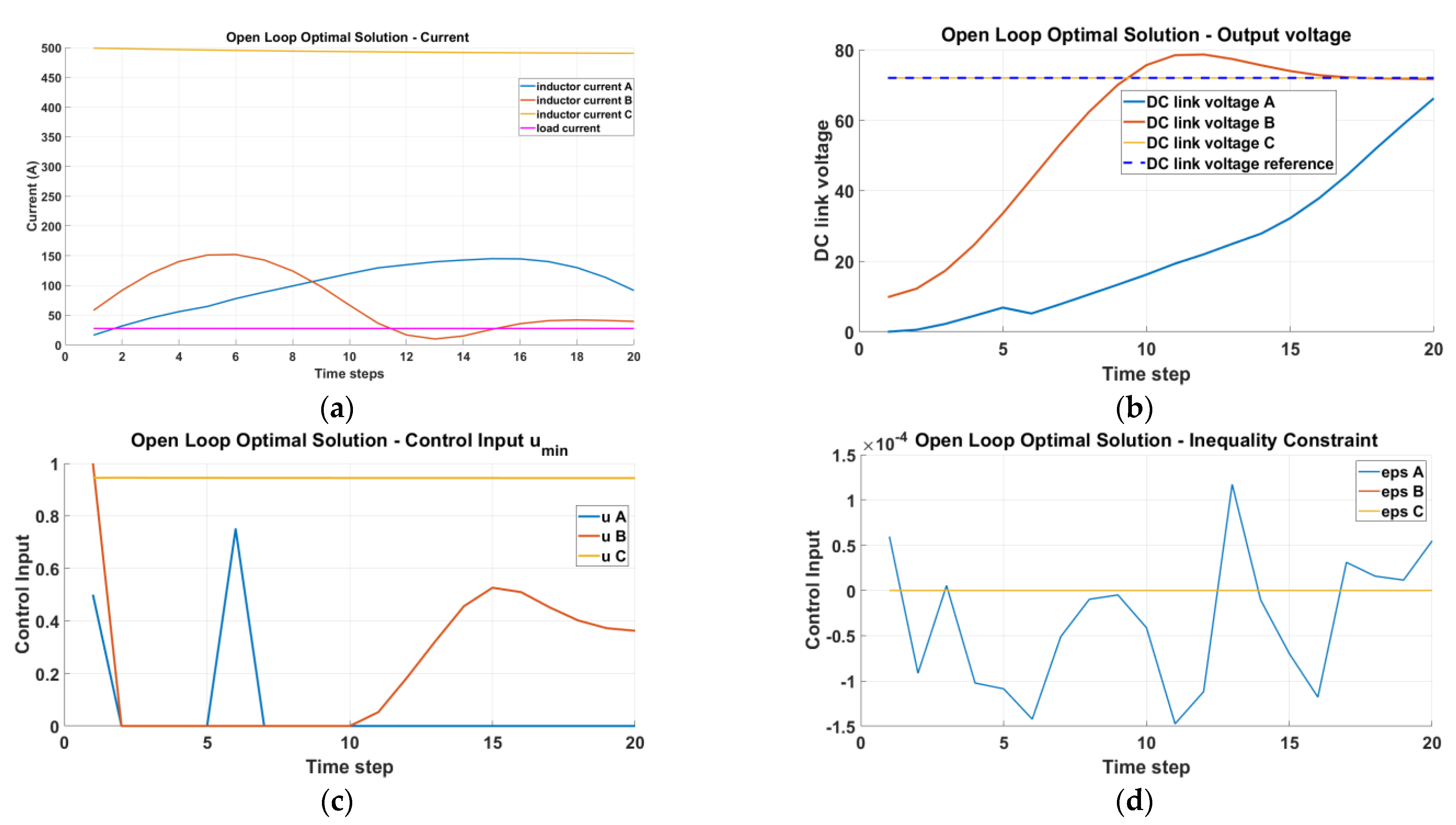
4.1. Open-Loop Optimal Solution without Supercapacitor
The open-loop optimal solution is tested with MATLAB simulation to validate the conceptual modelling and design with three initial conditions: A, B, and C. The open-loop simulation is conducted without applying the objective function to the constraints in NMPC. However, it is allowed to define constraints, and the control output duty cycle is not controlled. Instead, the control output duty cycle in the open-loop simulation is computed based on the theoretical calculations in coding for the next N timesteps.
This is demonstrated for all three different initial conditions: A, B, and C. In Scenario A, all the parameters are considered to have zero initial values. In Scenario B, random values are taken at the initial condition. Scenario C consists of the actual parameter values calculated from the design equations at the initial condition. The parameters selected for the NMPC tuning are presented in Table 5. The inductor current IL, the DC link voltage VDC, the duty cycle usim, and the slack variable ϵ are represented in Figure 8.
Table 5.
Simulation configuration of the open loop for the NMPC approach.
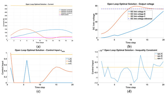
Figure 8.
Optimal open-loop solution with initial conditions A, B, and C, and corresponding waveforms (a) current waveforms; (b) output DC-link voltage waveforms; (c) duty cycle; and (d) Epsilon, the slack variable.
In all three scenarios, it is evident that the system’s current remains stable without oscillation, and the voltage progressively approaches its reference value. It should be noted that the chosen time horizon is sufficient for the open-loop system to remain stable, as indicated in the subsequent sections. However, in Scenario A, the system voltage value does not reach a steady state within the designated time horizon. In contrast, Scenario C has reached a steady state, resulting in the optimal solution to maintain a constant duty cycle. For Scenarios A and B, the steady-state outcome is not attained, and the optimal solution involves initially applying a high-duty cycle and gradually reducing it over time. The feasibility of the problem is evident from the plot depicting the value of the slack variable, which remains within acceptable bounds. Figure 8 above shows the open-loop optimal solution computed by the MPC for three different initial conditions. In Scenario C, where the system has reached a steady state, the optimal solution is to keep the same steady-state value without any modification in the feedback provided, and there are no disturbance signals. However, in the practical application of EV, the disturbance signals are present in the form of braking and variable load dynamics. Therefore, NMPC control must be applied to the mentioned variables/constraints.
4.2. Closed Loop Simulation, without Supercapacitor
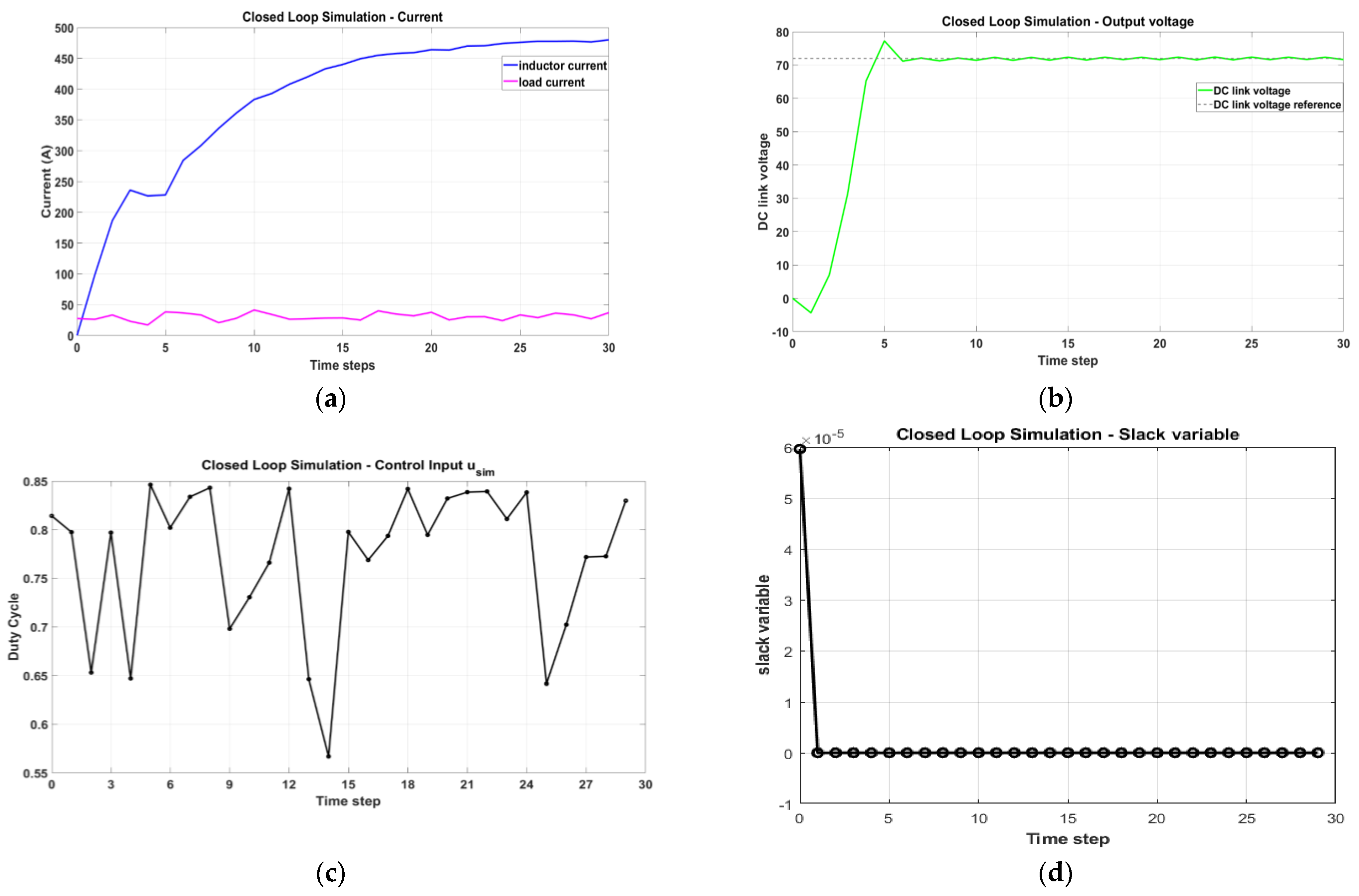
This section presents the results of the closed-loop system, where the duty cycle for timestep zero is applied at each subsequent timestep. The NMPC can simultaneously control the voltage to a particular reference value and the steady non-oscillatory inductor current in an effective manner. From the user’s point of view, it is a trade-off whether it is more important to reach the DC-link voltage reference quickly or keep the current as constant as possible. When there is no SC, the system has faster system dynamics, which makes it necessary to use a smaller timestep for the NMPC implementation. Still, it also allows for a shorter time horizon. Nonetheless, the chosen time horizon is sufficient to achieve the desired control objectives, as evident from the performance of the controller. The simulation parameters of the configured system are presented in Table 6. Figure 9 represents the respective waveforms of the inductor current with the output current, DC link voltage, duty cycle, and inequality constraints.
Table 6.
Simulation configuration of the closed-loop operation of SAT-BDC without SC.
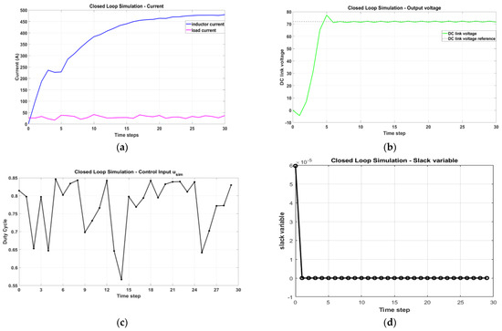
Figure 9.
Optimal closed-loop operation with the lithium–ion battery without supercapacitor integration: (a) Current waveforms and (b) output DC-link voltage waveforms; (c) duty cycle of SAT-BDC switches; and (d) Epsilon, the slack variable.
Figure 9a shows that a very high current is drawn from the battery, which is not appreciated for its longer life. The presence of SC is necessary to regulate the battery current under a certain safe limit. The voltage and duty cycle waveforms are presented, showing the effectiveness of NMPC control. Since the battery current performance is significant, the current is prioritized 100 times more than the DC-link voltage constraint in NMPC.
4.3. Closed-Loop Simulation with the Integration of Supercapacitor
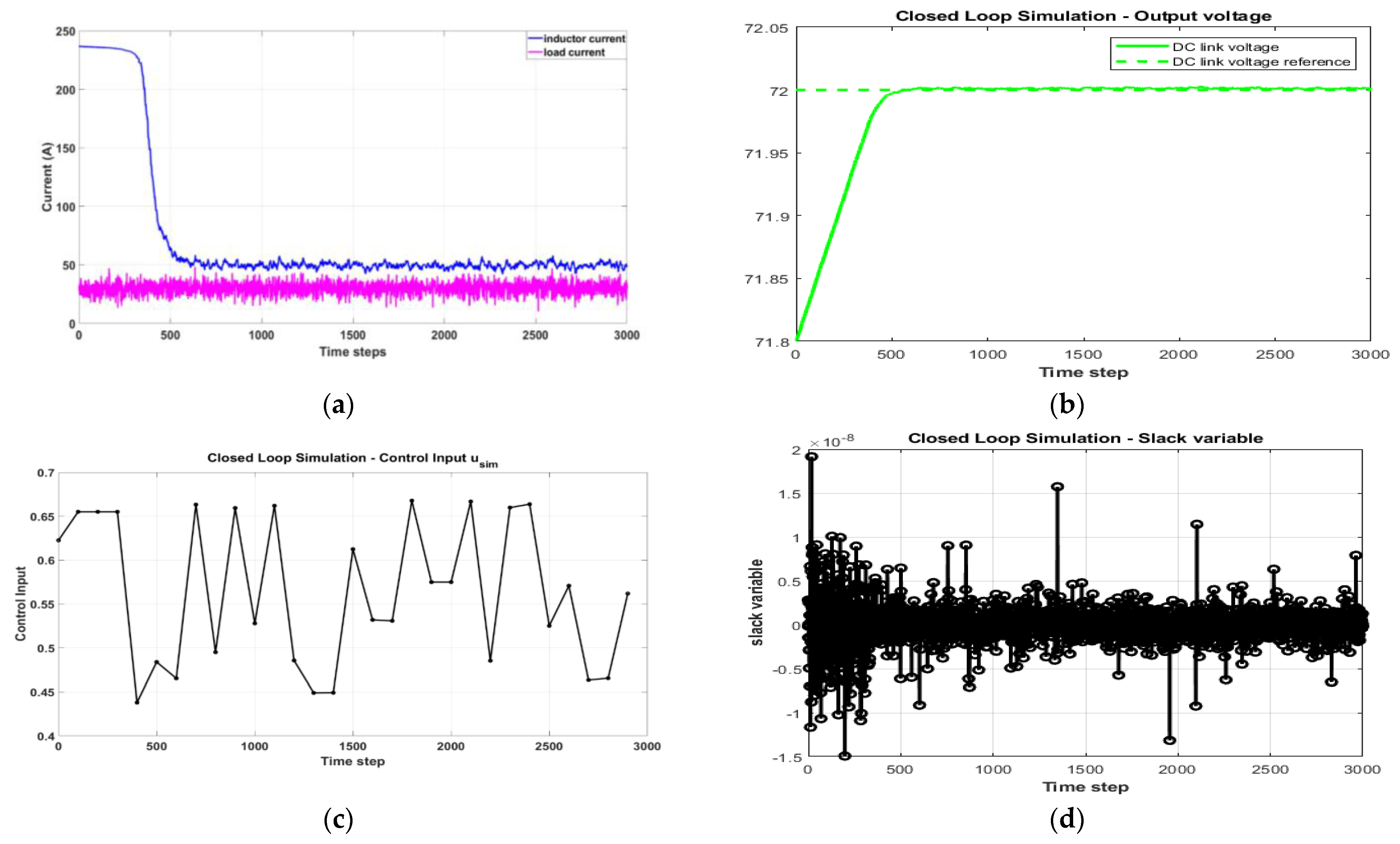
Incorporating a supercapacitor leads to a more stable output voltage compared to a system without it. However, achieving the desired reference voltage takes longer due to the time delay introduced by the supercapacitor. It is important to note the timescale difference compared to the previous figures. The high capacitance value allows for longer timesteps for the nonlinear MPC, contributing to improved computational efficiency. The configuration parameters of NMPC are listed in Table 7. Both constraints are allotted equal weightage. Figure 10 represents the inductor current, DC link voltage, duty cycle, and equality constraints. In this scenario, the system configuration remains the same as in the previous simulation, but the noise on the inductor current increases. Despite the increased noise, the controller effectively controls the DC link voltage, closely tracking its reference. However, more significant variations in the inductor current are observed, highlighting the impact of increased noise on system dynamics.
Table 7.
Simulation configuration of closed-loop NMPC with the integration of SC in SAT-BDC.

Figure 10.
Closed-loop operation of SAT-BDC with HESS with the integration of supercapacitor: (a) Current waveforms obtained; (b) DC-link voltage waveform; (c) obtained duty cycle of the SAT-BDC switches; and (d) Slack variable and its variation.
4.4. Closed-Loop Simulation of HESS with Voltage Prioritization
In the previous section, equal prioritization is provided for both the constraints, and as a result, noise is observed in the inductor current waveform. Hence, the priority for the constraints is altered, and higher priority is provided to DC link voltage. Table 8 denotes the simulation configuration of the system under voltage prioritization. Figure 11 represents the corresponding waveforms under voltage-prioritized conditions. In this simulation, the primary control objective is to prioritize the regulation of the DC link voltage. The figures demonstrate that the DC link voltage closely follows its reference, indicating effective control. However, the inductor current exhibits oscillations due to the controller’s prioritization of voltage control.
Table 8.
Simulation configurations of closed-loop under voltage priority condition.
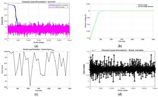
Figure 11.
Closed-loop operation of SAT-BDC with HESS using voltage prioritization throughout the time horizon: (a) Inductor current and variable output current waveforms; (b) DC-link voltage waveform tracking reference; (c) duty cycle for SAT-BDC switch control; (d) Slack variable and its variation.
4.5. Closed-Loop Simulation of HESS with Current Prioritization
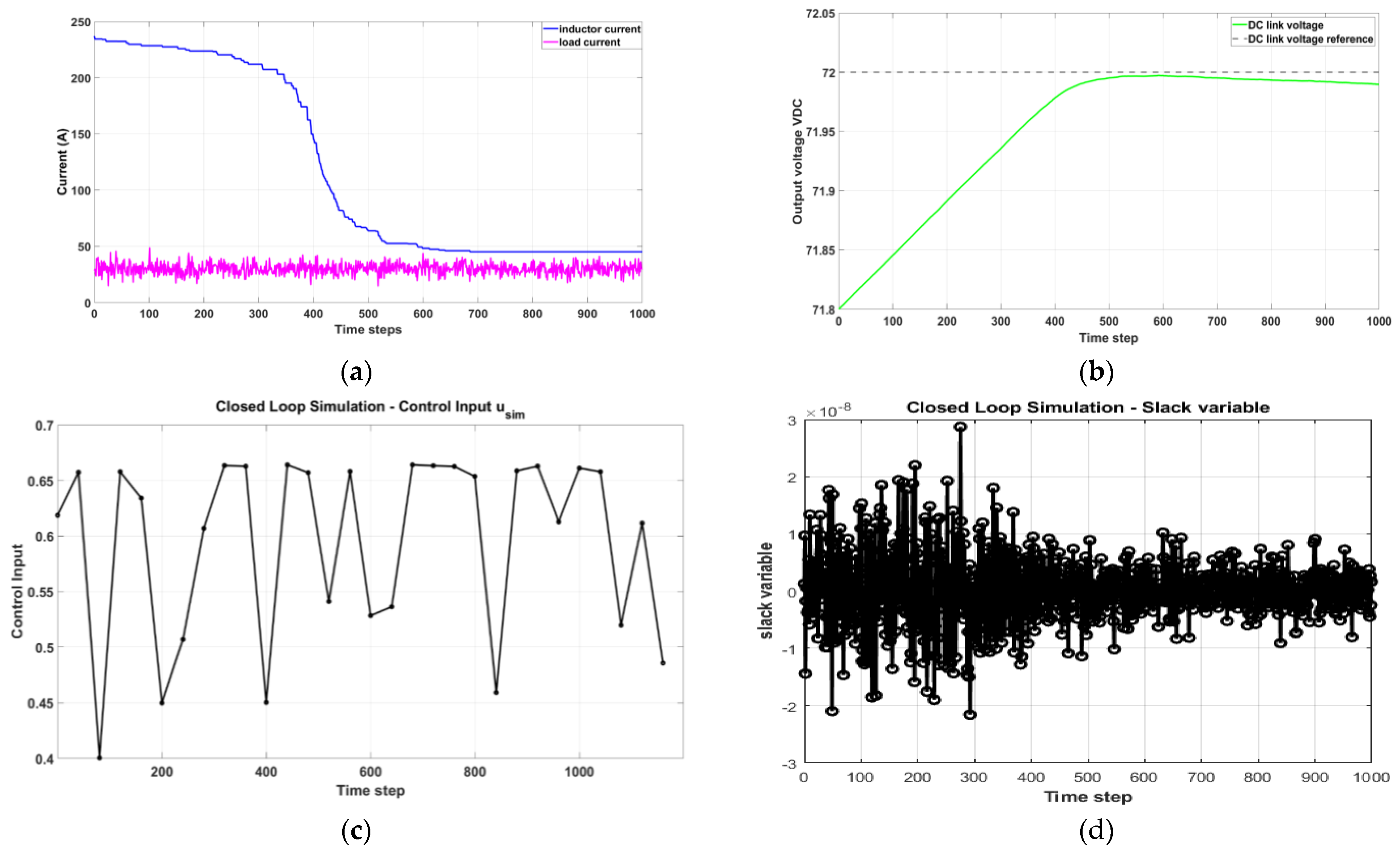
In this simulation, the primary control objective is to prioritize maintaining a constant current from the battery source. As a result, the inductor current exhibits significantly fewer variations than the previous scenarios. However, the improvement in current control comes at the expense of the DC-link voltage control. Table 9 presents the system configuration parameters and the priority of the constraints considered in the simulation. Figure 12 shows the respective waveforms, and it is visible that the controller struggles to track the voltage reference accurately in this case. Still, voltage variations are under the considered limits and acceptable for the particular application. It must be observed that the time steps required to obtain the steady state are also reduced, which is an added advantage in the practical scenario. This scenario is best suited for the EV powertrain application since the battery current performance is better compared to previous case studies, and the voltage performance is still under limits. In addition, the duty cycle is also between 0.45 and 0.65, which is almost ideal for the operation of BDC.
Table 9.
Simulation configuration of closed loop under current priority condition.
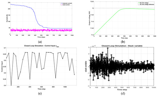
Figure 12.
Closed-loop operation of SAT-BDC with HESS using current prioritization: (a) Inductor current and variable output current waveforms; (b) DC-link voltage waveform tracking reference; (c) duty cycle for SAT-BDC switch control; (d) Slack variable and its variation.
5. Discussion
In this simulation, the primary control objective is to prioritize maintaining a constant current from the battery source. As a result, the inductor current exhibits significantly fewer variations than the previous scenarios. However, the improvement in current control comes at the expense of the DC-link voltage control. Table 9 presents the system configuration parameters and the priority of the constraints considered in the simulation. Figure 12 shows the respective waveforms, and it is visible that the controller struggles to track the voltage reference accurately in this case. Still, voltage variations are under the considered limits and acceptable for the particular application. It must be observed that the time steps required to obtain the steady state are also reduced, which is an added advantage in the practical scenario. This scenario is best suited for the EV powertrain application since the battery current performance is better compared to previous case studies, and the voltage performance is still under limits. In addition, the duty cycle is also between 0.45 and 0.65, which is almost ideal for the operation of BDC.
The presence of the SC stabilizes the battery performance, which is detected by comparing the waveforms between Section 4.2 and Section 4.3. It is observed that the inclusion of the supercapacitor lessens the switching stress by reducing the average duty cycle value from 0.75 to 0.6. However, in voltage prioritization, the average duty cycle value is increased to 0.75. In contrast, in the current prioritization, the average duty cycle is observed to be 0.55, which provides better performance of the switches in the converter system. This clearly shows that the current prioritization and the equal prioritization condition are much better than the voltage prioritization condition. However, the current prioritization improves the battery performance and life by reducing the current ripples to a great extent, as depicted in Figure 12a. The current prioritization may help increase the battery performance and health due to the improvements in the current waveform. It is evident that voltage prioritization is not preferred in converter systems at low-power EV applications. However, in high-voltage, high-power vehicles, voltage prioritization may be applied, which needs to be explored. Voltage priority is preferred over the current priority of the battery system in distributed generation systems like microgrid applications.
6. Conclusions
This paper explores the challenges associated with controlling the DC link voltage and constant battery current as constraints in the SAT-BDC system with the battery and supercapacitor as sources of HESS. A novel solution is proposed using NMPC, considering the EV powertrain application. Based on the results, NMPC proves to be a powerful optimization technique, capable of precisely regulating the DC link voltage to a specified reference value while maintaining a constant extraction of current from the battery to enhance its life. The effectiveness of NMPC in delivering improved overall performance is demonstrated in this application by utilizing an accurate nonlinear model representation and careful formulation of the optimization problem.
Incorporation of the interaction between the two constraints is conducted through prioritization of the mentioned constraints as a key characteristic in this research. The results of the simulation validate the efficacy of the NMPC approach in regulating the DC link voltage and maintaining a constant current. The integration of a supercapacitor enhances the stability of the output voltage, while the prioritization of control objectives influences the trade-off between the DC link voltage and inductor current control. These findings contribute valuable insights for the practical implementation of NMPC in real-world control systems, helping to optimize performance and achieve desired control objectives based on the application. This research work exhibits the ability of the NMPC method to be more flexible compared to other methods. Based on the results, the current prioritization is better suited for EV powertrain applications to maintain a constant battery output current to increase the performance and life expectancy of the battery, which is the primary source of energy storage.
With its capability to handle multiple control objectives and enforce safety constraints, NMPC emerges as a valuable control strategy for applications, requiring robust and efficient control of complex and nonlinear systems. However, the reliance on accurate models and the associated computational costs warrants further investigation and consideration when applying NMPC in practical implementations. Moving forward, future research could explore advanced model-identification techniques and improved computational strategies to enhance the applicability and scalability of NMPC for diverse control challenges. Additional control objectives can be added to the optimization problem, such as temperature and SoC control of the battery. Overall, the insights gained from this study contribute to the growing body of knowledge in control theory and provide a valuable framework for optimizing DC-link voltage control and constant battery current in practical EV applications.
Author Contributions
Conceptualization, P.S.P.K. and H.C.L.; methodology, P.S.P.K. and H.C.L.; software, P.S.P.K. and H.C.L.; validation, J.N.S., V.S.R., A.S. and P.B.N.; formal analysis, P.S.P.K.; investigation, P.S.P.K.; resources, J.N.S.; data curation, P.S.P.K.; writing—original draft preparation, P.S.P.K.; writing—review and editing, J.N.S., V.S.R., A.S. and P.B.N.; visualization, P.S.P.K. and H.C.L.; supervision, J.N.S.; project administration, J.N.S. and V.S.R.; funding acquisition, J.N.S., V.S.R. and A.S. All authors have read and agreed to the published version of the manuscript.
Funding
This research received no external funding.
Institutional Review Board Statement
Not applicable.
Informed Consent Statement
Not applicable.
Data Availability Statement
Data are contained within the article.
Conflicts of Interest
The authors declare no conflicts of interest.
References
- Alanazi, F. Electric Vehicles: Benefits, Challenges, and Potential Solutions for Widespread Adaptation. Appl. Sci. 2023, 13, 6016. [Google Scholar] [CrossRef]
- Agajie, T.F.; Ali, A.; Fopah-Lele, A.; Amoussou, I.; Khan, B.; Velasco, C.L.R.; Tanyi, E. A Comprehensive Review on Techno-Economic Analysis and Optimal Sizing of Hybrid Renewable Energy Sources with Energy Storage Systems. Energies 2023, 16, 642. [Google Scholar] [CrossRef]
- Abdelqawee, I.M.; Emam, A.W.; ElBages, M.S.; Ebrahim, M.A. Implementation of a novel hybrid optimizer for energy management of fuel cell/battery/supercapacitor system. Energy Syst. 2022. [Google Scholar] [CrossRef]
- Pedrayes, J.F.; Melero, M.G.; José, M.C.; Norniella, J.G.; Orcajo, G.A.; Cabanas, M.F.; Rojas, C.H. Optimization of supercapacitor sizing for high-fluctuating power applications by means of an internal-voltage-based method. Energy 2019, 183, 504–513. [Google Scholar] [CrossRef]
- Hossain Lipu, M.S.; Hannan, M.A.; Karim, T.F.; Hussain, A.; Md Saad, M.H.; Ayob, A.; Miah, M.S.; Mahlia, T.M.I. Intelligent algorithms and control strategies for battery management system in electric vehicles: Progress, challenges and future outlook. J. Clean. Prod. 2021, 292, 126044. [Google Scholar] [CrossRef]
- Tran, M.-K.; Mathew, M.; Janhunen, S.; Panchal, S.; Raahemifar, K.; Fraser, R.; Fowler, M. A comprehensive equivalent circuit model for batteries, incorporating the effects of state of health, state of charge, and temperature on model parameters. J. Energy Storage 2021, 43, 103252. [Google Scholar] [CrossRef]
- Hannan, M.A.; Hoque, M.M.; Mohamed, A.; Ayob, A. Review of energy storage systems for electric vehicle applications: Issues and challenges. Renew. Sustain. Energy Rev. 2017, 69, 771–789. [Google Scholar] [CrossRef]
- Zhao, X.L.; Wang, L.; Zhou, Y.L.; Pan, B.X.; Wang, R.C.; Wang, L.M.; Yan, X.Q. Energy management strategies for fuel cell hybrid electric vehicles: Classification, comparison, and outlook. Energy Convers. Manag. 2022, 270, 116179. [Google Scholar] [CrossRef]
- Badji, A.; Abdeslam, D.O.; Becherif, M.; Eltoumi, F.; Benamrouche, N. Analyze and Evaluate of Energy Management System for Fuel Cell Electric Vehicle based on Frequency Splitting. Math. Comput. Simul. 2020, 169, 65–77. [Google Scholar] [CrossRef]
- Hossain Lipu, M.S.; Mamun, A.A.; Ansari, S.; Miah, M.S.; Hasan, K.; Meraj, S.T.; Abdolrasol, M.G.M.; Rahman, T.; Maruf, M.H.; Sarker, M.R.; et al. Battery Management, Key Technologies, Methods, Issues, and Future Trends of Electric Vehicles: A Pathway toward Achieving Sustainable Development Goals. Batteries 2022, 8, 119. [Google Scholar] [CrossRef]
- Collath, N.; Tepe, B.; Englberger, S.; Jossen, A.; Hesse, H. Aging aware operation of battery energy storage systems: A review. J. Energy Storage 2022, 55, 105634. [Google Scholar] [CrossRef]
- Robayo, M.; Mueller, M.; Sharkh, S.; Abusara, M. Assessment of supercapacitor performance in a hybrid energy storage system with an EMS based on the discrete wavelet transform. J. Energy Storage 2023, 57, 106200. [Google Scholar] [CrossRef]
- Alobeidli, K.; Khadkikar, V. A new ultracapacitor state of charge control concept to enhance battery lifespan of dual storage electric vehicles. IEEE Trans. Veh. Technol. 2018, 67, 10470–10481. [Google Scholar] [CrossRef]
- Sundén, B. Battery Technologies. In Hydrogen, Batteries and Fuel Cells, 1st ed.; Academic Press: Cambridge, MA, USA, 2019; pp. 57–79. [Google Scholar] [CrossRef]
- Nguyen, B.H.; German, R.; Trovao, J.P.F.; Bouscayrol, A. Real-time energy management of battery/supercapacitor electric vehicles based on an adaptation of pontryagin’s minimum principle. IEEE Trans. Veh. Technol 2019, 68, 203–212. [Google Scholar] [CrossRef]
- Dong, Z.; Zhang, Z.B.; Li, Z.; Li, X.M.; Qin, Z.W.; Liang, C.X.; Han, M.H.; Yin, Y.F.; Bai, J.Z.; Wang, C.Y.; et al. A Survey of Battery–Supercapacitor Hybrid Energy Storage Systems: Concept, Topology, Control and Application. Symmetry 2022, 14, 1085. [Google Scholar] [CrossRef]
- Gorji, S.A.; Sahebi, H.G.; Ektesabi, M.; Rad, A.B. Topologies and control schemes of bidirectional DC–DC power converters: An overview. IEEE Access 2019, 7, 117997–118019. [Google Scholar] [CrossRef]
- Nguyen, N.D.; Yoon, C.; Lee, Y.-I. A standalone energy management system of battery/supercapacitor hybrid energy storage system for electric vehicles using model predictive control. IEEE Trans. Ind. Electron. 2022, 70, 5104–5114. [Google Scholar] [CrossRef]
- Momayyezan, M.; Abeywardana, D.B.W.; Hredzak, B.; Agelidis, V.G. Integrated reconfigurable configuration for battery/ultracapacitor hybrid energy storage systems. IEEE Trans. Energy Convers. 2016, 31, 1583–1590. [Google Scholar] [CrossRef]
- Song, Z.Y.; Hofmann, H.; Li, J.Q.; Han, X.B.; Zhang, X.W.; Ouyang, M.G. A comparison study of different semi-active hybrid energy storage system topologies for electric vehicles. J. Power Sources 2015, 274, 400–411. [Google Scholar] [CrossRef]
- Sankarkumar, R.S.; Natarajan, R. Energy management techniques and topologies suitable for hybrid energy storage system powered electric vehicles: An overview. Int. Trans. Electr. Energy Syst. 2021, 31, e12819. [Google Scholar] [CrossRef]
- Punna, S.; Mailugundla, R.; Salkuti, S.R. Design, Analysis and Implementation of Bidirectional DC–DC Converters for HESS in DC Microgrid Applications. Smart Cities 2022, 5, 433–454. [Google Scholar] [CrossRef]
- Ranjan, A.; Bodkhe, S.B.; Goyal, G.N.; Aware, M.V. Heuristics EMS for HESS of Electric Vehicle to Extended Battery Operation Using Rate Limiter. Adv. Electr. Comput. Eng. 2022, 22, 11–22. [Google Scholar] [CrossRef]
- Hossain Lipu, M.S.; Faisal, M.; Ansari, S.; Hannan, M.A.; Karim, F.A.; Ayob, A.; Hussain, A.; Miah, M.S.; Md Saad, M.H. Review of electric vehicle converter configurations, control schemes and optimizations: Challenges and suggestions. Electronics 2021, 10, 477. [Google Scholar] [CrossRef]
- Cordoba-Arenas, A.; Onori, S.; Rizzoni, G. A control-oriented battery pack model for plug-in hybrid electric vehicle cycle-life studies and system design with consideration of health management. J. Power Sources 2015, 279, 791–808. [Google Scholar] [CrossRef]
- Sankar, R.S.R.; Deepika, K.; Alsharef, M.; Alamri, B. A Smart ANN-Based Converter for Efficient Bidirectional Power Flow in Hybrid Electric Vehicles. Electronics 2022, 11, 3564. [Google Scholar] [CrossRef]
- Karami-Mollaee, A.; Barambones, O. Dynamic Sliding Mode Control of DC-DC Converter to Extract the Maximum Power of Photovoltaic System Using Dual Sliding Observer. Electronics 2022, 11, 2506. [Google Scholar] [CrossRef]
- Trinh, H.-A.; Nguyen, D.G.; Phan, V.-D.; Duong, T.-Q.; Truong, H.-V.-A.; Choi, S.-J.; Ahn, K.K. Robust Adaptive Control Strategy for a Bidirectional DC-DC Converter Based on Extremum Seeking and Sliding Mode Control. Sensors 2023, 23, 457. [Google Scholar] [CrossRef]
- Song, Z.Y.; Hofmann, H.; Li, J.Q.; Han, X.B.; Ouyang, M.G. Optimization for a hybrid energy storage system in electric vehicles using dynamic programing approach. Appl. Energy 2015, 139, 151–162. [Google Scholar] [CrossRef]
- Taheri, B.; Sedaghat, M.; Bagherpour, M.A.; Farhadi, P. A New Controller for DC-DC Converters Based on Sliding Mode Control Techniques. J. Control Autom. Electr. Syst. 2019, 30, 63–74. [Google Scholar] [CrossRef]
- Praveena, K.P.S.; Jayalakshmi, N.S.; Adarsh, S. Fuzzy Logic Based Hysteresis Current Control and Regenerative Braking of BLDC Motor with Battery Equivalent Cell Modelling for Electric Vehicles. Int. J. Renew. Energy Res. 2023, 13, 1406–1417. [Google Scholar] [CrossRef]
- Lakshmi Narayana, R.; Sreeramulu Mahesh, G.; KCheepati, K.R.; Yuvaraj, T. A fuzzy logic based controller for the bidirectional converter in an electric vehicle. Int. J. Eng. Adv. Technol. 2019, 9, 58–62. [Google Scholar] [CrossRef]
- Škugor, B.; Deur, J. Dynamic programming-based optimisation of charging an electric vehicle fleet system represented by an aggregate battery model. Energy 2015, 92, 456–465. [Google Scholar] [CrossRef]
- Stachowicz, K.; Theodorou, E.A. Optimal-Horizon Model Predictive Control with Differential Dynamic Programming. Energies 2021, 15, 498. [Google Scholar] [CrossRef]
- Heydari, A. Optimal Switching of DC-DC Power Converters Using Approximate Dynamic Programming. IEEE Trans. Neural Netw. Learn. Syst. 2018, 29, 586–596. [Google Scholar] [CrossRef]
- Akter, P.; Uddin, M.; Mekhilef, S.; Tan, N.M.L.; Akagi, H. Model predictive control of bidirectional isolated DC-DC converter for energy conversion system. Int. J. Electron. 2015, 102, 1407–1427. [Google Scholar] [CrossRef]
- Shan, Y.H.; Hu, J.F.; Chan, K.W.; Fu, Q.; Guerrero, J.M. Model Predictive Control of Bidirectional DC-DC Converters and AC/DC Interlinking Converters-A New Control Method for PV-Wind-Battery Microgrids. IEEE Trans. Sustain. Energy 2019, 10, 1823–1833. [Google Scholar] [CrossRef]
- Mande, D.; Trovão, J.P.F.; Ta, M.C.; Van Do, T. Dual-Source Bidirectional Quasi-Z-Source Inverter Development for Off-Road Electric Vehicles. World Electr. Veh. J. 2022, 13, 174. [Google Scholar] [CrossRef]
- Zhao, F.; Li, D.; Chen, X.Q.; Wang, Y. Energy Storage Bidirectional DC-DC Converter Model Predictive Control. J. Appl. Sci. Eng. 2024, 27, 1975–1983. [Google Scholar]
- Li, Y.; Sahoo, S.; Ou, S.Y.; Leng, M.R.; Vazquez, S.; Dragičević, T.; Blaabjerg, F. Flexible Transient Design-Oriented Model Predictive Control for Power Converters. IEEE Trans. Ind. Electron. 2023, 71, 11377–11387. [Google Scholar] [CrossRef]
- Karami, Z.; Shafiee, Q.; Sahoo, S.; Yaribeygi, M.; Bevrani, H.; Dragicevic, T. Hybrid Model Predictive Control of DC-DC Boost Converters with Constant Power Load. IEEE Trans. Energy Convers. 2021, 36, 1347–1356. [Google Scholar] [CrossRef]
- Chen, M.; Rincón-Mora, G.A. Accurate electrical battery model capable of predicting runtime and I-V performance. IEEE Trans. Energy Convers. 2006, 21, 504–511. [Google Scholar] [CrossRef]
- Zhang, R.F.; Xia, B.Z.; Li, B.H.; Lai, Y.Z.; Zheng, W.W.; Wang, H.W.; Wang, W.; Wang, M.W. Study on the Characteristics of a High-Capacity Nickel Manganese Cobalt Oxide (NMC) Battery—An Experimental Investigation. Energies 2018, 11, 2275. [Google Scholar] [CrossRef]
- Sun, F.C.; Xiong, R.; He, H.W. A systematic state-of-charge estimation framework for multi-cell battery packs in electric vehicles using bias correction techniques. Appl. Energy 2016, 162, 1399–1409. [Google Scholar] [CrossRef]
- Meng, J.W.; Boukhnifer, M.; Diallo, D. Comparative study of lithium-ion battery open-circuit-voltage online estimations methods. IET Electr. Syst. Transp. Res. 2019, 10, 162–169. [Google Scholar] [CrossRef]
- Argyrou, M.C.; Christodoulides, P.; Marouchos, C.C.; Kalogirou, S.A. Hybrid battery-supercapacitor mathematical modeling for PV application using Matlab/Simulink. In Proceedings of the Power Engineering Conference. International Universities, Glasgow, UK, 4–7 September 2018. [Google Scholar] [CrossRef]
- Plett, G.L. Battery Management Systems Volume I Battery Modeling; Artech House: Norwood, MA, USA, 2015; pp. 1–325. [Google Scholar]
- Tian, Y.; Li, D.; Tian, J.D.; Xia, B.Z. State of charge estimation of batteries using an optimal adaptive gain nonlinear observer. Electrochim. Acta 2017, 225, 225–234. [Google Scholar] [CrossRef]
- Cabrane, Z.; Lee, S.H. Electrical and Mathematical Modeling of Supercapacitors: Comparison. Energies 2022, 15, 693. [Google Scholar] [CrossRef]
- Datasheet 125V Heavy Transportation Module. Available online: https://www.mouser.com/datasheet/2/257/datasheet_bmod0063_1014696-1179787.pdf (accessed on 21 January 2024).
- Deepak, P.; Viswadev, R.; Venkatesaperumal, B.; Arjun, M. A Novel Bi-Directional Converter for Electric Vehicle to Grid Applications. In Proceedings of the 2020 IEEE International Conference on Power Electronics, Smart Grid and Renewable Energy (PESGRE2020), Cochin, India, 2–4 January 2020. [Google Scholar] [CrossRef]


Disclaimer/Publisher’s Note: The statements, opinions and data contained in all publications are solely those of the individual author(s) and contributor(s) and not of MDPI and/or the editor(s). MDPI and/or the editor(s) disclaim responsibility for any injury to people or property resulting from any ideas, methods, instructions or products referred to in the content. |
© 2024 by the authors. Licensee MDPI, Basel, Switzerland. This article is an open access article distributed under the terms and conditions of the Creative Commons Attribution (CC BY) license (https://creativecommons.org/licenses/by/4.0/).