

Simulated Performance Analysis of a Hybrid Water-Cooled Photovoltaic/Parabolic Dish Concentrator Coupled with Conical Cavity Receiver


Abstract
1. Introduction
2. Methodology
2.1. Geometry Modeling
2.1.1. Parabolic Dish Collector
2.1.2. Conical Cavity Receiver (CCR)
2.1.3. PV Cells
2.1.4. Beam Splitter Filter
2.2. Simulation Methods
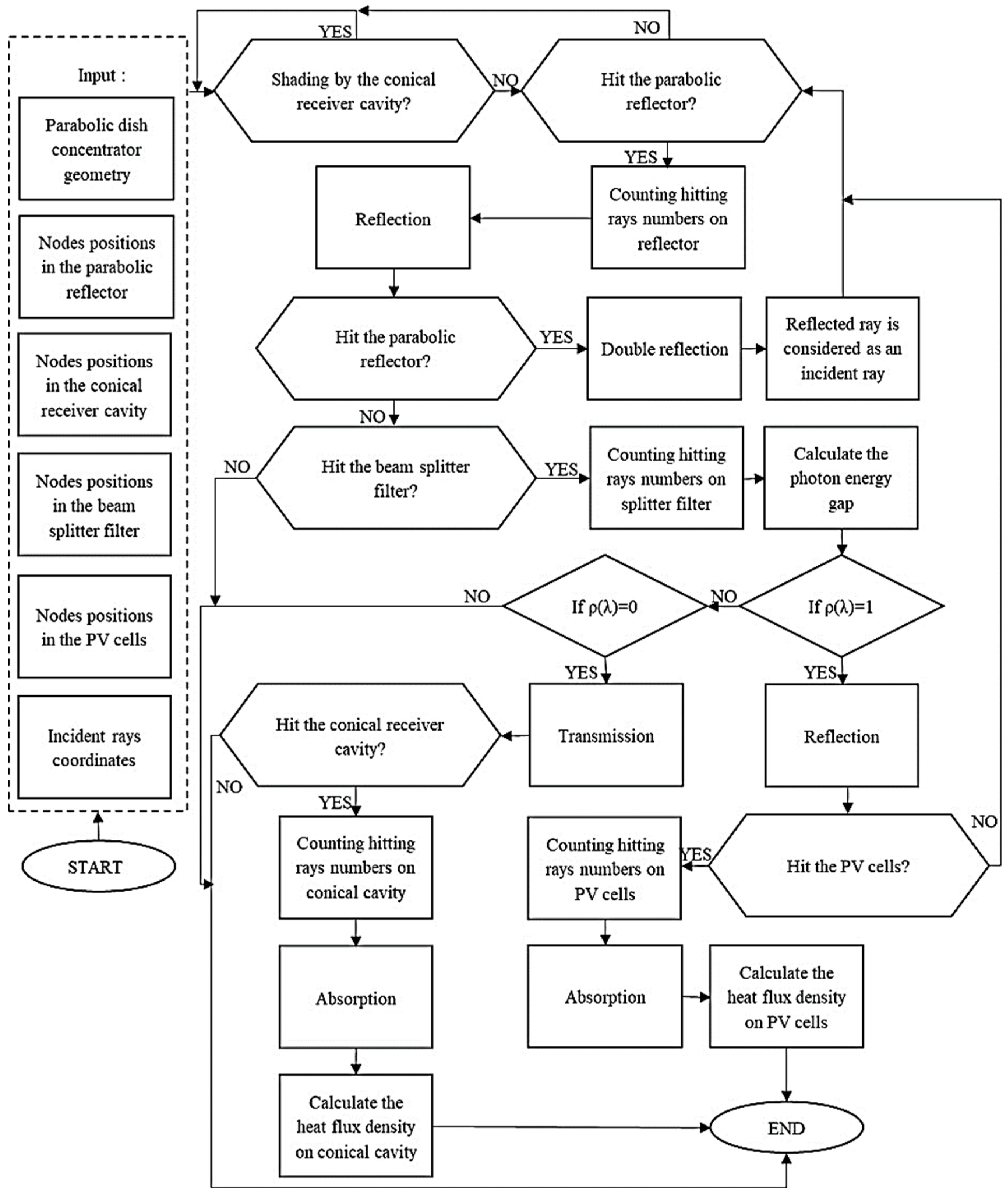
2.2.1. Optical RT 3D-4R Method
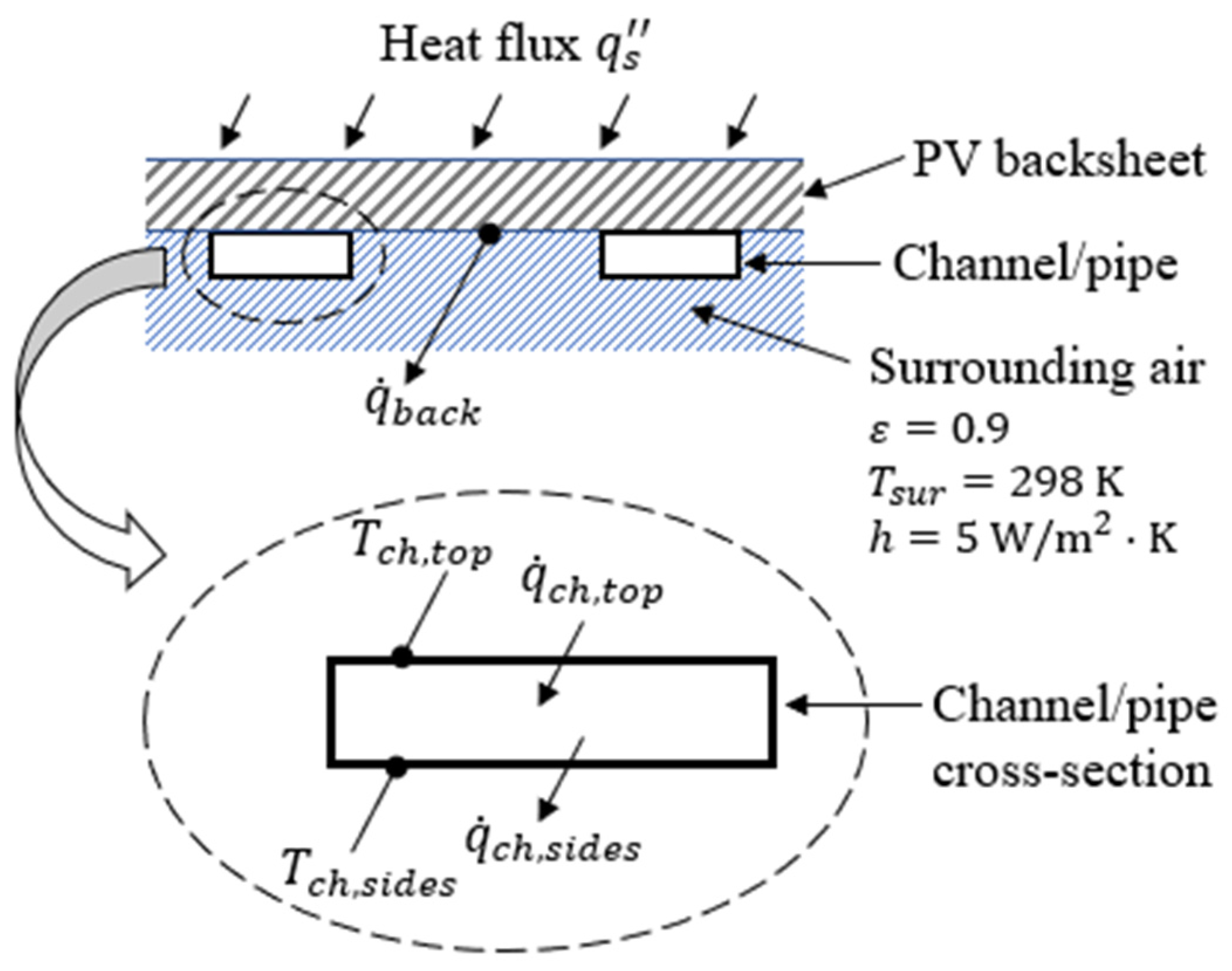
2.2.2. Heat Transfer Modeling of the PV and Conical Cavity Receivers
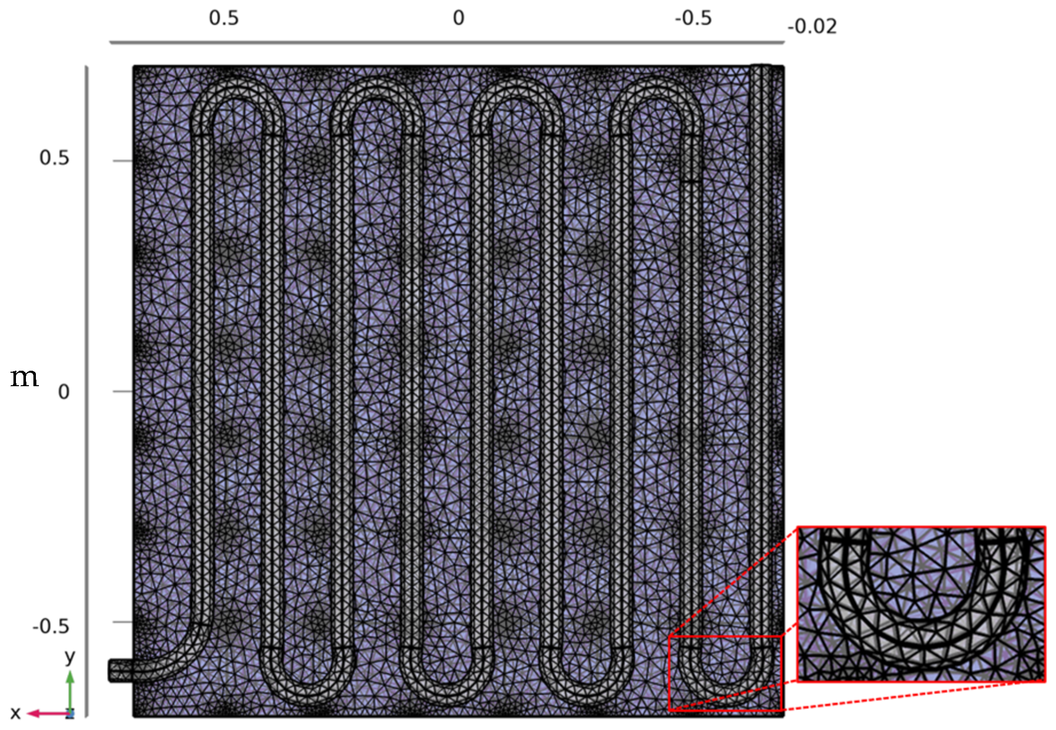
Heat Transfer on Sinusoidal Coiled Tube of the PV Cells Panels
3. Results of Simulation Methods
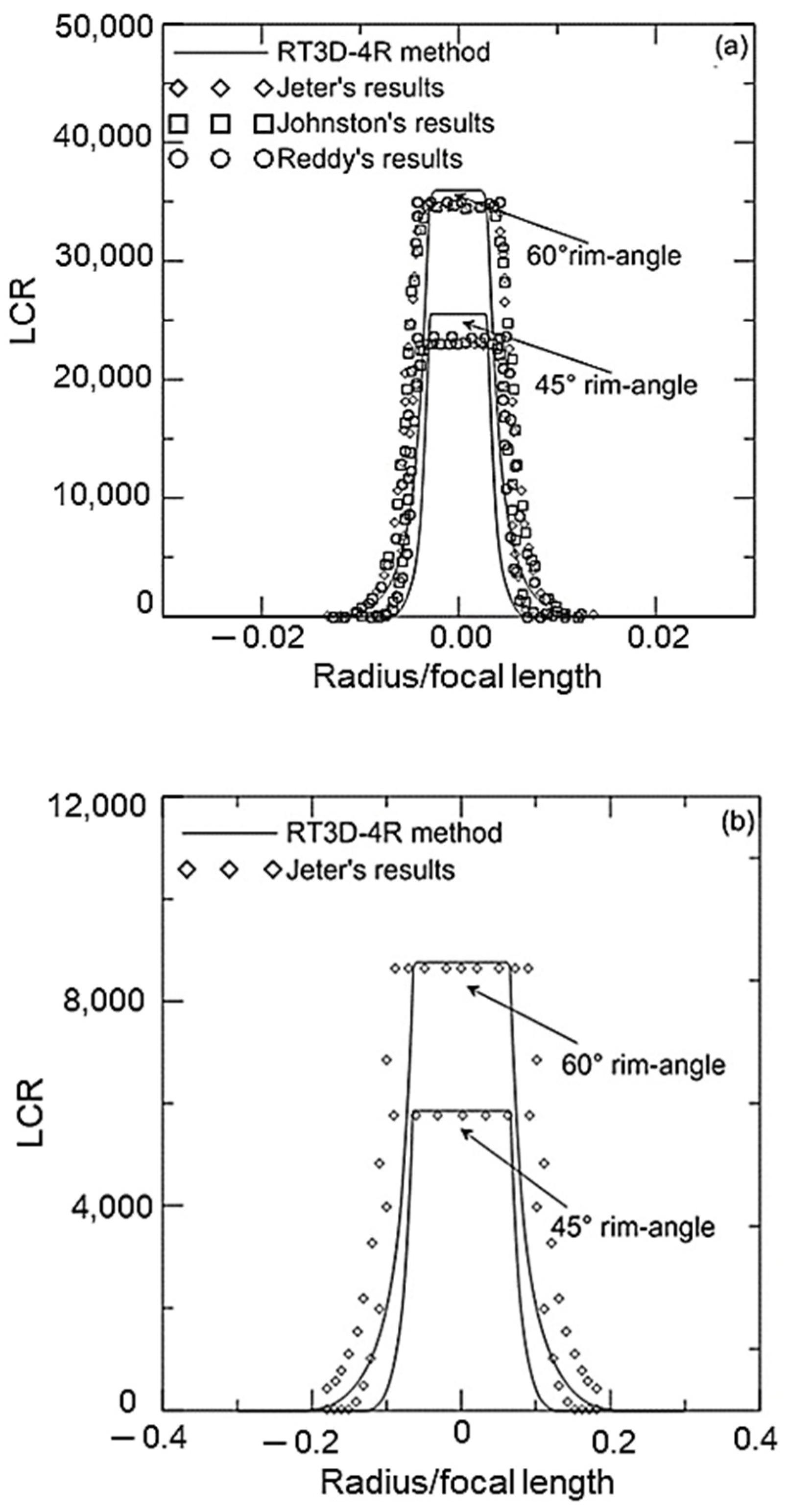
3.1. Validation of the RT3D-4R Technique
- Focal distance: = 1 m;
- Rim angle: 45° and 60°;
- Sun subtend disk angle: = 16′ and 32′;
- Solar irradiance: .
3.2. Hybrid Parabolic Dish Collector Using Spectral Beam Splitter Technology
3.2.1. Beam Splitter Filter and Concentrated Solar Rays
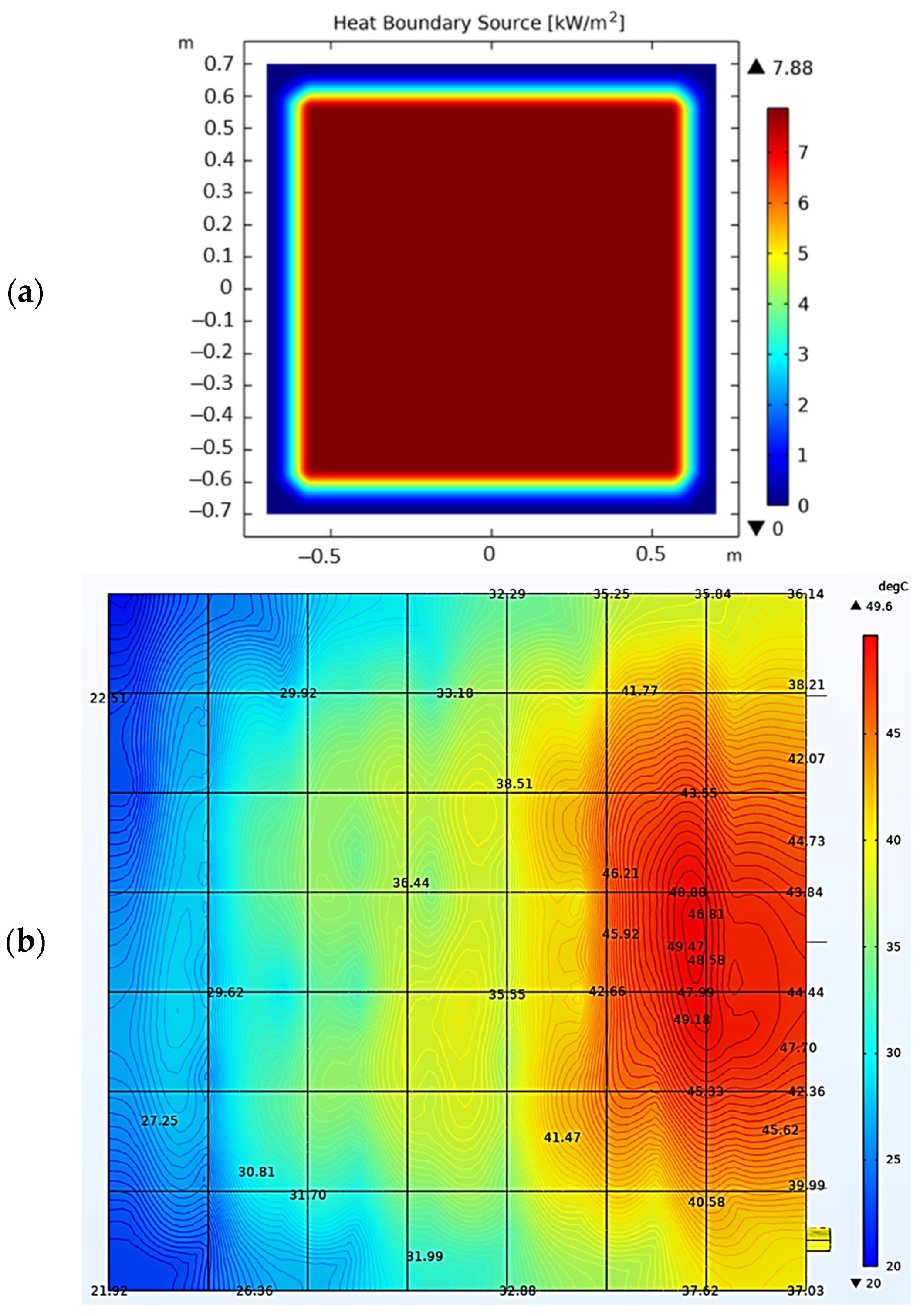
3.2.2. Concentration Ratio and Temperature Distribution on the CCR
3.2.3. Heat Load and Temperature Distribution of the Solar Cells with Conventional Coiled Pipe
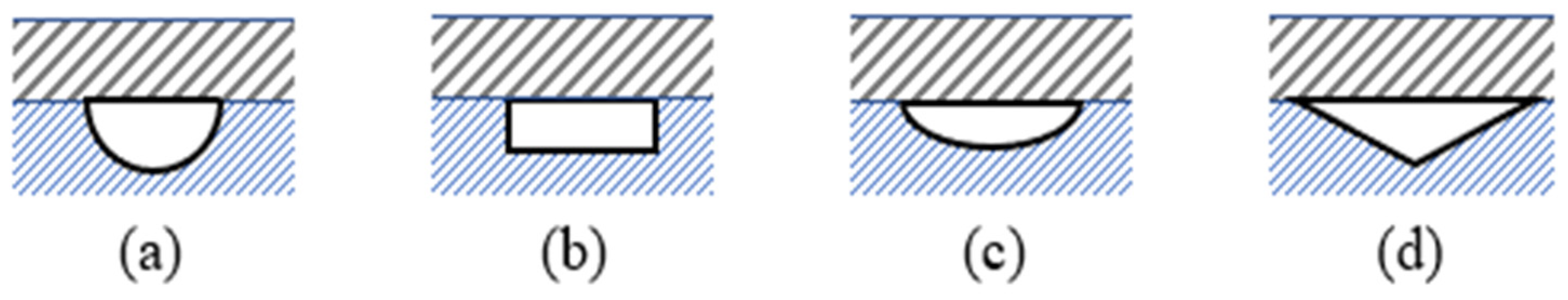
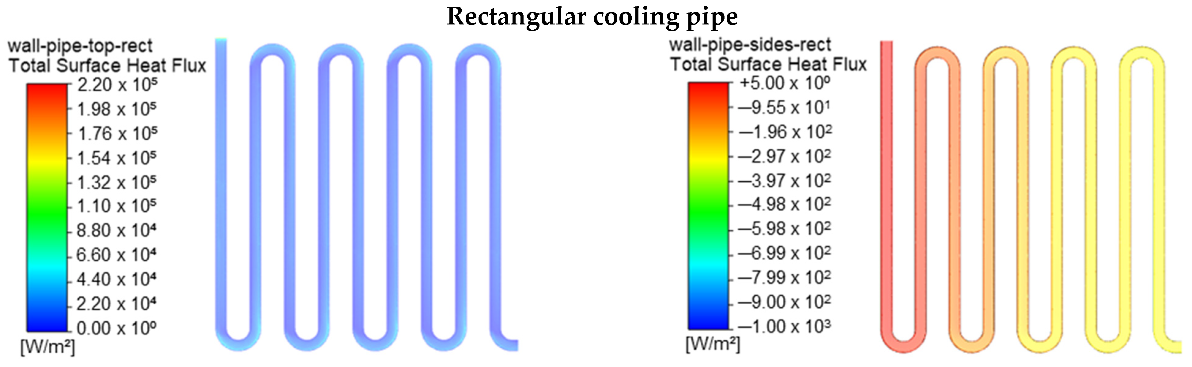
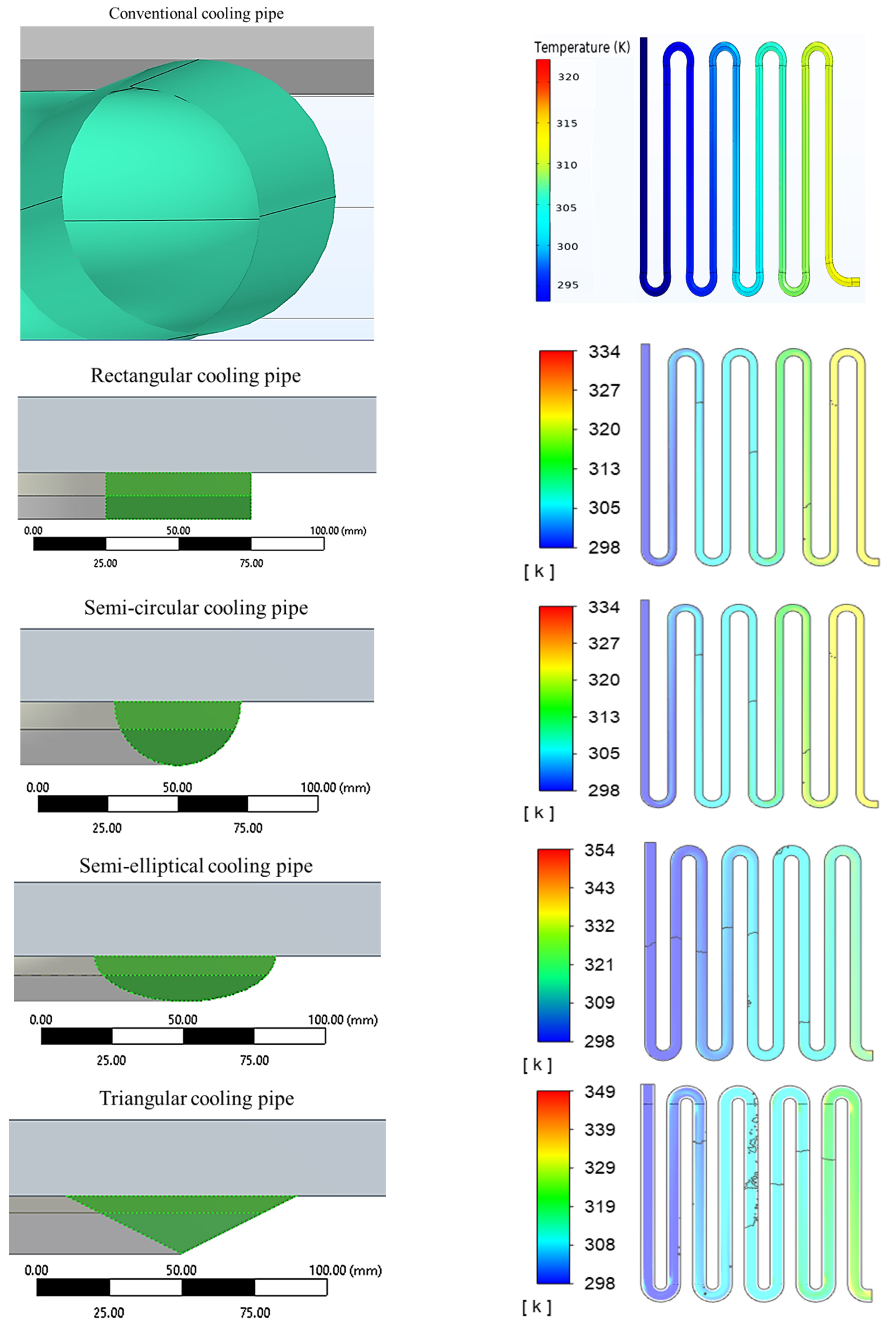
3.2.4. Heat Load and Temperature Distribution of the Solar Cells with Different Coiled Pipe Forms
4. Comparison of Previous Similar Studies
5. Discussion
- The triangular cross-section shape resulted in the largest increment in temperature, in other words the maximum useful gain energy, recording the highest increment in temperature of 30.3 °C. The triangular cross-section shape recorded the fastest rate at which heat was transferred to the water flow in the serpentine-shape embedded cooling pipes.
- The same cooling pipe design, i.e., the triangular cross-section shape, recorded the lowest heat sink temperature resulting in the highest heat transfer rate to the cooling water flow of 11.834 kW.
6. Conclusions
- First, the optical validity of the RT3D-4R method has been approved to simulate the performance of the parabolic dish concentrator for two case studies (flat receiver and conical receiver).
- Second, the thermo-optical characteristics of the proposed PV/PDC-CCR-BSF system have been optimized and performed.
- Third, the thermo-optical performance of the proposed system for four different cooling pipe cross-sections of serpentine-shape embedded water-cooling pipes have been numerically simulated and the results compared against those of the conventional circular cross-section cooling pipe placed underneath the PV panel rear sheet. The outcomes showed that:
- ○
- The heat sinks and the water-cooling pipe’s interface width determine the heat flux pattern and transfer rates in a comparative manner.
- ○
- The water temperature increment between the inlet and outlet ports of the embedded serpentine water-cooling pipe is equal to 28.6 °C for the rectangular cross-section cooling pipe, 28.2 °C for the semicircular cross-section cooling pipe, 29.9 °C for the semi-elliptical cross-section cooling pipe and 30.3 °C for the triangular cross-section cooling pipe.
- ○
- Amongst the four different cross-sections, the triangle cross-section is found to have a greater heat extraction capability than the other cross-sections. It gives the highest heat rate to the cooling water, the lowest back-sheet temperature and heat flux ( −446 W), yielding the highest amount of removed thermal power in the water flow medium.
- ○
- The outcomes demonstrated that the traditional cooling pipe, which is also placed underneath the solar cells, has poorer cooling performance in comparison with the four serpentine-shape embedded water-cooling configurations.
Author Contributions
Funding
Informed Consent Statement
Data Availability Statement
Acknowledgments
Conflicts of Interest
Nomenclature
| English alphabets | Units | Greek symbols | Units | ||
| D | Concentrated solar density | [kW/m2] | α | Absorptivity | - |
| ds | Surface (differential) of the collector | [m2] | θ | Angle | [rad] |
| dS | Size (differential) of the sunspot | [m2] | ρ | Reflectivity | - |
| E | Incident solar density | [kWh/m2] | σ | Solar angle | [Arcminutes] |
| f | Focal length | [m] | λ | Solar ray wavelength | [m] |
| G | Grid number | - | Subscripts | ||
| Q | Solar flux | [kW/m2] | c | Collector | |
| Thermal power | [W] | cr | Center receiver | ||
| T | Temperature | [°K] | i | Incidence | |
| Abbreviations | max | Maximum | |||
| DNI | Direct Solar Irradiance | min | Minimum | ||
| CSD | Concentrated Solar Density | op | Opening | ||
| RT3D-4R | Ray-Tracing 3Dimensions-4Rays | r | Receiver | ||
| BSF | Beam Splitter Filter | rim | Rim | ||
| TBT | Thiophene-Benzothiazole | s | Solar | ||
| EVA | Ethylene Vinyl Acetate | sc | Solar cell | ||
| PV | Photovoltaic | sf | Splitter filter | ||
| UV | Ultraviolet | g | Gap | ||
References
- Ju, X.; Xu, C.; Liao, Z.; Du, X.; Wei, G.; Wang, Z.; Yang, Y. A review of concentrated photovoltaic-thermal (CPVT) hybrid solar systems with waste heat recovery (WHR). Sci. Bull. 2017, 62, 1388–1426. [Google Scholar]
- Daneshazarian, R.; Cuce, E.; Cuce, P.M.; Sher, F. Concentrating photovoltaic thermal (CPVT) collectors and systems: Theory, performance assessment and applications. Renew. Sustain. Energy Rev. 2018, 81, 473–492. [Google Scholar]
- Mathew, G.; Pandey, A.K.; Nasrudin, A.R.; Tyagi, V.V.; Syed, S.; Saidur, R. Concentrated photovoltaic thermal systems: A component-by-component view on the developments in the design, heat transfer medium and applications. Energy Convers. Manag. 2019, 186, 15–41. [Google Scholar]
- Mojiri, A.; Taylor, R.; Thomsen, E.; Rosengarten, G. Spectral beam splitting for efficient conversion of solar energy—A review. Renew. Sustain. Energy Rev. 2013, 28, 654–663. [Google Scholar] [CrossRef]
- Imenes, A.G.; Mills, D.R. Spectral beam splitting technology for increased conversion efficiency in solar concentrating systems: A review. Sol. Energy Mater. Sol. Cells 2004, 84, 19–69. [Google Scholar] [CrossRef]
- Huang, G.; Curt, S.R.; Wang, K.; Markides, C.N. Challenges and opportunities for nanomaterials in spectral splitting for high-performance hybrid solar photovoltaic-thermal applications: A review. Nano Mater. Sci. 2020, 3, 183–203. [Google Scholar]
- Sahu, S.K.; Kopalakrishnaswami, A.S.; Natarajan, S.K. Historical overview of power generation in solar parabolic dish collector system. Environ. Sci. Pollut. Res. 2022, 29, 64404–64446. [Google Scholar]
- Jiang, S.; Chen, Z.; Peng, H. Three-dimension optical model of two-stage reflective spectral beam spliting concentrating PV system. Acta Energiae Solaris Sin. 2009, 30, 1188–1193. [Google Scholar]
- Jiang, S.; Hu, P.; Mo, S.; Chen, Z. Optical modeling for a two-stage parabolic trough concentrating photovoltaic/thermal system using spectral beam splitting technology. Sol. Energy Mater. Sol. Cells 2010, 94, 1686–1696. [Google Scholar] [CrossRef]
- Jiang, S.; Wang, G.; Hu, P.; Chen, Z.; Jia, L. The Design of Beam Splitter for Two-Stage Reflective Spectral Beam Splitting Concentrating PV/thermal System. In Proceedings of the Asia-Pacific Power and Energy Engineering Conference, IEEE 2011, Wuhan, China, 25–28 March 2011. [Google Scholar]
- Shou, C.-H.; Luo, Z.-Y.; Wang, T.; Shen, W.-D.; Gary, R.; Wang, C.; Ni, M.-J.; Cen, K.-F. A Dielectric Multilayer Filter for Combining Photovoltaics with a Stirling Engine for Improvement of the Efficiency of Solar Electricity Generation. Chin. Phys. Lett. 2011, 28, 128–402. [Google Scholar] [CrossRef]
- Wang, G.; Yao, Y.; Chen, Z.; Hu, P. Thermodynamic and optical analyses of a hybrid solar CPV/T system with high solar concentrating uniformity based on spectral beam splitting technology. Energy 2019, 166, 256–266. [Google Scholar] [CrossRef]
- Tyagi, V.V.; Kaushik, S.C.; Tyagi, S.K. Advancement in solar photovoltaic/thermal (PV/T) hybrid collector technology. Renew. Sustain. Energy Rev. 2012, 16, 1383–1398. [Google Scholar] [CrossRef]
- Sultan, S.M.; Efzan, M.N.E. Review on recent Photovoltaic/Thermal (PV/T) technology advances and applications. Sol. Energy 2018, 173, 939–954. [Google Scholar] [CrossRef]
- Lupu, A.G.; Homutescu, V.M.; Balanescu, D.T.; Popescu, A. A review of solar photovoltaic systems cooling technologies. In Proceedings of the 8th International Conference on Advanced Concepts in Mechanical Engineering, Iasi, Romania, 7–8 June 2018. [Google Scholar]
- Papis-Frączek, K.; Sornek, K. A Review on Heat Extraction Devices for CPVT Systems with Active Liquid Cooling. Energies 2022, 15, 6123. [Google Scholar] [CrossRef]
- Akbarzadeh, A.; Wadowski, T. Heat pipe-based cooling systems for photovoltaic cells under concentrated solar radiation. Appl. Therm. Eng. 1996, 16, 81–87. [Google Scholar] [CrossRef]
- Mittelman, G.; Kribus, A.; Dayan, A. Solar cooling with concentrating photovoltaic/thermal (CPVT) systems. Energy Convers. Manag. 2007, 48, 2481–2490. [Google Scholar] [CrossRef]
- Mittelman, G.; Kribus, A.; Mouchtar, O.; Dayan, A. Water desalination with concentrating photovoltaic/thermal (CPVT) systems. Sol. Energy 2009, 83, 1322–1334. [Google Scholar] [CrossRef]
- Othman, M.Y.; Yatim, B.; Sopian, K.; Bakar, M.N. Performance analysis of a double-pass photovoltaic/thermal (PV/T) solar collector with CPC and fins. Renew. Energy 2005, 30, 2005–2017. [Google Scholar] [CrossRef]
- Hedayatizadeh, M.; Ajabshirchi, Y.; Sarhaddi, F.; Safavinejad, A.; Farahat, S.; Chaji, H. Thermal and Electrical Assessment of an Integrated Solar Photovoltaic Thermal (PV/T) Water Collector Equipped with a Compound Parabolic Concentrator (CPC). Int. J. Green Energy 2013, 10, 494–522. [Google Scholar] [CrossRef]
- He, Y.; Xiao, L.; Li, L. Theoretical and experimental study on the application of diffuse-reflection concentrators in PV/T solar system. Int. J. Energy Res. 2016, 40, 963–970. [Google Scholar] [CrossRef]
- Meng, X.; Xia, X.; Sun, C.; Li, Y.; Li, X. A novel free-form Cassegrain concentrator for PV/T combining utilization. Sol. Energy 2016, 135, 864–873. [Google Scholar] [CrossRef]
- Koronaki, I.P.; Nitsas, M.T. Experimental and theoretical performance investigation of asymmetric photovoltaic/thermal hybrid solar collectors connected in series. Renew. Energy 2018, 118, 654–672. [Google Scholar] [CrossRef]
- Wang, K.; Pantaleo, A.M.; Herrando, M.; Pesmazoglou, I.; Franchetti, B.M.; Markides, C.N. Thermoeconomic assessment of a spectral splitting hybrid PV-T system in dairy farms for combined heat and power. In Proceedings of the 32nd International Conference on Efficiency, Cost, Optimization, Simulation and Environmental Impact of Energy Systems (ECOS), Wroclaw, Portland, 23–28 June 2019; pp. 23–28. [Google Scholar]
- Felsberger, R.; Buchroithner, A.; Gerl, B.; Wegleiter, H. Conversion and Testing of a Solar Thermal Parabolic Trough Collector for CPV-T Application. Energies 2020, 13, 6142. [Google Scholar] [CrossRef]
- Renno, C. Theoretical and Experimental Evaluation of the Working Fluid Temperature Levels in a CPV/T System. Energies 2020, 13, 3077. [Google Scholar] [CrossRef]
- Renno, C.; Petito, F.; D’Agostino, D.; Minichiello, F. Modeling of a CPV/T-ORC Combined System Adopted for an Industrial User. Energies 2020, 13, 3476. [Google Scholar] [CrossRef]
- Nasseriyan, P.; Afzali Gorouh, H.; Gomes, J.; Cabral, D.; Salmanzadeh, M.; Lehmann, T.; Hayati, A. Numerical and Experimental Study of an Asymmetric CPC-PVT Solar Collector. Energies 2020, 13, 1669. [Google Scholar] [CrossRef]
- Gakkhar, N.; Soni, M.S.; Jakhar, S. Experimental and theoretical analysis of hybrid concentrated photovoltaic/thermal system using parabolic trough collector. Appl. Therm. Eng. 2020, 171, 115069. [Google Scholar] [CrossRef]
- Ustaoglu, A.; Ozbey, U.; Torlaklı, H. Numerical investigation of concentrating photovoltaic/thermal (CPV/T) system using Compound Hyperbolic–Trumpet, V-trough and Compound Parabolic Concentrators. Renew. Energy 2020, 152, 1192–1208. [Google Scholar] [CrossRef]
- Lin, L.; Tian, Y.; Luo, Y.; Chen, C.; Jiang, L. A novel solar system integrating concentrating photovoltaic thermal collectors and variable effect absorption chiller for flexible co-generation of electricity and cooling. Energy Convers. Manag. 2020, 206, 112506. [Google Scholar] [CrossRef]
- Gomaa, M.R.; Al-Dhaifallah, M.; Alahmer, A.; Rezk, H. Design, Modeling, and Experimental Investigation of Active Water Cooling Concentrating Photovoltaic System. Sustainability 2020, 12, 5392. [Google Scholar] [CrossRef]
- Cabral, D.; Gomes, J.; Hayati, A.; Karlsson, B. Experimental investigation of a CPVT collector coupled with a wedge PVT receiver. Sol. Energy 2021, 215, 335–345. [Google Scholar] [CrossRef]
- Han, X.; Tu, L.; Sun, Y. A spectrally splitting concentrating PV/T system using combined absorption optical filter and linear Fresnel reflector concentrator. Sol. Energy 2021, 223, 168–181. [Google Scholar] [CrossRef]
- Gorouh, H.A.; Salmanzadeh, M.; Nasseriyan, P.; Hayati, A.; Cabral, D.; Gomes, J.; Karlsson, B. Thermal modelling and experimental evaluation of a novel concentrating photovoltaic thermal collector (CPVT) with parabolic concentrator. Renew. Energy 2022, 181, 535–553. [Google Scholar] [CrossRef]
- Howard, D.; Harley, R.G. Modeling of Dish-Stirling Solar Thermal Power Generation. In Proceedings of the IEEE PES General Meeting, Minneapolis, MN, USA, 25–29 July 2010; pp. 1–7. [Google Scholar]
- Fraser, P.R. Stirling Dish System Performance Prediction Model. Master’s Thesis, University of Wisconsin-Madison, Madison, WI, USA, 2008. [Google Scholar]
- Noor, N.; Muneer, S. Concentrating Solar Power (CSP) and Its Prospect in Bangladesh. In Proceedings of the 2009 1st International Conference on the Developements in Renewable Energy Technology (ICDRET), Dhaka, Bangladesh, 17–19 December 2009; 2009; pp. 1–5. [Google Scholar]
- Stine, W.B.; Diver, R.B. A Compendium of Solar Dish/Stirling Technology; Sandia National Laboratories, Albuquerque New Mexico 87185 and Livermore, California 94550, For the United States Department of Energy: Albuquerque, NM, USA, 1994. [Google Scholar]
- Geyer, M.A.; Stine, W.B. Power from the Sun. 2001. Available online: http://powerfromthesun.net/ (accessed on 24 December 2023).
- Gaith, F.; Taher, M.; Fahad, G. Performance Analysis of a Single Cell-Ultra-High Concentration Photovoltaic Thermal Module Based on Pin-Fins Cooling Microchannel. Int. J. Energy Res. 2021, 46, 2947–2969. [Google Scholar]
- Soteris, A.K. Solar thermal collectors and applications. Prog. Energy Combust. Sci. 2004, 30, 231–295. [Google Scholar]
- Li, H.; Huang, W.; Huang, F.; Hu, P.; Chen, Z. Optical analysis and optimization of parabolic dish solar concentrator with a cavity receiver. Sol. Energy 2013, 92, 288–297. [Google Scholar] [CrossRef]
- Wang, F.; Lin, R.; Liu, B.; Tan, H.; Shuai, Y. Optical efficiency analysis of cylindrical cavity receiver with bottom surface convex. Sol. Energy 2013, 90, 195–204. [Google Scholar] [CrossRef]
- Daabo, A.M.; Mahmoud, S.; Al-Dadah, R.K. The optical efficiency of three different geometries of a small-scale cavity receiver for concentrated solar applications. Appl. Energy 2016, 179, 1081–1096. [Google Scholar] [CrossRef]
- Daabo, A.M.; Mahmoud, S.; Al-Dadah, R.K. The effect of receiver geometry on the optical performance of a small-scale solar cavity receiver for parabolic dish applications. Energy 2016, 114, 513–525. [Google Scholar] [CrossRef]
- Shuai, Y.; Xia, X.-L.; Tan, H.-P. Radiation performance of dish solar concentrator/cavity receiver systems. Sol. Energy 2008, 82, 13–21. [Google Scholar] [CrossRef]
- Shuai, Y.; Xia, X.-L.; Tan, H.-P. Numerical Study of Radiation Characteristics in a Dish Solar Collector System. J. Sol. Energy Eng. 2008, 130, 021001. [Google Scholar] [CrossRef]
- Shuai, Y.; Xia, X.-L.; Tan, H.-P. Numerical simulation and experiment research of radiation performance in a dish solar collector system. Front. Energy Power Eng. China 2010, 4, 488–495. [Google Scholar] [CrossRef]
- Li, S.; Xu, G.; Luo, X.; Quan, Y.; Ge, Y. Optical performance of a solar dish concentrator/receiver system: Influence of geometrical and surface properties of cavity receiver. Energy 2016, 113, 95–107. [Google Scholar] [CrossRef]
- Reddy, K.S.; Natarajan, S.K.; Veershetty, G. Experimental performance investigation of modified cavity receiver with fuzzy focal solar dish concentrator. Renew. Energy 2015, 74, 148–157. [Google Scholar] [CrossRef]
- Johnston, G. Focal region measurements of the 20 m2 tiled dish at the Australian National University. Sol. Energy 1998, 63, 117–124. [Google Scholar] [CrossRef]
- Houcine, A.; Maatallah, T.; Saeed, F. Optothermal characterization of a hybrid Photovoltaic/Parabolic Dish Concentrator coupled with conical cavity receiver using beam splitter for steam and electrical power generation. Int. J. Energy Res. 2022, 46, 12341–12361. [Google Scholar] [CrossRef]
- Good, C. Environmental impact assessments of hybrid photovoltaic-thermal (PV/T) systems—A review. Renew. Sustain. Energy Rev. 2015, 55, 234–235. [Google Scholar] [CrossRef]
- Sreekumar, S.; Shah, N.; Mondol, J.; Hewitt, N.; Chakrabarti, S. Numerical Investigation and Feasibility Study on MXene/Water Nanofluid Based Photovoltaic/thermal System. Clean. Energy Syst. 2022, 103, 504–515. [Google Scholar] [CrossRef]
- Zenhäusern, D.; Bamberger, E.; Baggenstos, A.; Häberle, A. PVT Wrap-Up: Energy Systems with Photovoltaic-Thermal Solar Collectors. In Proceedings of the ISES Solar World Congress, Abu Dhabi, United Arab Emirates, 29 October–2 November 2017. [Google Scholar]
- Zeitouny, J.; Lalau, N.; Gordon, J.M.; Katz, E.A.; Flamant, G.; Dollet, A.; Vossier, A. Assessing high-temperature photovoltaic performance for solar hybrid power plants. Sol. Energy Mater. Sol. Cells 2018, 182, 61–67. [Google Scholar] [CrossRef]
- Ahliouati, M.; El Otmani, R.; Kandoussi, K.; Boutaous, M.H.; Louanate, A.; Louzazni, M.; Daya, A. Energetic and parametric studies of a basic hybrid collector (PV/T-Air) and a photovoltaic (PV) module for building applications: Performance analysis under El Jadida weather conditions. Mater. Sci. Energy Technol. 2023, 6, 267–281. [Google Scholar] [CrossRef]
- Alzaabi, A.A.; Badawiyeh, N.K.; Hantoush, H.O.; Hamid, A.K. Electrical/thermal performance of hybrid PV/T system in Sharjah, UAE. Int. J. Smart Grid Clean Energy 2014, 3, 385–389. [Google Scholar] [CrossRef]
- McIntosh, K.; Cotsell, J.; Cumpston, J.; Norris, A.; Powell, N.; Ketola, B. An optical comparison of silicone and EVA encapsulants for conventional silicon PV modules: A ray-tracing study. In Proceedings of the 34th IEEE Photovoltaic Specialists Conference, Philadelphia, PA, USA, 7–12 June 2009. [Google Scholar]
- DuPont Tedlar PVF General Properties. 2014. Available online: http://www.dupont.com/content/dam/dupont/products-and-services/membranes-and-films/pvffilms/documents/DEC_Tedlar_GeneralProperties.pdf (accessed on 1 September 2016).
- Ju, X.; Wang, Z.; Flamant, G.; Li, P.; Zhao, W. Numerical analysis and optimization of a spectrum splitting concentration photovoltaic-thermoelectric hybrid system. Sol. Energy 2012, 86, 1941–1954. [Google Scholar] [CrossRef]
- Houcine, A.; Maatallah, T.; El Alimi, S.; Nasrallah, S.B. The Performance Study of Parabolic Trough Concentrator Using a New RT3D-4R Method. Int. J. Control. Theory Appl. 2016, 9, 133–139. [Google Scholar]
- Maatallah, T.; Houcine, A.; El Alimi, S.; Nasrallah, S.B. Optical modeling and investigation of sun tracking parabolic trough solar collector basing on Ray Tracing 3Dimensions-4Rays. Sustain. Cities Soc. 2017, 35, 786–798. [Google Scholar]
- Taher, M.; Ahlem, H.; Souheil, E.A.; Sassi, B.N. A novel solar concentrating system based on a fixed cylindrical reflector and tracking receiver. Renew. Energy 2018, 117, 85–107. [Google Scholar]
- Maatallah, T.; Ammar, R. Design, modeling, and optimization of a dual reflector parabolic trough concentration system. Int. J. Energy Res. 2020, 44, 3711–3723. [Google Scholar] [CrossRef]
- Evans, D. On the Performance of Cylindrical Parabolic Solar Concentrators with Flat Absorbers. Sol. Energy 1977, 19, 379–385. [Google Scholar] [CrossRef]
- Jeter, S.M. The distribution of concentrated solar radiation in paraboloidal collectors. J. Sol. Energy Eng. 1986, 108, 108–219. [Google Scholar] [CrossRef]
- Soteris, A.K.; Constantinos, C.N.; Christos, N.S. A comparative study of methods for estimating intercept factor of parabolic trough collectors. In Proceedings of the Engineering Applications of Neural Networks (EANN’96) Conference, London, UK, 17–19 June 1996. [Google Scholar]


| Item | Symbol | Values [m] | |
|---|---|---|---|
| Parabolic reflector | Aperture radius | wc | 2.5 |
| Focal length | f | 3 | |
| Conical cavity receiver | Upper radius | rmax | 0.1 |
| Lower radius | rmin | 0.05 | |
| Beam splitter | Aperture radius | wsf | 0.1 |
| Focal length | fs | 0.05 | |
| PV cells | Aperture width | wsc | 1.4 |
| Glass | EVA | Cell | Backsheet | |
|---|---|---|---|---|
| Material | Silica glass | Elvax 250 (28% VA, 25 MI) | polycrystalline cell | Thiophene-Benzothiazole |
| Width (m) | 1.4 | 1.4 | 0.2 | 1.4 |
| Length (m) | 1.4 | 1.4 | 0.2 | 1.4 |
| Thickness (m) | 0.0032 | 0.0017 | 0.0002 | 0.02 |
| Refractive index | 1.45 | 1.49 [61] | 4.052 | 1.46 [62] |
| Thermal conductivity (W/m K) | 1.83 | 0.15 | 60 | 0.15 |
| Specific heat capacity (J/Kg K) | 730 | 2090 | 320 | 1250 |
| Density (Kg/m3) | 2203 | 950 | 5323 | 1170 |
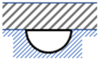
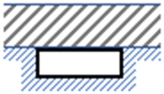
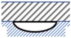
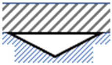
| No | Geometry | Dimensions | Width w (mm) | Perimeter * p (mm) | Depth d (mm) | Hydraulic Diameter Dh (mm) |
|---|---|---|---|---|---|---|
| 1. | 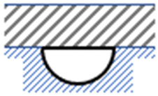 |  | 45.14 | 141.8 | 22.57 | 22.6 |
| 2. | 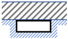 |  | 50.00 | 132.0 | 16.00 | 24.2 |
| 3. | 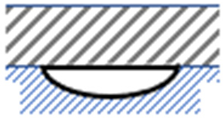 | 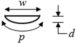 | 63.66 | 158.3 | 16.00 | 20.2 |
| 4. | 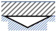 | 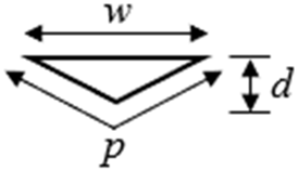 | 80.00 | 169.4 | 20.00 | 18.9 |
| Parameter | Value |
|---|---|
| Pipe wall material | Copper |
| Pipe wall thickness (mm) | 0.5 |
| Pipe inlet/outlet areas (m2) | 0.0008 |
| Pipe length (m) | 12.637 |
| Inlet temperature (K) | 298.0 |
| Inlet flow velocity (m/s) | 0.125 |
| Inlet mass flow rate (kg/s) | 0.10 |
| Air temperature (K) | 298.0 |
| Heat flux (W/m2) | 6400.0 |
| Material surface emissivity | 0.9 |
| Geometry | (K) | (°C) | (K) | (K) | (K) | (kW) | (W) | (W) | (kW) |
|---|---|---|---|---|---|---|---|---|---|
 | 326.2 | 28.2 | 341.28 | 311.93 | 344.76 | 11.690 | −136 | −855 | 11.491 |
 | 326.6 | 28.6 | 339.35 | 311.72 | 342.70 | 11.765 | −154 | −779 | 11.548 |
 | 327.9 | 29.9 | 334.65 | 312.10 | 337.60 | 11.941 | −149 | −603 | 11.730 |
 | 328.3 | 30.3 | 330.29 | 313.82 | 333.10 | 12.098 | −195 | −446 | 11.834 |
| Authors | Numerical/Experimental | Concentrator Solar System Device | Type of Cooling System | Optical Concentration Ratio | Heat Transfer Fluid | ΔT (°C) | Efficiencies/Electrical or Thermal Power | Main Outcomes/Milestones |
|---|---|---|---|---|---|---|---|---|
| Akbarzadeh et al. [17] | Numerical & experimental | One-axis tracked east-west parabolic trough concentrator | Thermosyphon external to the structure | 20 suns | Water & R-11 | 21 | Electrical power = 20.6 W | The performance improvement of the proposed concentrating solar system is caused by enhancement of the primary optical stage properties by the effectiveness of the cooling mechanism. |
| Othman et al. [20] | Numerical & experimental | Parabolic concentrator | Fins peripheral to the structure | 1.95 suns | Air | 18 |
| The surge in the cogeneration effectiveness of the system. |
| Hedayatiza-deh et al. [21] | Numerical | Compound parabolic concentrator | Duct external to the system | 2 suns | Water | 7.7 |
| The investigation of the thermal and electrical performance of the hybrid PV/T-system-based compound parabolic concentrator. |
| He et al. [22] | Experimental | Non-imaging-based-diffuse-reflection PV/T concentrator solar system | Channel exterior to the arrangement | ≤2 suns | Water | 41 | Average output electrical power = 22.9 W | The proposed optical design boosted the productivity of the CPV/T system. |
| Koronaki et al. [24] | Numerical & experimental | Compound parabolic concentrator | Duct external to the system | 1.414 suns | Water | 7.8 |
|
|
| Wang et al. [25] | Experimental | Parabolic trough concentrator | Channel external to the system | 1.25 suns | Water | 0–30 |
| Lower cell temperature by the implementation of a spectral beam splitter, higher steam production, and more significant hot water supply. |
| Felsberger et al. [26] | Numerical & experimental | Parabolic trough concentrator | Channel | 900 | Water/glycol | 20.5 |
| The potential to combine the simultaneous generation of both heat and electricity by retrofitting traditional parabolic collector which is typically only employed in thermal systems with multijunction solar cells. |
| Renno et al. [27,28] | Numerical & experimental | Parabolic trough concentrator | Channel | 100 | Water | 28–56 |
| When considering energy options, an integrated CPV/T-ORC system proves to be the best choice for a commercial consumer. |
| Nasserian et al. [29] | Numerical & experimental | Compound parabolic concentrator | Channel | 1.52 | Water | 35.1 |
| The improvement of the thermal and electrical production of a Solarus Power Collector. |
| Gakkhar et al. [30] | Numerical & experimental | Parabolic trough concentrator | Pipe | 6 | Water | 28.7 |
| The evaluation of the performance of hybrid system in terms of respective efficiencies. |
| Ustaoglu et al. [31] | Numerical | Compound hyperbolic trumpet concentrator | Pipe | 1.94 | Water | 1.2 |
| Offer the CPV solution’s benefits in order to attain a more affordable design and superior performance. |
| Lin et al. [32] | Numerical | Parabolic dish concentrator | Channel | 10 | Water | 30 |
| The suggested system provides variable cogeneration of electricity and cooling. |
| Gomaa et al. [33] | Numerical & experimental | Fresnel flat mirror concentrator | Pipe | 3 suns | Water | 8–13.5 |
| Both electrical and thermal efficiency was increased by raising the cooling water capacity in both setups. This maximized the heat recuperation from the photovoltaic module (PV). |
| Gabral et al. [34] | Experimental | Parabolic trough concentrator | Channel | 2 | Water | 25 |
| Moving the highest power of energy at normal incidence angles to more extreme incidence angles. |
| Hen et al. [35] | Mathematical | Flat mirror concentrator | Channel exterior to the system | 24 suns | Liquid | 23.9 |
| Enhancement of the optical behavior and overall system performance due to the optimized beam filter coating characteristics. |
| Gorouh et al. [36] | Numerical & experimental | Parabolic trough concentrator | Channel | 2.7 | Water | 40 |
| Finding the essential CPVT collector design parameters for additional improvements. |
| Present work | Numerical | Hybrid photovoltaic/parabolic dish concentrator | Variously sized and positioned channels that are incorporated onto the PV rear sheet | 6.4 suns | Water | 29–33 |
| PV module back sheet with 3D-printed and embedded channels of dissimilar cross-sections and positions with respect to the heat transfer source. |
Disclaimer/Publisher’s Note: The statements, opinions and data contained in all publications are solely those of the individual author(s) and contributor(s) and not of MDPI and/or the editor(s). MDPI and/or the editor(s) disclaim responsibility for any injury to people or property resulting from any ideas, methods, instructions or products referred to in the content. |
© 2024 by the authors. Licensee MDPI, Basel, Switzerland. This article is an open access article distributed under the terms and conditions of the Creative Commons Attribution (CC BY) license (https://creativecommons.org/licenses/by/4.0/).
Share and Cite
Maatallah, T.; Houcine, A.; Saeed, F.; Khan, S.; Ali, S. Simulated Performance Analysis of a Hybrid Water-Cooled Photovoltaic/Parabolic Dish Concentrator Coupled with Conical Cavity Receiver. Sustainability 2024, 16, 544. https://doi.org/10.3390/su16020544
Maatallah T, Houcine A, Saeed F, Khan S, Ali S. Simulated Performance Analysis of a Hybrid Water-Cooled Photovoltaic/Parabolic Dish Concentrator Coupled with Conical Cavity Receiver. Sustainability. 2024; 16(2):544. https://doi.org/10.3390/su16020544
Chicago/Turabian StyleMaatallah, Taher, Ahlem Houcine, Farooq Saeed, Sikandar Khan, and Sajid Ali. 2024. "Simulated Performance Analysis of a Hybrid Water-Cooled Photovoltaic/Parabolic Dish Concentrator Coupled with Conical Cavity Receiver" Sustainability 16, no. 2: 544. https://doi.org/10.3390/su16020544
APA StyleMaatallah, T., Houcine, A., Saeed, F., Khan, S., & Ali, S. (2024). Simulated Performance Analysis of a Hybrid Water-Cooled Photovoltaic/Parabolic Dish Concentrator Coupled with Conical Cavity Receiver. Sustainability, 16(2), 544. https://doi.org/10.3390/su16020544