Article

Research on Efficiency of Permanent-Magnet Synchronous Motor Based on Adaptive Algorithm of Fuzzy Control

1
College of General Aviation and Flight, Nanjing University of Aeronautics and Astronautics, Nanjing 210016, China
2
Nanjing Watt Electric Motors Corporation, Nanjing 211200, China
*
Authors to whom correspondence should be addressed.
Sustainability 2024, 16(3), 1253; https://doi.org/10.3390/su16031253
Submission received: 4 December 2023 / Revised: 18 January 2024 / Accepted: 25 January 2024 / Published: 1 February 2024
(This article belongs to the Section Energy Sustainability)

Abstract

:
In today’s world, energy is undoubtedly one of the most significant problems. As the global electricity consumption continues to increase, electric motors, which are widely used as power devices, account for an increasingly prominent proportion of the energy consumed. Motors now consume about 45% of the total electricity in the world (60% in China); therefore, improving motor efficiency has become an important way to achieve carbon emission reduction and sustainable development. The aim of this research was to devise a new strategy to reduce CO2 emissions other than by building green power factories, because even the building of green power factories produces a great deal of CO2 emissions, and improving motor efficiency to reduce CO2 emissions could contribute to sustainable development worldwide. However, the improvement of motor efficiency encounters challenges, such as nonlinearity and disturbances, which affect the motor performance and energy efficiency. To address this issue, this paper proposes a control algorithm for permanent-magnet synchronous motors (PMSMs) that is highly efficient and would be most widely used based on a fuzzy control adaptive forgetting factor. It aims to enhance the efficiency and accuracy of the online parameter estimation for the PMSM flux linkage, thereby achieving more precise and energy-efficient motor control. Firstly, the recursive least-squares parameter estimation algorithm is used to identify the parameters of the PMSM. This ensures that the parameter estimation values can be dynamically updated with data changes, adapting to the time-varying parameters. Secondly, the Padé approximation method is adopted, which is a method that does not depend on the motor hardware, to improve the accuracy of the linearized model of the motor. Finally, a control algorithm based on the fuzzy control adaptive forgetting factor algorithm is constructed on a physical experimental platform. A comparison of these results proves that the control technology under this algorithm provides a new energy-saving control strategy that can estimate the motor flux linkage parameters more accurately, help to reduce energy consumption, promote the use of clean energy, and achieve sustainable performance optimization.

1. Introduction

Permanent-magnet synchronous motors (PMSMs) have the advantages of high power efficiency, a small size, reliable performance, and a wide working speed range, which make them the first choice in many applications, not only in the fields of electric vehicles, unmanned aerial vehicles, precision machine tools, and industrial robots, but also in the fields of home electric appliances, air conditioners, building ventilation, and pumps and fans. PMSMs are widely used in almost every field of electrics. Due to their widespread use in every domain, research on the energy-saving control technology of PMSMs is of very high commercial and societal value.
There have been many studies on motor energy-saving technologies, with some aiming to improve the motor efficiency through motor hardware design changes and others aiming to improve the motor efficiency through motor control technology. The methods of hardware optimization are very clear: better winding materials, better motor ventilation structure designs, and the use of rare-earth materials, like neodymium iron boron (NdFeB), to increase the magnetic flux density. There are two main energy-saving control strategies to improve the PMSM efficiency from the controlling point: the motor loss model and the input-power-searching model [1,2,3,4,5,6,7,8,9]. The loss model controls the motor through the optimization of the set values of the magnetic flux (or winding current and other electric data), which are calculated through mathematical methods. It has the advantages of a clear mathematical concept, clear physical sense, and fast response speed. However, it also has some disadvantages, like the difficulty in building the appropriate objective function. It is also limited by the building of an appropriate loss model and the obtainment of the on-time parameters, as these parameters change very quickly when the motor’s winding temperature, current, speed, on-load torque, or working environment change. If the tracking, measurement, and obtainment of the parameters are not performed on time, the control effectiveness of the loss model will be reduced, which will cause the motor to work at sub-optimal efficiency. In addition, the building of an accurate mathematical model will make the objective function very complex, the difficulty of the calculation will become much larger, and the final control effectiveness will be weakened. Ma [10] conducted research on an energy-saving control strategy for induction motors. This method was based on a genetic algorithm and compensated for equal iron losses at different speeds. Additionally, they analyzed and presented strategies to ensure the effectiveness of the efficiency-optimizing control regarding the motor’s dynamic responses. Sun [11] proposed different optimization processes to meet multiple optimization objectives simultaneously. The effectiveness of the optimization of the core loss and PM eddy loss was validated and the temperature rise was suppressed effectively. Zhang [12] proved the motor control system’s convex property based on a PMSM loss model through a multi-objective optimization algorithm. The author also proved that the electric vehicle’s efficiency could be improved via the optimization of the time torque distribution.
The input-power-search-based control strategy is an optimization technique that does not require motor parameters and models, in contrast to loss models. The control system monitors the motor input power in real time according to the motor operation status, and it adjusts the motor stator’s magnetic chain synchronously so that the motor control system operates at the lowest loss operating point. The search method control strategy is in fact an optimization process, and it monitors the motor input power at the DC side of the inverter and eventually reaches convergence through a continuous optimization search. However, the input power search technique requires highly accurate input power monitoring, especially in the case of light-load motors with very low motor excitation fluxes and flat power changes near the optimal efficiency operating point. This places high demands on the accuracy of the motor power detection and on noise suppression (permanent-magnet motors have high electromagnetic noise at low speeds). The input power search control strategy has a long convergence time and is not suitable for applications involving frequent starting and braking. The algorithm causes torque pulsations during the search process, especially when the input power function is smooth near the minimum value, which can easily cause system oscillations and instability. In addition, the search method needs to detect the power accurately, which imposes substantial hardware requirements for the system, and the realization of the system has some difficulties. In recent years, the rapid development of intelligent control algorithms has provided new ideas for energy-saving motor control. Some scholars have proposed the optimization of the input power search algorithm based on fuzzy control when the motor is running under light loads, and the use of fuzzy controllers to dynamically adjust the excitation component of the stator current can expedite the convergence speed of the search method. Gautam [13] studied the optimal power management strategy to improve the motor efficiency. A novel hybrid online DC minimum power fuzzy search efficiency optimization control algorithm was proposed by Zhang [14], which contains a novel proportional factor extraction strategy. Compared with other fuzzy search controls, this strategy can obtain the corresponding proportionality factors of input and output variables for each steady state condition of the motor online, without simulation calculation, solving the problem of the system oscillating at the optimal point of efficiency. Sheng [15] improved the operating efficiency of a permanent-magnet motor motion system in an urban rail system by means of an optimal magnetic chain/speed control strategy and an efficiency-optimized instantaneous power control strategy, as well as harmonic suppression techniques.
These previous studies have demonstrated effectiveness in improving the motor efficiency, but the motor in any system does not work at a constant speed. With a constant working temperature, its working process is a nonlinear process; during this process, the motor’s speed, input power, resistance, and output torques are always changing. Therefore, the online parameters are always changing. Most previous researches has utilized either the “loss model” or the “input-power-searching model”. Some have focused on mixed or combined applications. While these works are very helpful in the study of motor efficiency improvement, but they do not consider motor efficiency improvement through the more accurate control of magnet chains’ nonlinear parameters. They also have in common that any efficiency improvement can be treated as a method of loss reduction, and the best way to improve the motor’s working efficiency is to implement loss reduction throughout the whole motor operation process [16,17,18,19]. This necessitates the consideration of not only one working point—for example, the rated power point—but all points, from the start to the end. It also requires that the motor control algorithm can change its control strategy according to the online parameter changes. The issue of how to make control algorithms adaptable to a motor’s different working conditions, with better working efficiency at each condition, has become an important research direction in motor control technology.
Compared to the existing literature, the main contributions of this paper are as follows:
(1)
An algorithm is proposed to improve the PMSM’s online magnet chain values by adjusting the forgetting factors based on fuzzy self-adaption;
(2)
The recursive least-squares parameter estimation algorithm is adopted to identify the parameters of the PMSM; this ensures that the parameter estimation values can be dynamically updated with data changes, adapting to the time-varying parameters;
(3)
A control algorithm based on the fuzzy control adaptive forgetting factor algorithm is constructed on a physical experimental platform.

2. PMSM Control Model Building

2.1. Building Field-Oriented Control (FOC) for PMSM

In order to control the PMSM, we need to build field-oriented control (FOC) into the PMSM; before we build FOC, it is necessary to build the PMSM’s dq synchronous rotation coordinate system, as shown in Figure 1.
The shaft whose direction is the same as the motor rotor’s running direction is defined as shaft d, the shaft that is in an orthogonal direction is defined as shaft q, and the coordinate system that consists of shafts dq is the PMSM’s synchronous rotation coordinate system.
Through building a dq rotating rectangular coordinate system on the rotor magnet, the PMSM’s voltage vector equation is obtained:
{ V q = R 1 i q + p L q i q + ω r ( L d i d + ψ f ) V d = R 1 i d + p ( L d i d + ψ f ) ω r L q i q
where Vq, Vd are the PMSM’s dq axis voltage component; id, iq are the dq axis current component; Ld, Lq are the PMSM’s dq axis inductance; R1 is the phase resistance of the stator winding; ψ f is the permanent magnet flux linkage; and ω r is the angle speed of the rotor. The magnet torque produced by the PMSM is
T e = p p ( ψ f i q + ( L d L q ) i d i q )
Here, p p is the motor pole pair. As we use a surface-mounted magnet motor [11], there is no salient effect, so we can control the exciting current with the above equation = 0, and the magnet torque can be simplified to be
T e = p p ψ f i q
As one of the normal control methods for PMSMs, the basic concept of field-oriented control (FOC) is to address the resolution of the motor’s 3-phase alternating current (AC) voltage to Vd and Vq, and to address the resolution of the AC current to direct current (DC) components id and iq. iq corresponds to the motor’s torque current, and id corresponds to the excitation current. Thus, the motor’s magnet torque can be controlled through the independent control of the torque current, which is simple and quick. The FOC theory has led to the rapid development of AC motors’ control technology [20]. In the constant air flow control system, FOC is implemented in the bottom control unit and is an indispensable part of the framework. The concrete details are shown in Figure 2.

2.2. Improved PMSM Control Model’s Linearization

There are two types of motor parameter identification models: one model is identified when the motor is in a stable working condition (stable model), and the other model is identified when the motor is in a dynamic working condition (dynamic model). The stable model can identify the motor’s multi-parameters, but it needs the motor to be in a stable working condition, and the identification process needs to be performed in several steps. The dynamic model does not require the motor to be in a stable condition when it identifies the online motor parameters, but it is not easy to identify several parameters together. This paper will use the dynamic model to identify the online motor resistance, inductance, and other parameters.
The first step in a motor’s parameter identification is to transform the motor’s nonlinear dynamic model into a linear regression model; the accuracy of the linear model will affect the final parameter identification.
By inserting the PMSM’s magnet chain equation under the synchronous rotation coordinate system into the motor’s voltage equation, we obtain
u d = R s i d + L s d ρ i d ω 1 L s q i q
u q = R s i q + L s q ρ i q + ω 1 L s d i d + ω ψ r
All the values are momentary; u d , u q , i q , i d are the voltage and current of the motor’s stator winding coordinate system dq; ω 1 is the angle speed of electricity; L s d , L s q are the inductance of the stator winding’s shafts dq; R s is the phase resistance; ψ r is the magnet chain created by the permanent magnet; and ρ is the differential expression of ρ = d / d t .
The process of linearizing the dynamic mathematical model of a permanent-magnet synchronous motor is as follows. The permanent-magnet synchronous motor voltage equation includes the current and time of the differential operation; the differential operator reflects the current and time function curve on the tangent slope of the point. First of all, the continuous voltage equation is discretized. The current curve is evenly divided into a number of points. We take a point k on the curve, and the voltage–current relationship can be obtained at this point in the equation:
u d ( k ) = R s i d ( k ) ω 1 ( k ) L s q i q ( k ) + ρ i d ( k ) L s d
u q ( k ) = R s i q ( k ) + ρ i d ( k ) L s q + ω 1 ( k ) L s d i d ( k ) + ω 1 ( k ) ψ r
In the expression, ρ i d ( k ) L s q is the slope of the point k’s tangent, from the principle of calculus; the slope of point k’s tangent approximates the slope of the second line formed by point k and its critical point. Moreover, the slope of the adjacent point k is closer to the slope of the obtained tangent line. When the point is infinitely close to point k, the slope of the tangent line can be considered to be equal. The shorter the sampling time (the higher the sampling frequency), the more accurate the linear model [21,22,23].
As mentioned above, the linear model of the PMSM in the synchronous rotation frame is given by Equation (8), where T s is the sampling period.
u d ( k ) = R s i d ( k ) ω 1 ( k ) L s q i q ( k ) + i d ( k ) i d ( k 1 ) T s L s d
The above is the general method of linearizing the dynamic mathematical model of the permanent-magnet synchronous motor in the synchronous rotating coordinate system on the dq axis. The traditional linearized motor method has a relatively low utilization rate of the motor sensor data.
This paper proposes a method to improve the accuracy of the PMSM control model’s linearization without changing the motor hardware. Similarly, the current curve is evenly divided into several points. When taking point k from the curve, the tangent slope of point k is approximated by a secant line composed of adjacent points. Different from the traditional linearization method, Pard linearization not only takes point k before the k − 1 secant line, but also takes point k + 1 of the second secant line. Through the two secant lines from the three points, an approximation of the slope of the k tangent is obtained as the average of the slope of the two secant lines.
This paper applies the fuzzy control’s self-adaptive algorithm to adjust the motor’s magnetic chain control parameters, so that the adjustment of the magnetic chain control parameters of the motor can be quickly adapted to the motor winding temperature rise brought about by changes in the resistance, current, and magnetic chain, to achieve higher efficiency in the output. The method theoretically has higher approximate accuracy. Therefore, it results in a more accurate linear regression model under the same sampling frequency.
The sampling period is set as Ts, and the Pard linear model on the dq axis of the synchronous rotation frame of the permanent-magnet synchronous motor is as follows:
i d ( k ) = a d i d ( k 1 ) + b d [ w r ( k ) i q ( k ) + w r ( k 1 ) i q ( k 1 ) ] + c d [ u d ( k ) + u d ( k 1 ) ]
a d = 2 L s d T s R s 2 L s d + T s R s
b d = L s q T s 2 L s d + T s R s
c d = T s 2 L s d + T s R s
d q = ψ r T s 2 L s d + T s R s
i q ( k ) = a q i q ( k 1 ) + b q [ w r ( k ) i d ( k ) + w r ( k 1 ) i d ( k 1 ) ] + c q [ u q ( k ) + u q ( k 1 ) ] + d q [ w r ( k ) + w r ( k 1 ) ]
To identify the motor parameters, it is necessary to transform the above linear model into the linear regression model required for the identification algorithm [21]:
y ( t ) = φ T ( t ) θ + ν ( t )
θ = [ a d b d c d ]
Only the d-axis formula in the motor’s linear model is needed to complete the identification of the motor’s resistance, inductance, and other parameters, as shown below:
y ( t ) = i d ( k )
φ ( t ) = [ i d ( k 1 ) w r ( k ) i q ( k ) + w r ( k 1 ) i q ( k 1 ) u d ( k ) + u d ( k 1 ) ]
At this point, the dynamic motor equation is transformed into the linear regression model required by the identification algorithm, and the values of a d , b d , c d are estimated through the recurrent least-squares algorithm with the forgetting factors, and finally the motor’s parameters of R s , L s d , L s q are calculated indirectly:
R s = 1 a d 2 c d
L s d = b d 2 c d
L s q = 1 + a d 4 c d T s

2.3. The Influence of the PMSM’s Winding Temperature Changes

2.3.1. Motor Stator Resistance and Motor Winding Temperature Changes

Based on the nature of the material, it is known that when the PMSM operates, the temperature of the electronic windings will rise continuously, and its resistance will also change to a certain extent, which will then cause a number of unfavorable effects on the control system. We assume that the standard ambient temperature of the motor is 25 °C and the rated temperature rises to 85 °C. The relationship between the resistance and temperature according to the relevant technical regulations can be expressed as follows:
R s = R s 0 234.5 + T 234.5 + T 0
where T 0 has a fixed value of 25 °C, namely the ambient temperature of the motor; R s 0 is the stator resistance value at room temperature, i.e., 25 °C; T = T 0 + Δ T is the temperature after the motor is heated; Δ T is the temperature rise after the motor’s operation; R s is the stator resistance value after the temperature increases due to the motor’s operation. According to Equation (21), the stator resistance change depends linearly on the temperature change. Here, if we set the stator resistance to 2.875 Ω at room temperature (25 °C), the stator resistance is 3.706 Ω at 100 °C, in accordance with Equation (20). Of course, the temperature of the motor may be affected by other factors (such as air conditioning or changes in ambient temperature or weather) in actual operation, so the temperature may not rise linearly over time, and the resistance may not increase linearly.

2.3.2. Magnetic Chain Observation and Temperature Changes

In the u-i magnetic chain observation model, Formula (2) represents the relation equation of the stator resistance, voltage, current, and magnetic chain. Since the starting position is determined, only the stator resistance affects the model, i.e., the accuracy of the chain observation depends on the accurate estimation of the stator resistance. In order to simplify the study of the effect of the temperature on the PMSM control system, assuming that the temperature only has a large effect on the stator resistance (ignoring the effect of the temperature on other properties of the motor), the actual stator magnetic chain of the PMSM can be obtained, expressed as follows:
ψ s = u s ( R s 0 + Δ R s ) i s d t + ψ 0 = ψ s 0 Δ R s i s d t
where Rs0 is the stator resistance at room temperature (25 °C); ψ s 0 is the stator’s magnetic chain; and Δ R s is the value of the stator resistance change. In the mathematical models of the joint Formula (23) and the PMSM, the magnetic chain’s deviation due to the temperature change is expressed as
Δ ψ s = ψ s 0 ψ s = Δ R s j s d t = Δ T R s 0 234.5 + T 0 i s d t
As can be seen from Equation (25), if the value of the temperature change Δ T is known, then the size of the magnetic chain can be calculated. The value of Δ T can be obtained by a temperature sensor, and then we can simulate the PMSM control strategy according to the temperature change. When the system reaches the steady state, T0, and the thermal inertia coefficient is large, i.e., the change in Δ R s 0 can be ignored in the integration time from T0 to t, and | i s | does not change, the error vector is expressed as
Δ ψ s ( t ) = Δ T 0 R ρ ρ 234.5 + T 0 | i s | e j θ j ω 1 C e j θ s
where ω 1 is the power angle frequency; it is easy to see from the above formula that the temperature change and speed ω 1 will affect the steady-state error, and the lower the speed ω 1 , the greater the effect of the temperature difference and current; otherwise, the greater the speed ω 1 , the smaller the impact.

2.3.3. Electromagnetic Torque and Temperature Change

For the convenience of analysis, only the effect of the temperature on the stator resistance is considered. R s 0 is the motor stator resistance value at room temperature (25 °C). Δ R s is the size of the change in the stator resistance value. Δ i s is the final current change value. We can obtain the actual torque of the permanent-magnet synchronous motor as follows:
T = 3 2 p s | { [ u s ( R s 0 + Δ T R s ϕ 234.5 + T 0 ) ( i s + Δ i s ) ] d t } ( i s + Δ i s ) |
The observed torque values are expressed as
T = 3 2 p s | { [ u s R s 0 ( i s + Δ i s ) ) d t ) } ( i s + Δ i s ) |
Then, Δ T , namely the difference between the actual torque and the observed torque, can be obtained:
Δ T = T T 0
In conclusion, according to Δ T 0 , the deviation between the estimated and the actual value, the temperature change does cause a change in the stator’s magnetic chain but it affects the estimation of the electromagnetic torque. The error affects the precise positioning of the magnetic chain and the choice of the switch table, and it even affects the stability of the system.

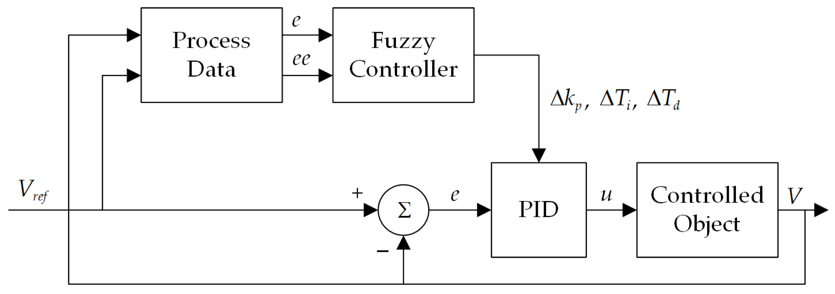
3. Design of the Fuzzy Controller

As shown in Figure 3, the structure of the digital control fuzzy control system is similar to that of the conventional digital control system [24,25,26,27,28]. The system mainly includes five parts: digital-to-analog conversion, a fuzzy controller, analog-to-digital conversion, an actuator, and a sensor. In the system’s workflow, the goal is to first obtain the analog quantity of the charged object from the input interface, convert the analog quantity into a digital quantity through analog A/D, and then send it to the fuzzy controller. The fuzzy controller outputs the digital signal after processing; after digital analog D/A conversion, it is sent to the actuator for the charged object, such as the motor voltage and current. The output signal after the controlled object passes through the sensor to output the electrical signal is needed for convenient processing by the system. The system’s performance is closely related to the accuracy and stability of the sensor; it plays an irreplaceable role in the system. Now, we explain the most important part of the whole system: the fuzzy controller. This algorithm chooses to construct different types of controllers, such as robust and sliding mode controllers, according to the specific application, the static response, the control rules, and other factors.
Figure 4 is the structure diagram of the general fuzzy control system, which is mainly composed of four parts: a knowledge base (rule base and database), a fuzzy unit, defuzzification, and a single inference engine. The fuzzy controller is the most important part of the fuzzy control system, and the structure of the fuzzy controller and the approximate inference algorithm are suitable for the design of a fuzzy controller. Among them, the most important aspect is the fuzzy rule, established based on the experience of experts or manual statistics, and it is also the most basic condition in the fuzzy control system.

3.1. Structure of the Fuzzy Controller

Figure 5 shows the fuzzy controller structure, and its working processes are as follows. First, we input the digital signal, which is processed via A/D conversion and is transferred to a fuzzy quality after fuzzification in the fuzzy inference engine. The fuzzy inference engine includes fuzzy rules and databases; after the inference processing, it outputs the conclusion. The fuzzy conclusion is directly output after the signal is processed by the expert experience. At the same time, the conclusions are also fuzzy sets, and they will be input to the next level of processing as clear values after defuzzification.
Usually, the input variable is regarded as a vector, and the dimension of the fuzzy controller refers to the number of vector components. Thus, the larger the dimension, the higher the control accuracy, but the subsequent control rules, operation amount, and inference time increase sharply, so this paper uses the two-dimensional fuzzy controller to compensate for the nonlinear change brought about by the temperature changes.
The output u of the two-dimensional fuzzy controller is the size of the forgetting factor, which is directly controlled by the output control of the fuzzy controller. The domain of the fuzzy controller input signal e (subset of error e) is e = {negative large, negative small, zero, positive small, increased} = {NB, NS, ZO, PS, PB}. The universe of the fuzzy controller output signal is u = {positive small, median, positive large} = {PS, PM, PB}. The relationship between input error e and output u is negative. The forgetting factor u’s value ranges from 0.8 to 1. The maximum affiliation method is used for defuzzification, i.e.,
ν 0 = m a x μ ν ( ν ) , ν V
where v is the variable value input to the fuzzy controller, which has a domain V. Then, the fuzzy variable value’s tolerance e and tolerance change ec are determined. After the fuzzy controller output u’ fuzzy sets and domains are determined, the subordination degree function and fuzzy language variable values need to be confirmed. Based on the ec, u fuzzy sets, and domains, the fuzzy rules can be built with the fuzzy table as u1, u2, u3…, so the control value fuzzy set Uy is represented as u = u1+ u2+ u3…+ uy.
The input and output membership function selects the triangle membership function
f ( x , a , b , c ) = { 0 x a x a b a a x b c x c b b x c 0 c x
The fuzzy forgetting factor least-squares algorithm takes into account the influence of the forgetting factor on the stability of the results and the convergence speed. In addition, the algorithm changes the size of the forgetting factor through the error between the current estimate and the real value, thus improving the stability and convergence speed of the identification results.

3.2. Establishment of Fuzzy Control Rules

The fuzzy rule table is converted from the voice control rule table, usually summarizing the operation experience in the form of “if…then…”, namely the linguistic fuzzy rule. Taking dual-input–single-output system as an example, the input quantities are set as the error e and the error variation ec, and the output quantity is u. The first step is to determine the fuzzy domain of the input variable, which can be based on the actual measurement of the data or theoretical derivation; the second step is to determine the fuzzy subset covering the fuzzy theory domain and its membership function; the third step is to form a fuzzy rule, where the method is to find the membership of the corresponding subset based on each set of data. Finally, each rule is given a strength according to the situation. If there is a contradiction in the rules, they will be discarded based on the principle of “leaving the big ones behind the small ones” [29,30,31,32]. In this way, the fuzzy rule table is formed. Due to space limitations, this paper summarizes the rules in Table 1.

3.3. Algorithm Design of the Fuzzy PID Controller

The principle of the fuzzy PID controller algorithm is shown in Figure 6: the given value and feedback value of the deviation inputs, namely the Proportion (P), Integral (I), and Differential (D), are added to compose the control value, in order to achieve the purpose of controlling the controlled object. The specific algorithm design is shown in the flow chart in Figure 5, which includes the Proportion (P), Integral (I), and Differential (D) processes. Each process is explained as follows.
Proportion Process (P): The deviation signal e(t) changes proportionally, and the control effect is the most obvious; it reflects the system in the “current” status. When the system runs, once a deviation occurs, the proportion regulation immediately acts to reduce the deviation. Thus, the larger the proportional coefficient kp, the faster the system’s response speed, but the greater the overregulation. Conversely, the response is slow and does not meet the regulation requirements.
Integral Process (I): This has the effect of reducing and eliminating static errors, which adjusts the signal of the past. The larger the system, the faster the static error of the system, and the smaller the system, the slower the static error of the system. However, if it is too large, the system response will experience oversaturation in the early stage, which can cause the system response to be over-regulated. If it is too small, it is difficult to eliminate the static error, and the adjustment accuracy is affected.
Differential Process (D): This has the role of improving the dynamic characteristics of the system, which includes the debugging of future signals. It aims mainly to suppress the change in deviation to any direction and predict the change in deviation in advance. If it is too large, the response will be known in advance and the adjustment time will be extended, thus reducing the anti-interference ability of the system.
The normal PID control is linear, and the deviation e ( t ) is obtained from the given value y d ( t ) and the actual output value y ( t ) :
e ( t ) = y d ( t ) y ( t )
The control law is written as a representation of the transfer function as
G ( s ) = k p + k i s + k d s
Among them, k p is the proportion coefficient, k i is the integral coefficient, and k d is the differential coefficient.
In the actual operation, the PMSM’s load torques and winding temperatures change constantly, and the motor’s online characteristic parameters also change. Thus, the PMSM’s working system is nonlinear. The normal PID control cannot meet the requirements of the precision control of the system. Fuzzy self-adaptive PID control is a type of intelligent control method according to the theory and method of fuzzy mathematics. The experiences and operations in the fuzzy set, and the related information, are input into the computation, and the computation will finally realize the parameter adjustments according to the actual operation conditions, fuzzy referencing, and online PID parameter set [33,34,35,36,37,38]. The input amount of the fuzzy controller in this paper is determined by deviation e and deviation e change ec, so k p , k i , k d are adjusted in real time according to the actual operation situation. Figure 7 is the block diagram of the fuzzy PID system.
In this paper, the deviation and deviation change of the motor speed are taken as the input of the fuzzy controller to correct the system in real time. The correction formula is as follows:
k p = k p 0 + Δ k p
T i = T i 0 + Δ T i
k i = k P T i
T d = T d 0 + Δ T d
k d = k P T d
where k p 0 , T i 0 , T d 0 are the initial values of the operating parameters of the motor control system.
The fuzzy algorithm’s motor controller overcomes the influence on the motor’s online parameters, which is caused by the motor’s working temperature changes; it improves the efficiency and accuracy of the motor’s magnetic chain online parameter estimation, reduces the interference of the motor parameter change on the motor control, enhances the robustness of the control algorithm, realizes the more efficient operation of the motor control system, and achieves an energy-saving effect.

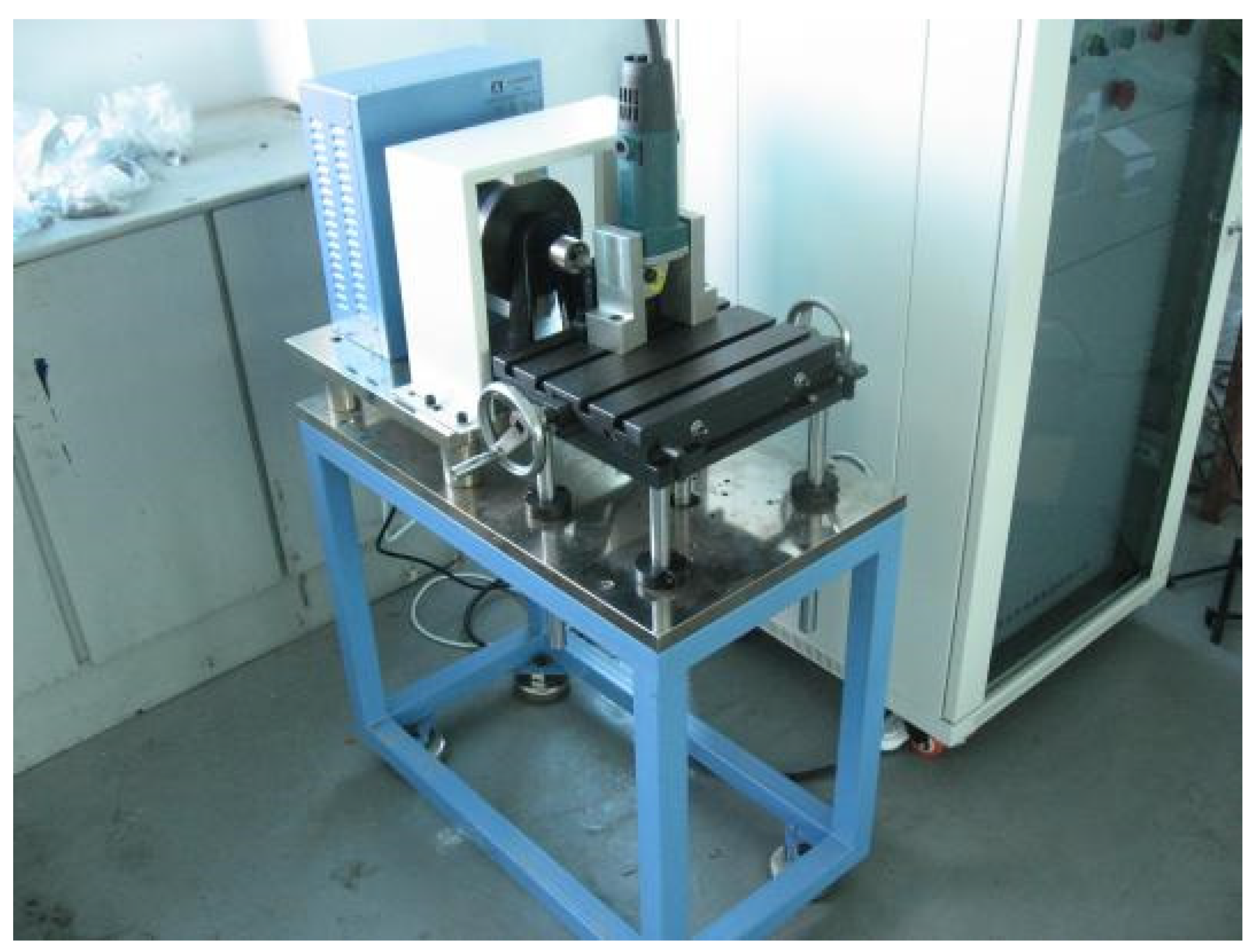
4. Design of the Experimental Set-Up

4.1. PMSM Experimental Sample Preparation

For the purpose of verifying the energy-saving effect of the fuzzy control adaptive algorithm modified in this study, a PMSM motor was constructed, and the specifications are listed in Table 2.

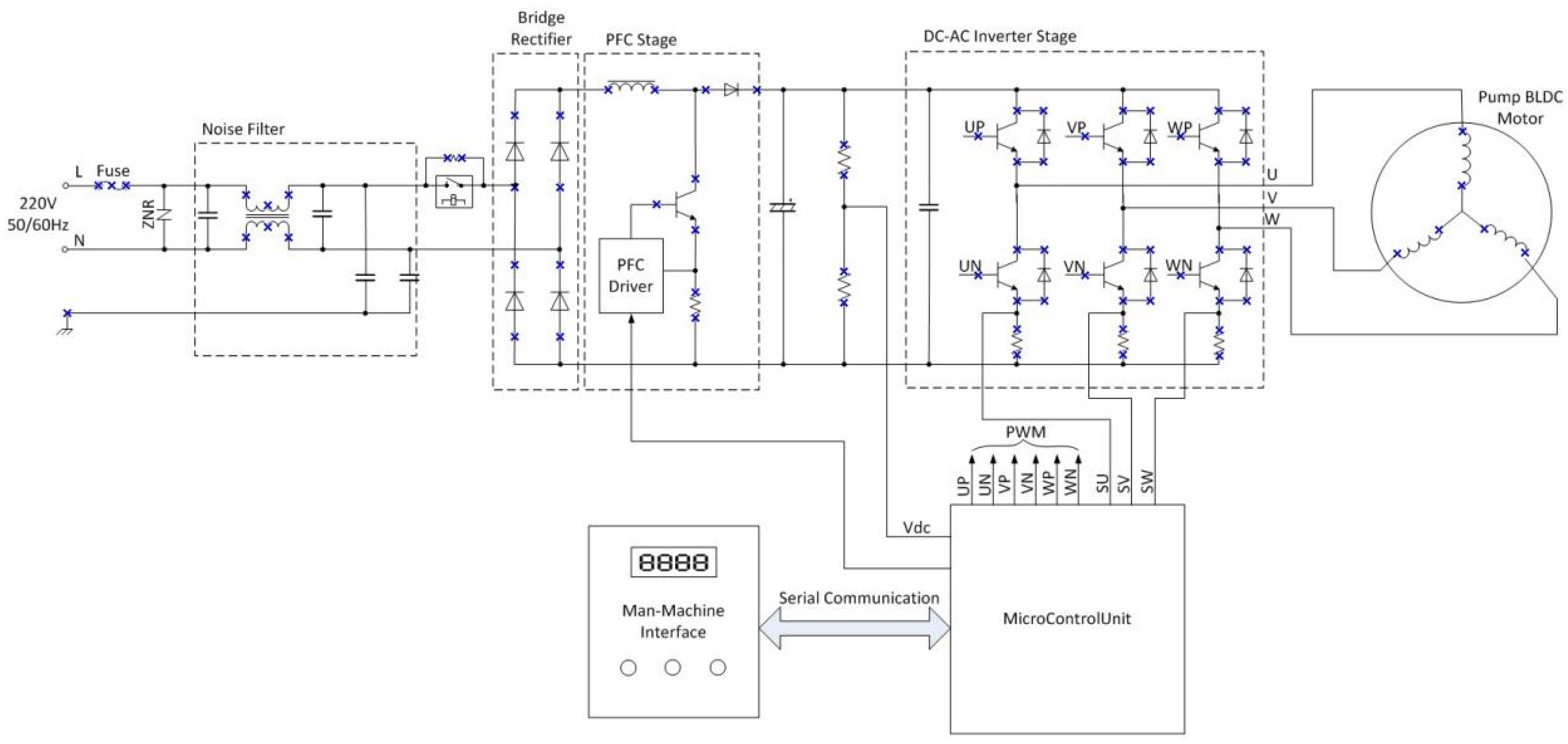
4.2. Production of the Motor Drive Circuit Board and Control Circuit Board with the Fuzzy Adaptive Algorithm

In this experiment, the control motor drive’s PCB and the operation control circuit’s PCB were constructed. The driver hardware system includes the front-stage power input and noise filtering circuit; the intermediate stage includes the single-phase full-wave rectification and power factor correction (PFC) circuit, and the rear stage is the core DC-AC inverter circuit. The noise filtering is mainly composed of a nanocrystalline inductor, which is used to eliminate the conduction emission and radiation emission noise caused by the switching action in the drive operation and meet the requirements of IEC61000-3-2 for electromagnetic compatibility. The full-wave rectification adopts a 25 A/1000 V glass passivation chip. The PFC adopts an independent PFC control chip ICE2PCS03 from the Infineon Company, which has protection functions, a wide input voltage, fast starts, and an over-voltage, over-current, and-over temperature. Moreover, the maximum power factor is close to 1. The DC-AC inverter circuit mainly uses the Intelligent Power Module (IPM) FNB41560, 15 A/600 V, which is used to convert the DC into an AC output with a variable voltage frequency and send it to the DC brushless motor, so as to control the speed and power of the motor. The core of the drive is a set of high-performance sine wave vector control algorithms (FOC). The TMS320F28027 is a motor-controlled 32-bit digital microprocessor developed by the Texas Instrument Corporation, with an instruction period of 16.67 ns (60 MHz). The efficient code of the Harvard Bus Architecture is adopted with both the C/C++ and assembly language. The configuration includes 32 k on Flash, with an 8-way enhanced complementary output PWM control peripheral, a 13-way 12-bit ADC port, and up to 22 universal GPIO control ports. There is also an integrated timer, serial communication, and comparators.
The PMSM driver and control PCB design schematic diagram is shown in Figure 8.

4.3. Comparison of the Test with the Inverter Used in the Experiment

The comparison and testing is implemented with one standard universal frequency inverter controller for PMSMs from the Delta Control company. The model number is MS300, the specification is rated as input voltage AC200–240 V (−15%~+10%), 50/60 Hz, with an output rated current of 5 A and a carrier frequency of 2–15 kHz. Delta is a well-known inverter manufacturing brand with a full range of AC and DC motor frequency conversion controller products. The device’s working principle is to transfer the input power of 220 V 50 HZ to 310 VDC with a frequency of 2–15 kHz input to each phase of the PMSM; the motor speed is determined by the frequency input into the motor winding phase. With an inverter controller, the PMSM can constantly output a certain power at a certain speed. With one motor controller, which is built with a fuzzy algorithm, this controller can perform online analysis on the motor’s magnet chain parameters and control the motor’s magnet strength in the conversion direction, which allows the input power to be precisely input to the point to precisely output a certain power at a certain speed.

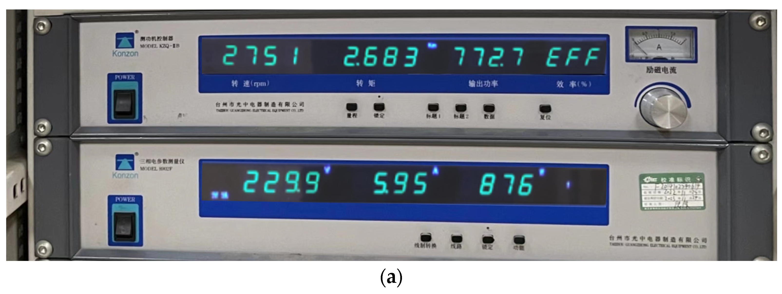
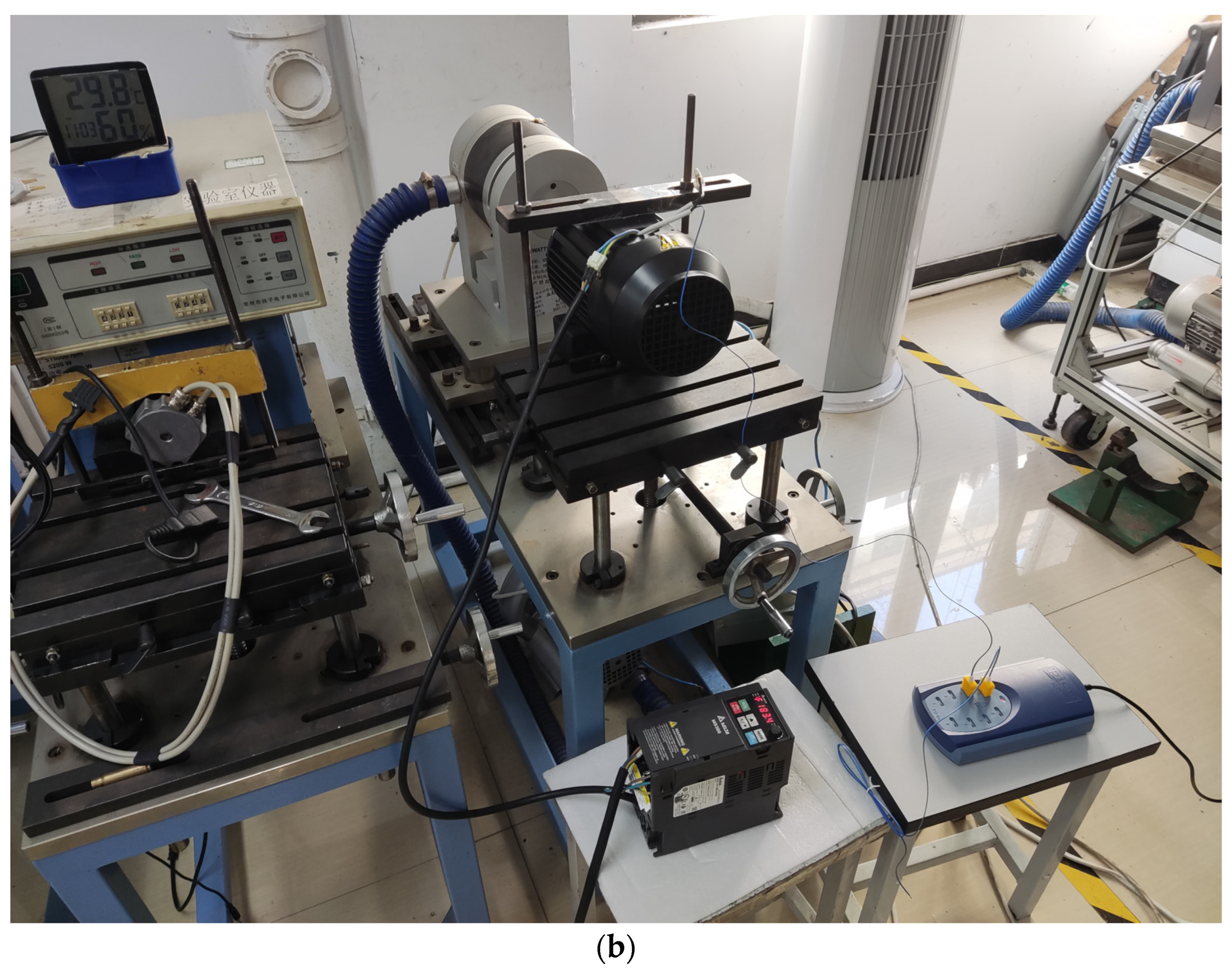
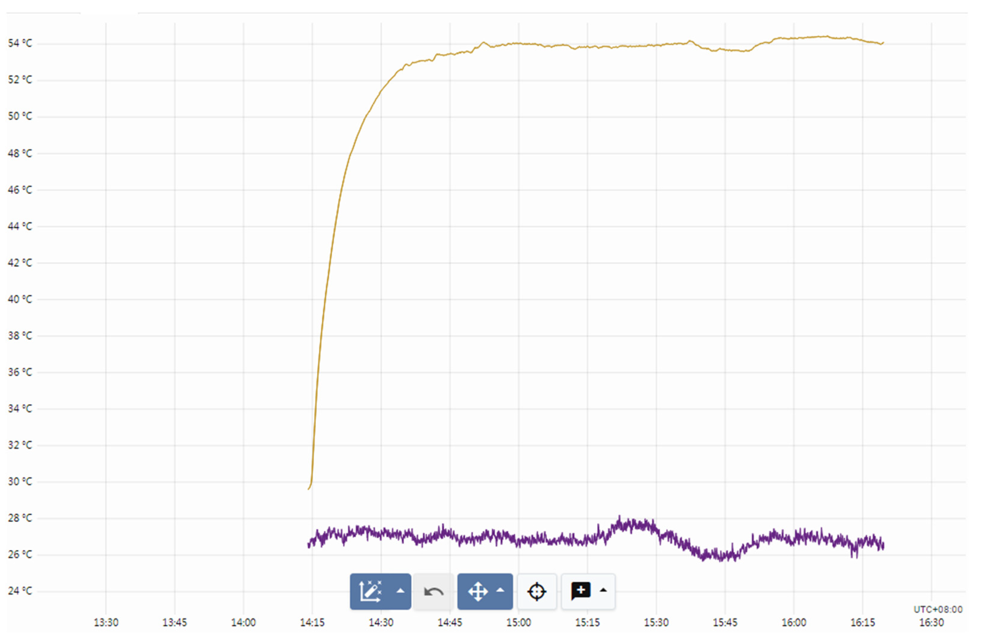
4.4. Testing of the Equipment

In Figure 9, the dynameter testing equipment is presented. Its input voltage is 230 V, 50 Hz. It has the ability to sustain a 5 N·m load test, with 50 groups of data per second at its fastest stable function when performing on-load testing.
The dynameter’s working principle means that it can output variable damping on the motor shaft to allow the motor to run at a certain speed when they are connected, so, based on the motor power function,
P = T × ω
where T is the motor output torque with the same value as the damping force, and w is the angle speed or motor RPM. Thus, this device can easily measure the motor’s output power, torque, and speed.

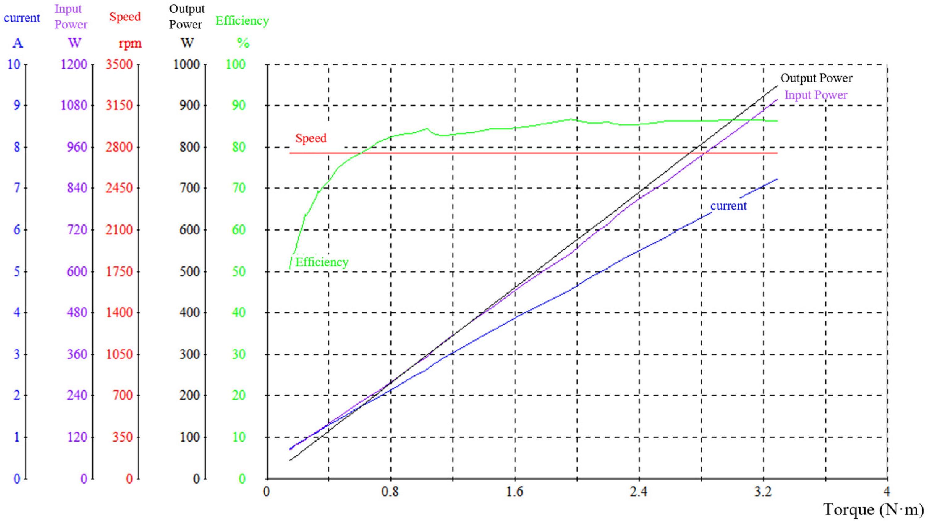
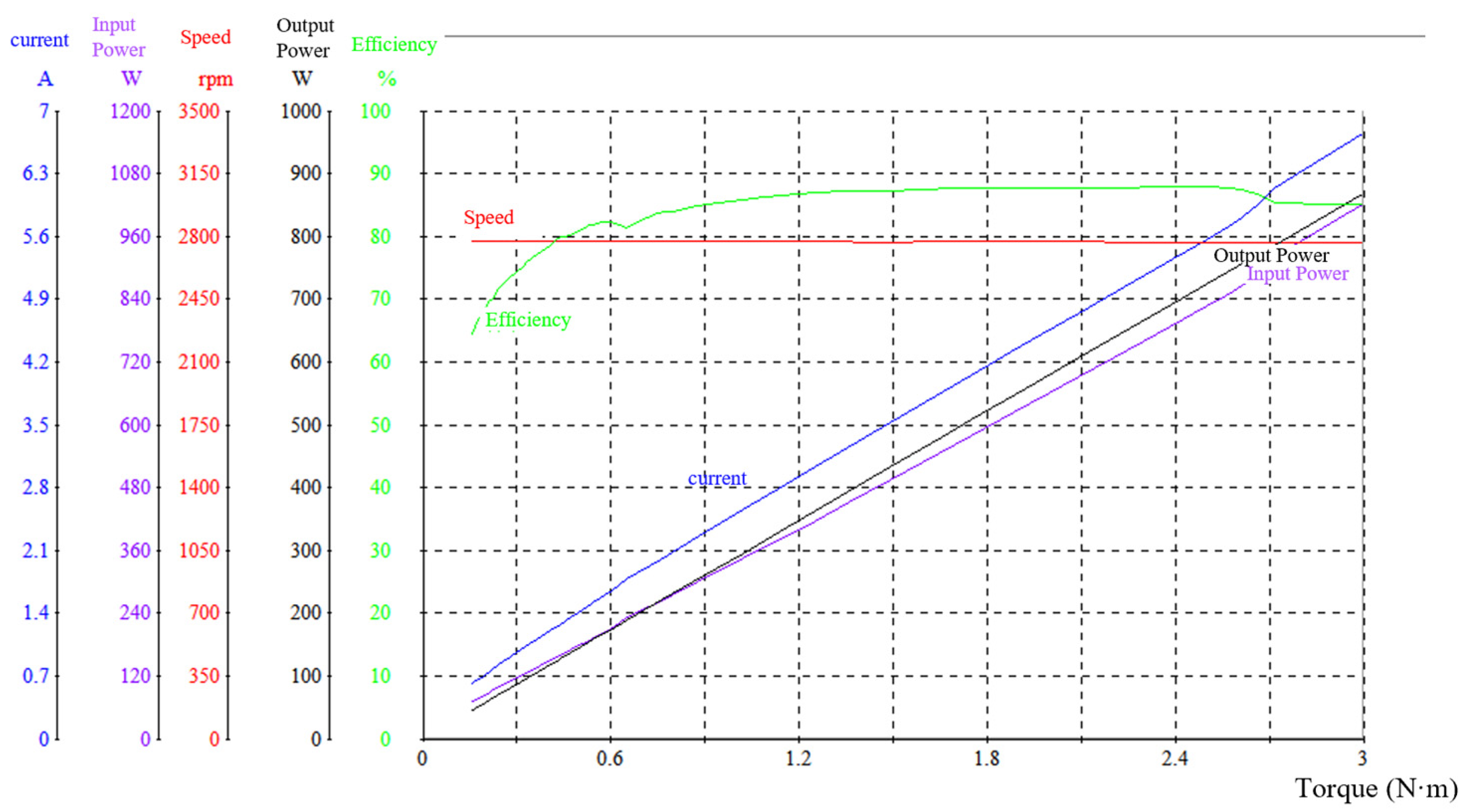
4.5. Comparison of the Experimental Results

Figure 10 below shows the parameters of the PMSM motor with inverter control during the testing of the dynamometer: the motor speed (转速) is 2751 rpm, the current (励磁电流) is 5.95 A, the input power (输入功率) is 876 W, the output power (输出功率) is 772.7 W, and the output torque (转矩) is 2.683 N·m.
Figure 11 below shows the parameters of the PMSM motor with the fuzzy control algorithm on the dynamometer: the motor speed (转速) is 2758 rpm, the current (励磁电流) is 5.8 A, the input power (输入功率) is 865 W, the output power (输出功率) is 738.9 W, and the output torque (转矩) is 2.558 N·m.
The comparison and testing considers the same PMSM motor controlled by a standard universal inverter and the self-built fuzzy algorithm controller, each for 5 min and 2 h. Moreover, we measure the motor’s three-phase resistance of U, V, W both in 5 min and 2 h, and the resistance measurement is implemented every 5 min.
Figure 12 below is a complete curve diagram of the change in U, V, W, i.e., the three-phase resistance value, and the temperature rise of the motor winding when the permanent-magnet motor + frequency converter is subjected to the 750 W load test. The purple curve is the ambient temperature, and the yellow curve is the winding temperature. When the ambient temperature is 26 °C, the final winding temperature is stable at 53 °C.
Figure 13 is a complete curve of the change in U, V, W, i.e., the three-phase resistance value, and the change in the motor temperature rise of the permanent-magnet motor + fuzzy adaptive controller during the 750 W load test. The purple curve is the ambient temperature, and the yellow curve is the winding temperature. When the ambient temperature is 26 °C, the final winding temperature is stable at 54 °C.
From Figure 12 and Figure 13 and Table 3, it can be found that the motor is operating under a constant load of 2750 rpm and 750 W output. With the extension of the operation time (from 5 min to 2 h), the temperature of the coil current and the output torque of the motor will be subjected to changes in the line of the magnetic chain of the motor. Figure 11 below shows the permanent-magnet motor measured after 5 min; the output power is 750 W, with 2.60 N·m torque, and the output speed is 2752 rpm. The motor efficiency value is 89.2%.
Figure 13 also shows the tendency of the resistance and winding temperature to be stable after a period of running, which proves that the control system will remain stable too, so the stability of the system is satisfactory [39,40].
Figure 14 shows that the value of the motor efficiency is 86.2% at the input of 229.7 V, 5.895 A and the output of 750 W, 2.60 N·m, 2751 rpm.
The comparison of Figure 14 and Figure 15 shows that the temperature and resistance value of the coil of the motor are different for the same motor for 5 min and 2 h, and a change in the resistance value will cause a change in the coil current, while a change in the coil current will cause a change in the magnetic chain. If this change is not corrected, then the efficiency of the motor will be reduced at 750 W and 2750 rpm under the same load output conditions, from 89.3% to 86.2%. The following figure shows the load test conducted on the permanent-magnet motor controlled by the fuzzy adaptive controller. The parameter values are measured when the motor runs for 5 min. At the input of 229.8 V, 5.967 A and output of 750 W and 2749 rpm, the operation efficiency of the motor is 83.9%.
As can be found in Figure 16 and Figure 17, after the temperature of the motor coil rises after 2 h of running, under the same load of 750 W and the speed of 2750 rpm, the controller with fuzzy adaptive control adjusts the magnetic chain parameters of the motor in a timely manner and continuously achieves convergence and optimization, increasing the efficiency of the motor from 83.9% to 87.7%. Figure 14 shows the parameter values measured for the permanent-magnet motor with the fuzzy adaptive controller after 2 h of load test operation: input—230.4 V, 5.749 A, output—750 W, 2767 rpm, efficiency—87.7%. It also proves that the fuzzy adaptive algorithm in the motor controller can monitor the motor’s operation time and perceive any changes in the motor’s magnetic chain. At the same time, according to the change in the magnetic chain, it can timely adjust the control parameters, enable the motor control parameters to achieve better convergence, enable the more accurate matching of the motor and controller, increase the system’s output efficiency, and improve its energy efficiency.

5. Conclusions

From the testing results of the fuzzy algorithm controller and the inverter-controlled PMSM motor, as shown in Figure 16 and Figure 17, we can find that the fuzzy-controller-controlled motor’s output efficiency is increased from 83.9% to 87.7%. This means that the fuzzy algorithm controller has better self-adaptation on the online magnet parameter searching and adjustment procedure. It performs well in terms of motor control with the same output, and it even increases the motor’s output efficiency after 2 h of running when the winding resistance changes. Meanwhile, the inverter-controlled motor’s efficiency drops from 89.2% to 86.2% because the inverter cannot adjust the control itself when the motor winding resistance changes after 2 h of running. This experiment proves that the motor’s running efficiency can be improved with better online magnet chain parameter control. Moreover, the fuzzy self-adaption algorithm could be applied in the magnet chain’s online control to improve the whole system’s output efficiency, thus reducing the energy consumption and achieving sustainable performance optimization. Although the fuzzy algorithm controller could increase the motor’s working efficiency via on-time magnet chain parameter adjustment, but it is limited by the motor design, and it could be treated as a combination of the online loss model and input-power-searching model. The fuzzy controller will work at all times to reduce the loss or input power via accurate magnet chain parameter adjustment, improving the model’s convergence and self-adjustment function.
One limitation of this experiment is that the fuzzy-algorithm-controlled motor’s starting magnet chain value set does not contain the most optimized values, which means that its starting efficiency is 83.9%; this is lower than the inverter-controlled motor’s starting efficiency, which is 89.2%. This means that the original magnet chain value set in the fuzzy algorithm does not include the most optimized values and it could be improved. However, attributed to the algorithm’s on-time convergence, the controller increases the motor’s efficiency during the motor’s magnet chain parameter adjustment. On the other hand, the inverter cannot react to the motor’s magnet chain parameter adjustment; it continues to use the original values to control the motor when the motor’s magnet chain parameters change, causing the motor’s working efficiency to decline. We believe that if the fuzzy algorithm’s starting value set is optimized, more research could be implemented, and the fuzzy self-adaptive algorithm could control the motor’s working efficiency at its highest point at each working status.
The goal of this research was to devise a new strategy to reduce CO2 emissions besides building green power factories. When people discuss sustainability, they largely focus on the building of solar panel power factories, wind turbines, and nuclear power factories, but the building of such factories produces CO2. Thus, the best means of reducing CO2 is to reduce the electricity needed. According to statistical data in China, in the year of 2022, China consumed 8.6372 trillion KWH electricity; all types of motors consumed about 60% of the total electricity, which is 5.18 trillion KWH. Although a 1% motor efficiency increase appears very small, if it is applied worldwide, such an improvement would lead to a saving of 51.8 billion KWH electricity in China, or a saving of 155.4 billion KWH electricity around the world. In our experiment, the permanent-magnet motor’s working efficiency was increased by 3% compared to its value at the beginning, and its efficiency was 1.5% higher compared to the inverter-controlled motor. It will be possible to achieve higher efficiency at each working status when the algorithm is optimized regarding its starting magnet chain value set. We believe that this research will be very meaningful in terms of sustainable development.

Author Contributions

Conceptualization, H.S. and J.Q.; funding acquisition, H.S; supervision, H.S; methodology, W.S. and J.Q., validation, W.S. and J.Q., writing—original draft, W.S., J.Q. and J.L.; writing—review and editing, W.S., J.Q. and J.L. All authors have read and agreed to the published version of the manuscript.

Funding

This research was supported in part by the Fundamental Research Funds for the Central Universities under Grant NS2022094; in part by the State Key Laboratory of Mechanics and Control for Aerospace Structures (Nanjing University of Aeronautics and Astronautics) under Grant No. MCAS-S-0224G03; in part by the First Batch of Industry-University-Research Cooperative Collaborative Education Projects of the Ministry of Education in 2021 under Grant 202101042005; in part by the Experimental Technology Research and Development Project of Nanjing University of Aeronautics and Astronautics Project under Grant SYJS202207Y; in part by the Research on Safety Risk Assessment Technology and Method of Human–Computer Intelligent Interaction in Civil Aircraft Cockpit under Grant U2033202; and in part by Research and Practice Innovation Program for Nanjing University of Aeronautics and Astronautics graduate students under Grant xcxjh20232003.

Institutional Review Board Statement

Not applicable.

Informed Consent Statement

Not applicable.

Data Availability Statement

No new data were created or analyzed in this study. Data sharing is not applicable to this article.

Conflicts of Interest

Author Wangsheng Sun was the chief executive officer of the company Nanjing Watt Electric Motors Corporation. The remaining authors declare that the research was conducted in the absence of any commercial or financial relationships that could be construed as a potential conflict of interest.

References

  1. Mi, C.; Slemon, G.R.; Bonert, R. Modeling of Iron Losses of Permanent-Magnet Synchronous Motors. IEEE Trans. Ind. Appl. 2003, 39, 734–742. [Google Scholar] [CrossRef]
  2. Slemon, G.R.; Liu, X. Core Losses in Permanent Magnet Motors. IEEE Trans. Magn. 1990, 26, 1653–1655. [Google Scholar] [CrossRef]
  3. Gao, S. Vector Control of PMSM Based on Compensating Iron Loss Influence. Electrotech. Appl. 2007, 88–92. [Google Scholar]
  4. Liu, L.; Liu, W.; Tian, J. Optimal-efficiency Control of Asynchronous Motor Taking Core Loss into Account. Micromotors 2001, 50–53. [Google Scholar] [CrossRef]
  5. Xu, Y.; Zhong, Y. Simulation of Minimum Loss Control for PMSM. J. Syst. Simul. 2007, 19, 5283–5286. [Google Scholar] [CrossRef]
  6. Xu, J.; Feng, J.; Xu, J. Direct Torque Control of Permanent Magnet Synchronous Machine Considering Loss Model. Power Electron. 2005, 39, 24–25+28. [Google Scholar]
  7. Song, J.; Su, Y. Study of efficiency-optimized control based on accurate modeling for PMSM. Adv. Technol. Electr. Eng. Energy 2004, 23, 22–25. [Google Scholar]
  8. Giorgos, M.; Manolis, M. Default Nudge and Street Lightning Conservation: Towards a Policy Proposal for the Current Energy Crisis. J. Knowl. Econ. 2023, 15, 1–10. [Google Scholar] [CrossRef]
  9. Abdulrasheed, Z.; Fatai, A.; Festus, B. The effect of energy consumption on the environment in the OECD countries: Economic policy uncertainty perspectives. Environ. Sci. Pollut. Res. 2021, 28, 52295–52305. [Google Scholar]
  10. Ma, X.; Liu, J.; Li, H.; Zhang, H. Research on Efficiency Optimization Control of Induction Motor Based on Genetic Algorithm. Micromotors 2013, 46, 36–40. [Google Scholar] [CrossRef]
  11. Sun, X.; Shi, Z.; Lei, G.; Guo, Y.; Zhu, J. Multi-Objective Design Optimization of an IPMSM Based on Multilevel Strategy. IEEE Trans. Ind. Electron. 2021, 68, 139–148. [Google Scholar] [CrossRef]
  12. Zhang, K. Study on Energy Efficiency Optimization for Electric Vehicles. Ph.D. Thesis, Tsinghua University, Beijing, China, 2014. [Google Scholar]
  13. Gautam, A.K.; Tariq, M.; Pandey, J.P.; Verma, K.S. Optimal Power Management Strategy by Using Fuzzy Logic Controller for BLDC Motor-Driven E-Rickshaw. J. Intell. Fuzzy Syst. 2022, 42, 1089–1098. [Google Scholar] [CrossRef]
  14. Zhang, L. Research on Efficiency Optimization Control of Asynchronous Motor Systems for Electric Vehicles. Ph.D. Thesis, Institute of Electrical Engineering, Chinese Academy of Sciences, Beijing, China, 2006. [Google Scholar]
  15. Sheng, Y. Efficiency Optimization Control Methods of Interior Permanent Magnet Synchronous Motors Drive System for Urban Rail Traction. Ph.D. Thesis, Central South University, Changsha, China, 2012. [Google Scholar]
  16. Liu, K.; Zhang, Q.; Chen, J.; Zhu, Z.Q.; Zhang, J. Online Multiparameter Estimation of Nonsalient-Pole PM Synchronous Machines with Temperature Variation Tracking. IEEE Trans. Ind. Electron. 2011, 58, 1776–1788. [Google Scholar] [CrossRef]
  17. Kong, X.; Liu, X. Efficient Nonlinear Model Predictive Control for Permanent Magnet Synchronous Motor. Acta Autom. Sin. 2014, 40, 1958–1966. [Google Scholar]
  18. Yang, L.; Peng, X.; Li, Z. Induction Motor Electrical Parameters Identification Using RLS Estimation. In Proceedings of the 2010 International Conference on Mechanic Automation and Control Engineering, Wuhan, China, 26–28 June 2010; pp. 3294–3297. [Google Scholar]
  19. Nahid-Mobarakeh, B.; Meibody-Tabar, F.; Sargos, F.-M. Mechanical Sensorless Control of PMSM with Online Estimation of Stator Resistance. IEEE Trans. Ind. Appl. 2004, 40, 457–471. [Google Scholar] [CrossRef]
  20. Xiao, X.; Xu, Q.; Wang, Y.; Shi, Y. Parameter Identification of Interior Permanent Magnet Synchronous Motors Based on Genetic Algorithm. Trans. China Electrotech. Soc. 2014, 29, 21–26. [Google Scholar] [CrossRef]
  21. Li, Q.; Wang, Y.; Zhang, X. Analysis and Simulation of a Variable Forgetting Factor RLS Algorithm. Mod. Electron. Tech. 2008, 17, 45–47. [Google Scholar] [CrossRef]
  22. Huang, Z.; Duan, X.; Zou, J.; Wan, H. Fault Current Parameter Estimation Based on Adaptive RLS Algorithm. Proc. CSEE 2014, 34, 2460–2469. [Google Scholar] [CrossRef]
  23. Zhang, H.; Gong, S.; Dong, Z. On-Line Parameter Identification of Induction Motor Based on RLS Algorithm. In Proceedings of the 2013 International Conference on Electrical Machines and Systems (ICEMS), Busan, Republic of Korea, 26–29 October 2013; pp. 2132–2137. [Google Scholar]
  24. Caponio, A.; Cascella, G.L.; Neri, F.; Salvatore, N.; Sumner, M. A Fast Adaptive Memetic Algorithm for Online and Offline Control Design of PMSM Drives. IEEE Trans. Syst. Man. Cybern. Syst. 2007, 37, 28–41. [Google Scholar] [CrossRef]
  25. Underwood, S.J.; Husain, I. Online Parameter Estimation and Adaptive Control of Permanent-Magnet Synchronous Machines. IEEE Trans. Ind. Electron. 2010, 57, 2435–2443. [Google Scholar] [CrossRef]
  26. Hamida, M.A.; De Leon, J.; Glumineau, A.; Boisliveau, R. An Adaptive Interconnected Observer for Sensorless Control of PM Synchronous Motors with Online Parameter Identification. IEEE Trans. Ind. Electron. 2013, 60, 739–748. [Google Scholar] [CrossRef]
  27. Noel Hernandez Perez, J.; Sandre Hernandez, O.; Morales Caporal, R.; Rangel Magdaleno, J.d.J.; Peregrina Barreto, H. Parameter Identification of a Permanent Magnet Synchronous Machine Based on Current Decay Test and Particle Swarm Optimization. IEEE Latin Am. Trans. 2013, 11, 1176–1181. [Google Scholar] [CrossRef]
  28. Wang, G.; Qu, L.; Zhan, H.; Xu, J.; Ding, L.; Zhang, G.; Xu, D. Self-Commissioning of Permanent Magnet Synchronous Machine Drives at Standstill Considering Inverter Nonlinearities. IEEE Trans. Power Electron. 2014, 29, 6615–6627. [Google Scholar] [CrossRef]
  29. Ying, H. Deriving Analytical Input–Output Relationship for Fuzzy Controllers Using Arbitrary Input Fuzzy Sets and Zadeh Fuzzy AND Operator. IEEE Trans. Fuzzy Syst. 2006, 14, 654–662. [Google Scholar] [CrossRef]
  30. Hashemzadeh, M.; Golzari Oskouei, A.; Farajzadeh, N. New Fuzzy C-Means Clustering Method Based on Feature-Weight and Cluster-Weight Learning. Appl. Soft. Comput. 2019, 78, 324–345. [Google Scholar] [CrossRef]
  31. Zhang, R.; Song, L.; Yang, J.; Hoffman, T. DC Motor Speed Control System Simulation Based on Fuzzy Self-Tuning PID. In Proceedings of the Fuzzy Information and Engineering Volume 2; Cao, B., Li, T.-F., Zhang, C.-Y., Eds.; Springer: Berlin/Heidelberg, Germany; Chongqing, China, 2009; Volume 62, pp. 967–975. [Google Scholar]
  32. Chung, I.-F.; Chen, Y.-C.; Pal, N.R. Feature Selection with Controlled Redundancy in a Fuzzy Rule Based Framework. IEEE Trans. Fuzzy Syst. 2018, 26, 734–748. [Google Scholar] [CrossRef]
  33. Stetco, A.; Zeng, X.-J.; Keane, J. Fuzzy C-Means++: Fuzzy C-Means with Effective Seeding Initialization. Expert. Syst. Appl. 2015, 42, 7541–7548. [Google Scholar] [CrossRef]
  34. Han, M.; Zhong, K.; Qiu, T.; Han, B. Interval Type-2 Fuzzy Neural Networks for Chaotic Time Series Prediction: A Concise Overview. IEEE T. Cybern. 2019, 49, 2720–2731. [Google Scholar] [CrossRef]
  35. Xie, B.-K.; Lee, S.-J. An Extended Type-Reduction Method for General Type-2 Fuzzy Sets. IEEE Trans. Fuzzy Syst. 2017, 25, 715–724. [Google Scholar] [CrossRef]
  36. Juang, C.-F.; Hung, C.-W.; Hsu, C.-H. Rule-Based Cooperative Continuous Ant Colony Optimization to Improve the Accuracy of Fuzzy System Design. IEEE Trans. Fuzzy Syst. 2014, 22, 723–735. [Google Scholar] [CrossRef]
  37. Terziyska, M.; Todorov, Y.; Dobreva, M. Efficient Error Based Metrics for Fuzzy-Neural Network Performance Evaluation. In Proceedings of the Advanced Computing in Industrial Mathematics; Georgiev, K., Todorov, M., Georgiev, I., Eds.; Springer International Publishing: Sofia, Bulgaria, 2018; pp. 185–201. [Google Scholar]
  38. Na, R.; Wang, X. An Improved Vector-Control System of PMSM Based on Fuzzy Logic Controller. In Proceedings of the 2014 International Symposium on Computer, Consumer and Control, Taichung, Taiwan, 10–12 June 2014; pp. 326–331. [Google Scholar]
  39. Zhao, K. Solvability, Approximation and Stability of Periodic Boundary Value Problem for a Nonlinear Hadamard Fractional Differential Equation with 𝓅-Laplacian. Axioms 2023, 12, 733. [Google Scholar] [CrossRef]
  40. Zhao, K. Generalized UH-stability of a nonlinear fractional coupling (𝓅1, 𝓅2)-Laplacian system concerned with nonsingular Atangana–Baleanu fractional calculus. J. Inequalities Appl. 2023, 2023, 96. [Google Scholar] [CrossRef]
Figure 1. PMSM’s dq synchronous rotation coordinate system.
Sustainability 16 01253 g001
Figure 2. PMSM FOC system schematics.
Sustainability 16 01253 g002
Figure 3. Fuzzy control system structure.
Sustainability 16 01253 g003
Figure 4. Fuzzy controller structure.
Sustainability 16 01253 g004
Figure 5. Two-dimensional fuzzy controller structure.
Sustainability 16 01253 g005
Figure 6. Fuzzy controller PID algorithm design process.
Sustainability 16 01253 g006
Figure 7. Fuzzy PID schematic diagram.
Sustainability 16 01253 g007
Figure 8. PCB design schematic diagram. (‘×’ indicates that there are 2 or more wires connected here).
Sustainability 16 01253 g008
Figure 9. On-load magnetic powder dynamo testing meter.
Sustainability 16 01253 g009
Figure 10. Inverter-controlled PMSM with load testing. (a) Inverter-controlled PMSM with load testing results displayed; (b) Inverter-controlled PMSM during load testing on the dynameter.
Sustainability 16 01253 g010aSustainability 16 01253 g010b
Figure 11. Self-built fuzzy-controller-controlled motor during load testing. (a) Fuzzy-controller-controlled PMSM with load testing results displayed. (b) Fuzzy-controller-controlled PMSM with load testing on the dynameter.
Sustainability 16 01253 g011aSustainability 16 01253 g011b
Figure 12. Inverter-controlled motor winding temperature changes. (The yellow curve is the winding temperature; the purple curve is the environment temperature).
Sustainability 16 01253 g012
Figure 13. Fuzzy-controller-controlled motor winding temperature changes. (The yellow curve is the winding temperature; the purple curve is the environment temperature).
Sustainability 16 01253 g013
Figure 14. Inverter-controlled PMSM’s efficiency when its winding is cold (after running for 5 min).
Sustainability 16 01253 g014
Figure 15. Inverter-controlled PMSM’s efficiency when its winding is hot (after running for 2 h).
Sustainability 16 01253 g015
Figure 16. Fuzzy-algorithm-controlled PMSM’s efficiency when its winding is cold (after running for 5 min).
Sustainability 16 01253 g016
Figure 17. Fuzzy-controller-controlled PMSM’s efficiency when its winding is hot (after running for 2 h).
Sustainability 16 01253 g017
Table 1. Fuzzy rule table.
ECNBNMNSZOPSPMPB
U
E
NBPBPBPBPBPMPMPS
NMPBPBPBPMPMPSZO
NSPMPMPMPSPSZONS
ZOPMPMPSZONSNMNM
PSPSPSZONSNSNMNB
PMZOZONSNMNMNBNB
PBZOZONMNBNBNBNB
Table 2. Specifications of the PMSM for experiment.
VariableParameter
Number of phases3
Number of poles8
Rated voltage (VDC)300
No load speed (rpm)2850
No load current (a)0.63
Rated speed (rpm)2850
Rated torque (N·m)2.5
Rated power (W)750
Rated current (A)3.8
Max peak torque (N·m)2.9
Table 3. Motor winding’s 3-phase resistance changes.
Motor TypeU Phase (Ω)V Phase (Ω)W Phase (Ω)
PMSM + Inverter (in 5 min)2.347 Ω2.353 Ω2.351 Ω
PMSM + Inverter (in 2 h)2.496 Ω2.488 Ω2.47 Ω
PMSM + Fuzzy Controller (in 5 min)2.334 Ω2.334 Ω2.34 Ω
PMSM + Fuzzy Controller (in 2 h)2.571 Ω2.576 Ω2.552 Ω
Disclaimer/Publisher’s Note: The statements, opinions and data contained in all publications are solely those of the individual author(s) and contributor(s) and not of MDPI and/or the editor(s). MDPI and/or the editor(s) disclaim responsibility for any injury to people or property resulting from any ideas, methods, instructions or products referred to in the content.

