1. Introduction
The emergence of high-speed fifth generation (5G) networks has enabled cars to operate with reduced human intervention on the road. Autonomous vehicles (AVs) have gained popularity in recent years as intelligent modes of transportation, sparking interest among researchers and innovators worldwide. This autonomous feature not only enhances operational reliability but also offers a convenient and stress-free commuting experience, especially in challenging conditions where visibility is limited, or road conditions and traffic congestion are unpredictable [
1,
2,
3]. AVs can significantly reduce road accidents and optimize fuel consumption [
4]. One key sensing mechanism used in AVs for detecting their surroundings is the photonic radar system [
5]. Photonic radar employs light waves to detect objects, measure their distance, velocity, and other characteristics, and can be seamlessly integrated with 5G networks to provide more comprehensive and precise environmental awareness for autonomous vehicles and IoT devices [
5]. The high-speed and low-latency communication capabilities of 5G networks are leveraged to transmit the large volumes of data generated by photonic radar systems in real time. This integration unlocks a wide array of applications, including enhanced safety measures, improved navigation systems, and increased operational efficiency for autonomous vehicles. Essentially, photonic radar sensors operate on the same principles as traditional radar, but in the optical domain [
6]. However, traditional microwave radars face challenges such as large beam divergence due to their larger aperture, resulting in reduced angular resolution that makes it difficult to distinguish between multiple targets. Additionally, microwave radars operate on radio frequencies that are susceptible to electromagnetic interference and produce significant heat signatures [
7,
8]. The applications of AVs demand photonic radar systems to operate at high frequencies with wide bandwidths. Initially, AVs used industrial, scientific, and medical (ISM) or K-band frequencies (24 GHz). However, due to the limitations of lower bandwidth, the operation of AVs gradually transitioned towards short-range radar (SRR) or millimeter-wave (mm-wave) bands (77–81 GHz) [
9]. A high bandwidth not only utilizes smaller antenna dimensions but also enhances angular resolution. Moreover, the bandwidth achievable in these high-frequency bands, typically around 15 GHz [
10,
11], further improves the accuracy in detecting and identifying obstacles.
Figure 1 shows the general scenario of autonomous vehicles. Range resolution is a crucial aspect of photonic radar, as it enables the system to differentiate between closely located targets. This capability is dependent on the bandwidth of the system, as a higher bandwidth results in improved range resolution [
3]. With higher frequencies, the effect of atmospheric attenuation becomes more pronounced, which can limit operational functions such as elongated target detection and ranging. This often necessitates keeping the operational frequency at a minimum. As AVs operate in complex scenarios where multiple targets may approach, photonic radar sensors must possess the capability to detect multiple targets with precision. In the context of AVs, photonic radar sensors serve as a crucial component for detecting and tracking objects in the vehicle’s environment, including other vehicles, pedestrians, and obstacles. Photonic radar offers several advantages over traditional radar systems, including higher resolution and the ability to operate effectively in a broader range of weather conditions [
12,
13]. Moreover, photonic radar can seamlessly integrate with other sensor systems, such as cameras and light detection and ranging (LiDAR), to provide a more comprehensive and precise view of the vehicle’s surroundings. In recent years, extensive research efforts have focused on the development of photonic radar systems for autonomous vehicles, with the ultimate goal of enhancing safety and efficiency in autonomous driving. The main contributions in this work can be highlighted as follows:
- (1)
Hybrid Multiplexing Scheme: This study introduces a hybrid multiplexing scheme that combines mode-division multiplexing (MDM) and polarization-division multiplexing (PDM) in a photonic radar system.
- (2)
Effective Target Detection in Adverse Conditions: The proposed photonic radar system demonstrates its effectiveness in detecting multiple targets under challenging conditions, including scenarios with high atmospheric attenuation and low material reflectivity. This achievement is a crucial step towards improving the reliability of radar systems for autonomous vehicles operating in real-world settings.
- (3)
Enhancing Road Safety for Autonomous Vehicles: The technology presented in this study has the potential to significantly enhance road safety for autonomous vehicles. By reducing human errors and enabling accurate and efficient mapping of road conditions, the system contributes to the development of safe and reliable autonomous transportation systems.
- (4)
Robust and Reliable Solution: The results of this study highlight the robustness and reliability of the MDM-PDM based photonic radar system. It successfully detects multiple targets while considering variations in material reflectivity, making it a promising solution for practical applications.
- (5)
Addressing the State of the Art: By providing detailed insights into the system’s design, implementation, and performance evaluation, this study contributes to the state of the art in photonic radar systems. It offers a unique approach and a clear demonstration of its effectiveness, advancing the field’s understanding of radar technology for autonomous vehicles.
Figure 1.
Illustration of autonomous vehicle scenarios.
Figure 1.
Illustration of autonomous vehicle scenarios.
2. Related Works
MDM is a multiplexing technique in optical communication that leverages the different modes or spatial channels within an optical fiber to transmit multiple signals simultaneously. Each mode represents a distinct path for light to travel through the fiber. By manipulating the light’s spatial distribution, MDM enables the transmission of multiple data streams independently within a single optical fiber. It is a valuable technique for increasing the data-carrying capacity of optical communication systems. On the other hand, PDM is another multiplexing method used in optical and wireless communication systems. It exploits the polarization properties of electromagnetic waves, such as light or radio waves. PDM typically involves transmitting two or more signals with different polarizations simultaneously. By using polarizations that are orthogonal to each other, PDM allows multiple independent signals to share the same transmission medium without interference. PDM is widely used in optical fiber communication, especially in long-haul and high-capacity transmission systems. In our work, the combination of MDM and PDM in our photonic radar system allowed for the simultaneous transmission and reception of multiple signals while maintaining their independence, making it a powerful approach for target detection. In this section, we have compiled a selection of key works on photonic radar in recent years. These studies shed light on the evolving landscape of photonic radar technology and its growing importance, particularly in the realm of autonomous vehicles (AVs). In 2019 [
14], the authors suggested a silicon-based photonic radar that had the capability to achieve a resolution of 2.7 cm with an error margin of less than 2.75 mm. In another work [
15], the authors introduced a photonic radar that could support bandwidth up to 1.6 GHz. In another work [
16], the authors presented a photonic radar design that incorporated a photonic frequency doubling transmitter and a balanced phase and quadrature de-chirp receiver. This proposed radar system was able to achieve a bandwidth of 8 GHz. In 2020 [
17], the authors proposed photonic radar by employing wavelength division multiplexing (WDM) and a radio-over-fiber technique for the generation and distribution of radar signals. The proposed microwave photonic radar offers a range resolution of 7.3 cm. In another work [
18], the authors introduced a microwave photonic radar that incorporated a post-bandwidth synthesis scheme. This proposed radar system can achieve a bandwidth of 16 GHz and a range resolution of 1 cm. In 2021 [
19], the authors suggested a microwave-based photonic radar system that has the ability to detect the distance and direction of targets simultaneously. The reported results show the directional measurement of from −72.5° to 72.5°, with an error of less than 1.6°. In another work [
20], the authors proposed the use of an X-band photonic radar system, employing a photonic frequency quadrupling scheme, to achieve the real-time detection of low-radar cross-section targets as well as high-resolution imaging. To further improve the signal-to-noise ratio, a balanced photo detector and a delay interferometer were used. The proposed photonic radar system successfully detected a target located 2.7 km away from the radar. In 2022 [
21], the authors compared the performance of direct detection FMCW-based photonic radar and coherent detection FMCW-based photonic radar. The reported results show the performance of coherent detection-based photonic radar as better compared to direct detection FMCW-based photonic radar. However, the coherent FMCW-based photonic radar is more complex and costly compared to direct detection FMCW-based photonic radar. In another work [
22], the authors proposed a microwave photonic radar, which employs sparse stepped-frequency (SSF) chirp signals to achieve ultra-high resolution. The proposed photonic radar can distinguish two simulated point targets placed within the distance of 8.3 mm. In another work [
23], the authors proposed a photonic assisted millimeter wave radar, which can perform a communication function as well as a radar function. The proposed joint communication and radar system can provide a range resolution of 1.5 cm and an 8 Gbps data rate. In another work [
24], the authors suggested a compressive sensing-based microwave photonic radar that can measure both the distance and speed of targets. The proposed radar system generates LFM signals using a DPMZM, then processes the received signals using a DDMZM and MZM cascaded with a PRBS for optical mixing and de-chirp processing. The mixed signal is then converted to a digital signal by an ADC at a lower sampling rate and reconstructed using a compression algorithm with a compression ratio of 8. The experimental results showed a distance measurement error of 1.560 cm when the target was stationary, with an SNR of 30.725 dB. Simulations of the proposed radar system for a moving target demonstrated a maximum distance error of 1.2 cm and a velocity error below 0.140 m/s.
On the other hand, mode-division multiplexing (MDM), a technique initially developed to expand the capacity of optical communications, has found versatile applications in various fields, including photonic radar systems. This innovative approach enables the simultaneous transmission of multiple optical modes within a single optical fiber, thereby enhancing data transmission capabilities. MDM is a type of multiplexing technique that enables the simultaneous transmission of multiple data streams over a single optical fiber or free-space optical (FSO) network. MDM is based on the concept of using different modes, or spatial channels, to transmit data. Each mode can be thought of as a unique path that allows for light to travel through fiber or an FSO, and each mode can carry its own data stream. This allows for multiple streams of data to be transmitted simultaneously over a single fiber or FSO, increasing the capacity of the optical network. While MDM has been extensively investigated and applied in optical communication and optical wireless communication, its utilization in the realm of photonic radar systems remains relatively uncharted territory. Therefore, MDM holds significant promise as a transformative technology in the field of photonic radars, offering the potential to enhance their capabilities and broaden their applications.
In addition to mode-division multiplexing (MDM), another notable technique that significantly contributes to the advancement of photonic radar technology is polarization-division multiplexing (PDM). PDM, which exploits different polarization states of light to convey information, has demonstrated its value in optical communication systems. Interestingly, to further amplify spectral efficiency and optimize performance, PDM is frequently harnessed alongside MDM [
25].
In this work, we leveraged a hybrid multiplexing strategy, combining the advantages of both MDM and PDM, to significantly expand the target detection capabilities of our photonic radar system. By harnessing the unique characteristics of MDM and PDM, we aimed to enhance the precision and efficiency of target detection, particularly within the context of autonomous vehicles (AVs). Our proposed system operates at a center frequency of 77 GHz with a bandwidth of 8 GHz, demonstrating its capability to navigate the complexities of real-world scenarios and atmospheric conditions. The integration of MDM and PDM serves as a testament to the versatility and potential of hybrid multiplexing techniques in advancing photonic radar technology for AV applications. The remaining paper is organized as follows:
Section 3 includes a system description of the proposed MDM-PDM-based photonic radar sensor, while results and discussion are presented in
Section 4.
Section 5 concludes the paper, and future work is presented in
Section 6.
3. Proposed MDM-PDM-Based 8 GHz Bandwidth-Enabled Photonic Radar
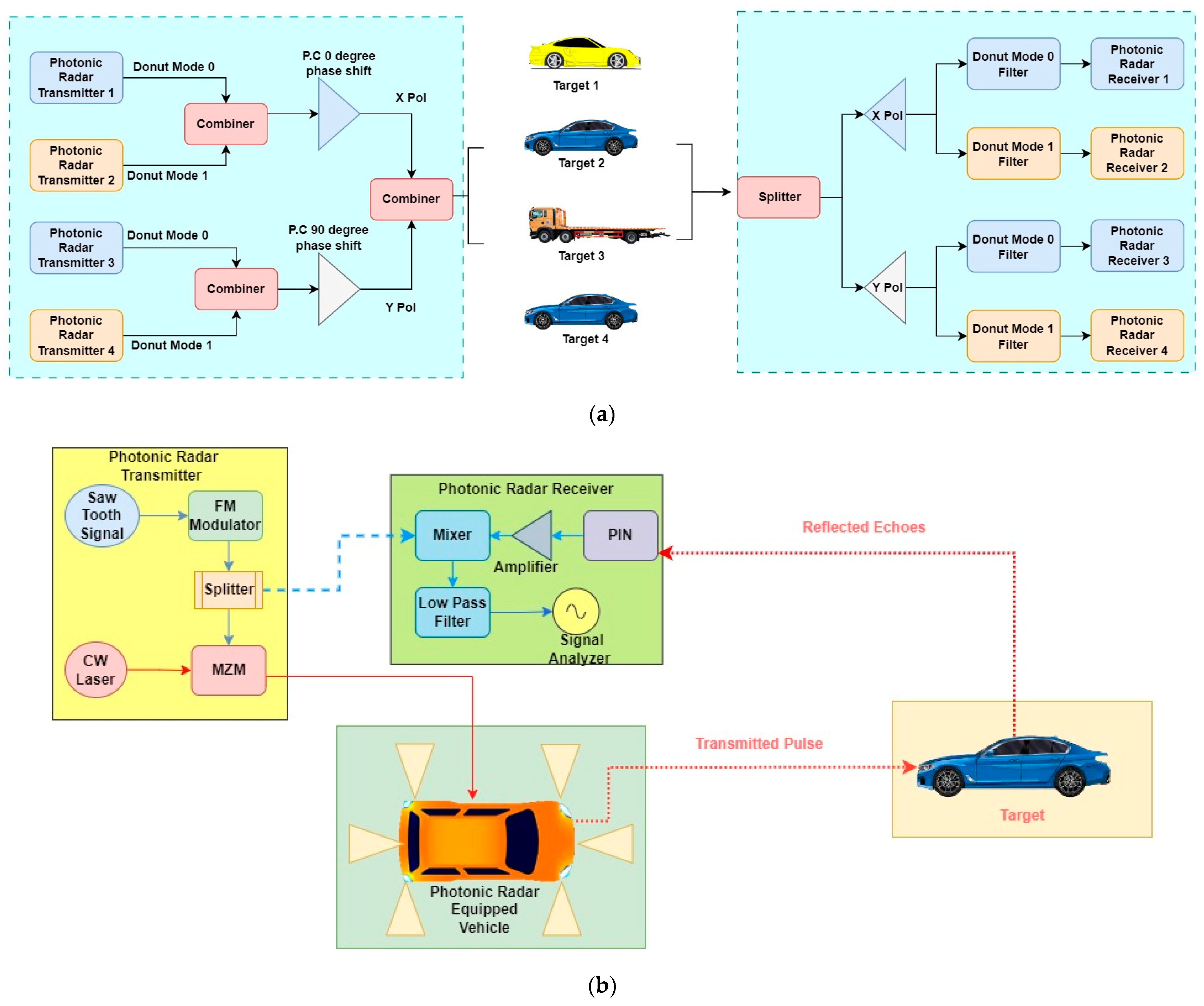
In this section, we delve into the details of our proposed photonic radar system, which leverages a hybrid approach combining MDM and PDM as shown in
Figure 2. Our system is designed to operate within an 8 GHz bandwidth and has a center frequency of 77 GHz. Our system boasts compact dimensions and minimal power input as its key advantages. The four photonic radar signals are combined using an MDM and PDM scheme and transmitted over a free-space link toward the targets.
As shown in
Figure 2a, in our system, the first transmitter operates on Donut mode 0, while the second transmitter operates on Donut mode 1.
Figure 3 illustrates the excited donut modes using a donut mode generator. Donut modes possess distinctive properties, including high confinement, low loss, and high nonlinearity, making them valuable for various applications, including sensing, nonlinear optics, and MDM in optical communication systems. The outputs of transmitters 1 and 2 are combined, and a 0-degree phase shift is applied to the output (X polarization) using a polarization controller. Similarly, transmitter 3 operates on Donut mode 0, and transmitter 4 operates on Donut mode 1. The outputs of transmitters 3 and 4 are combined, and a 90-degree phase shift is introduced to the output (Y polarization) using a polarization controller.
Figure 4 shows the optical spectrum of all the transmitters for both X and Y polarizations. A sharp optical spectrum is obtained using a highly precise resolution bandwidth of 0.001 nm in the optical spectrum analyzer. Each transmitter is equipped with a saw-tooth wave generator that converts a 90 Kbps pseudo-random sequence into a triangular sweep signal with an amplitude of 1 a.u. and a sample rate of 819.19 Mbps. The input triangular signal is then fed into a linear frequency modulator (LFM), which modulates the signal into a frequency-modulated continuous wave signal with a center frequency of 77 GHz and a bandwidth of 8 GHz. As elaborated in the Introduction, a higher bandwidth not only reduces antenna dimensions but also enhances precision in range resolution.
The output from the X polarization and Y polarization signal is combined and then fed into an optical telescope with a transmitter aperture of 5 cm to transmit the signal into free space, and reflected echoes from the target are collected back using a receiver aperture of 15 cm. The received signal is de-multiplexed and fed to a polarization splitter that redistributes the signal, based upon the state of the polarization, to the corresponding receiver.
The detection of a target is based upon the frequency of received echoes, also known as range frequency, which is calculated in Equation (1) [
26,
27]:
where
R denotes the range of target in meters,
B is bandwidth of the system in Hz,
Ts is the sweep time, and
C is the speed of light.
Numerous aspects, such as refractive index variations in the free-space channel, target reflectivity, and dispersion affects the received echo signal power
Pr and is given as Equation (2) [
26]:
where the aperture width of the receiver is given as
D, the distance between sensor and target is known as a range given by
R,
ρt represents the reflectivity of the target,
τopt and
τatm represent the transmission loss and atmospheric loss factors, effective area is given as
At, and
Aill represents the illuminated area of the target, respectively.
Furthermore, for the selection of specific modes, a mode selector filter is employed to isolate the corresponding mode. The received signal is detected using a PIN-type photodiode with a dark current of 10 nA and responsivity of 1 A/W
−1, along with a load resistance of 50 Ω. Various device-related constraints, such as shot noise, thermal noise, and amplified spontaneous noise (ASE), are considered in the analysis. The responsivity of the PIN photodiode used in this sensor is represented as
ℜ, and the output photocurrent is denoted as
given in Equation (3) as [
27]:
where
is the responsivity of the PIN photodiode,
is the received optical power,
is the modulation index,
is the carrier frequency,
is the time,
is the time delay,
is the signal bandwidth, and
is the modulation period.
The photodiode output is measured using an electrical signal analyzer where the maximum received power and signal-to-noise ratio (
SNR) are measured. Theoretically,
SNR is given as Equation (4):
In Equation (4), is the electronic charge, is the modulation index, is the responsivity of the PIN photodiode, is the received optical power, is the bandwidth of the receiver, is the Boltzmann constant, is the absolute temperature of the receiver, and is the load resistance.
To enhance the sensitivity of the system, an electrical amplifier with a gain of 40 dB is employed to amplify the output from the PIN detector. This amplified signal is then mixed with the signal generated by the linear frequency modulator (LFM). The mixer combines these signals, and the resulting output is directed into a low-pass filter. Within the filter, the beat signal is extracted, as described by the following:
In Equation (5), is the amplitude of the carrier signal, is the responsivity of the PIN photodiode, is the received optical power, is the modulation index, is the carrier frequency, is the time, is the time delay, and is the frequency of the reference signal or local oscillator.
The filtered signal is observed using an RF spectrum analyzer, and range frequency peaks are verified with theoretical values given in Equation (1). The range resolution
LRES is defined as Equation (6):
where the speed of light is denoted by
c, and the bandwidth of the system is represented by
B.
4. Results and Discussion
In this section, we present the results of our simulative investigation into the performance of our proposed MDM-PDM-based 8 GHz bandwidth-enabled photonic radar system.
Figure 5 shows the range frequency plots of all the targets without the use of any multiplexing scheme. It shows that, without multiplexing, the targets’ signals are prone to interference from one another (crosstalk) or attenuation, making it difficult to discern individual target echoes with high confidence. On the other hand,
Figure 6 shows the range frequency plots of all targets with the use of an efficient PDM-MDM scheme under clear weather conditions.
Notably, our system demonstrated its capacity for the detection of multiple targets, with the calculated range frequency values obtained from Equation (1) aligning closely with the reported range frequencies, as depicted in
Figure 6. For the ease of simulations, we assumed that target 1 is located at 50 m from the photonic radar-equipped vehicle, target 2 is located at 35 m, whereas targets 3 and 4 are located at 25 m and 15 m, respectively. For target 1, the calculated range frequency was 266.66 MHz; for target 2, it was 186.66 MHz; for target 3, 133.33 MHz; and for target 4, an 80 MHz range frequency was calculated. As highlighted in
Figure 6a–e, the corresponding peaks and range frequency values unequivocally demonstrate the successful detection of multiple targets using the proposed system under clear weather conditions, characterized by a relatively low attenuation factor of 0.14 dB/km.
Likewise, our proposed system was tested under the influence of substantial attenuation, reaching 75 dB/km, as depicted in
Figure 7. As expected, the impact of this heavy attenuation is evident in the observed loss of received power. However,
Figure 7 showcases that, despite the challenging conditions characterized by heavy fog and the high attenuation factor, the system continued to successfully detect multiple targets, with their corresponding range frequency values clearly identifiable. In addition to atmospheric factors, the effectiveness of photonic radar also hinges on the material reflectivity of the targets in its field of view.
Moreover, we have also assumed the scintillations to be strong by considering the gamma-gamma modeling. The value of the Cn is considered as
(strong turbulences) [
28]. To comprehensively assess our system’s performance, we considered three scenarios with varying material reflectivity coefficients: 85%, 50%, and 20%, representing the fraction of incident power reflected by the material. An 85% reflectivity coefficient means that only 85% of the transmitted signal is reflected back from the material (targets).
Figure 8 offers a visual representation of the detection of multiple targets under decreasing reflectivity coefficients. As illustrated in
Figure 8a, we successfully detected target 1 at a range frequency of 266.66 MHz, which closely aligns with the theoretical value calculated using Equation (1). The impact of varying material reflectivity is evident, demonstrating that a decreasing reflectivity coefficient results in a reduction in the maximum total received power. In
Figure 8a, the maximum power received for an 85% reflection coefficient is −6.57 dBm, while it decreases to −14.69 dBm for a 50% reflection coefficient, and, for a 20% reflection coefficient, it diminishes further to −20.07 dBm. Similarly, in
Figure 8b, target 2 was detected at a range frequency of 186.66 MHz, confirming the agreement between the observed value and the theoretical calculation from Equation (1). The impact of varying material reflectivity on received power is once again evident, with decreasing reflectivity coefficients leading to reduced maximum total received power. In
Figure 6b, the maximum power received for an 85% reflection coefficient is −19.40 dBm, while it drops to −22.05 dBm for a 50% reflection coefficient, and this figure further decreases to −35.43 dBm for a 20% reflection coefficient.
As depicted in
Figure 8c, our radar system effectively detected target 3 at a frequency of 133.33 MHz, and the range frequency closely matched the expected value calculated using Equation (1). The effect of varying material reflectivity is evident, with a noticeable decrease in the maximum total received power as the reflectivity coefficient decreases. In
Figure 8c, the maximum power received for an 85% reflection coefficient is −6.12 dBm, with a slight decrease to −14.13 dBm for a 50% reflection coefficient, while this figure further reduces to −19.72 dBm for a 20% reflection coefficient. Similarly, in
Figure 6d, we successfully detected target 4 at 80 MHz, and the range frequency matches the theoretical calculation from Equation (1). In
Figure 8d, the maximum power received for an 80% reflection coefficient is −6.21 dBm, slightly decreasing to −9.02 dBm for a 50% reflection coefficient, while this value further diminishes to −22.53 dBm for a 20% reflection coefficient. Importantly, the results display independent and non-overlapping peaks, affirming the successful detection capabilities of our proposed MDM-PDM-enabled photonic radar system. Thus, the variations in maximum received power across
Figure 8a,b are primarily attributed to the material reflectivity coefficients associated with the respective targets. Higher reflectivity coefficients result in stronger radar signals and, consequently, higher received power levels. These trends hold substantial real-world implications, as they mirror the diverse material properties and reflectivity characteristics encountered in autonomous vehicle scenarios. Furthermore,
Figure 8c,d demonstrates our radar system’s ability to reliably detect targets 3 and 4, reaffirming the robustness of our MDM-PDM-enabled photonic radar system. These findings are consistent with theoretical calculations, validating the system’s effectiveness.
Table 1 shows a comparison of the performance of our proposed photonic radar with previous works.
As shown in
Table 1, our work utilizes FMCW radar in the W band with an 8 GHz bandwidth, enabling the detection of up to four targets. The high attenuation of 75 dB/km is considered, as well as the presence of solar background noise. This represents a notable advancement in radar technology for autonomous vehicles, particularly in challenging environments. The comparison reveals that our proposed photonic radar system in the W band exhibits several advantages. It enables the detection of multiple targets, addressing a limitation in some existing radar systems where only a single target is detected. Furthermore, the consideration of high attenuation levels and solar background noise makes our system suitable for a wider range of real-world scenarios, particularly for autonomous vehicles operating in challenging environments.
In summary, our work demonstrates the potential for significant advancements in radar technology for 5G autonomous vehicles. By incorporating cutting-edge photonic radar techniques, we address key limitations in existing radar systems, paving the way for enhanced performance and safety in autonomous vehicle applications.
5. Conclusions
In conclusion, this work successfully demonstrated a photonic radar system operating on the FMCW principle. Utilizing two distinct Donut modes (Donut mode 0 and Donut mode 1) and a PDM scheme, the system exhibited the capability to detect up to four targets on the road. The modeling of the MDM-PDM-based photonic radar was conducted using OptiSystemTM (V.19) and MATLABTM (V.r2022b) software, yielding simulative results that confirmed the system’s proficiency in detecting all four targets at the receiver. Notably, the system operated with an 8 GHz bandwidth and a 77 GHz frequency modulation, showcasing its potential for high-resolution target detection. Furthermore, the impact of material reflectivity from the targets was evaluated across a range of scenarios, from 85% down to 20%. Encouragingly, the simulation results demonstrated that, even with a material reflectivity as low as 20%, the photonic radar system reliably detected all targets. This research contributes to the advancement of photonic radar technology, with potential applications in enhancing road safety and enabling autonomous vehicles (AVs). The system’s robustness and adaptability make it a promising candidate for revolutionizing transportation by reducing errors, improving navigation, and optimizing road conditions. Thus, this study underscores the transformative potential of photonic radar technology, paving the way for safer, more efficient, and technologically advanced transportation systems.
6. Future Work
As this research lays a solid foundation for photonic radar technology in the context of autonomous vehicles, there are promising avenues for future exploration. One area of focus could be the development of advanced signal processing algorithms to enhance the system’s target classification capabilities. By incorporating machine learning and artificial intelligence, the photonic radar system could not only detect but also classify different types of targets, such as pedestrians, vehicles, and obstacles. Additionally, the expansion of the system’s operational range in adverse weather conditions presents an exciting challenge. Future work may involve optimizing the system’s performance under various environmental factors, including rain, snow, and fog. This could lead to the development of all-weather photonic radar systems, further enhancing the safety and reliability of autonomous vehicles. Furthermore, the integration of real-time data fusion with other sensor technologies, such as LiDAR and cameras, can provide a comprehensive perception system for autonomous vehicles. Investigating the seamless integration of photonic radar with these sensors is a promising avenue for future research, with the potential to create a multi-sensor fusion approach for enhanced perception and decision-making in autonomous driving scenarios.
In conclusion, the future of photonic radar technology is ripe with possibilities, and this research represents a significant step toward realizing its potential. Continued research and development in these directions will undoubtedly contribute to the advancement of autonomous vehicles and road safety.


