
Study on Quantitative Evaluation Method for Failure Risk Factors of the High-Temperature and High-Pressure Downhole Safety Valve

Abstract
:1. Introduction
2. Downhole Safety Valve FMECA Analysis
2.1. FMECA Ground Rules
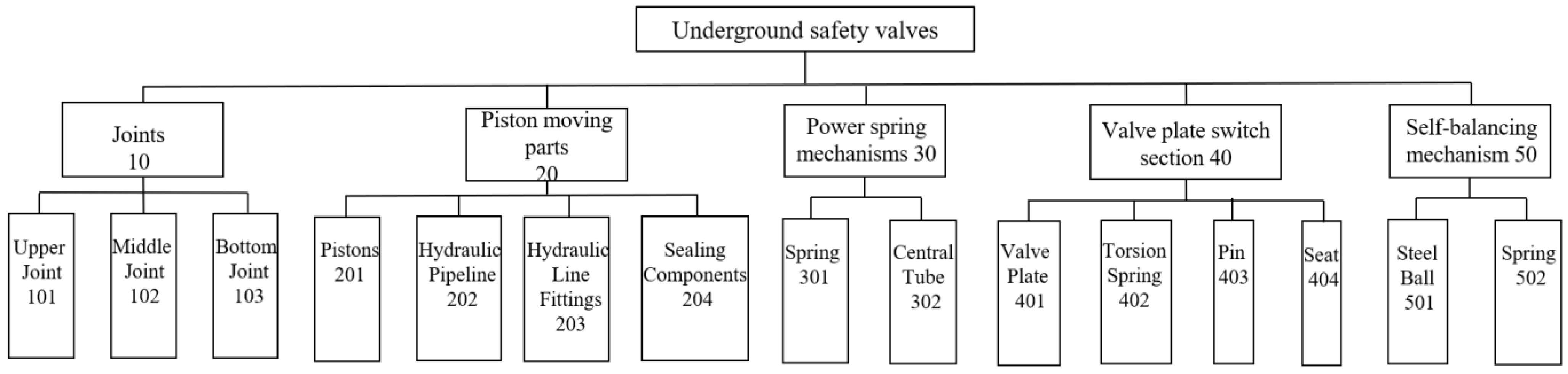
2.2. Hierarchy of Appointments
2.3. FMECA Risk Evaluation Indicators
2.3.1. Classification of Failure Consequences
2.3.2. Failure Probability Classification
2.3.3. Risk Evaluation Index Matrix
2.4. Analysing Results
3. Failure Analysis of Downhole Safety Valve Based on Bow-Tie
3.1. Bow-Tie Method
3.2. Bow-Tie Failure Model for Downhole Safety Valves
4. Quantitative Assessment of Downhole Safety Valve Failure Risk
4.1. Improving the DEMATEL Method
4.1.1. Modelling the Cluster Decision
4.1.2. Group Decision DEMATEL Modelling
4.1.3. Building a Comprehensive Impact Matrix
4.1.4. Calculation of the Fourth Degree
4.2. Quantitative Assessment of the Failure Risk of Subsurface Safety Valves
4.3. Critical Failure Factor Prevention
- (1)
- From the results of the four-degree calculation in the DEMATEL method, it can be seen that the factor that has the greatest influence on the degree of centrality is spring failure. Existing safety valve designs have technical objective defects, resulting in downhole safety valves not meeting the design life indicators. Most of the existing designs rely only on the spring to push the centre tube to open the safety valve, and there is no corresponding redundancy design; once the spring fails, it will directly lead to the failure of the downhole safety valve. Therefore, optimising the structural design of downhole safety valves and improving the manufacturing process have the greatest impact on the service life of safety valves. Design and manufacturing determines the upper limit of the reliability of the downhole safety valve. Underground safety valve design and manufacturing involves: mechanical, hydraulic, sealing, fluid, materials, and other professional disciplines; determining the impact of complex factors; consideration of the sealing and reliability of the piston movement part with high temperature and high pressure; and a need to solve the gate switch part of the hard sealing problem. Also, the joint part of the thread machining accuracy has a direct impact on the performance indicators of the underground safety valve. At present, there is still a big gap between domestic downhole safety valve design experience and proprietary inspection equipment and that of foreign countries, and further research and development efforts are needed.
- (2)
- Based on the analysis results of the Bow-tie method, it can be seen that the main failure modes of downhole safety valves are opening failure and closing failure. It is necessary to set up a high-efficiency field management team, continuously carry out equipment operation and maintenance management training, and establish a field failure response mechanism. In case of failure to open, it is necessary to strictly implement opening operation procedures and, at the same time, ensure the pressure balance between the top and bottom of the safety valve, and if necessary, cooperate with the fracturing pump to balance the oil pressure. For the failure of closure, on the one hand, it is necessary to cancel the operation in the tubing and carry out well risk assessment, and at the same time, it is necessary to formulate monitoring measures, so as to avoid major catastrophic accidents due to the failure of the safety barrier. Field research found that tubing leakage and tubing gas stringing are also two common failure modes in the field. Pipeline cascading is caused by sealing problems in the piston dynamic sealing components, resulting in the leakage of sulphur-containing natural gas in the pipeline through the piston sealing components to the control pipeline and the sulphur-containing natural gas displacing the hydraulic oil and then entering the control cabinet tank or the manual pump on the ground. In view of these failure modes, field management personnel should actively modify the equipment and establish corresponding management countermeasures; at the same time, they should continue to carry out training on downhole safety valves and ancillary systems and continuously improve the field operation level and emergency response capability.
- (3)
- An intelligent operation and maintenance management platform for downhole safety valves should be established. As the downhole safety valve arrangement needs to be lowered into the wellhead, it can not be detected by manual inspection the first time a fault occurs. At present, the field mainly relies on control pressure and oil pressure monitoring data to manually judge the operation status of downhole safety valves. This is a very traditional and inefficient way of equipment management. The rapid development of computers in recent years has provided a new solution for the health monitoring of mechanical equipment. When the downhole safety valve fails, relying on artificial intelligence algorithms to process the signal data, the mechanical failure hidden in the weak signal fluctuations can be detected in time. The application of information technology in the intelligent operation and maintenance management of underground safety valves should be actively explored to achieve visual, scientific, and intelligent management of underground safety valves.
5. Conclusions and Discussion
5.1. Conclusions
- (1)
- Based on the FMECA method, the failure modes, failure impacts, and severity levels were obtained for five subsystems and fifteen components, including the safety valve connector part, the piston movement part, the power spring mechanism, the gate switching part, and the self-balancing mechanism. The FMECA table (shown in Table 5, Table 6, Table 7, Table 8, Table 9, Table 10, Table 11, Table 12 and Table 13) was obtained to classify the failure modes and facilitate the design of improvement measures.
- (2)
- The Bow-tie method clearly revealed the causes of failure and the consequences of accidents caused by downhole safety valves, laying the foundation for quantitative risk analysis. When a failure occurs, site managers can quickly locate the cause of the failure and take appropriate measures according to the Bow-tie model of the downhole safety valve.
- (3)
- The group DEMATEL model based on fuzzy theory was improved, the language scoring method was adopted, the evaluation results of multiple experts were integrated, and the subjectivity of the expert evaluation results was eliminated. We identified six high-risk failure influencing factors of downhole safety valves such as spring failure, failure of corrosion control measures, overloading or substandard performance, material defects, corrosive environments, improper operation at the time of installation, and so on, which provides theoretical guidance to the formulation of on-site management measures.
- (4)
- In order to eliminate or minimise the risk of failure of downhole safety valves, risk prevention measures were proposed from the perspectives of designing and manufacturing, as well as operation and maintenance management, which provide certain references for further improving the design theory of downhole safety valves, as well as improving the integrity management level.
5.2. Discussion
Author Contributions
Funding
Institutional Review Board Statement
Informed Consent Statement
Data Availability Statement
Conflicts of Interest
References
- Aldridge, D. Improving subsurface safety valve reliability: A problem/solution approach. Offshore 1997, 57, 82. [Google Scholar]
- Li, M.; Yang, K.; Zhao, J.; Luo, J.; Li, N. One-way fluid-solid coupling analysis of subsurface safety valve plate. Int. J. Heat Technol. 2018, 36, 433–438. [Google Scholar] [CrossRef]
- Alisjabana, J.M.M.; Shoushtari, M.A.; Ismail, A.; Saaid, M. Improved Lifetime Pressure Drop Management for Subsurface Safety Valves in Oil and Gas Wells. Res. J. Appl. Sci. Eng. Technol. 2013, 5, 727–737. [Google Scholar] [CrossRef]
- Busch, J.M. Subsurface Safety Valves: Safety Asset or Safety Liability? J. Pet. Technol. 1985, 37, 1813–1818. [Google Scholar] [CrossRef]
- Ali, M.A.; Abdulrahman, A.S. Large-bore, HP tubing-retrievable safety valves Qualified for gas wells. World Oil 2013, 234, 85–94. [Google Scholar]
- Champion, B.P.; Gandini, G.; Gabbiani, A. Development and qualification of a new wirelessly controlled retrofit safety valve: An alternative to well work-over that enhances well safety and maximizes production uptime. SPE Prod. Oper. 2010, 26, 111–119. [Google Scholar] [CrossRef]
- Hill, T.H.; Gordon, J.R.; Warner, D.G. A New Completion System for Surface-Controlled Subsurface Safety Valves. J. Pet. Technol. 1974, 26, 331–336. [Google Scholar] [CrossRef]
- Imbò, P.; Gandini, G. Electro Magnetic Wireline Retrievable-Surface Controlled Subsurface Safety Valve: A New Backup For Surface Controlled Subsurface Safety Valve To Avoid Workover. J. Pet. Res. Stud. 2011, 278, 1–21. [Google Scholar] [CrossRef]
- Yuan, G.; Wang, Y.; Fang, Y.; Ma, R.; Ning, K.; Tang, Y. High-Temperature and Pressure Downhole Safety Valve Performance Envelope Curve Study. Processes 2023, 11, 2525. [Google Scholar] [CrossRef]
- Luo, H.; Hu, S.; Lei, Z.; Li, H.; Yang, H.; Tang, H. Analysis on Failure cause of downhole safety valve. Pet. Petrochem. Mater. Procure. 2020, 8, 52. [Google Scholar]
- Zhang, J.; Shao, Y.; Jia, C.; Nie, Z.; Xiao, C.; Lan, H. Countermeasures and Field Practice for the Failure of Downhole Safety Valves in High Sour Gas Wells. Nat. Gas Technol. Econ. 2018, 1, 32–34. [Google Scholar]
- Rausand, M.; Vatn, J. Reliability modeling of surface controlled subsurface safety valves. Reliab. Eng. Syst. Saf. 1998, 61, 159–166. [Google Scholar] [CrossRef]
- Zhang, Z.; Zhao, Y.; Wu, Y.; Deng, H.; Lu, Q. Integrity of Subsurface Safety Valve in Shale Gas Well. Pet. Tubul. Goods Instrum. 2020, 4, 56–62. [Google Scholar]
- Pang, J.; Pu, C.; Wang, W.; Wang, Z. Probability analysis of urban underground sewage pipeline failure based on Bayesian network. Water Supply Drain. 2018, 44, 129–133. [Google Scholar]
- Wang, H.; Zhao, D.; Meng, Y.; Ji, C. Dynamic Risk Assessment of Tank Oil Spill Based on Leading Events and Bayesian Networks. J. Saf. Environ. 2018, 18, 446–450. [Google Scholar]
- He, H. Risk assessment of wellbore integrity based on multi factor coupling. Sci. Technol. Work. Saf. China 2017, 13, 168–172. [Google Scholar]
- Geng, X.; Zhang, Y. Improved FMEA risk assessment method based on hesitant Fuzzy set. Comput. Integr. Manuf. Syst. 2017, 23, 340–348. [Google Scholar]
- Qiu, Z.; Liang, W.; Wang, X.; Lin, Y.; Zhang, M. Real time quantitative risk assessment model for oil and gas transportation equipment. Chin. J. Saf. Sci. 2020, 30, 106–112. [Google Scholar]
- Chen, L.; Jin, L.; Huang, B.; Cao, W.; Wang, X. Bow tie Quantitative Analysis of Tank Leakage Risk Based on a 2D Cloud Model. J. Saf. Environ. 2020, 20, 809–815. [Google Scholar]
- Yu, X.; Jia, P.; Zhang, X. Quantitative risk assessment of urban gas pipeline leakage based on fuzzy BOW-TIE model. Nat. Gas Ind. 2013, 134–139. [Google Scholar]
- Chen, Y.; Jiang, H.; Wu, Y.; Yao, X. Research on risk assessment method of urban Oil pipeline based on Bow tie model. China Sci. Technol. Work. Saf. 2016, 12, 148–152. [Google Scholar]
- Chen, J. Research on the Application of Analytic Hierarchy Process in Safety Evaluation of Petrochemical Enterprises. China High Tech Zone 2019, 258–259. [Google Scholar]
- Zhu, Y.; Meng, Z.; Kan, S. Calculate weights using Analytic Hierarchy Process. J. Beijing Jiaotong Univ. 1999, 119–123. [Google Scholar]
- Li, J.; Xiang, H.; Yan, Y.; Li, Z. A Combination Weighting Evaluation Method Based on Maximizing Deviation and Its Application. Firepower Command. Control. 2020, 45, 18–23. [Google Scholar]
- Karetnikov, V.; Danilov, O.; Kosyak, Y.V.; Rudiyh, S.V. Application of the expert assessment method in developing a navigation safety system for unmanned vessels. J. Physics Conf. Ser. 2021, 2032, 012084. [Google Scholar] [CrossRef]
- Song, S.; Left, Z. Weight analysis of social risk assessment indicators based on DEMATEL-ANP and entropy weight. J. Dalian Jiaotong Univ. 2016, 37, 1–5. [Google Scholar]
- Li, Q.; Duan, W.; Xu, G. Research on Risk Factors of Comprehensive Pipe Corridor Operation and Maintenance Management Based on DEMATEL. Tunn. Constr. 2019, 39, 31–39, (In Chinese and English). [Google Scholar]
- Pacana, A.; Siwiec, D. Method of Fuzzy Analysis of Qualitative-Environmental Threat in Improving Products and Processes (Fuzzy QE-FMEA). Materials 2023, 16, 1651. [Google Scholar] [CrossRef] [PubMed]
- Opricovic, S.; Tzeng, G.-H. Defuzzification within a multicriteria decision model. Int. J. Uncertain. Fuzziness Knowl.-Based Syst. 2003, 11, 635–652. [Google Scholar] [CrossRef]


| Failure Consequence Category | Instructions |
|---|---|
| I | Cause the failure of other equipment or complete loss of function of the subsystem or constitute a safety hazard affecting the functioning of the unit |
| II | Total loss or serious degradation |
| III | Resulting in a general downgrading of the work capacity of the module |
| IV | Result in small or negligible impacts on this module |
| Level | Degree | Probability |
|---|---|---|
| A | Happens all the time | The probability of this failure mode occurring during the product’s operating period is high. The probability of occurrence of a single failure mode is greater than 20 percent of the total probability of failure of the product during that period. |
| B | Likely to happen | The probability of this failure mode occurring during the product’s operating period is moderate. The probability of occurrence of a single failure mode is 10 to 20 percent of the total probability of failure of the product during that period. |
| C | Happen by chance | The failure mode occurs by chance during the product’s operating period. The probability of occurrence of a single failure mode is 1 to 10 percent of the total probability of failure of the product during that period. |
| D | Rarely happen | The failure mode is unlikely to occur during product operation. The probability of occurrence of a single failure mode is 0.1 to 1 percent of the total probability of failure of the product during that period. |
| E | Unlikely to happen | The probability of this failure mode occurring during the operation of the product is almost zero. The probability of occurrence of a single failure mode is less than 0.1 percent. |
| Risk Index | Severity of Danger Level | ||||
|---|---|---|---|---|---|
| I | II | III | IV | ||
| Probability of danger | A | 1 | 3 | 7 | 13 |
| B | 2 | 5 | 9 | 16 | |
| C | 4 | 6 | 11 | 18 | |
| D | 8 | 10 | 14 | 19 | |
| E | 12 | 15 | 17 | 20 | |
| Risk Index | Severity of Danger Level | Principles of Treatment |
|---|---|---|
| 1~5 | Very high | Unacceptable and measures must be taken to eliminate or reduce it to an acceptable level |
| 6~9 | High | Conditional acceptance and targeted measures |
| 10~17 | Moderate | Acceptable after review or approval |
| 18~20 | Low | Acceptable |
| Number | Code | Name | Function | Failure Mode | Failure Reason | Impact | Test Method | Improvements and Measures | Severity Level | Probability Level | Risk Assessment | Note | ||
|---|---|---|---|---|---|---|---|---|---|---|---|---|---|---|
| Local Impact | Impact on Higher Levels | Final Impact | ||||||||||||
| 1 | 101 | Upper Joint | Connection of the upper fuel line and the line | Break off | Plastic fracture at joints under tensile and torsional loads | Downhole safety valve disconnected from upper tubing | None | None | Signal detection | Improved design of joints; improved materials and machining processes | Ⅰ | E | 15 | |
| Adhesive wear of joints | Excessive torque during cocking | Adhesive wear on step surfaces | Unable to connect upper casing | None | On-the-spot observation | Clean thread and step surfaces and apply thread grease | IV | E | 17 | |||||
| Connection failure | Severe plastic deformation due to striated tooth occurrence | Thread failure | Unable to remove upper casing | None | On-the-spot observation | The use of qualified lubricants, new joints are broken in before being allowed to be put into use | IV | D | 19 | |||||
| Perforated | Corrosion of connectors by corrosive substances | Failure of joint seals | Leakage | Difficulty in opening valves | Signal detection | The joints are made of corrosion-resistant materials | Ⅲ | D | 19 | |||||
| Number | Code | Name | Function | Failure Mode | Failure Reason | Impact | Test Method | Improvements and Measures | Severity Level | Probability Level | Risk Assessment | Note | ||
|---|---|---|---|---|---|---|---|---|---|---|---|---|---|---|
| Local Impact | Impact on Higher Levels | Final Impact | ||||||||||||
| 2 | 102 | Middle Joint | Connection of the upper fuel line and the hydraulic control line | Break off | Mechanical properties of the joint are not up to standard or the load exceeds the permissible stress | Broken connector joints | None | Valve failure | Signal detection | Improved design of joints; improved materials and machining processes | Ⅰ | E | 12 | |
| Adhesive wear of joints | Excessive torque during cocking | Adhesive wear on step surfaces | Unable to connect upper and lower joints | None | On-the-spot observation | Clean thread and step surfaces and apply thread grease | Ⅲ | E | 17 | |||||
| Connection failure | Severe plastic deformation due to striated tooth occurrence | Thread failure | Unable to remove upper casing | None | On-the-spot observation | The use of qualified lubricants, new joints are broken in before being allowed to be put into use | Ⅲ | E | 17 | |||||
| Perforated | Corrosion of connectors by corrosive substances | Failure of joint seals | Leakage | Difficulty in opening valves | Signal detection | The joints are made of corrosion-resistant materials | Ⅳ | D | 19 | |||||
| Number | Code | Name | Function | Failure Mode | Failure Reason | Impact | Test Method | Improvements and Measures | Severity Level | Probability Level | Risk Assessment | Note | ||
|---|---|---|---|---|---|---|---|---|---|---|---|---|---|---|
| Local Impact | Impact on Higher Levels | Final Impact | ||||||||||||
| 3 | 103 | Lower joint | Connecting intermediate joints and lower casing | Break off | Plastic fracture at joints under tensile and torsional loads | Broken connector joints | None | Valve failure | Signal detection | Improved design of joints; improved materials and machining processes | Ⅰ | E | 12 | |
| Adhesive wear of joints | Excessive torque during cocking | Adhesive wear on step surfaces | Unable to connect upper casing | None | On-the-spot observation | Clean thread and step surfaces and apply thread grease | Ⅲ | E | 17 | |||||
| Connection failure | Severe plastic deformation due to striated tooth occurrence | Thread failure | Unable to remove upper casing | None | On-the-spot observation | The use of qualified lubricants, new joints are broken in before being allowed to be put into use | Ⅲ | E | 17 | |||||
| Perforated | Corrosion of connectors by corrosive substances | Failure of joint seals | Leakage | Difficulty in opening valves | Signal detection | The joints are made of corrosion-resistant materials | Ⅲ | D | 19 | |||||
| Number | Code | Name | Function | Failure Mode | Failure Reason | Impact | Test Method | Improvements and Measures | Severity Level | Probability Level | Risk Assessment | Note | ||
|---|---|---|---|---|---|---|---|---|---|---|---|---|---|---|
| Local Impact | Impact on Higher Levels | Final Impact | ||||||||||||
| 4 | 201 | Piston | Transmitting pressure to the spring | Piston jam | High piston friction leads to wear on the outer surface | Unable to transmit hydraulic pressure | Unable to compress the spring to its intended position | Inability to open or close valves | Pressure detection | Regular inspections and high-quality lubricant changes | Ⅱ | A | 3 | |
| Piston Broken | Stress fatigue of the plunger due to alternating stresses | Unable to transmit hydraulic pressure | Inability to promote the centre tube | Valve fails to open | None | Replacement of safety valves | Ⅲ | D | 14 | |||||
| Corrosion and wear of hard sealing surfaces | Wear caused by oil or relative motion | None | Hydraulic oil leakage, system pressure drop | Difficulty in opening valves | Signal detection | Regular replacement of hydraulic oil and safety valves | Ⅳ | C | 18 | |||||
| 5 | 202 | Hydraulic control line | Conveying oils and fluids | Blockage | Clogging of hydraulic lines by impurities | Unable to transmit hydraulic pressure | Inability to promote the centre tube | Inability to open or close valves | Signal detection | Enhanced cleaning and regular filter replacement | Ⅱ | D | 10 | |
| Number | Code | Name | Function | Failure Mode | Failure Reason | Impact | Test Method | Improvements and Measures | Severity Level | Probability Level | Risk Assessment | Note | ||
|---|---|---|---|---|---|---|---|---|---|---|---|---|---|---|
| Local Impact | Impact on Higher Levels | Final Impact | ||||||||||||
| 6 | 203 | Hydraulic control line joints | Connecting the hydraulic control line and the corresponding connector | Joint unplugged | Poor parameter design, poorly designed joints and sleeves, low buckle volume | Disconnection | Leakage in hydraulic lines | Valve fails to open | Signal detection | Assembly check before going down the shaft to ensure reliability of connections and improve design | Ⅱ | D | 10 | |
| Connector bursts | System pressure exceeds permissible joint pressure | None | Leakage in hydraulic lines | Valve fails to open | Signal detection | Prevents pressure exceeding the permissible joint pressure | Ⅱ | E | 15 | |||||
| Oil seepage at buckling point | Large deviation of the inner diameter of the hose and the outer diameter of the steel wire layer, uneven thickness and aging deformation of the inner rubber layer | None | Leakage in hydraulic lines | None | Human observation | Strengthen the control of joint parts and improve the processing technology | Ⅳ | B | 16 | |||||
| 7 | 204 | Sealing component | Sealing piston | Reduced strength and elasticity of seals | High temperatures and corrosion cause seals to harden and crack | Fluid leakage at the piston | Hydraulic oil leakage; in severe cases the system pressure drops | Difficulty in opening valves | Signal detection | Regularly check piston seals; replace safety valves in severe cases | Ⅲ | D | 14 | |
| Number | Code | Name | Function | Failure Mode | Failure Reason | Impact | Test Method | Improvements and Measures | Severity Level | Probability Level | Risk Assessment | Note | ||
|---|---|---|---|---|---|---|---|---|---|---|---|---|---|---|
| Local Impact | Impact on Higher Levels | Final Impact | ||||||||||||
| 8 | 301 | Spring | Promotion of centre tube | Spring breakage | High piston friction leads to wear on the outer surface | Inability to promote the centre tube | Centre tube rollback | Failure to open the valve | Signal detection | Check the working condition of the spring and replace it when appropriate | Ⅲ | B | 9 | |
| Spring fatigue relaxation | Stress fatigue of the plunger due to alternating stresses | Reduced elasticity on the centre tube | Centre tube rollback | Affects valve action | Signal detection | Pre-tension the spring and replace it when appropriate | Ⅲ | C | 11 | |||||
| Corrode | Wear caused by oil or relative motion | Reduced elasticity on the centre tube | Centre tube rollback | Affects valve action | Signal detection | Apply antirust substance to the spring and replace it in case of severe condition | Ⅱ | E | 15 | |||||
| 9 | 302 | Switchboard | Push balls and valves | Damage to sealing surface | Clogging of hydraulic lines by impurities | Increased friction with the casing and inability to open the valve | Affects ball and valve motion | Difficulty in opening valves | Signal detection | Apply antirust substance to the spring and replace it in case of severe condition | Ⅲ | B | 9 | |
| Deformity | High downhole pressure | Increased friction with the casing and inability to open the valve | Affects ball and valve motion | Impurities from scratching prevent the valve from closing completely | None | The surface of the centre tube is shot peened to improve surface hardness | Ⅲ | C | 11 | |||||
| Impurity jamming | Impurities or crystals on sealing surface | Increased friction with the casing and inability to open the valve | Affects ball and valve motion | Affects valve motions | Signal detection | Use corrosion-resistant alloy to make the centre tube and replace it in case of seriousness | Ⅲ | D | 14 | |||||
| Number | Code | Name | Function | Failure Mode | Failure Reason | Impact | Test Method | Improvements and Measures | Severity Level | Probability Level | Risk Assessment | Note | ||
|---|---|---|---|---|---|---|---|---|---|---|---|---|---|---|
| Local Impact | Impact on Higher Levels | Final Impact | ||||||||||||
| 10 | 401 | Switchboard | Close the channel | Damage to sealing surface | Corroded gate or fluid impact | Leakage | Plate and seat cannot seal completely | Valve leakage | Signal detection | Spray anti-corrosion coating on the surface of the valve plate and replace it in time | Ⅰ | B | 2 | |
| Deformity | High downhole pressure | Leakage | Valve seal failure | Valve fails to seal | Signal detection | Choose the right model and increase the size appropriately | Ⅰ | D | 8 | |||||
| Impurity jamming | Impurities or crystals on sealing surface | Leakage | Plate and seat cannot seal completely | Valve leakage | Signal detection | Improved centre tube design to avoid fluid shock when opening the valve | Ⅱ | D | 10 | |||||
| 11 | 402 | Torsion spring | Driving the gate to close | Torque reduction | Long-term exposure of springs to corrosive fluids | Leakage | The gate cannot be retracted | The valve fails to seal the well | Signal detection | Increase design size and replace periodically | Ⅰ | D | 8 | |
| Break off | Plastic deformation due to alternating stress and eventual fracture | Leakage | The gate cannot be retracted | The valve fails to seal the well | Signal detection | Regular replacement | Ⅰ | E | 12 | |||||
| Corrode | Corrosion in humid environments | Leakage | The gate cannot be retracted | The valve fails to seal the well | Signal detection | Improved materials, regular replacement | Ⅰ | E | 12 | |||||
| Number | Code | Name | Function | Failure Mode | Failure Reason | Impact | Test Method | Improvements and Measures | Severity Level | Probability Level | Risk Assessment | Note | ||
|---|---|---|---|---|---|---|---|---|---|---|---|---|---|---|
| Local Impact | Impact on Higher Levels | Final Impact | ||||||||||||
| 12 | 403 | Pin | Connecting the gate to the valve seat | Break off | Load exceeding permissible stress | Unable to connect the gate | Dislodged gate | The valve fails to seal the well | Signal detection | Improved processing and regular replacement | Ⅱ | D | 10 | |
| Corrode | Corrosion in humid environments | Pin outer diameter decreases, strength decreases | Dislodged gate | Affects valve action | Human observation | Use of qualified lubricants, regular maintenance | Ⅰ | E | 12 | |||||
| 13 | 404 | Valve seat | Balance the upper and lower pressure and form a seal with the valve plate | Blockage | The gap between the valve seat and the lower fitting is blocked by impurities | None | Upper and lower pressures are not balanced when the valve is opened | Valves failing to open | Signal detection | Regularly open and close the valve to ensure that the counterbalance valve can properly relieve the pressure | Ⅱ | B | 5 | |
| Number | Code | Name | Function | Failure Mode | Failure Reason | Impact | Test Method | Improvements and Measures | Severity Level | Probability Level | Risk Assessment | Note | ||
|---|---|---|---|---|---|---|---|---|---|---|---|---|---|---|
| Local Impact | Impact on Higher Levels | Final Impact | ||||||||||||
| 14 | 501 | Steel ball | Controls the balance of pressure on the top and bottom of the gate | Corrode | Corrosion in corrosive environments | Leakage from sealing with the inner cone of the valve seat | Impact on valve sealing function | Leakage | Signal detection | Selection of corrosion-resistant materials | Ⅲ | C | 11 | |
| Surface scratching | Centre tube edge scratches | Unable to seal high-pressure downhole | Inability to balance upper and lower pressure | Leakage | Signal detection | Improved design of the lower outer edge of the centre tube | Ⅲ | D | 14 | |||||
| Ball deformation | Deformation under downhole pressure | Unable to seal high-pressure downhole | Inability to balance upper and lower pressure | Leakage | Signal detection | Shot peening of the surface and selection of high-strength materials | Ⅲ | D | 14 | |||||
| 15 | 502 | Springlets | Push steel balls | Spring fatigue relaxation | Long-term force on springs | Loss of elasticity | None | None | Signal detection | Pre-tensioned and replaced in a timely manner | Ⅳ | B | 16 | |
| Corrode | Corrosion in corrosive environments | Corrosion in corrosive environments | None | None | Signal detection | Surface coated with antirust substance | Ⅳ | C | 18 | |||||
| Designator | Events | Designator | Events | Designator | Events |
|---|---|---|---|---|---|
| M1 | Seal leaks | C5 | Piston failure | X6 | Pin failure |
| M2 | Failure to close | C6 | Upper connector connection failure | X7 | Torsion spring failure |
| M3 | Failure to open | C7 | Intermediate joint connection failure | X8 | Steel ball failure |
| M4 | Early closure | C8 | Lower connector connection failure | X9 | Spring failure |
| M5 | Connection failure | X1 | Material defects | X10 | Ground pipe rupture |
| C1 | Damage to valve seat, valve body | X2 | Improper handling during installation | X11 | Blocked ground pipes |
| C2 | Corrosion | X3 | Seal surface damage or foreign objects | X12 | Pipeline pull off |
| C3 | Failure of executing agency | X4 | Failure of anti-corrosion measures | X13 | Hydraulic oil circuit seal failure |
| C4 | Ground control unit failure | X5 | Corrosive environments | X14 | Overload or substandard performance |
| Fuzzy Numbers | |
|---|---|
| (0, 0, 0.25) | |
| (0, 0.25, 0.5) | |
| (0.25, 0.5, 0.75) | |
| (0.5, 0.75, 1) | |
| (0.75, 1, 1) |
| Risk Factors | Risk Factors | |||||||||||||
|---|---|---|---|---|---|---|---|---|---|---|---|---|---|---|
| Risk Factors | Four Degree Indicator | |||||
|---|---|---|---|---|---|---|
| Degree of Impact | Degree of Being Influenced | Sort by Centrality | Reason Degree Ranking | |||
| 4.22 | 0.14 | 4.36 | 4 | 4.08 | 1 | |
| 3.18 | 0 | 3.18 | 6 | 3.18 | 4 | |
| 1.10 | 0.89 | 1.99 | 12 | 0.21 | 9 | |
| 4.33 | 1.1 | 5.43 | 2 | 3.23 | 3 | |
| 3.56 | 0 | 3.56 | 5 | 3.56 | 2 | |
| 0.78 | 1.65 | 2.43 | 11 | −0.87 | 12 | |
| 0.81 | 1.65 | 2.46 | 9 | −0.84 | 11 | |
| 0.98 | 1.98 | 2.96 | 8 | −1 | 13 | |
| 5.13 | 2.21 | 7.34 | 1 | 2.92 | 5 | |
| 0.83 | 0.61 | 1.44 | 13 | 0.22 | 8 | |
| 0.78 | 0.61 | 1.39 | 14 | 0.17 | 10 | |
| 0.65 | 1.78 | 2.43 | 10 | −1.13 | 14 | |
| 2.37 | 0.68 | 3.05 | 7 | 1.69 | 6 | |
| 2.82 | 1.7 | 4.52 | 3 | 1.12 | 7 | |
Disclaimer/Publisher’s Note: The statements, opinions and data contained in all publications are solely those of the individual author(s) and contributor(s) and not of MDPI and/or the editor(s). MDPI and/or the editor(s) disclaim responsibility for any injury to people or property resulting from any ideas, methods, instructions or products referred to in the content. |
© 2024 by the authors. Licensee MDPI, Basel, Switzerland. This article is an open access article distributed under the terms and conditions of the Creative Commons Attribution (CC BY) license (https://creativecommons.org/licenses/by/4.0/).
Share and Cite
Yuan, G.; Wang, Y.; Yang, X.; Fang, Y.; Ma, R.; Ning, K.; Guan, M.; Tang, Y. Study on Quantitative Evaluation Method for Failure Risk Factors of the High-Temperature and High-Pressure Downhole Safety Valve. Sustainability 2024, 16, 1896. https://doi.org/10.3390/su16051896
Yuan G, Wang Y, Yang X, Fang Y, Ma R, Ning K, Guan M, Tang Y. Study on Quantitative Evaluation Method for Failure Risk Factors of the High-Temperature and High-Pressure Downhole Safety Valve. Sustainability. 2024; 16(5):1896. https://doi.org/10.3390/su16051896
Chicago/Turabian StyleYuan, Guohai, Yonghong Wang, Xingguo Yang, Yexin Fang, Rutao Ma, Kun Ning, Miantao Guan, and Yang Tang. 2024. "Study on Quantitative Evaluation Method for Failure Risk Factors of the High-Temperature and High-Pressure Downhole Safety Valve" Sustainability 16, no. 5: 1896. https://doi.org/10.3390/su16051896