
On-Machine Measurement as a Factor Affecting the Sustainability of the Machining Process

 , ,
, ,  ,
,  and
and
Abstract
1. Introduction
2. Materials and Methods
3. Results and Discussion
4. Conclusions
- Measurements taken with the strain gauge probe feature about 65% lower measurement uncertainty values than with the kinematic resistive probe, ignoring the impact of returning the probe to the tool magazine. In the case of both probes, satisfactory results were obtained, allowing them to be successfully used interchangeably with classic, manual measuring instruments. This saves resources because a number of devices and gauges are replaced with a universal probe.
- Eliminating manual measurements shortens the process and thus saves energy. It also represents a health benefit for the operator, as each time the machine is opened, toxic fumes from the coolant are released and enter the respiratory system.
- Improving process quality through the use of probing reduces the number of scrap parts. This results in a reduction in the consumption of resources such as workpiece material and cutting tools for rework. Avoiding corrections or reworking an entire part means eliminating power consumption.
- Putting the probe in the tool magazine has a negative effect on the repeatability of measurements (2σ increase by 125% for RMP40M+LP2 and by 50% for RMP600). The direction of measurement affects the accuracy of the results obtained (2σ received two times higher for the Z-axis than the Y-axis).
- Several hours of machine tool downtime caused significant differences in the results obtained for measuring the same feature. The value of the measured diameter decreased by 7 µm.
Author Contributions
Funding
Institutional Review Board Statement
Informed Consent Statement
Data Availability Statement
Acknowledgments
Conflicts of Interest
Nomenclature
| 2σ | twice standard deviation |
| σ | standard deviation |
| Ø | diameter symbol |
| Avg. | average |
| CNC | computerized numerical control |
| CMM | coordinate measuring machine |
| D1 | tool offset number 1 in Sinumerik controller |
| D2 | tool offset number 2 in Sinumerik controller |
| L | length |
| Max. | maximum |
| Min. | minimum |
| U | measurement uncertainty |
References
- Hamrol, A.; Gawlik, J.; Sładek, J. Mechanical Engineering In Industry 4.0. Manag. Prod. Eng. Rev. 2019, 10, 19–28. [Google Scholar] [CrossRef]
- Takaya, Y. In-Process and On-Machine Measurement of Machining Accuracy for Process and Product Quality Management: A Review. Int. J. Autom. Technol. 2013, 8, 4–19. [Google Scholar] [CrossRef]
- Majstorovic, V.D.; Durakbasa, N.; Takaya, Y.; Stojadinovic, S. Advanced Manufacturing Metrology in Context of Industry 4.0 Model. In Proceedings of the 12th International Conference on Measurement and Quality Control—Cyber Physical Issue. IMEKOTC14, Belgrade, Serbia, 4–7 June 2019; Lecture Notes in Mechanical Engineering. Majstorovic, V., Durakbasa, N., Eds.; Springer: Cham, Switzerland, 2019. [Google Scholar] [CrossRef]
- Horst, J.; Hedberg, T.; Feeney, A.B. On-machine measurement use cases and information for machining operations. Natl. Inst. Stand. Technol. Adv. Man. Ser. 2019, 400–401, 1–69. [Google Scholar] [CrossRef]
- Woźniak, A.; Męczyńska, K. Measurement hysteresis of touch-trigger probes for CNC machine tools. Measurement 2020, 156, 107568. [Google Scholar] [CrossRef]
- Szablewski, P.; Legutko, S.; Mróz, A.; Garbiec, D.; Czajka, R.; Smak, K.; Krawczyk, B. Surface Topography Description after Turning Inconel 718 with a Conventional, Wiper and Special Insert Made by the SPS Technique. Materials 2023, 16, 949. [Google Scholar] [CrossRef]
- Guerra, M.; Coelho, R.T. Development of a low cost Touch Trigger Probe for CNC Lathes. J. Mater. Process. Technol. 2006, 179, 117–123. [Google Scholar] [CrossRef]
- Koleva, S.; Enchev, M.; Szecsi, T. Automatic Dimension Measurement on CNC Lathes Using the Cutting Tool. Procedia CIRP 2015, 33, 568–575. [Google Scholar] [CrossRef]
- Bomba, G.; Ornat, A.; Gierlak, P.; Muszynska, M. On-Machine Measurements for Aircraft Gearbox Machining Process Assisted by Adaptive Neuro-Fuzzy Inference System. Appl. Sci. 2022, 12, 4780. [Google Scholar] [CrossRef]
- Szyszka, G.; Sep, J. Comparative Performance Evaluation of Multiconfiguration Touch-Trigger Probes for Closed-Loop Machining of Large Jet Engine Cases. Materials 2022, 15, 1461. [Google Scholar] [CrossRef] [PubMed]
- Jankowski, M.; Wozniak, A.; Mayer, J.R.R. On-machine and In-laboratory Investigation of Errors of Probes for CNC Machine Tools. In Advances in Engineering Research and Application. ICERA; Lecture Notes in Networks and Systems; Fujita, H., Nguyen, D., Vu, N., Banh, T., Puta, H., Eds.; Springer: Cham, Switzerland, 2018; Volume 63. [Google Scholar] [CrossRef]
- Achelker, C.; Srinivasa Rao, N.; Rajendra, R.; Krishaniah, A. Performance Evaluation of Machine Tool Probe for In-process Inspection of 2D and 3D Geometries. Procedia Technol. 2014, 14, 244–251. [Google Scholar] [CrossRef]
- Jankowski, M.; Wozniak, A. Mechanical model of errors of probes for numerical controlled machine tools. Measurement 2016, 77, 317–326. [Google Scholar] [CrossRef]
- Mutilba, U.; Gomez-Acedo, E.; Kortaberria, G.; Olarra, A.; Yagüe-Fabra, J.A. Traceability of On-Machine Tool Measurement: A Review. Sensors 2017, 17, 1605. [Google Scholar] [CrossRef]
- Woźniak, A.; Dobosz, A. Influence of measured objects parameters on CMM touch trigger probe accuracy of probing. Precis. Eng. 2005, 29, 290–297. [Google Scholar] [CrossRef]
- Kuo, C.-H.; Chen, P.-C. On-Machine Measurement and Error Compensation for 6061 Aluminum Alloy Hexagonal Punch Using a Turn-Milling Machine. Machines 2021, 9, 180. [Google Scholar] [CrossRef]
- Holub, M.; Jankovych, R.; Andrs, O.; Kolibal, Z. Capability Assessment of CNC Machining Centres as Measuring Devices. Measurement 2018, 118, 52–60. [Google Scholar] [CrossRef]
- Jankowski, M.; Wozniak, A. Testing of the delay time of wireless communication of cnc machine tools` probes and controller. Metrol. Meas. Syst. 2018, 25, 377–386. [Google Scholar] [CrossRef]
- Woźniak, A.; Byszewski, M.; Jankowski, M. 3D characteristics of triggering force of CNC machine tool probe. J. Phys. Conf. Ser. 2018, 1065, 142014. [Google Scholar] [CrossRef]
- Wieczorowski, M.; Trojanowska, J. Towards Metrology 4.0 In Dimensional Measurements. J. Mach. Eng. 2023, 23, 100–113. [Google Scholar] [CrossRef]
- Senin, N.; Leach, R. Information-rich surface metrology. Procedia Cirp 2018, 75, 19–26. [Google Scholar] [CrossRef]
- Fernando, R.; Gamage, J.; Karunathilake, H. Sustainable machining: Environmental performance analysis of turning. Int. J. Sustain. Eng. 2023, 15, 15–34. [Google Scholar] [CrossRef]
- Pimenov, D.; Mia, M.; Gupta, M.; Machado, A.; Pintaude, G.; Unune, D.; Khanna, N.; Khan, A.; Tomaz, I.; Wojciechowski, S.; et al. Resource saving by optimization and machining environments for sustainable manufacturing: A review and future prospects. Renew. Sustain. Energy Rev. 2022, 166, 112660. [Google Scholar] [CrossRef]
- Venkataravanappa, R.Y.; Lakshmikanthan, A.; Kapilan, N.; Chandrashekarappa, M.P.G.; Der, O.; Ercetin, A. Physico-Mechanical Property Evaluation and Morphology Study of Moisture-Treated Hemp–Banana Natural-Fiber-Reinforced Green Composites. J. Compos. Sci. 2023, 7, 266. [Google Scholar] [CrossRef]
- Lucato, W.C.; Santos, J.C.d.S.; Pacchini, A.P.T. Measuring the Sustainability of a Manufacturing Process: A Conceptual Framework. Sustainability 2018, 10, 81. [Google Scholar] [CrossRef]
- Kumar, R.; Sharma, S.; Kumar, R.; Verma, S.; Rafighi, M. Review of Lubrication and Cooling in Computer Numerical Control (CNC) Machine Tools: A Content and Visualization Analysis, Research Hotspots and Gaps. Sustainability 2023, 15, 4970. [Google Scholar] [CrossRef]
- Krolczyk, G.M.; Maruda, R.W.; Krolczyk, J.B.; Wojciechowski, S.; Mia, M.; Nieslony, P.; Budzik, G. Ecological trends in machining as a key factor in sustainable production—A review. J. Clean. Prod. 2019, 218, 601–615. [Google Scholar] [CrossRef]
- Peng, Z.; Zhang, X.; Liu, L.; Xu, G.; Wang, G.; Zhao, M. Effect of high-speed ultrasonic vibration cutting on the microstructure, surface integrity, and wear behavior of titanium alloy. J. Mater. Res. Technol. 2023, 24, 3870–3888. [Google Scholar] [CrossRef]
- Peng, Z.; Zhang, X.; Zhang, Y.; Liu, L.; Xu, G.; Wang, G.; Zhao, M. Wear resistance enhancement of Inconel 718 via high-speed ultrasonic vibration cutting and associated surface integrity evaluation under high-pressure coolant supply. Wear 2023, 530–531, 205027. [Google Scholar] [CrossRef]
- Brillinger, M.; Wuwer, M.; Hadi, M.A.; Haas, F. Energy prediction for CNC machining with machine learning. CIRP J. Manuf. Sci. Technol. 2021, 35, 715–723. [Google Scholar] [CrossRef]
- Jia, S.; Wang, S.; Lv, J.; Cai, W.; Zhang, N.; Zhang, Z.; Bai, S. Multi-Objective Optimization of CNC Turning Process Parameters Considering Transient-Steady State Energy Consumption. Sustainability 2021, 13, 13803. [Google Scholar] [CrossRef]
- Belhadi, A.; Kamble, S.S.; Zkik, K.; Cherrafi, A.; Touriki, F.E. The integrated effect of Big Data Analytics, Lean Six Sigma and Green Manufacturing on the environmental performance of manufacturing companies: The case of North Africa. J. Clean. Prod. 2020, 252, 119903. [Google Scholar] [CrossRef]
- Krawczyk, B.; Szablewski, P.; Legutko, S.; Smak, K.; Gapinski, B. Anomalies in the Geometric Surface Structure of Shaped Elements Composed of Inconel 718 Alloy. Materials 2021, 14, 7524. [Google Scholar] [CrossRef]
- Mian, S.H.; Al-Ahmari, A. New developments in coordinate measuring machines for manufacturing industries. Int. J. Metrol. Qual. Eng. 2014, 5, 101. [Google Scholar] [CrossRef]
- Krawczyk, B.; Szablewski, P.; Mendak, M.; Gapiński, B.; Smak, K.; Legutko, S.; Wieczorowski, M.; Miko, E. Surface Topography Description of Threads Made with Turning on Inconel 718 Shafts. Materials 2023, 16, 80. [Google Scholar] [CrossRef] [PubMed]
- Lee, Y.C.; Yeh, S.S. Using Machine vision to develop an on-machine thread measurement system for computer numerical control lathe machines. In Proceedings of the Lecture Notes in Engineering and Computer Science: Proceedings of The International MultiConference of Engineers and Computer Scientists, Hong Kong, China, 20–22 October 2021; 2019; Volume 2239, pp. 13–15. [Google Scholar]
- Lee, Y.C.; Wu, Y.C.; Yeh, S.S. Development of an On-Machine External Thread Measurement System for CNC Lathes Using Eye-in-Hand Machine Vision with Morphology Technology. Eng. Lett. 2021, 29, 1–12. [Google Scholar]
- Dong, Z.; Sun, X.; Chen, C.; Sun, M. A Fast and On-Machine Measuring System Using the Laser Displacement Sensor for the Contour Parameters of the Drill Pipe Thread. Sensors 2018, 18, 1192. [Google Scholar] [CrossRef]
- Swojak, N.; Wieczorowski, M.; Jakubowicz, M. Assessment of selected metrological properties of laser triangulation sensors. Measurement 2021, 176, 109190. [Google Scholar] [CrossRef]
- Gąska, A.; Sładek, J.; Gąska, P. Challenges for Uncertainty Determination in Dimensional Metrology Put by Industry 4.0 Revolution. In Proceedings of the 5th International Conference on the Industry 4.0 Model for Advanced Manufacturing, Belgrade, Serbia, 1–4 June 2020; Lecture Notes in Mechanical Engineering. Wang, L., Majstorovic, V., Mourtzis, D., Carpanzano, E., Moroni, G., Galantucci, L., Eds.; Springer: Cham, Switzerland, 2021. [Google Scholar] [CrossRef]
- Jankowski, M.; Woźniak, A.; Byszewski, M. Machine tool probes testing using a moving inner hemispherical master artefact. Precis. Eng. 2014, 38, 421–427. [Google Scholar] [CrossRef]
- Sepahi-Boroujeni, S.; Mayer, R.; Khameneifar, F.; Woźniak, A. A full-covariance uncertainty assessment in on-machine probing. Int. J. Mach. Tools Manuf. 2021, 167, 103768. [Google Scholar] [CrossRef]
- Gherghea, I.C.; Negrău, D.; Bungau, C.; Faur, M. Waste reduction by implementation of CNC machining center and Lean Manufacturing. IOP Conf. Ser. Mater. Sci. Eng. 2020, 898, 012005. [Google Scholar] [CrossRef]
- Renishaw Workpiece Inspection and Tool Setting Probes Help Vasantha Tool Crafts Increase Machine Utilisation Time by 20%. Available online: https://www.renishaw.com/resourcecentre/en/details/--88100 (accessed on 16 December 2023).
- Bomba, G.; Ornat, A.; Gierlak, P. Geometric Measurements on a CNC Machining Device as an Element of Closed Door Technology. Sensors 2021, 21, 4852. [Google Scholar] [CrossRef]
- Benedicto, E.; Carou, D.; Rubio, E.M. Technical, economic and environmental review of the lubrication/cooling systems used in machining processes. Procedia Eng. 2017, 184, 99–116. [Google Scholar] [CrossRef]
- Li, K.; Aghazadeh, F.; Hatipkarasulu, S.; Ray, T.G. Health risks from exposure to metal-working fluids in machining and grinding operations. Int. J. Occup. Saf. Ergon. 2003, 9, 75–95. [Google Scholar] [CrossRef] [PubMed]
- Kiraci, E.; Palit, A.; Donnelly, M.; Attridge, A.; Williams, M.A. Comparison of in-line and off-line measurement systems using a calibrated industry representative artefact for automotive dimensional inspection. Measurement 2020, 163, 108027. [Google Scholar] [CrossRef]


| RMP40M + LP2 | RMP600 | |
|---|---|---|
| Unidirectional repeatability | 1 µm 2σ | 0.25 µm 2σ |
| Stylus trigger force in XY | 0.5 N | 0.2 N |
| View of the probe | 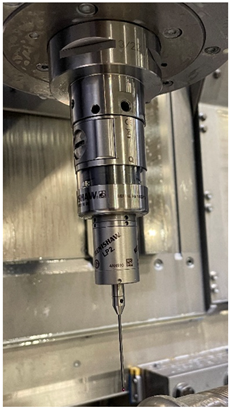 |  |
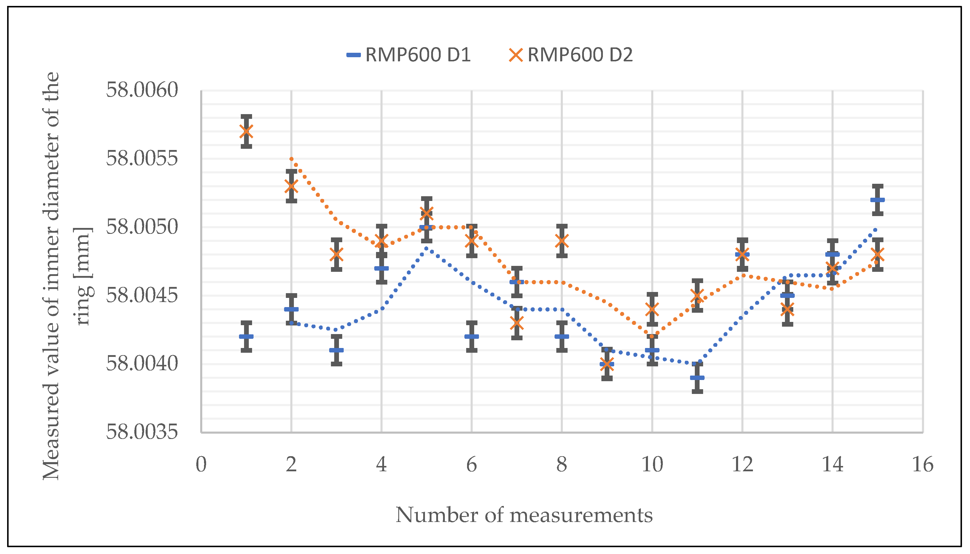
| Avg. [mm] | Min. [mm] | Max. [mm] | Max.–Min. [mm] | σ [mm] | 2σ [mm] | |
|---|---|---|---|---|---|---|
| RMP600 D1 | 58.0044 | 58.0039 | 58.0052 | 0.0013 | 0.0004 | 0.0008 |
| RMP600 D2 | 58.0048 | 58.0040 | 58.0057 | 0.0017 | 0.0004 | 0.0008 |
| Avg. [mm] | Min. [mm] | Max. [mm] | Max.–Min. [mm] | σ [mm] | 2σ [mm] | |
|---|---|---|---|---|---|---|
| Z axis | 58.0036 | 58.0019 | 58.0056 | 0.0037 | 0.0009 | 0.0018 |
| Y axis | 58.0053 | 58.0037 | 58.0061 | 0.0024 | 0.0005 | 0.0009 |
| Avg. [mm] | Min. [mm] | Max. [mm] | Max.–Min. [mm] | σ [mm] | 2σ [mm] | |
|---|---|---|---|---|---|---|
| RMP40M+LP2 without returning | 115.9190 | 115.9173 | 115.9201 | 0.0028 | 0.0006 | 0.0012 |
| RMP40M+LP2 with returning | 115.9157 | 115.9133 | 115.9192 | 0.0059 | 0.0013 | 0.0027 |
| RMP600 without returning | 115.9186 | 115.9182 | 115.9190 | 0.0008 | 0.0002 | 0.0004 |
| RMP600 with returning | 115.9184 | 115.9179 | 115.9192 | 0.0013 | 0.0003 | 0.0006 |
| RMP600 without returning (after downtime) | 115.9111 | 115.9103 | 115.9119 | 0.0016 | 0.0004 | 0.0009 |
| RMP600 with returning (after downtime) | 115.9115 | 115.9108 | 115.9122 | 0.0014 | 0.0003 | 0.0006 |
| Benefit of Introducing On-Machine Measurement | Impact on Sustainable Development |
|---|---|
| Replacement of multiple measuring devices, e.g., calipers and micrometers with specific measuring ranges, for a single, universal touch-trigger probe | Saving resources needed to manufacture multiple measuring instruments. Reduction in the space required for instrument storage. |
| Reduction in machining time. | Saves energy by reducing machine run time. More will be produced with less resources, which is one of the characteristics of lean manufacturing. |
| Elimination of the human factor in measurements. Active control during machining. | Minimize the risk of producing a non-compliant part. Consequently, less rework, remanufacturing of parts. Saving resources like workpiece material and cutting tools. Reduction in energy. When machining complex aerospace parts made of hard-to-machine materials, the machining time and tool wear are of great importance. |
| Automation of measurements in CNC programs. | No need for the operator to open the door. The person operating the machine does not inhale harmful fumes from the cooling and lubricating emulsion. |
| Elimination of manual measurements. | Operator safety. Reduce the risk of injury from sharp edges. |
Disclaimer/Publisher’s Note: The statements, opinions and data contained in all publications are solely those of the individual author(s) and contributor(s) and not of MDPI and/or the editor(s). MDPI and/or the editor(s) disclaim responsibility for any injury to people or property resulting from any ideas, methods, instructions or products referred to in the content. |
© 2024 by the authors. Licensee MDPI, Basel, Switzerland. This article is an open access article distributed under the terms and conditions of the Creative Commons Attribution (CC BY) license (https://creativecommons.org/licenses/by/4.0/).
Share and Cite
Krawczyk, B.; Szablewski, P.; Gapiński, B.; Wieczorowski, M.; Khan, R. On-Machine Measurement as a Factor Affecting the Sustainability of the Machining Process. Sustainability 2024, 16, 2093. https://doi.org/10.3390/su16052093
Krawczyk B, Szablewski P, Gapiński B, Wieczorowski M, Khan R. On-Machine Measurement as a Factor Affecting the Sustainability of the Machining Process. Sustainability. 2024; 16(5):2093. https://doi.org/10.3390/su16052093
Chicago/Turabian StyleKrawczyk, Bartłomiej, Piotr Szablewski, Bartosz Gapiński, Michał Wieczorowski, and Rehan Khan. 2024. "On-Machine Measurement as a Factor Affecting the Sustainability of the Machining Process" Sustainability 16, no. 5: 2093. https://doi.org/10.3390/su16052093
APA StyleKrawczyk, B., Szablewski, P., Gapiński, B., Wieczorowski, M., & Khan, R. (2024). On-Machine Measurement as a Factor Affecting the Sustainability of the Machining Process. Sustainability, 16(5), 2093. https://doi.org/10.3390/su16052093