Article

Analyzing the Optimization of Unloading Gas Extraction Drilling Arrangement Based on Stress Distribution in the Protected Layer

1
College of Safety Science and Engineering, Xi’an University of Science and Technology, Xi’an 710054, China
2
School of Mining Safety, North China Institute of Science and Technology, Langfang 065201, China
*
Author to whom correspondence should be addressed.
Sustainability 2024, 16(5), 2133; https://doi.org/10.3390/su16052133
Submission received: 15 January 2024 / Revised: 14 February 2024 / Accepted: 1 March 2024 / Published: 4 March 2024

Abstract

:
In the process of protected seam mining, the reduction in stress and the enhancement of the gas mobility that affects the protected seam are crucial manifestations of the protection effect. Taking the working face of E8-32010 and the upper D5-6 coal seam of the Six Mines of Ping Coal Company Limited as the study object, the research method combining theoretical analysis, numerical simulation, and a field test was adopted. In combination with the actual production, we adopted the stress distribution law pertaining to the coal body of the protected seam under the condition of 2.2 m mining height. When the length of the tendency of the working face mining is under the condition of 2.2 m mining height and when the working face mining inclination lengths are 120 m, 160 m, 200 m, 220 m, 240 m, and 280 m, the stress distribution law that regulates the coal body of the protected seam is analyzed, and, based on the stress distribution law, the unpressurized extraction drilling holes are designed, and the effect of the coal body stress at the final hole position of the unpressurized extraction drilling holes on the efficiency of unpressurized extraction is determined through on−site extracting data. The research results indicate the following: (1) as the tendency length of the working face increases, the degree and range of pressure unloading that affects the protected layer are increasing, the stress increase in the deep D5-6 seam is larger than that of the shallow D5-6 seam, and the tendency direction can be divided into the stress elevation area, pressure unloading area, and stress elevation area from the shallow zone to the deep zone. Moreover, the minimum stresses in the pressure unloading area are 7.80 MPa, 6.42 MPa, 5.59 MPa, 5.59 MPa, 5.42 MPa, 5.30 MPa, and 5.21 MPa, and the minimum stress is less than 60% of the original stress; (2) the vertical stresses at the final locations of the No. 1, No. 2, and No. 3 drill holes after the protective layer is mined are 16.42 MPa, 10.74 MPa, and 6.72 MPa, respectively, and the pure amount of gas extracted from the unpressurized extracting drill holes has increased immensely; the higher the rate of unloading, the greater the increase, and, the more the unpressurized extracting drill holes are extracted, the greater the increase. The higher the unloading rate, the greater the increase: 19.77–21.31 times, 41.62–41.68 times, and 68.68–74.66 times the pure amount of gas extracted from the corresponding pre−pumping holes; (3) the No. 3 depressurized extraction borehole is 261.02–281.04 times, 191.77–205.55 times, and 138.43–148.18 times higher than the No. 1, No. 2, and No. 3 pre−pressurized extraction boreholes, respectively, and 6.09–7.14 times and 2.28–2.49 times higher than the No. 1 and No. 2 depressurized extraction boreholes, respectively. The research results can not only provide a theoretical basis for verifying the protection effect of the protected layer but also a scientific rationale for the layout of the unpressurized extraction drill holes.

1. Introduction

With the continuous enhancement of coal mining efficiency and the extension of mining time, deep coal resource mining has become a critical path for China’s energy business, and the depth of coal mining is being extended at a rate of 10–25 m/a. Moreover, 47 mines are more than 1000 m deep, and the maximum depth of mining is 1500 m [1,2]. Deep mining is subject to complex mining geological conditions of high geopathic stress, high geothermal temperature, high gas pressure, and strong perturbation, as well as disaster problems such as coal and gas protrusion, which crucially constrain the safe and efficient production of coal mines [3,4]. Protective layer mining can effectively reduce the risk of gas protrusion and impact ground pressure and is the most reliable and economical mine disaster management method, which can be categorized into upper and lower protective layers by the layer relationship between the mining coal seam and the unloaded coal seam in the vertical direction [5,6,7,8]. Protective seams are not limited to scenarios where there is no risk of protrusion; they can also be utilized where the risk of protrusion is small. However, they can also be used when there are no coal seams that can be utilized as protective seams, and when there are no protective seams of soft rock [9,10,11]. When the protected layer is mined, the stress in the protected layer changes first, which in turn triggers the nurturing of cracks in the protected layer, increases evolution and permeability, and reduces the difficulty of gas extraction in the protected layer [12,13].
Many notable experts and scholars have performed in−depth studies on stress evolution, expansion and deformation, permeability and seepage enhancement, unloading pressure gas extraction, and the factors influencing the effective protection range of the protected layer. Cheng et al. [14] developed a multi−physical field-coupled finite element analysis program using FORTRAN language and performed numerical simulation under the condition of double−protected layer mining in Wulan Mine. The results were as follows: both the first and second protected layer mining increased the permeability of the protected layer. Liu et al. [15] observed that, under the mining condition of 1.87 m mining height and 78 m layer spacing, the permeability of the protected coal seam increased from 0.0011 mD to 4.81 mD, and, simultaneously, using the mining layer roadway and surface drilling to unload the pressure as a method of extracting the protected coal seam gas, the gas content of the coal seam was reduced from 13.39 m3/t to 3.5 m3/t, and the gas extraction rate that affects the coal seam of the protected coal seam attained 74%, effectively eliminating the risk of protrusion of the protected coal seam. The gas extraction rate of the protected seam attained 74%, effectively eliminating the danger of protrusion of the protected seam. Cao et al. [16] analyzed the mining mode of “mining one layer to protect two layers” by utilizing thin coal seams and concluded that, when the working face was advanced by 30 m, the unloading of coal body stress in the protected layer was not apparent. The scholars found that, with the continuous advancement of the lower protected layer, the coal and rock stresses released from the overlying rock strata in the mining airspace area became increasingly apparent, and the vertical stresses in the middle zone of the mining airspace area along the direction of the coal seams were the smallest, and they observed that the vertical stress in the working face exhibited an inverted vertical stress. The vertical stress in the working face exhibits an inverted “W” type distribution, and the final hole spacing of 16 m is drilled on site to extract the unpressurized gas; however, the effective extraction range of the unpressurized extraction holes was not considered. Niu et al. [17] performed numerical simulation on the longwall mining face of Qidong Coal Mine and divided the protected layer into the original stress zone, stress concentration zone, stress relief zone, and recompaction zone; moreover, they compared the difficulty of decompression extraction in the four zones by monitoring the gas concentration and pure volume of decompression gas extraction drilling holes in the field, among which the decompression extraction in the stress relief zone was the easiest, with the largest extraction volume (0.1–0.3 m3/min), which was most suitable for the decompression extraction of the longwall coal mine. The aforementioned observation guides decompression pumping. He et al. [18] utilized the No. 3 coal seam of Group A and the No. 4 coal seam of Group B in Pan Er Mine as the geological conditions for remote protective layer mining. Using the stress permeability model, they concluded that, for their model, the effects of decompression and permeability enhancement in the deep zone of the No. 4 coal seam were more optimal than in the shallow zone of the coal seam, and that, with the continuation of mining activities, the decompression area was observed to be moving in the mining direction; moreover, they noted that the permeability of the original decompression area was gradually reduced due to the restoration of geostatic stress. Wang et al. [19] and Fan et al. [20] concluded that, although the effective protection range of protected seam mining is often smaller than the mining area where the coal seam is being protected, through the rational arrangement of pressure relief extraction drill holes, the extraction of coal seam gas from the protected coal seam can effectively expand the protection range and enhance the protection efficiency. Xie et al. [21] analyzed the influencing factors that affect the evolution of secondary fissures in the mining of the upper protected seam. At the early mining stage, the secondary fissures were in the form of a butterfly−shaped network, and, with continuous mining work, the secondary fissures gradually formed an inverted butterfly−shaped network; meanwhile, the development of the secondary fissures continuously changed the permeability of the protected coal body. Dang et al. [22] proposed that the peak decompression location of the lower protected seam lags behind the coal wall of the mining seam by approximately 15 m, and that the coal body’s modulus of elasticity and the vertical spacing between the coal seams are the main factors affecting the expansion and flow increase pertaining to the coal body of the protected seam, which restricts expansion and deformation and the development influencing the cleavage of the protected seam coal body. Fang et al. [23] analyzed the stress distribution of the upper coal seam when mining the protective layer under the 180 m ultra−far spacing coal seam group and finally formed a “Y”−shaped unloading zone, with the maximum unloading value 6.6% lower than the initial stress. Meanwhile, it is concluded that the optimal extraction distance of the upper coal seam is 22–210 m behind that of the lower coal seam face. While mining the protected seam face, the coal body of the protected seam is affected by factors such as mining activities and the spacing of the seams. The location of the final holes pertaining to pressure relief drilling and the window of high−efficiency extraction can determine the efficiency of pressure relief extraction [24,25].
Currently, many studies have been conducted in the domains of stress distribution law, permeability enhancement characteristics, and the expansion and deformation amount that affects the coal body of the protected seam in protected seam mining, and the obtained research results have been largely productive. However, the relationship between the stress distribution law of the protected seam coal body and the final hole position of the pressure relief extraction drill hole is seldom analyzed. It can be observed that the reduction in stress in the coal body of the protected seam affected by the mining of the protected seam primarily leads to the protection effect, and that the increase in gas mobility in the coal body and the enhancement of the unloading and extraction effect are the most direct manifestations of the engineering practice. Therefore, to enhance the efficiency of the protection and completely eliminate the risk of coal and gas protrusion, the interrelationship between the two must be adequately considered. This study adopts the method of FLAC3D Solid Mechanics Module Moore–Cullen model simulation and on−site measurements and utilizes the working face of E8-32010 and the upper D5-6 coal seam as the research object; analyzes the correlation between the evolution of the coal body stress in the protected seam, the distribution characteristics, the pre−pumping of the coal seam gas, and the unloading of pressure to pump the coal seam gas; and subsequently combines the difficulty in constructing the drill holes of different lengths to determine the optimal location for unloading the pressure, thereby pumping the coal seam gas. Thus, the optimal location of the final hole for pressure relief pumping was determined.

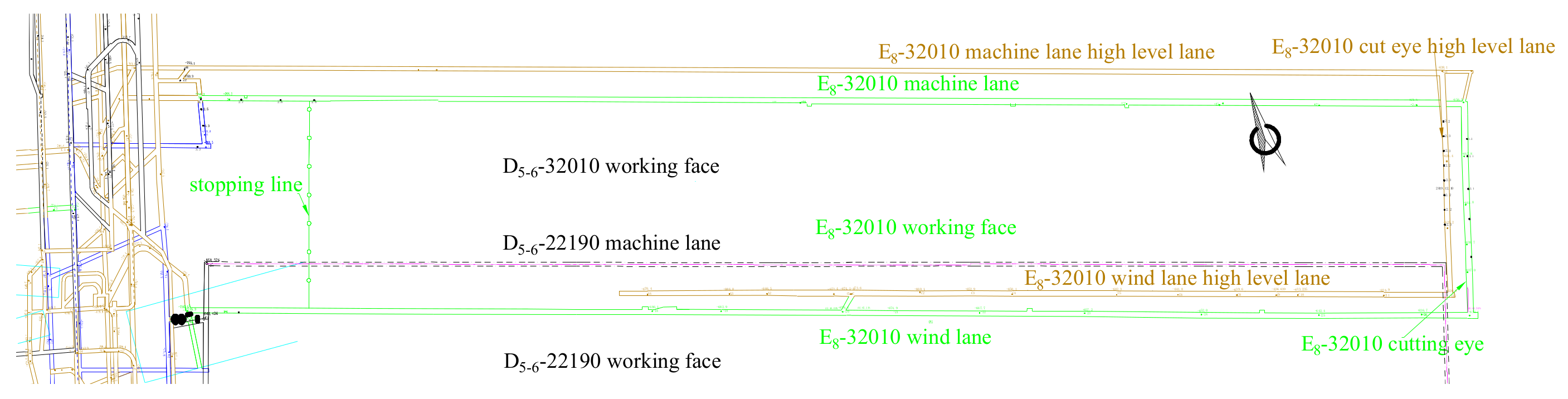
2. Geological Profile

The mine is located in the west–central zone of the Pingdingshan Coalfield, 8 km northwest of Pingdingshan City, under the jurisdiction of Xinhua District of Pingdingshan City. The E8-32010 working face is situated in the upper zone of the three−level E2 mining area located in the Six Mines of Ping Coal Company, with the protected coal pillar of the three−level E2 mining area in the west, part of the solid coal west of the boundary between the First and Sixth Mines in the east, the mined back E8-22310 mining air space in the shallow zone, and the unmined solid rock in the deep zone. The E8-32010 working face can be mined 2300 m along the strike, with a 220 m incline, a 160–260 m surface elevation, a −633–−768 m downhole elevation, and an 873–938 m burial depth. The main mining strata of the E8 coal are 2.2 m high, and the strike exhibits the long−wall backward all−collapsed coal mining method, where the average thickness of coal is 2.2 m, the inclined angle is 5.7°, and the distance from the upper D5-6 seam is 71 m. The working face is arranged according to the design of “one side and four lanes”, from top to bottom; the wind lane, high extraction lane of the wind lane, machine lane, and high extraction lane of the machine lane are arranged sequentially, among which the machine and wind lane are arranged along the E8 coal seam, and the high extraction lane of the machine lane and the high extraction lane of the wind lane are arranged along the rock layer of the upper coal seam; moreover, the working face is arranged in the lane arrangement (Figure 1), and the coal seam is in the form of columns (Figure 2).

3. Numerical Simulation Studies

3.1. Principles of Numerical Simulation
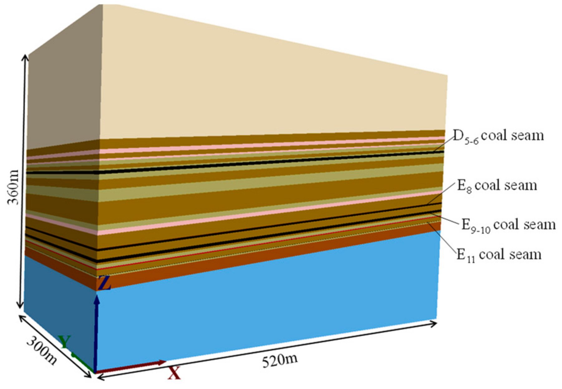
FLAC3D is a powerful numerical analysis and simulation software in the field of geotechnical engineering, which can realize the research on the stress distribution of surrounding rock, the movement of surrounding rock, and the evolution pertaining to the plastic zone of the coal rock body during the mining process that affects the working face of the underground coal mine under the condition of a three−dimensional model [8,26]. The running rules of FLAC3D numerical calculation are as follows:
(1) Equation of motion
The mass of the filling material and the force carried by each cell in FLAC3D are concentrated into a single mesh node, and the motion of the node can be calculated using the equation of motion (1):
ν i l / t = F i l ( t ) / m l
where F i l ( t ) denotes the unbalanced force component of node l in the i−direction at time t, which can be derived from the principle of virtual work; and ml denotes the total mass of node l, which is equal to the virtual mass in the static problem and the actual total mass in the non−dynamic problem.
The left−hand side of Equation (1) can be expressed in terms of center difference:
ν i l t + Δ t / 2 = ν i l t + Δ t / 2 + F i l t / m l Δ t
(2) Intrinsic equation
The relationship between strain rate and velocity can be described as Equation (3).
e i j = u i / x j + u j / x i
where eij denotes the component of strain rate, and ui denotes the component of velocity;
σ i j = M σ i j + e i j + k
where k denotes the time course parameter, and M denotes the expression for the principal constitutive equation.
(3) Strain, stress, and unbalanced forces
The strain increment of the mesh at a given time step can be calculated from the strain rate:
Δ e i j = 0.5 ν i , j + ν j , i Δ t
Based on the strain increment, the stress increment at each time step is obtained using the intrinsic equation and summed up to the total stress.
(4) Damping force
For the static problem, non−viscous damping can be added to Equation (5); thus, the system vibration is gradually reduced, and the system eventually attains equilibrium. Subsequently, Equation (5) can be rewritten as
ν i l = F i l t + f i l t / m l
The damping force can be expressed as
f i l t = a F i l t s i g n ν i l
where a denotes the damping coefficient. s i g n ν i l can be calculated from Equation (8):
s i g n = + 1 y > 0 1 y < 0 0 y = 0

3.2. Model Building

If we utilize the actual geology of the E8-32010 working face as the data basis, we can establish a 3D geological model (Figure 3), with a model length, width (coal seam strike), and height (coal seam inclination) of 520 m, 300 m, and 360 m, respectively, and with a 5.7° inclination angle of coal and rock seams. To enhance computational efficiency, the same parameters are utilized for the same rock formation, and the coal rock parameters (Table 1) are utilized in the numerical simulation.
To simplify the calculation model, the coal rocks at the top and bottom of the model, which are far away from the mining layer, are combined into the same rock layer. To weaken the influence of the model boundary effect on the calculation results, the model’s top and bottom boundaries were set at a vertical distance of more than 100 m from the coal seams of D5-6 and E11, the strike boundary (Y direction) was 100 m away from the excavation area, and the inclined direction (X direction) was 120 m away from the excavation area.

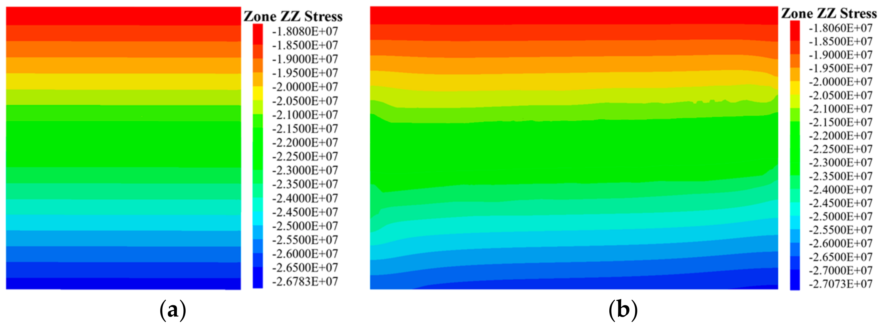
3.3. Initial Geostress Equilibrium

The simulation material is modeled using a Moore–Cullen model, and the coal rock parameters are depicted in Table 1. The model surface is divided into 6 surfaces: east, west, south, north, top, and bottom. The model boundary is controlled by acceleration, and the acceleration of five surfaces, namely east, west, south, north, and bottom, is assigned as 0 (i.e., the east, west, south, north, and bottom surfaces are fixed and immovable). The model’s top face, herein depicted in Figure 3, contributes to the vertically downward overlying coal–rock seam protolithic stress, which is calculated using Equation (9).
σ = γ H
where σ denotes raw rock stresses in the overlying rock layers, MPa; γ denotes the average volumetric weight of the overlying coal seam, herein set at 25.0 kN/m3; and H denotes the average thickness of the overlying coal seam, herein set at 720 m.
σ = γ H = 25.0 × 720 × 10 3 = 18.0 MPa
This study initialized the ground stress field to obtain the 3D ground stress field in the study area of the Six Mines of Pingmei Coal Company and obtained the strike and tendency stress distributions by slicing the model (Figure 4).
From Figure 4a,b, the initial geopathic stress of the coal beds in the model is decreasing (the depth of burial is increasing), and the original rock stress is gradually increasing, which is consistent with the law of geopathic stress distribution. Comparing Figure 4a,b, it can be observed that, at the same burial depth, the change in stress value in the direction of strike (Y−direction) is small, and the direction of strike is less affected by the model boundary; the change in stress value in the direction of inclination (X−direction) is large, and the stress distribution at the model boundary is not uniform; and the maximum vertical stress of the model is 27.07 MPa.

4. Coal Body Stress Distribution

During the upstream mining process, the mining activities in the lower seams lead to significant changes in the gas storage environment of the overlying seams and in the physical properties of the coal body [9,27]. The basis of all the aforementioned changes is stress change, which is the precondition for other factors to change. Therefore, analyzing the stress evolution law of the overlying coal seam is a crucial basis for guiding the unloading gas extraction from the overlying coal seam. Meanwhile, the length of the working face inclination that affects the mining layer impacts the degree of change in the stress environment of the overlying coal seam [28]. The starting point of excavation is X = 120 m, and the tendency lengths of the working face pertaining to the mining layer are 120 m, 160 m, 200 m, 220 m, 240 m, and 280 m; thus, we analyze the influence of different tendency lengths on the stress evolution of the overlying coal seam.

4.1. Stress Distribution in Modeled Profiles

Under the influence of mining activities, the stress in the overlying coal rock layer on the working face is changed from triaxial compression to an unloading state, and the bearing stress of the coal body within a certain range is reduced. However, the total stress in the same plane for the whole three−dimensional geologic model cannot be reduced but is shifted to the surrounding coal rock; subsequently, the surrounding rock carries the pressure of the overlying rock layer in the mining space [29]. By simulating the working face of the E8 coal seam with tendency lengths of 120 m, 160 m, 200 m, 220 m, 240 m, and 280 m in the numerical model of excavation, the calculation of the mining stresses during the mining of the protective seams was performed, and slices were subsequently taken at the position of y = 150 to indicate the vertical stresses in the tendency profiles (Figure 5).
From Figure 5, when the tendency mining length of the E8 coal seam is 120 m, the pressure of the upper coal rock is released; however, the release degree and the release range are small, and the phenomenon of a large increase in stress value occurs on both sides of the mining area of the E8 coal seam. Moreover, the stress peak is 37.35 MPa. With the increasing tendency length, the affected area pertaining to the upper zone of the mining field in the vertical direction is gradually increasing, the degree of stress relief is gradually increasing, and the low−stress area is broadening. The coal body stress of the D5-6 coal seam keeps decreasing, the rate of stress increase in the shallow zone of the mining area is lower than that in the deep zone, and the degree and range of pressure relief are more than in the deep zone of the coal body, which indicates that the effect of pressure relief and the protective layer is more optimal in the shallow zone of the coal body. Meanwhile, the degree of stress concentration on both sides of the mining area of the E8 seam also increased gradually with the mining length, and the peak stress attained 40.96 MPa when the mining area’s tendency length was 280 m.

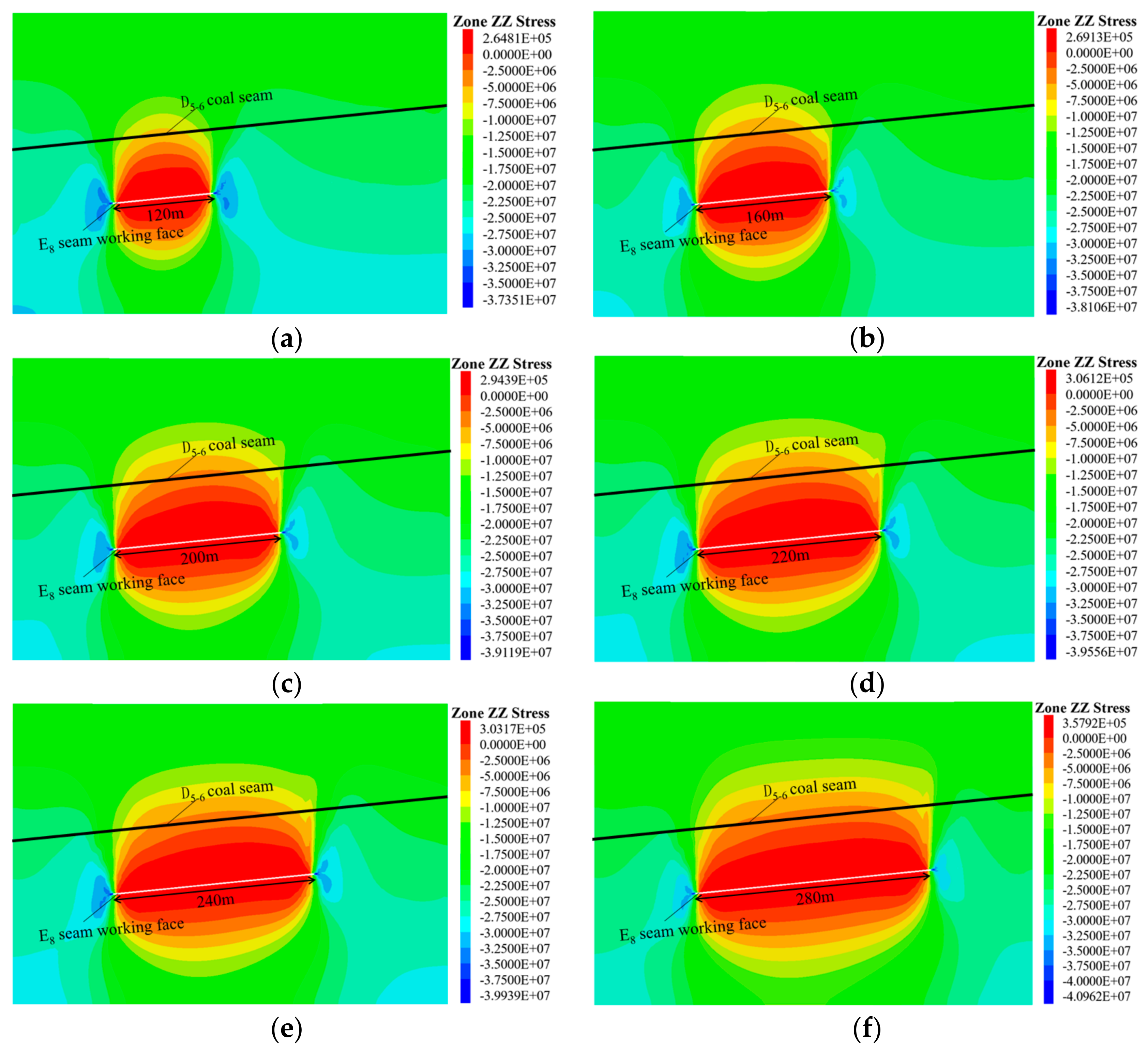
4.2. Stress Evolution in the Protected Layer

To indicate more intuitively the evolution law that affects the bearing stress of the D5-6 coal body as the protected seam in the case of different tendency lengths of E8 seam mining, the monitoring line is set up at the position of y = 150 within the D5-6 seam in the model, and a monitoring point is set up every 5 m. After the model calculation is completed, we extract the final vertical stresses of the excavation at 120 m, 160 m, 200 m, 220 m, and 240 m, respectively, and, after the model calculation, the final vertical stresses at the monitoring points were extracted at 120 m, 160 m, 200 m, 220 m, 240 m, and 280 m, respectively. A total of 105 vertical stress monitoring points are set up in the whole model. Due to the limitations of the model boundary effect and boundary conditions, the values of the monitoring points at 0 m and 520 m do not conform to the change rule. Therefore, we choose to remove the vertical stress monitoring data at 0 m and 520 m, and we depict the relationship between the valid data and the tendency length of the mining area (Figure 6).
From Figure 6, no matter how the tendency length changes, the stress of the D5-6 coal seam indicates that it first rises slowly and decreases rapidly to below the original stress value, falls to the lowest point, and subsequently rises rapidly, and that it exceeds the original stress to attain the highest point and decreases slowly, gradually approaching the original stress, which can be divided into stress increasing zone, stress decreasing zone, and stress increasing zone in regard to the proposed model. Moreover, when the model’s tendency length is sufficiently long, there will be one original rock stress zone on each side of the model, totaling five zones [30]. The deep coal body of the D5-6 seam, which exhibits higher original rock stress, manifests a higher stress increase than the shallow coal body, which has lower original rock stress, which reveals that most of the stress is transferred to the deep coal rock body after the protected layer is mined, and the shallow coal rock body bears only a small portion of the transferred stress.
With the increasing tendency length of the mining area pertaining to the E8 protection layer, the range of the pressure relief zone formed within the D5-6 coal seam gradually increased, and the degree of pressure relief gradually increased. Moreover, the minimum stress values within the coal seam continuously decreased, and the following values were recorded: 7.80 MPa, 6.42 MPa, 5.59 MPa, 5.42 MPa, 5.30 MPa, and 5.21 MPa. Compared with the original rock stress of more than 21.50 MPa, the minimum stress values in the unloading area of the D5-6 coal seam are 36.28%, 29.86%, 26.00%, 25.21%, 24.65%, and 24.23% of the original rock stress, values that are much lower than 40% of the original rock stress. The reduction in coal body stress is conducive to the expansion and deformation of the coal body of the protected seam, effectively increasing the volume of coal body pores and fissures, which increases the gas flow capacity of the D5-6 seam and is more conducive to eliminating the risk of protrusion and gas extraction [31].

5. Protected Layer Gas Extraction

The original gas pressure of the D5-6 coal seam in the study area of Six Mines of Pingmei Coal Company is 0.79–2.10 MPa, the original gas content is 5.84–6.64 m3/t, and the adsorption constants (a and b) are 18.97 m3/t and 0.56 MPa−1, respectively, belonging to the high−pressure and low adsorption coal seams. When mining the E8 coal seam, it is necessary to utilize the favorable pressure−unloading environment to conduct pressure−unloading gas extraction on the D5-6 coal seam, thus eliminating the danger of coal and gas protrusion in the D5-6 coal seam and realizing comprehensive anti−disruption and extraction up to the standard. Due to the difference in the relative positions of the D5-6 seam and the mining layer, the gas storage environment is not consistent, and the storage difference in the whole seam is large; therefore, the final location of the drilling hole affects the efficiency of unloading gas extraction. If we utilize the extraction efficiency as an indicator, exploring the relationship between the stress value of the unloaded coal body and the final location of the unloaded drilling hole is conducive to enhancing the scientific arrangement of the unloaded drilling hole and the extraction efficiency.

5.1. Arrangement of Extraction Drill Holes

Based on the underground lane arrangement and actual mining conditions of Six Mines of Pingmei Coal Company, a group of D coal seam pressure relief and extraction drill holes are arranged in the high−level lane of the E8-32010 machine lane, with the coal body’s stress value obtained in the previous chapter and the theoretical protection line for protective coal seam exploitation delineated with reference to the “Technical criterion of protective coal seam exploitation” [32].
In the high−level lane of the E8-32010 machine lane, regarding the construction of the E8-32010 working face before and after mining extraction drill holes, according to the previous on−site construction experience, normal drill holes with depths exceeding 120 m can immensely increase the offset of the drill holes; meanwhile, it is difficult to cause the drill holes to return. Therefore, the design of extraction boreholes should be less than 120 m long. A group includes three extraction drill holes; the diameter of the drill holes is 94 mm. One group is constructed every 30 m interval, and the interval between the drill holes within the group is 10 m. A total of three groups of pre−extraction drill holes before the back mining of the E8-32010 working face are constructed, and three groups of unpressurized extraction drill holes after the back mining of the E8-32010 working face are constructed as the investigation and experimental drill holes. Moreover, the drill holes are arranged with profiles (Figure 7), and the completion parameters of the drill holes are depicted as follows (Table 2).
The extraction drill holes are sealed by the “two blocking and one injection” bag-type pressurized grouting sealing method, and the depth of the sealing holes is as close as possible to the coal–rock junction. According to the simulation results, the vertical stresses of the No. 1, No. 2, and No. 3 holes before mining in the E8-32010 working face are 21.58 MPa, 21.56 MPa, and 21.53 MPa, respectively, and the vertical stresses after mining in the E8-32010 working face are 16.42 MPa, 10.74 MPa, and 6.72 MPa, respectively, all of which are smaller than the original stresses in the unpressurized area. The ratios of unpressurized value to original rock stress are 23.91%, 50.16%, and 68.79% respectively; the higher the unpressurized ratio, the more optimal the effect of coal body penetration and flow increase, and it is expected that the effect of unpressurized extraction in borehole No.3 will be higher than that in boreholes No. 1 and No. 2.

5.2. Analysis of Pre−Sampling Effects

In the area that is unaffected by the mining of the E8-32010 working face, pre−pumping drill holes were drilled through the D5-6 coal seam, and the extraction flow rate and concentration of the pre−pumping drill holes were converted into a pure amount of extracted gas. The holes were sealed immediately after the drilling work was completed, and, after the cement slurry solidified for 24 h, the gas extraction system was connected to perform high−negative−pressure pre−extraction. The pre−pumping pure quantity of gas was recorded continuously for 30 d before pumping, and the relationship between pre−pumping time and pure quantity of gas is depicted in Figure 8.
From Figure 8, the trend of the pure amount of gas extracted from the pre−pumping boreholes is consistent, and the pure amounts of gas extracted in a single day for 30 d of continuous pre−pumping of boreholes No. 1, No. 2, and No. 3 in the first and second groups are 1.69–3.37 m3/d, 2.13–4.53 m3/d, 3.12–5.96 m3/d, 1.68–3.38 m3/d, and 2.21–4.63 m3/d, and 3.35–6.05 m3/d, respectively. The average pure volumes of gas for 30 d of continuous extraction were 2.52 m3/d, 2.55 m3/d, 3.44 m3/d, 3.48 m3/d, 4.76 m3/d, and 4.83 m3/d, respectively, and the cumulative pure volumes of gas extracted were 75.73 m3, 76.46 m3, 103.08 m3, 104.54 m3, 142.80 m3, and 145.01 m3, respectively. The pure amount of gas extracted in a single day decreases with the continuous increase in extraction time. The cumulative attenuation of the No. 3 borehole is larger than that of No. 2, and the cumulative attenuation of No. 2 is larger than that of No. 1. This is because the inclination angle of the three drill holes is not the same as that of the coal seam, resulting in different lengths of the coal section of the drill holes. The longer the length of the coal section, the more coal bodies are exposed around the holes, the larger the volume of coal bodies that can be covered by the drill holes, and the larger the amount of gas extracted under the same geological conditions. The single−day and cumulative pure volume of gas extracted from different groups of drill holes with the same number do not differ considerably, thus indicating that the difficulty of extracting the original coal seams and the amount of gas reserves at different locations in the study area are the same. The average gas flow rates of the three groups of drill holes, No. 1, No. 2, and No. 3, for 30 days of continuous extraction were 2.54 m3/d, 3.46 m3/d, and 4.80 m3/d, respectively, and the cumulative pure volume values of the extracted gas were 152.19 m3, 207.62 m3, and 287.81 m3, respectively.

5.3. Pressure Relief Pumping Effect Analysis

The extraction efficiency of unpressurized extraction boreholes is related to the window period of unpressurized gas extraction, during which the extraction intensity is high and the flow rate is significant, potentially tens of times the pure amount of gas extracted from the pre−extraction boreholes [33]. The working face of the protected layer is pushed through the final hole position approximately 40 m into the unpressurized range [34]; to ensure that the experimental borehole extraction is located in the unpressurized range of the protected layer, we consider the time when the mining face is pushed through the final hole point 50 m as the starting point for data recording and we plot the relationship between the extraction time and the amount of pure gas (Figure 9).
Figure 9 indicates that the pure amount of extraction in the No. 1 hole is much smaller than that in the No. 2 hole, thus indicating that the extraction resistance of the No. 1 hole is larger than that of the No. 2 hole; moreover, it can be observed that the coal body around the final hole of the No. 2 hole exhibits a higher degree of unpressurization, and that the ability of gas flow is stronger. The extraction amount of the No. 3 hole is larger than that of the No. 1 and No. 2 holes, which indicates that the peripheral fissure is developed in the No. 3 final hole, and the gas inside the coal body of the surrounding areas is constantly flowing to the extraction holes under the joint action of gas pressure and negative pressure, which is the optimal extraction result. The gas in the surrounding coal body flows to the extraction hole continuously under the joint action of gas pressure and negative pressure; therefore, the extraction resistance is small, and the extraction effect is optimal. Meanwhile, there are major differences in the penetration enhancement effect in different areas; furthermore, the extraction efficiency is higher in the high penetration enhancement area, and the amount of drilling work is less. Although the change in the single−day gas extraction amount of the No. 1 drilling hole is not apparent in 30 d, it is apparently higher than that of pre−pumping drilling holes, which indicates that there is a certain penetration enhancement effect, and that there are sufficient gas reserves in the surrounding coals. The initially rising and subsequently falling trend of the No. 2 and No. 3 drilling holes in the 30 d extraction time indicates that, as the working face of the lower protection layer advances, the gas flow in the surrounding coals is reduced. As the working face of the lower protective layer advances, the penetration enhancement effect increases, and the penetration enhancement effect no longer increases after exceeding a certain range. Meanwhile, the gas reserve of the coal body around the final hole position decreases, and the unloaded gas flows to the final hole position from a farther position; therefore, the extraction resistance becomes larger, and the amount of extraction decreases.
The pure volume values of gas extracted from holes No. 1, No. 2, and No. 3 in the first and second groups were 83.88–124.58 m3/d, 238.43–324.47 m3/d, 503.41–806.43 m3/d, 76.76–132.71 m3/d, 240.56–334.86 m3/d, and 452.64–776.54 m3/d, respectively. The pure volume of extraction in all the holes is much larger than that in the pre−pumping holes. The average gas flow rates of holes 1, 2, and 3 for 30 d of continuous extraction are 104.21 m3/d, 288.22 m3/d, and 687.59 m3/d, respectively, and the cumulative pure volume of extracted gas values are 6252.48 m3, 17,292.99 m3, and 41,255.36 m3, respectively.

5.4. Analyzing the Effect of Depressurization and Penetration Enhancement

The borehole gas flow rate and the amount of gas extracted in the same period of time are effective indicators of the efficiency of borehole extraction, and the recorded gas extraction data were utilized to draw a comparative graph of gas extraction efficiency, as illustrated in Figure 10.
From Figure 10, the difference in bearing stress of the coal body near the final hole of the pre−pumping drill holes is not large, and, although there are differences in the average gas flow rate and total amount of pre−pumped gas, the difference is small compared with that of the unloading drill holes, mainly owing to the influence of the length of the drill holes in the coal seam. The average gas flow rate and cumulative amount of gas pumped in drill holes X1−1 and X2−1 are 39.54–42.63 and 19.77–21.31 times higher than pertaining to the average of pre−pumping hole No. 1, and the stress reduction before and after mining in the lower coal seam is 5.16 MPa. The average gas flow rate and cumulative tile extraction in drill holes X1−2 and X2−2 are, respectively, 83.23–83.35 and 41.62–41.68 times the average value of pre−pumped drill hole No. 2, and the stress reduction in drill hole No. 2 before and after mining the lower coal seam is 10.82 MPa, with a stress unloading rate of 50.91%. The stress unloading rate is 50.16%; the average gas flow rate and cumulative gas extraction of the X1−3 and X2−3 boreholes are 137.38–149.32 times and 68.68–74.66 times the average value of the No. 3 pre−pumping borehole, respectively; furthermore, the stress of the No. 3 borehole before and after mining in the lower coal seam is reduced by 14.81 MPa, and the stress unloading rate is 68.79%. The aforementioned observation indicates that, the greater the stress reduction in the coal body near the final hole position, the greater the unloading rate, and the more apparent the effect of coal body penetration enhancement. Moreover, the final hole position of the drill hole should be in the high unloading area as much as possible when unloading pressure and extracting.
According to the field mining experience, when the residual gas content of the D5-6 coal seam is reduced to 3.00 m3/t, it can effectively guarantee the safe and efficient mining of the D5-6 coal seam. The amount of coal liberated from a single hole is calculated according to Equation (10). The results of the calculations are depicted in Table 3.
G = Q / ( W 0 W cy )
where G denotes liberated coal quantity, t; Q denotes gas extraction quantity, m3; W0 denotes original gas content, herein set at 6.64 m3/t; and Wcy denotes residual gas content, herein set at 3.00 m3/t
From Table 3, it can be concluded that, the smaller the vertical stress at the final hole location of the extraction drill hole, the larger the amount of coal liberated from a single hole, while the ratio of the amount of coal liberated from unloading pumping and pre−pumping is also increasing.

6. Conclusions

(i)
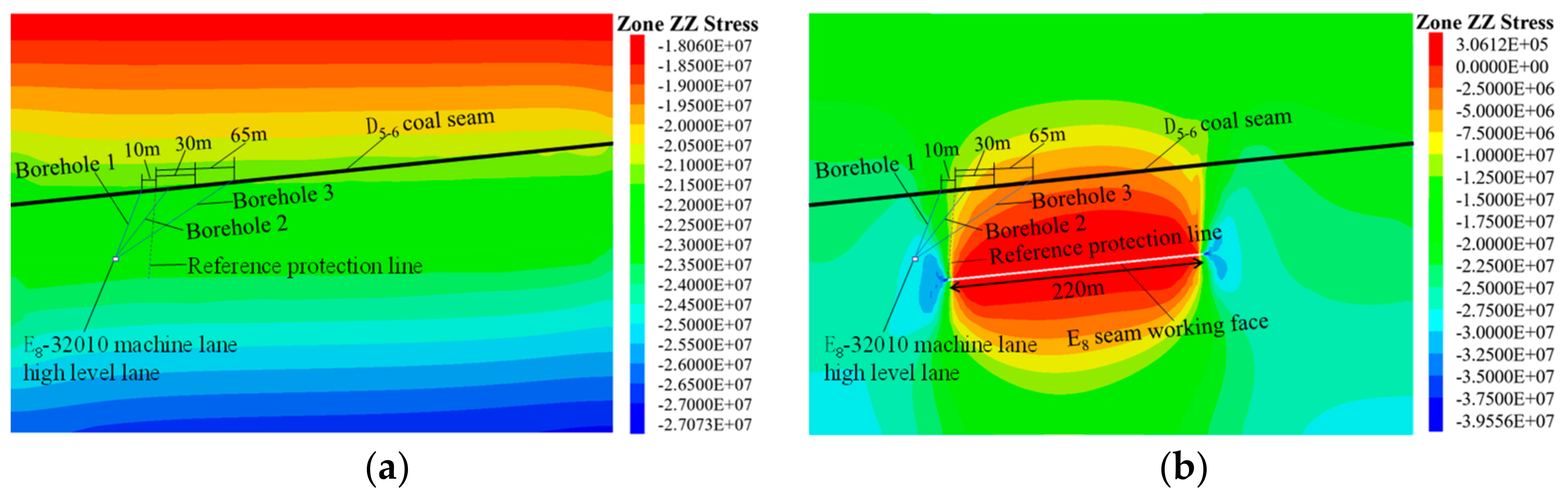
When mining the E8 coal seam, with the increase in tendency length, the unloading degree and unloading range of the protected layer are increasing, the stress increase in the deep D5-6 coal seam is larger than that of the shallow D5-6 coal seam, and the tendency direction can be divided into stress elevation area, unloading area, and stress elevation area from the shallow zone to the deep zone; moreover, the minimum stresses are all less than 40% of the original stresses.
(ii)
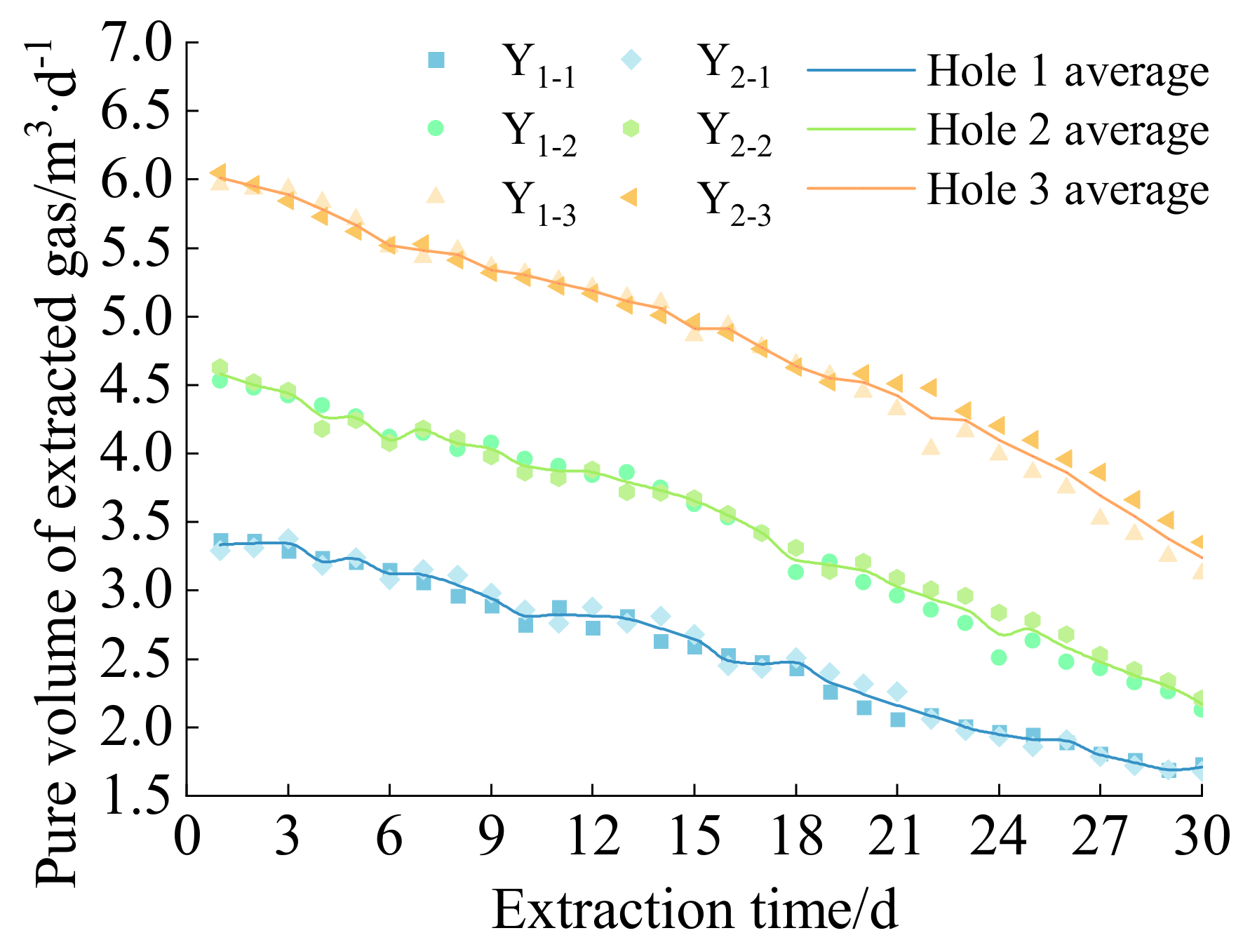
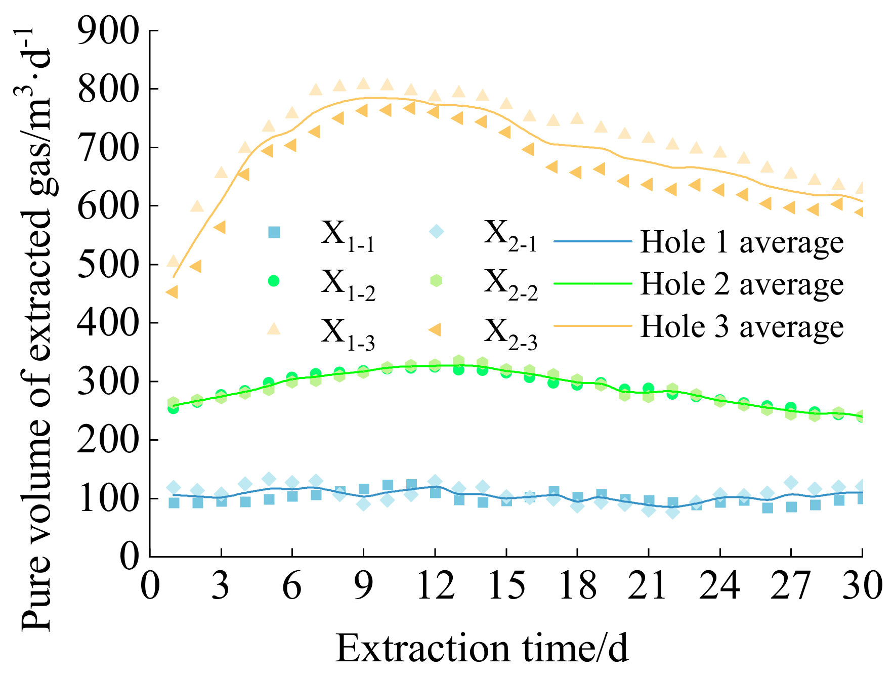
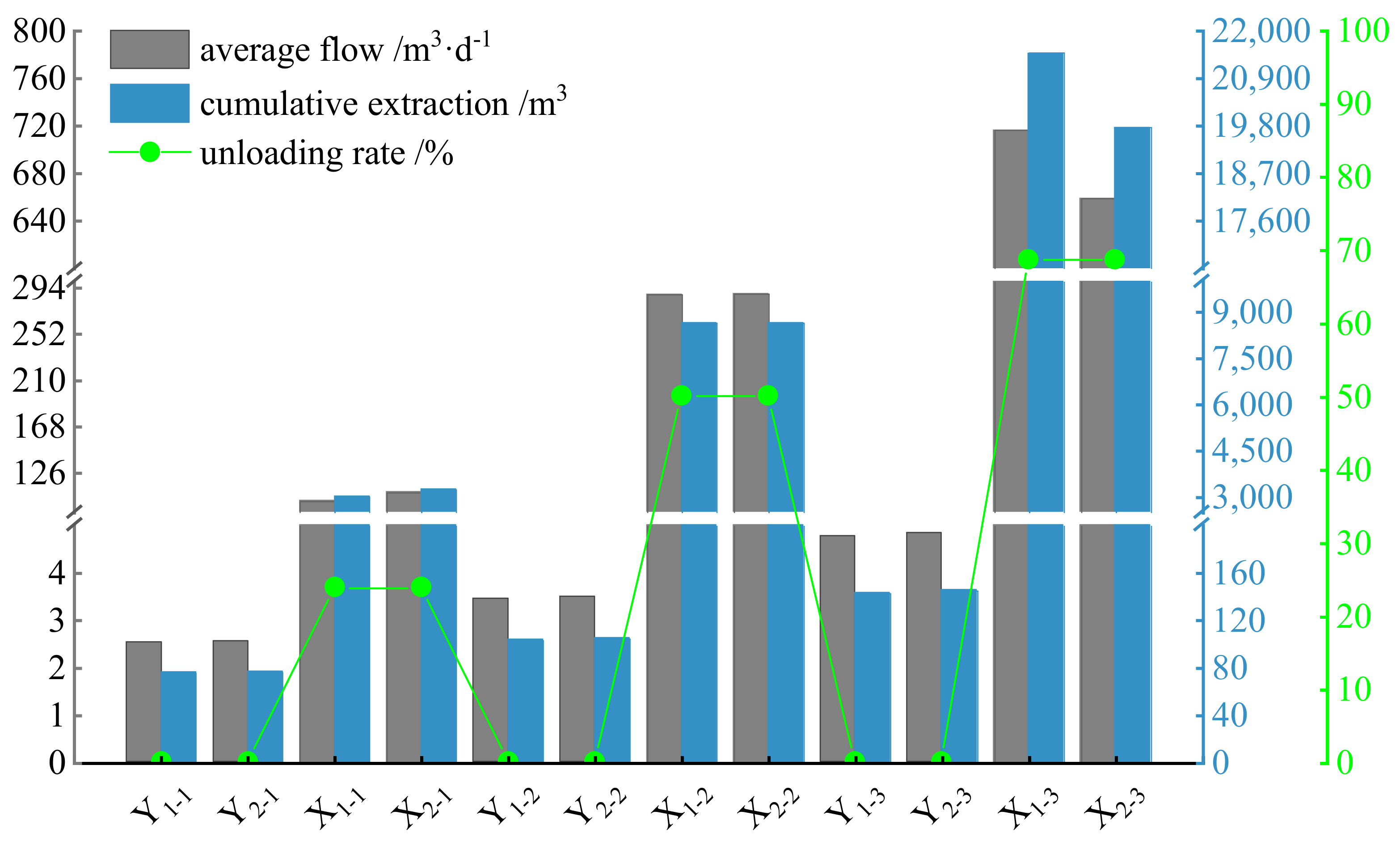
After excavation, the vertical stresses at the final hole locations of the No. 1, No. 2, and No. 3 drill holes were 16.42 MPa, 10.74 MPa, and 6.72 MPa, respectively, and the pure amount of gas extracted by unloading increased significantly, whereas, the higher the unloading rate, the greater the increase in the amount of extraction, and the unloaded drill holes extracted 19.77–21.31 times, 41.62–41.68 times, and 68.68–74.66 times, respectively, the pure amount of gas extracted by the corresponding pre−pumping drill holes. Moreover, the lower the vertical stress at the final hole location, the higher the gas extraction efficiency.
(iii)
The amount of coal liberated by the No. 3 unpressurized extraction borehole for 30 d continuously is 5430.58–5903.31 t, which is 138.43–148.18 times as much as that of the No. 3 pre−pressurized extraction borehole, and 6.09–7.14 and 2.28–2.49 times as much as that of the No. 1 and No. 2 unpressurized extraction boreholes, respectively. The lower the vertical stress at the location of the final borehole is, the higher the protection efficiency of the boreholes.
This study proposes that, when adopting protected seam mining as the measure of the releasing map in the area of a prominent coal seam, the design and construction of pressure relief drilling holes should fully consider the stress environment at the location of the final hole, which is not only conducive to eliminating the risk of coal and gas protrusion in the protected seam but can also optimize the amount of drilling work and the construction cost. This not only eliminates the risk of coal and gas protrusion in the protected seam but also reduces the amount of drilling work and construction cost. The basic theory of decompression mining in protected seam mining is further enhanced to provide a scientific rationale for designing and constructing decompression gas extraction drill holes.

Author Contributions

Writing—original draft preparation, J.X.; writing—review and editing, X.C.; methodology, S.L. and Z.C.; data curation, J.X. and R.B. All authors have read and agreed to the published version of the manuscript.

Funding

The research was supported by the National Natural Science Foundation of China (52174181,52204212) and the Supported by S&T Program of Hebei (22375401D).

Institutional Review Board Statement

Not applicable.

Informed Consent Statement

Not applicable.

Data Availability Statement

The data presented in this study are available on request from the authors.

Conflicts of Interest

The authors declare no conflict of interest.

References

  1. Yuan, L. Strategic thinking of simultaneous exploitation of coal and gas in deep mining. China Coal Soc. 2016, 41, 1–6. [Google Scholar]
  2. Xie, H.; Ju, Y.; Ren, S.; Gao, F.; Liu, J.; Zhu, Y. Theoretical and technological exploration of deep in situfluidized coal mining. Front. Energy. 2019, 13, 603–611. [Google Scholar] [CrossRef]
  3. Zhou, A.; Wang, K.; Fan, L.; Kiryaeva, T. Gas-solid coupling laws for deep high-gas coal seams. Int. J. Min. Sci. Technol. 2017, 27, 675–679. [Google Scholar] [CrossRef]
  4. Xie, H. Research review of the state key research development program of China:Deep rock mechanics and min-ing theory. China Coal Soc. 2019, 44, 1283–1305. [Google Scholar]
  5. Wang, E.; Zhang, G.; Zhang, C.; Li, Z. Research progress and prospect on theory andtechnology for coal and gas outburst control and protection in China. China Coal Soc. 2022, 47, 297–322. [Google Scholar]
  6. Zhang, C.; Tu, S.; Chen, M.; Zhang, L. Pressure-relief and methane production performance of pressure relief gas extraction technology in the longwall mining. J. Geophys. 2017, 14, 77–89. [Google Scholar] [CrossRef]
  7. Peng, X.; Qi, L.; Wang, Z.; Zhou, X.; Hua, C. Study on overburden movement deformationand roof breakage law of under-protective steeply inclined coal seam mining. Sustainability 2022, 14, 10068. [Google Scholar] [CrossRef]
  8. Tu, Q.; Cheng, Y. Stress evolution and coal seam deformation through the mining of a remote upper protective laye. Energy Sources Part. A. 2019, 41, 338–348. [Google Scholar]
  9. Cheng, X.; Zhao, G.; Li, Y.; Meng, X.; Tu, Q.; Huang, S.; Qin, Z. Mining-induced pressure-relief mechanism of coal-rock mass for different protective layer mining modes. Adv. Mater. Sci. Eng. 2021, 2021, 3598541. [Google Scholar] [CrossRef]
  10. Cheng, X.; Zhao, G.; Li, Y.; Meng, X.; Tu, Q. Key technologies and engineering practices for soft-rock protective seam mining. Int. J. Min. Sci. Technol. 2020, 30, 889–899. [Google Scholar] [CrossRef]
  11. Wang, L.; Lu, Z.; Chen, D.; Liu, Q.; Chu, P.; Shu, L.; Ullah, B.; Wen, Z. Safe strategy for coal and gas outburst prevention in deep-and-thick coal seams using a soft rock protective layer mining. Saf. Sci. 2020, 129, 104800. [Google Scholar] [CrossRef]
  12. Zhang, C.; Zhang, L.; Li, M.; Wang, C. A gas seepage modeling study for mitigating gas accumulation risk in upper protective coal seam mining process. Geofluids 2018, 2018, 8127207. [Google Scholar] [CrossRef]
  13. Li, W.; Cheng, Y.; Guo, P.; An, F.; Chen, M. The evolution of permeability and gas composition during remote protective longwall mining and stress-relief gas drainage: A case study of the underground Haishiwan Coal Mine. Geosci. J. 2014, 18, 427–437. [Google Scholar] [CrossRef]
  14. Cheng, H.; Dong, Y.; Li, X.; Chen, H. The dynamic evolution analysis of gas seepage field during the mining process of protective layer. Therm. Sci. 2019, 23 Pt. 3, 1371–1378. [Google Scholar] [CrossRef]
  15. Liu, H.; Cheng, Y. The elimination of coal and gas outburst disasters by long distance lower protective seam mining combined with stress-relief gas extraction in the Huaibei coal mine area. J. Nat. Gas. Sci. Eng. 2015, 27, 346–353. [Google Scholar] [CrossRef]
  16. Cao, Z.; He, X.; Wang, E.; Kong, B. Protection scope and gas extraction of the low-protective layer in a thin coal seam: Lessons from the DaHe coalfield, China. Geosci. J. 2018, 22, 487–499. [Google Scholar] [CrossRef]
  17. Niu, X.; Shi, B.; Zhang, Z.; Zhang, Y. Stress distribution and gas concentration evolution during protective coal seam mining. Adv. Civ. Eng. 2021, 2021, 6644142. [Google Scholar] [CrossRef]
  18. He, X.; Yang, K.; Han, P.; Liu, W.; Zhang, Z.; Wu, H. Permeability enhancement and gas drainage effect in deep high gassy coal seams via long-distance pressure relief mining: A case study. Adv. Civ. Eng. 2021, 2021, 6637052. [Google Scholar] [CrossRef]
  19. Wang, L.; Chen, X.; Wang, Z.; Xu, S.; Xu, Q. Extending the protection range in protective seam mining under the influence of gas drainage. J. South. Afr. Inst. Min. Metall. 2020, 120, 211–220. [Google Scholar] [CrossRef]
  20. Fan, Z.; Fan, G.; Zhang, D. Representation of mining permeability and borehole layout optimization for efficient methane drainage. Energy Rep. 2021, 7, 3911–3921. [Google Scholar] [CrossRef]
  21. Xie, G.; Li, X.; Cai, J.; Wang, S.; Feng, C. Evolution of fissures and pressure discharge of gas caused by mining of the upper protective layer of a coal seam. Sci. Rep. 2023, 13, 2561. [Google Scholar] [CrossRef]
  22. Dang, J.; Tu, M.; Zhang, X.; Bu, Q. Analysis of the influence of upper protective layer mining on the effect of pressure relief and protection of coal and rock masses between the lower overburden layers. Adv. Civ. Eng. 2021, 2021, 8682156. [Google Scholar] [CrossRef]
  23. Fang, S.; Liang, B.; Sun, W.; Qin, M.; Shi, Z.; Hao, J. Study on stress evolution law of upper coal seam in long-distance advance mining of lower coal seam. Energy Sci. Eng. 2023, 11, 1753–1769. [Google Scholar] [CrossRef]
  24. Wang, F.; Zhang, C.; Liang, N. Gas permeability evolution mechanism and comprehensive gas drainage technology for thin coal seam mining. Energies 2017, 10, 1382. [Google Scholar] [CrossRef]
  25. Xue, J.; Xiao, J.; Du, X.; Shi, Y. Current situation and development trend of pressure-relief gas extraction in theprotective layer mining in coal mines in China. Coal Geol. Explor. 2023, 51, 50–61. [Google Scholar]
  26. Yuan, Z.; Jiang, Z.; Li, S.; Zhao, J.; Huang, F. Numerical Assessment on Unloading Disturbance and Gas Extraction in Remote Distance Protective Layer Mining. Geofluids 2022, 2022, 3679384. [Google Scholar] [CrossRef]
  27. He, A.; Fu, H.; Huo, B.; Fan, C. Permeability enhancement of coal seam by lower protective layer mining for gas outburst prevention. Shock. Vib. 2020, 2020, 8878873. [Google Scholar] [CrossRef]
  28. Zhang, H.; Wen, Z.; Yao, B.; Chen, X. Numerical simulation on stress evolution and deformation of overlying coal seam in lower protective layer mining. Alex. Eng. J. 2020, 59, 3623–3633. [Google Scholar] [CrossRef]
  29. Hou, P.; Xue, Y.; Gao, F.; Wang, S.; Jiao, X.; Zhu, C. Numerical evaluation on stress and permeability evolution of overlying coal seams for gas drainage and gas disaster elimination in protective layer mining. Mining Metall. Explor. 2022, 39, 1027–1043. [Google Scholar] [CrossRef]
  30. Wang, L.; Wang, Z.; Xu, S.; Zhou, W.; Wu, J. A field investigation of the deformation of protected coal and its application for CBM extraction in the Qinglong coalmine in China. J. Nat. Gas. Sci. Eng. 2015, 27, 367–373. [Google Scholar] [CrossRef]
  31. Yao, B.; Ma, Q.; Wei, J.; Ma, J.; Cai, D. Effect of protective coal seam mining and gas extraction on gas transport in a coal seam. Int. J. Min. Sci. Technol. 2016, 26, 637–643. [Google Scholar] [CrossRef]
  32. AQ 1050–2008; Technical Criterion of Protective Coal Seam Exploitation. Standards Press of China: Beijing, China, 2008.
  33. Xi, J.; Wang, Z.; Chen, D.; Chen, J. Study on time–space characteristics of gas drainage in advanced self-pressure-relief area of the stope. Energy Sci. Eng. 2023, 11, 1311–1324. [Google Scholar]
  34. Jiang, W.; Zhao, L.; Cheng, B. Variation characteristics of coal rock layer and gas extraction law of surface well under mining pressure relief. Arab. J. Geosci. 2021, 14, 298. [Google Scholar] [CrossRef]
Figure 1. Layout of the working face.
Sustainability 16 02133 g001
Figure 2. Histogram of coal seams.
Sustainability 16 02133 g002
Figure 3. Model diagram.
Sustainability 16 02133 g003
Figure 4. Initial geostress balance: (a) strike direction; (b) dip direction.
Sustainability 16 02133 g004
Figure 5. Stress distribution of different tendency lengths of the working face: (a) 120 m; (b) 160 m; (c) 200 m; (d) 220 m; (e) 240 m; and (f) 280 m.
Sustainability 16 02133 g005
Figure 6. Comparison of stress variation with initial stress at different inclination lengths in the mining area.
Sustainability 16 02133 g006
Figure 7. Profiles of extraction borehole arrangement: (a) pre-extraction borehole; (b) pressure relief extraction borehole.
Sustainability 16 02133 g007
Figure 8. Pure volume trend of pre−pumped gas over time.
Sustainability 16 02133 g008
Figure 9. Trends in the amount of pure gas extracted by depressurization over time.
Sustainability 16 02133 g009
Figure 10. Comparing gas extraction efficiency.
Sustainability 16 02133 g010
Table 1. Parameters of the modeled coal rock.
LithologyDensity
/kg.m−3
Bulk Modulus
/Pa
Shear Modulus
/Pa
Tensile
Strength/Pa
Cohesion
/Pa
Frictional Angle/°
Overlying rock25009.67 × 1097.64 × 1095.68 × 1065.71 × 10646
Sandy mudstone24806.41 × 1095.32 × 1091.23 × 1061.97 × 10635
Fine sandstones28508.42 × 1096.15 × 1092.73 × 1062.65 × 10640
Mudstone24505.74 × 1093.31 × 1091.02 × 1061.61 × 10632
D5-6 coal seam14301.46 × 1091.11 × 1090.64 × 1060.93 × 10628
Carbonaceous Mudstone24505.63 × 1094.98 × 1091.66 × 1061.78 × 10635
E8 coal seam14902.06 × 1091.46 × 1091.51 × 1061.08 × 10630
E9-10 coal seam14501.86 × 1091.35 × 1091.42 × 1060.99 × 10630
Siltstone25507.43 × 1096.24 × 1091.65 × 1062.17 × 10638
E11 coal seam14601.88 × 1091.40 × 1091.45 × 1061.02 × 10630
Medium sandstone26008.97 × 1097.15 × 1093.71 × 1063.65 × 10640
deep rock layer25009.67 × 1097.64 × 1095.68 × 1065.71 × 10646
Table 2. Borehole completion parameters.
Borehole NameBorehole PositionElevation Angle/°Borehole Length/mCoal Length/m
Y1−1G28 point is 8 m away6559.23.8
Y1−2G28 point is 18 m away4185.35.9
Y1−3G28 point is 28 m away32115.47.7
Y2−1G28 point is 38 m away6560.14.0
Y2−2G28 point is 48 m away4184.95.8
Y2−3G28 point is 58 m away32114.87.9
X1−1G30 point is 5 m away6559.33.9
X1−2G30 point is 15 m away4184.95.9
X1−3G30 point is 25 m away32115.28.0
X2−1G30 point is 35 m away6559.63.8
X2−2G30 point is 45 m away4185.75.7
X2−3G30 point is 55 m away32114.67.8
Table 3. Calculating the amount of coal liberated from a single hole.
Borehole NumberVertical Stress /MPaExtraction
Method
30 d Cumulative Extraction/m3Liberated Coal/tRatio of Liberated Coal VolumeRatio of Borehole 3 to Other Boreholes
1#21.58pre−extraction75.73–76.4620.80–21.0139.73–42.42261.02–281.04
16.42unloading pump3008.93–3243.55826.63–891.096.09–7.14
2#21.56pre−extraction103.08–104.5428.32–28.7282.77–83.82191.77–205.55
10.74unloading pump8640.26–8652.732373.70–2377.122.28–2.49
3#21.53pre−extraction142.80–145.0139.23–39.84138.43–148.18138.43–148.18
6.72unloading pump19,767.30–21,488.065430.58–5903.31
Disclaimer/Publisher’s Note: The statements, opinions and data contained in all publications are solely those of the individual author(s) and contributor(s) and not of MDPI and/or the editor(s). MDPI and/or the editor(s) disclaim responsibility for any injury to people or property resulting from any ideas, methods, instructions or products referred to in the content.

