Article

Analysis of Grid-Forming Inverter Controls for Grid-Connected and Islanded Microgrid Integration

1
Electrical & Computer Engineering Department, Texas Tech University, Lubbock, TX 79409, USA
2
College of Engineering, West Texas A & M University, Canyon, TX 79016, USA
3
National Wind Institute, Texas Tech University, Lubbock, TX 79409, USA
*
Author to whom correspondence should be addressed.
Sustainability 2024, 16(5), 2148; https://doi.org/10.3390/su16052148
Submission received: 21 December 2023 / Revised: 6 February 2024 / Accepted: 7 February 2024 / Published: 5 March 2024
(This article belongs to the Special Issue Reliability of Onshore and Offshore Wind Energy Generation Systems)

Abstract

:
Autonomous grid-forming (GFM) inverter testbeds with scalable platforms have attracted interest recently. In this study, a self-synchronized universal droop controller (SUDC) was adopted, tested, and scaled in a small network and a test feeder using a real-time simulation tool to operate microgrids without synchronous generators. We presented a novel GFM inverter control adoption to better understand the dynamic behavior of the inverters and their scalability, which can impact the distribution system (DS). This paper provides a steady-state and transient analysis of the GFM power inverter controller via simulation to better understand voltage and frequency stabilization and ensure that the critical electric loads are not affected during a prolonged power outage. The controllers of the GFM inverter are simulated in HYPERSIM to examine voltage and frequency fluctuations. This analysis includes assessing the black start capability for photovoltaic microgrids, both grid-connected and islanded, during transient fault conditions. The high photovoltaic PV penetration levels open exciting opportunities and challenges for the DS. The GFM inverter control demonstrated appropriate response times for synchronization, connection, and disconnection to the grid. The DS has become more resilient and independent of fossil fuels by increasing the penetration of inverter-based distributed energy resources (DERs).

1. Introduction

Electrical grids have achieved a significant degree of maturity throughout history. Traditionally, these systems involve synchronous generators that rely on fossil resources to maintain mechanical inertia and are helpful as a backup to respond to unforeseen events or even natural disasters [1]. Over the past five years, the path to decarbonization has gained strength across countries such as Canada, the United States [2,3], Turkmenistan, Puerto Rico, and some countries in Latin America, which have signed agreements to control carbon emissions [1,4]. Eliminating petroleum, natural gas, and coal is challenging because many structures use these fossil fuels and changing them will require effort. Technological challenges and emerging solutions strongly influence the transition from fossil fuels to 100% renewable energy in 2050 into electrical grids [1,5,6]. The global energy goal is to achieve a more resilient and environmentally friendly power system. The next generation [7] of smart grids depends on the decision to produce 100% carbon-free electricity [8]. Therefore, high penetration [9] of renewable energy into the grid is required to modernize the electrical grid [10]. This leads to challenges in adopting emerging technologies that allow for the replacement of the conventional synchronous generator with a grid-forming (GFM) control that mimics synchronous machines because of its ability to form a voltage phasor [11,12]. Today’s grid has been characterized by grid-following (GFL) inverters, whose synchronization mechanism is a phase-locked loop (PLL) [13,14,15]. One drawback to using a PLL is that its control is limited and non-democratic [7,16,17].
However, the high penetration of renewable energy sources (RESs) operating as part of large interconnected systems can impact the security of the supply of electrical power systems. This is because there is no rule for determining a safe penetration level. However, when voltage and frequency stability are obtained, it is possible to validate whether the system accepts such a level of controller penetration. If the node voltage of the network is lower than 0.95 p.u. or higher than 1.05 p.u. and the situation stays for longer than 10 s, then the system can be defined as unstable [7]. If the frequency variation is outside the predetermined range, such as 59.7–60.3 Hz, the system is also considered unstable [18]. The high penetration of RES in large interconnected systems presents challenges such as intermittency and variability of RES generation, grid integration and stability concerns, grid congestion and curtailment issues, additional balancing and ancillary service requirements, increased complexity in system operation, integration costs and infrastructure upgrades, localized environmental impacts, supply–demand imbalance during low RES generation, and the need for advanced grid management techniques; mitigation strategies include forecasting, energy storage, and demand-side participation.
GFM power inverter control requirements include but are not limited to voltage and frequency ride-through, real power control, reactive power control, dynamic real power support under abnormal frequency conditions, dynamic voltage support under abnormal voltage conditions, power quality, negative sequence current injection, and system protection [19]. The capability and performance standards are universally necessary to connect inverter-based resources plants to transmission and sub-transmission networks and their interoperability. They will be adequate for most installations [20].
According to modeling tests conducted at the transmission level, GFM power inverters can enhance the voltage and frequency stability of bulk power networks [21], according to modeling tests carried out at the transmission level [22]. In [23], the authors built a model and investigated the controller stability, synchronization dynamics, and behavior. It is demonstrated that the system voltages and frequencies display nonlinear droop-like behavior and are controlled in a decentralized manner [23,24]. Small signal models were developed for both systems of connected GFM inverters, and a single inverter connected to an infinite voltage bus [23,24,25]. This study utilized small-signal models to simplify the analysis of complicated inverter systems. With the Andronov–Hopf oscillator control, the synchronization and small-signal stability analysis for the coupled GFM inverters were analyzed. Analysis and findings demonstrate the decentralized voltage and frequency regulation of GFM power inverters [7].
GFM power inverter controller technology is attracting interest from the research community as a potential robust controller [26]. However, creating an accurate description of a GFM inverter is challenging because these traits are still being developed in tandem with the shifting demands of power systems worldwide. In [19], the authors defined the GFM capability required for safe grid operation with an extensive penetration of GFM inverters [22].
The purpose of the research in [27] was to enlighten the academic community, business community, and government research organizations by thoroughly examining the challenges and opportunities in integrating inverter-based resources and providing advice on viable technology approaches. The roadmap described in [27] first presents formal definitions for the themes related to grid stability and then compares GFM inverters and conventional GFL inverter control techniques [25]. The final section of this roadmap provides a multiyear outlook on the progressive field validation of the GFM inverters, as shown in Figure 1 [27]. Each level of the triangle represents a specific goal to be met in a fixed period of years.
In [28], the author presented inverter-based resources and GFM inverter controllers, which regulate terminal voltage, enable island operation, maintain grid stability, and help with black start capability. A virtual oscillator controller (VOC) is a time-domain control technique that instructs the inverter to simulate the dynamics of a nonlinear electrical oscillator using a digital controller [29]. It can synchronize multiple units, has droop characteristics, and does not require a power filter. It was found that GFL inverters perform effectively when coupled with VOC inverters. The coupled inverter systems may become unstable when the penetration level increases. The system parameters determine the “tipping point” at which the system becomes unstable. A GFM inverter can increase the stability of the system. The utilities and grid operators must act quickly to incorporate renewable and variable-generating resources into the system while keeping the lights on and prices manageable as the energy sector undergoes a rapid transformation. Important planning, investment, and operational choices are influenced by high-fidelity modeling and extremely difficult simulations of the increasingly complex interdependencies and dynamics of the evolving power grid of the power system [22]. Emerging grid technologies and the data streams they provide can be used by utilities to balance energy system use.
This paper significantly contributes to the field by addressing the lack of clarity in previous discussions. It focuses on the vital role of grid modeling in meeting rising consumer expectations and adapting to the development of distributed energy resources (DERs). In this context, utilities and grid operators gain actionable insights to expand and achieve value and growth [30]. The importance of maintaining black start-competent generators in power utilities to activate the transmission system during blackouts is emphasized.
The key contributions of the paper can be summarized as follows:
Comprehensive Control Strategy Analysis:
This paper offers an extensive analysis of control strategies for scalable GFM inverters. This includes a detailed examination of droop control, virtual impedance control, and model predictive control.
Performance Comparative Analysis:
The authors conduct a comparative analysis of GFM inverter controller strategies, assessing their performance in both grid-connected and islanded modes of operation.
Introduction of Scalable Hybrid Control Strategy:
A novel contribution is the proposal of a scalable hybrid control strategy. This strategy combines the advantages of droop control and virtual impedance control, demonstrating improved performance in both grid-connected and islanded modes.
Investigation of Impactful Parameters:
This paper delves into the impact of various parameters, such as load variations and network disturbances, on the performance of different control strategies.
Furthermore, this paper extends its applicability beyond a small network with six inverters. The framework, analysis, and methodology introduced can be scaled to other feeders, showcasing a versatile control model. This research paper introduces GFM controller technology, operating in self-synchronization or droop mode. This technology facilitates scalable studies without the need for dedicated synchronization devices. The scalability of GFM inverters in both small-scale and large-scale networks is explored, providing insights into their applicability across diverse system configurations. This research paper also contributes to the decarbonization of the electrical grid by leveraging the self-synchronization capability of GFM power inverter control.
This study represents a significant advancement in the field of GFM inverter control strategies, distinguishing itself from previous research in several key aspects. Unlike prior studies focused on small-signal stability analysis, grid strengths, and control parameters, this work takes a pioneering approach by filling existing gaps in the literature.
The cornerstone of the contribution lies in the comprehensive control strategy analysis conducted by the researchers. This analysis provides a thorough exploration of control strategies tailored specifically for scalable GFM inverters. The researchers delve into the intricacies of various control techniques, such as droop control, virtual impedance control, and model predictive control. What sets this study apart is the unwavering emphasis on scalability, shedding light on the adaptability and performance of these controllers across diverse operational conditions.
Moreover, this research transcends the realm of theoretical discussions. This study introduces a performance comparative analysis, a novel aspect that assesses the practical performance of GFM inverter control strategies. This assessment spans both grid-connected and islanded modes of operation and notably includes an examination of black start capabilities in scenarios involving multiple controllers.
In summary, this work not only addresses the limitations found in previous studies but also takes a leap forward by providing a comprehensive analysis of scalable GFM inverter control strategies. The inclusion of a comparative performance evaluation in real-world scenarios adds a practical dimension, contributing significantly to a more nuanced understanding of these control methods. The researchers believe their work significantly advances the current state of knowledge in this domain.
The controllers mimic virtual synchronous machines, facilitating the integration of renewable energy sources. Additionally, this paper demonstrates the scalability of GFM power inverter control through real-time simulations, focusing on transient response and ensuring acceptable voltage and frequency variations in distribution systems. Section 2 provides an overview of the support framework. In Section 3, we unveil the innovative GFM inverter control technology proposed in this paper. Section 4 presents two case studies and a configuration for droop coefficients and parameters of the adopted GFM inverter control. Section 5 demonstrates the impact of the GFM power inverter, which includes, but is not limited to, voltage and frequency ride-through, real power control, reactive power control, dynamic real power support under abnormal frequency conditions, dynamic voltage support under abnormal voltage conditions, power quality [19,20,31].
The focus of this study is to evaluate the performance of the GFM power inverter control in grid-connected field modes. Simulations are presented to evaluate the proposed GFM power inverter control in different networks. The conclusions regarding the GFM inverter control as a key asset of grid modernization were drawn appropriately based on the data from simulations obtained in a real-time simulator. This study was benchmarked with similar studies performed in [18,32,33,34].

2. Overview of the Support Framework

Today’s grids extensively utilize inverters to establish a crucial interface between the electrical grid and RES, encompassing photovoltaic (PV) arrays, wind turbines, electric vehicles, and batteries [35]. The integration of advanced power electronic technology plays a pivotal role in safeguarding the network against various challenges, including voltage instability, fluctuation, poor power factor, harmonics, DC bias, AC bus voltage magnitudes variation, and transient stability issues.
During grid blackouts, conventional inverters adopt a “GFL” approach by shutting off power to any RES until a safe restart is possible. The emergence of GFM inverters represents a notable advancement, offering an independent means to restore the grid [36]. This innovative technology proves practical in effectively managing disturbances and finds application in interconnected systems (IS) comprising node regions with nonlinear loads, specifically designed to address associated challenges.
The GFM power inverter serves as a cost-effective device facilitating the interface between larger grids and microgrids [3]. It operates by converting DC power to AC at the required frequency and voltage through an always-on universal droop control mechanism, eliminating the need for external communication or PLL systems [36,37,38,39,40]. However, the effectiveness of this device hinges on the implementation of a robust control strategy capable of addressing disturbances such as grid voltage and frequency issues, as well as blackouts.
This paper significantly contributes to the discourse on grid modernization, particularly emphasizing the critical role of GFM inverters. The contributions can be categorized into three key areas:
Differential Factors Between GFL and GFM Inverters:
This paper introduces distinctive factors between GFL inverters and GFM inverters. GFM inverters, operating autonomously, have the capability to create networks and establish necessary conditions for self-synchronization. This includes an “always-on” function to prevent trip-offs and blackouts. Even during grid faults, there is fault-tolerant analysis and resynchronization/reconnection with the grid while ensuring the supply to local loads. Additionally, GFM inverters perform black start functions without the aid of a generator and operate without the need for communication networks or a PLL [41,42]. The interaction with the grid is characterized by friendliness and adaptability. In contrast, traditional GFL inverters typically act as current sources in a network [43].
The critical analysis emphasizes the transformative nature of GFM inverters in providing a more resilient approach to grid restoration, highlighting their distinct advantages over traditional GFL inverters. The incorporation of GFM technology introduces a paradigm shift in grid management strategies, ensuring continuous operation even in challenging conditions.

2.1. GFM Inverter Control Characteristics

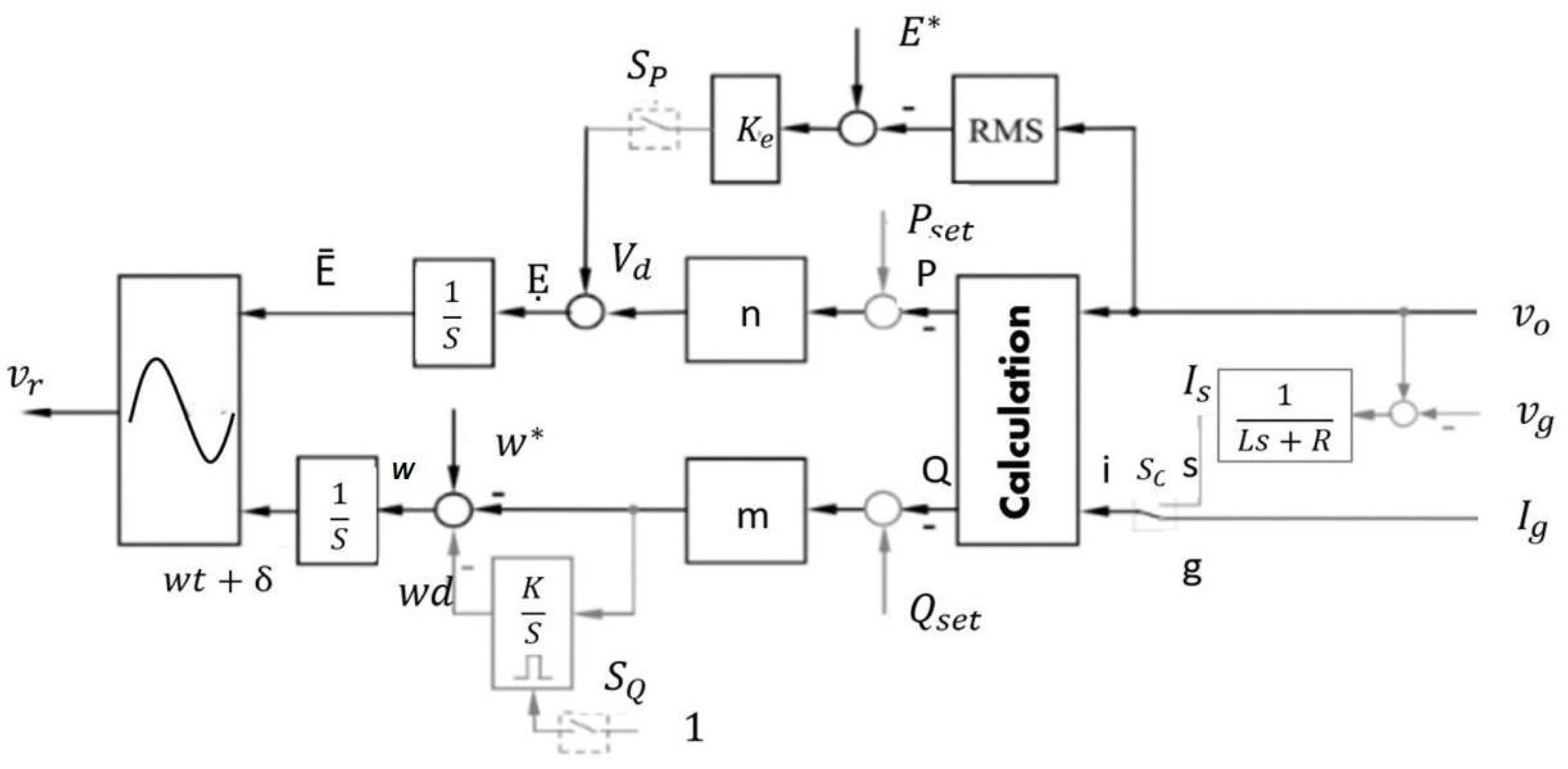
An SUDC can operate in droop mode and achieve synchronization by itself [32]. Blocks can be added to the original design of the UDC. The first block represents a virtual impedance, which is a fraction where the numerator is 1, and the denominator is a series between a virtual inductance and a resistor. It is located before the power calculation block [32]. The second block is an integrator that regulates Qset—Q to zero—which is controlled by a reset function. In contrast to the UDC, the SUDC contains switches. One of these switches enables or disables the addition of a specific term from the controller, known as SP. Another switch, SQ, enables or disables the reset function. The third switch, SC, sets two positions as g or s [32,44].

2.2. Microgrids in Operation in West Texas

Approximately 3.3 gigawatts are the current tiny fraction of U.S. electricity from microgrids. Because of its capability to keep the power during and after a natural disaster and integrate multiple renewable energy resources, its use and interest are growing each day around the world [45,46]. Many research institutes and university facilities have adopted microgrids [47] as part of their research strategies for the dynamic analysis of DERs.
The last preliminary monthly electric generator inventory report has estimated that approximately 54% of new energy capacity in 2023 will be powered by the sun [48]. Being the most utility-scale, renewable capacity added in a year, this capacity represents more than double the current record. A microgrid must meet specific technical requirements, such as operation in grid-connected and islanded modes. The U.S. electric grid currently has 66 balancing authorities and several interconnections; ERCOT is the interconnection in Texas [49]. A renewable energy scenario was found at the Reese Technology Center in West Texas, USA [50]. A microgrid [35] installed at the Global Laboratory for Energy Asset Management and Manufacturing (GLEAMM) that runs continuously could adopt the technology provided by the GFM power inverter control [51]. Previously, other studies with data collected from the Texas Mesonet Archive have been used based on the microgrid for solar irradiance prediction [52]. The next step for validating the GFM power inverter control on-site is to place it in the GLEAMM microgrid to evaluate its performance in a real scenario. The characteristics of GLEAMM microgrids can be found in [50].

3. Proposed GFM Inverter Control

Usually, a GFL inverter requires a dedicated synchronization method [32]. The difference between the grid voltage and inverter output voltage must be small to allow for current-limiting capability [53,54] when inverters are connected to the electrical grid. Therefore, a PLL is technically used to achieve this goal. Nonetheless, a PLL is highly nonlinear, which inevitably complicates the system [15,55]. If there are many PLLs in an electrical distribution system, these devices tend to compete. The problem associated with the conventional PLL is eliminated by replacing it. Now, the inverter can use self-synchronization mechanisms embedded into the UDC [32,44,56]; as a result, the inverter can mimic [57] a synchronous generator. Furthermore, another problem related to inverters that act as a current source is that the high penetration of GFL inverters can cause instability in the system. If an outage occurs, the GFM inverter waits for a signal from the generator.
The investigations recent works on GFM inverters frequency synchronization and restoration focus on the application of droop control and virtual impedance techniques. These techniques aim to ensure power sharing among GFM inverters and facilitate power flow within the system.
Droop Control:
The reference of the voltage control loop, denoted as v r e f , is provided by a decentralized control system consisting of the droop controller.
The amplitude and phase of the voltage reference are generated by the droop control based on the measured active and reactive powers.
Droop functions are expressed through equations, involving nominal frequency and voltage references, as well as droop coefficients for frequency ( m ) and voltage ( n ).
Droop Coefficient Selection:
Droop coefficients m and n are selected based on equations involving maximum frequency and voltage amplitude deviations ( Δ f and Δ V ) and rated active and reactive powers ( Δ P and Δ Q ).
The averaged power is calculated through a low-pass filter to attenuate high-frequency noises.
Virtual Impedance Loop:
A virtual impedance loop is introduced to the decentralized control to enhance current sharing between GFM inverters.
This loop fixes and normalizes the output impedance of GFM inverters, determining the power angle/amplitude relationship (inductive droop) without the need for additional physical inductors/resistors.
The virtual impedance loop includes equations defining virtual voltage compensation and output current in d q —reference frame, considering virtual resistance ( R v ) and inductance ( L v ) values.
Stability Analysis:
Closed-loop modeling and stability analysis of the virtual impedance loop have been studied in previous works, and these details are not addressed in the provided text.
The integration of droop control and virtual impedance techniques in GFM inverters is aimed at improving power-sharing capabilities and stabilizing the system during various operational conditions. The virtual impedance loop plays a crucial role in determining impedance values without relying on additional physical components, contributing to the efficiency and adaptability of the GFM inverter system.

3.1. GFM Inverter Controller Structure

We proposed GFM inverters enabled by an always-on UDC without external communication or a PLL [15]. This study aimed to adopt GFM inverters with an always-on function to avoid trip-offs and prolonged blackouts in the event of grid fault-tolerant analysis. The inverter will also provide resynchronization/reconnection with the electrical grid while supplying local loads, black start capability without the help of a generator, GFM features without communication networks or a PLL, and friendly interaction with the grid [32].
A self-synchronization mechanism is included in the UDC to create an SUDC that applies to inverters with an impedance angle between −π/2 rad and π/2 rad. In [32], an SUDC working in self-synchronized mode, set mode (P- and Q-mode), and droop mode (PD- and QD-mode) was discussed. This power inverter control does not require separate synchronization equipment to accomplish synchronization before or after connecting [32,44]. The controller for synchronverters is a power inverter control that resembles synchronous generators and has an integrated self-synchronization mechanism to accomplish synchronization rather than a separate synchronization device such as a PLL [15].
A specific synchronization device, such as a PLL, is frequently required by droop control to synchronize the grid with the output voltage of the inverters [58,59]. As voltage regulation in the distribution system can be achieved using demand response (DR) [60], the voltage can also be regulated using the GFM inverter controller proposed by controlling the real power. According to their function, power inverters fall into three categories: GFM, grid-feeding, and grid-supporting. Grid supporting can be divided into current- and voltage-source-based grid-supporting inverters [4].
An ideal AC voltage source with low output impedance can be used to depict a GFM inverter. The primary objective of GFM power inverters is to create a stable grid with constant voltage and frequency. These power converters can function only in island mode, where the grid controls the voltage and frequency. They require an external synchronization signal, which the microgrid central controller supplies to function in parallel with other grid-forming inverters [61]. A grid-connected ideal current source with high impedance in parallel can be used to represent these inverters. Grid-feeding inverters modify the real and reactive power set points according to the input power source. Unlike GFM inverters, the grid-feeding type can be used in grid-linked and [61] islanded modes. The primary goal of grid-supporting inverters, which are positioned between grid-feeding [61] and GFM power inverters, is to produce appropriate real and reactive power values that will help regulate the frequency and voltage of the grid. Figure 2 illustrates the GFM inverter controller, which is based on SUDC [34]. In this context, the input signal v o represents the inverter voltage, while v g signifies the voltage in the grid.

3.2. GFM Inverter Control Operation Modes

3.2.1. Self—Synchronized Mode

In the operational configurations of the self-synchronizing unintentional droop control (SUDC) during its self—synchronization mode [33], the mathematical modeling of the studied system involves governing equations with various parameters. The variables and their definitions are as follows:
Voltage ( E ):
E = n   ( P s e t P ) ,
where n is the droop coefficient regulating the voltage, P s e t is the real power setpoint, and P is the real power.
Frequency ( ω ):
  ω = ω * + m K s Q Q s e t m   ( Q s e t Q ) ,
where ω is the nominal frequency, K is a constant, Q is the reactive power, Q s e t is the reactive power setpoint, and m is the droop coefficient regulating the frequency.
Current ( i ):
i = i s ,
Current, denoted as i , is equal to i s .
Real and Reactive Power Setpoints ( P s e t and Q s e t ):
P s e t = Q s e t = 0 ,
Real and reactive power setpoints are both set to zero before the GFM power inverter controller is connected to the grid.
Real Power ( P ):
P s e t = P ,
After the GFM power inverter control is synchronized and connected to the grid, the real power setpoint ( P s e t ) is set equal to the real power ( P ), indicating the system is operational.
Reactive Power Setpoint ( Q s e t ):
Q s e t = Q ,
The reactive power setpoint ( Q s e t ) is defined to be equal to the reactive power ( Q ). These equations and variables provide a comprehensive mathematical representation of the studied system during the self-synchronization mode of the SUDC.

3.2.2. Droop Mode

When the SP is activated and the SC is set at position g, as the system reaches a steady state with a constant voltage [33], the governing equations for voltage (7), frequency (8), real power (9), and reactive power (10) can be articulated as follows:
E = n ( P s e t P ) + K e ( E * V o ) ,
ω = ω * m ( Q s e t Q ) ,
P = P s e t + K e n   ( E * V o ) ,
Q = Q s e t + ω ω * m

3.3. Parameter Design Guideline for the GFM Inverter Control Strategy

The droop coefficients are set such that a 100% increase in real power P results in a 10% decrease in voltage E , and a 100% increase in reactive power Q results in a 1% increase in the frequency ω . Subsequently, the droop coefficients can be expressed and calculated as n = ( 0.1 K e E * ) / S and m = ( 0.01 ω * / S ) , where S is the rated apparent power of the inverter. Moreover, the I r a t e = 1 V A / E * / 3 ; then, I M A X = 1.5 I r a t e and I M I N = 0.1 I r a t e . The inverter can supply a current equal to 1.5 times the rated current ( I M A X ) only when all controllers successfully achieve self-synchronization. It is crucial to highlight that the provision of this increased current is dependent on the effective self-synchronization of controllers [62].
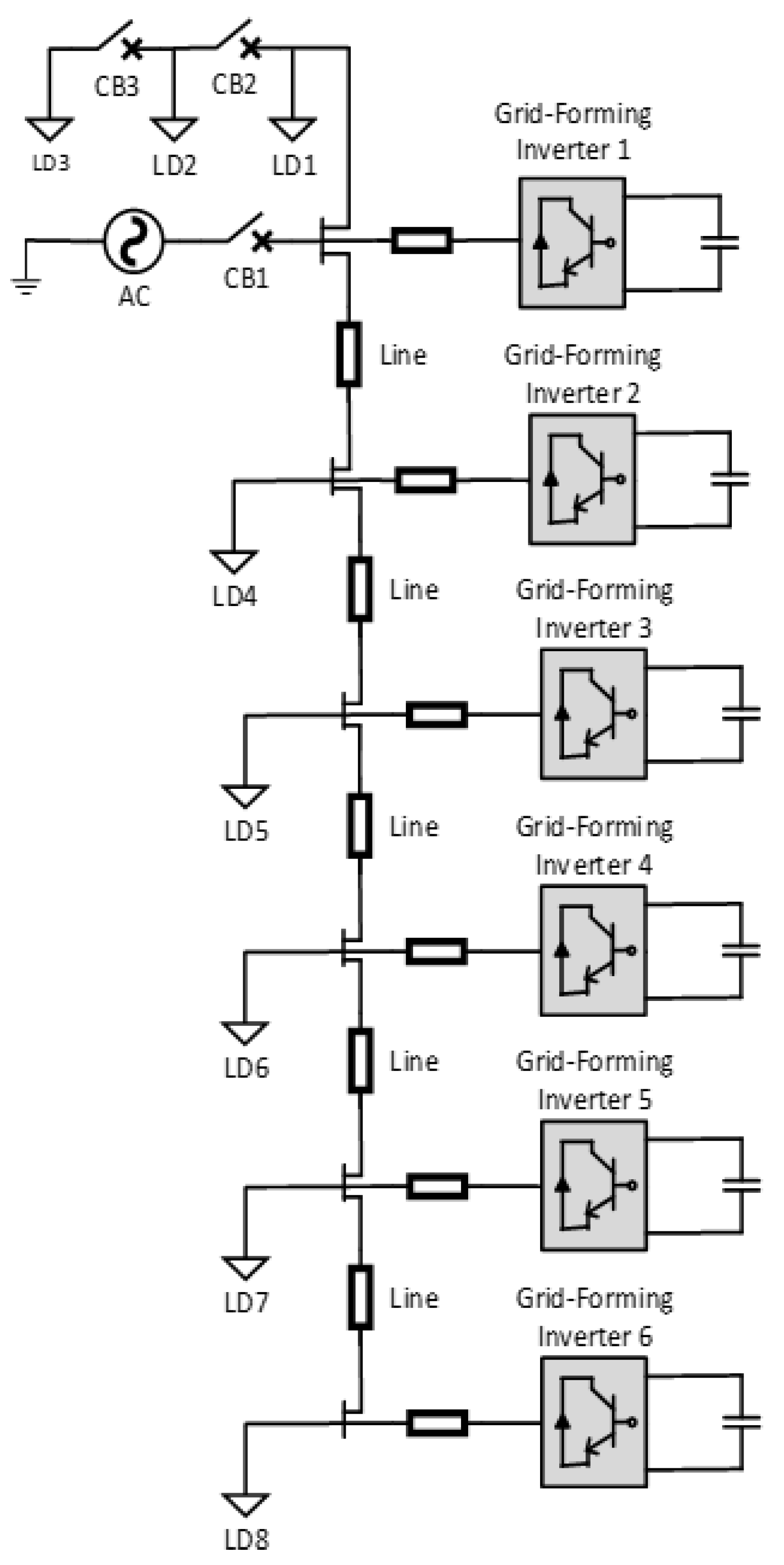
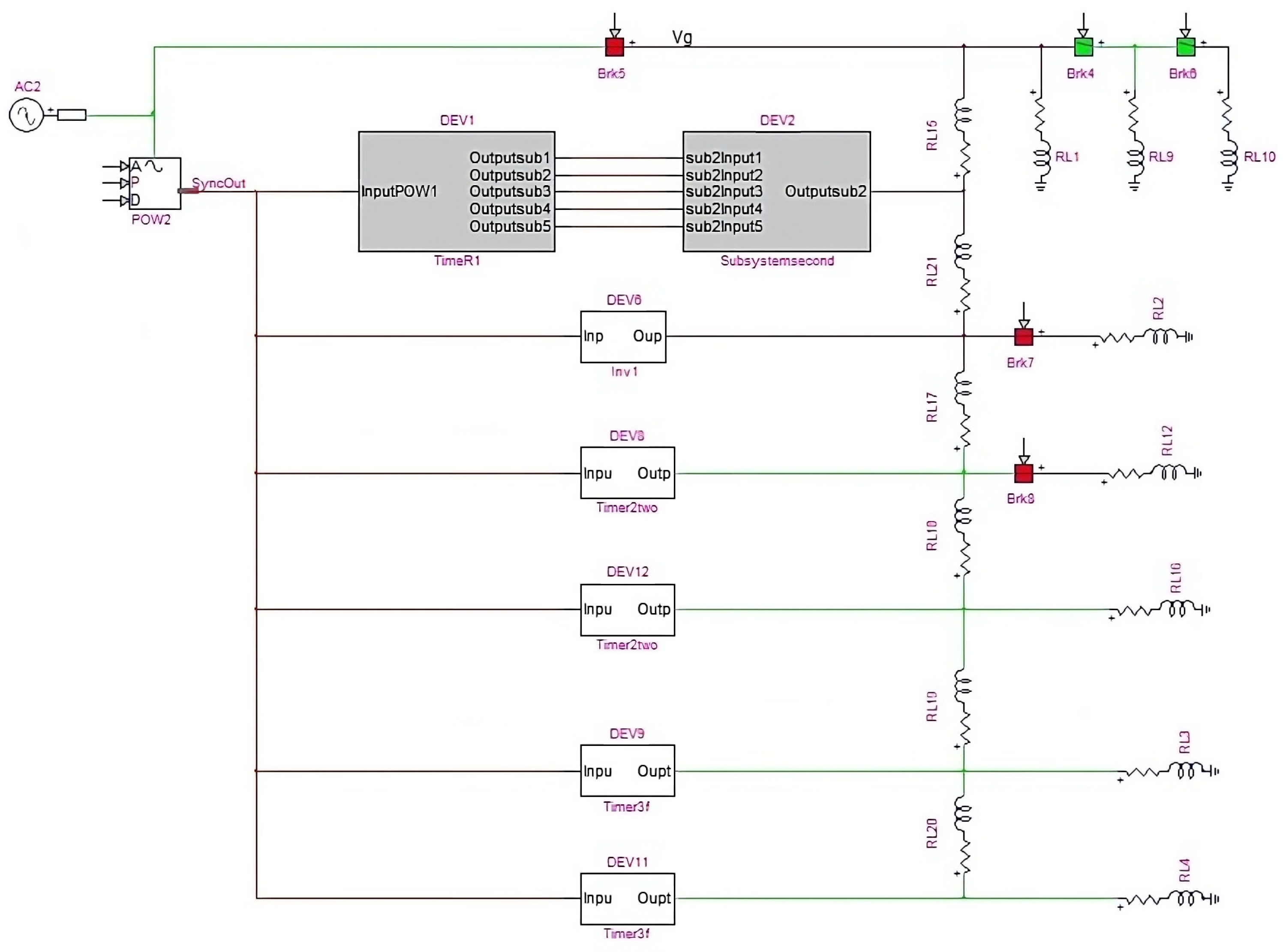
The droop coefficients are n = 2 and m = 3 with K e = 20, E * = 1, S = 1, and ω * = 377 [18,33,34]. The simulation is set up to test the operation of the GFM power inverter controller when grid-connected and grid-disconnected. The AC microgrid can be in island mode when CB1 is off, as shown in Figure 3, which is the same breaker Brk5 as in Figure 4, where the detailed model is in the real-time simulator. At time t = 0, the self-synchronization stage for six GFM power converter controllers with the grid occurs [18,34].
Table 1 presents the parameter design guidelines for each GFM inverter controller, providing a comprehensive overview of key parameters and their corresponding values. This table aims to provide a comprehensive set of control and circuit parameters for a thorough understanding of the GFM inverter controller, ensuring completeness and clarity in the parameter design guidelines.
The presence of the AC source in Figure 4 symbolizes the representation of inverters operating in grid-connected mode.

3.4. Black Start Capability

After a significant disturbance or power outage, PV systems that use GFL inverters must wait for a signal from a synchronous generator to connect to the grid. GFM inverters based on the SUDC could demonstrate an essential benefit for grid modernization [63] by creating independence from fossil fuels and improving the restoration time [64]. The output terminals of a GFM power inverter act as a [16] voltage source, which allows one to obtain a duty cycle that will be the input of an average model of a DC–DC inverter that uses controlled voltage and current sources. High penetration of PV systems by adapting DERs with GFL and GFM inverter controllers can result in voltage instability [18]. Nevertheless, the intermittent nature of the PV system is the reason for voltage fluctuations in the grid-connected PV system. Therefore, the passing of clouds and the angle of incidence also play a significant role in driving the system to instability through voltage fluctuations. The voltage profile and real power index can be affected by increasing the PV penetration levels with GFM inverters because the stress of the transmission lines decreases. At the same time, the loads are energized directly from the DERs. Penetration is defined as the nameplate PV power rating ratio to the maximum load observed by the distribution feeder, as shown in (11).
P V   p e n e t r a t i o n = T o t a l   P V   G e n e r a t i o n   ( M W )   T o t a l   G e n e r a t i o n   ( M W )

4. Case Study

The performance of the proposed adoption that mimics a virtual synchronous generator [65] to enable ancillary services such as voltage and frequency regulation, including the black start capability, were presented for six GFM inverter controllers in a small network and a test feeder with a 300-node system.

Modeling and Analysis

CASE I: Six GFM Inverter Controllers in A Small Network on A Real-Time Simulation Tool
The schematic model of the six GFM inverter controllers is shown in Figure 3, where the six GFM inverter controllers are placed in parallel with their loads (LD1, LD4, LD5, LD6, LD7, and LD8). CB1 was used to analyze the controllers on- and off-grid. In contrast, CB2 and CB3 connected two loads, LD2 and LD3. This same model is presented on the electromagnetic transient (EMT) real-time simulator, as shown in Figure 4. The first GFM inverter controller is shown with its timer block, and the other GFM power inverter controllers are presented as subsystems.
CASE II: Six GFM Inverter Controllers in A Test Feeder on The Real-Time Simulator
The IEEE 123 bus test feeder was designed to model six GFM inverter controllers in a 300-node system. The system consists of single-, two-, and three-phase lines. Eleven breakers were used [34] to set up the system as multiple islands. This feeder operates at a nominal [9] voltage of 4.16 kV. The bus numbers in the figure are distributed sequentially by each node cell. While the bigger bus numbers identify substations or buses connected to breakers. The total load of the system is 3.5 MW and 1.92 MVAr. Figure 5 shows the six GFM inverter controllers distributed in the IEEE 123 test feeder.

5. Case Studies Results

5.1. Results for Case Study I

5.1.1. Grid-Connected and Islanded Mode

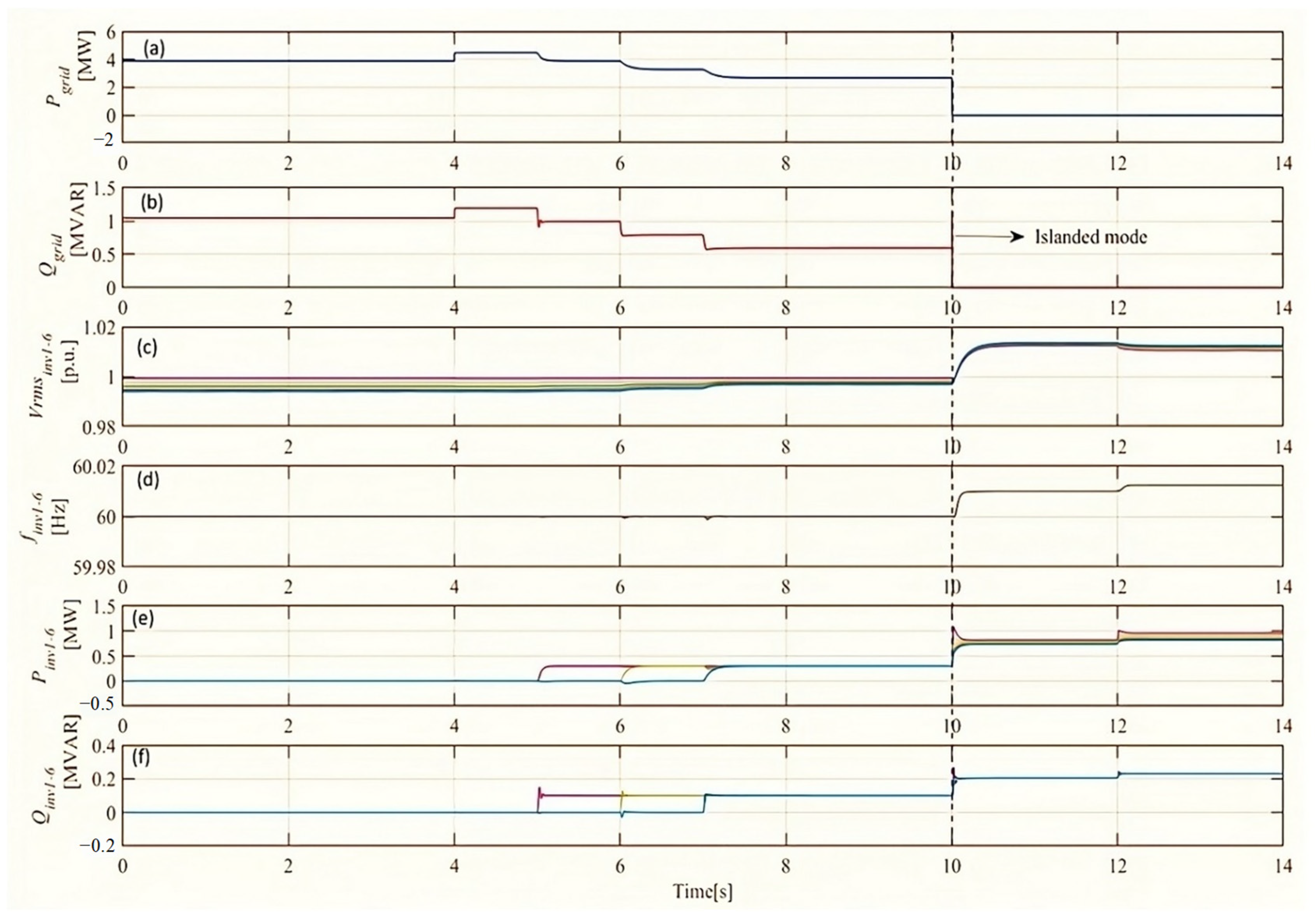
The [7] performance of a three-phase power inverter control in a small network on a real-time simulation tool is shown in Figure 6.
HYPERSIM, as a real-time simulation tool for grid-forming inverter controllers, offers the advantages of accuracy, real-time simulation capability, HIL testing, scalability, system integration, model development and customization, validation, and verification, as well as visualization and analysis. These benefits make HYPERSIM a valuable tool for studying, developing, and optimizing the control strategies of grid-forming inverters in a power system context. Synchronization is achieved when switch Sc is at position s, as shown in Figure 2, in position s and keeping switches SP and SQ open [34]. Initially, the real power set point, P s e t , and reactive power set point, Q s e t , values are fixed at 0 p.u. After 3 s, when all controllers have reached self-synchronization, switch Sc changed to position g. When t = 4 s, a load is added by closing the circuit breaker, CB2 is shown in Figure 3, and the same breaker is shown as Brk5 in Figure 4 [18,34]. Figure 6a and b shows the AC source’s real and reactive powers, respectively. The use of a real-time simulation ensures that the six inverters are operated in grid-following/feeding mode and are ready to supply power to the microgrid [18,34,61]. In the Figure 6 colorful lines were used to indicate the real power of the grid, reactive power of the grid and each of the 6 inverters.
The GFM power inverter controllers are set to 0.3 p.u. real power and 0.1 p.u. reactive power at different time instances. At t = 5 s, controllers 1 and 2 have these settings. At t = 6 s, controllers 3 and 4 have the same settings. Finally, at t = 7 s, controllers 5 and 6 are also set to the same values [34]. The voltage of all GFM power inverter controllers is shown in Figure 6c; while Figure 6d shows the frequency with a variation in some frequencies at times 5 s, 6 s, and 7 s; the similar case for the real and reactive powers are shown in Figure 6e and Figure 6f, respectively. Here, we show that the P s e t and Q s e t values are the real and reactive power values of the GFM power inverter controllers. The simulations show an accurate following of the six inverter controllers to the set points in grid-connected mode. A scenario is created at t = 10 s, where CB1 at the substation is opened intentionally to test the droop control in the islanded-mode operation of the microgrid [66]. When the source is disconnected, no power flows from it. When SP and SQ are ON, the GFM power inverter controllers are operated in droop control mode, as shown in Figure 2 [18,34]. During off-grid operation, the six GFM inverter controllers pick up the loads [67] while maintaining grid stability. Note that the voltages at the GFM power inverter controllers increase because the power set points automatically increase owing to the drop in active power output from the grid, as shown in Figure 6e,f, from 10 s to 14 s when the system is in islanded mode. The voltage and frequency were well regulated during the entire island mode operation, with a tension variation within ±5% [68] and a frequency variation within ±0.5% [18,34].

5.1.2. Black Start Capability on Grid-Disconnected Mode

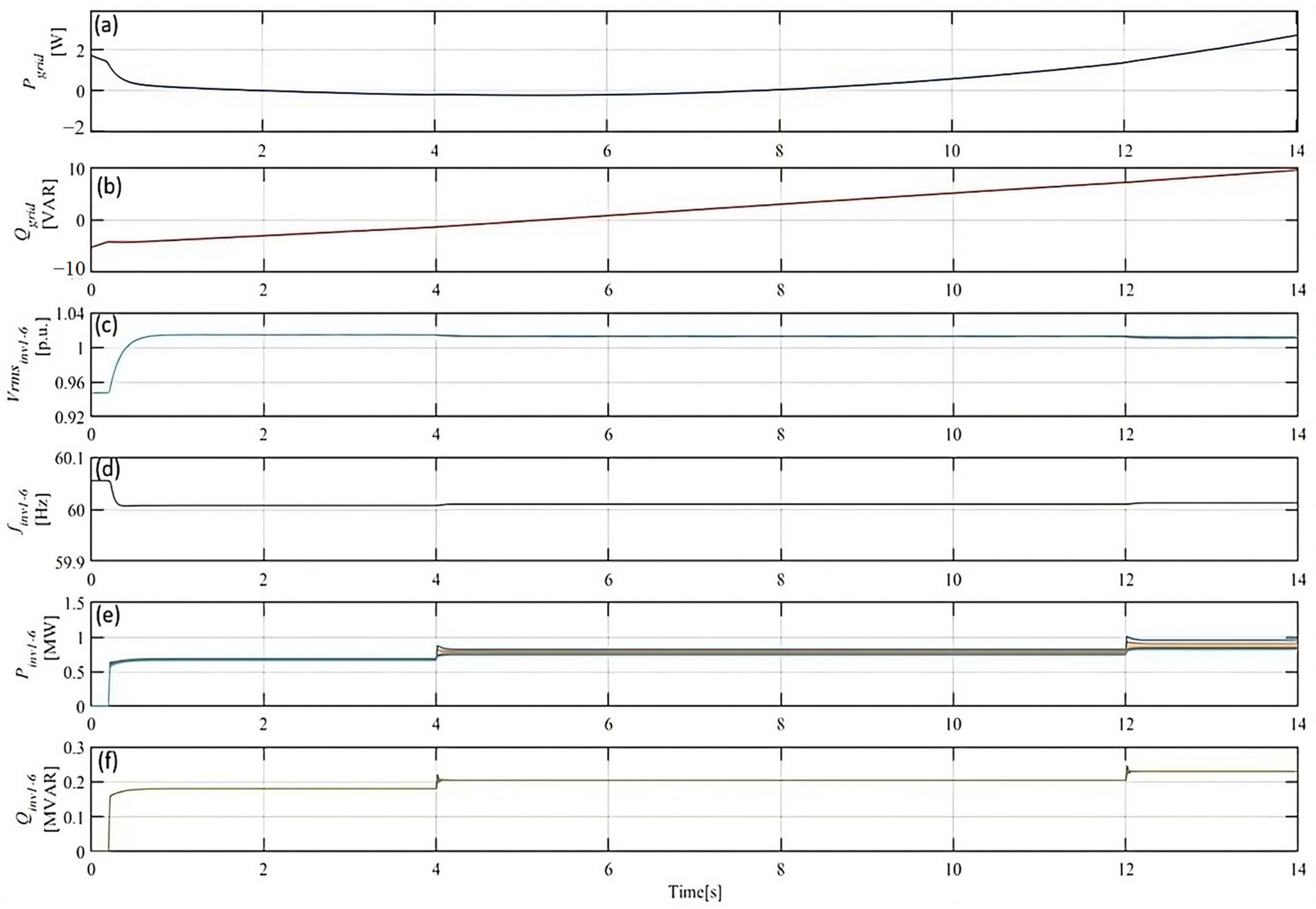
Black start is essential when no grid is available, and generators must perform cold-load pick-up whenever generation is available [69,70]. Specifically, because of their intermittent nature, GFM power inverter controllers must have black start capabilities. There might be cases when no grid is available, for example, after a natural disaster, and intermittent generation along with batteries could be the only available generation source for days [71]. The black start cases are shown in Figure 7 when the synchronization can be achieved within 0.2 s without any voltage overshoot for the GFM power inverter controllers. In Figure 7a,b, the real power and reactive power of the AC source are illustrated. At time points t = 4 s and t = 12 s, it is evident from Figure 7c,d that the loads experience minimal changes in frequency and voltage. Figure 7e,f demonstrates the effective response of the inverters in accommodating the additional loads introduced to the system.
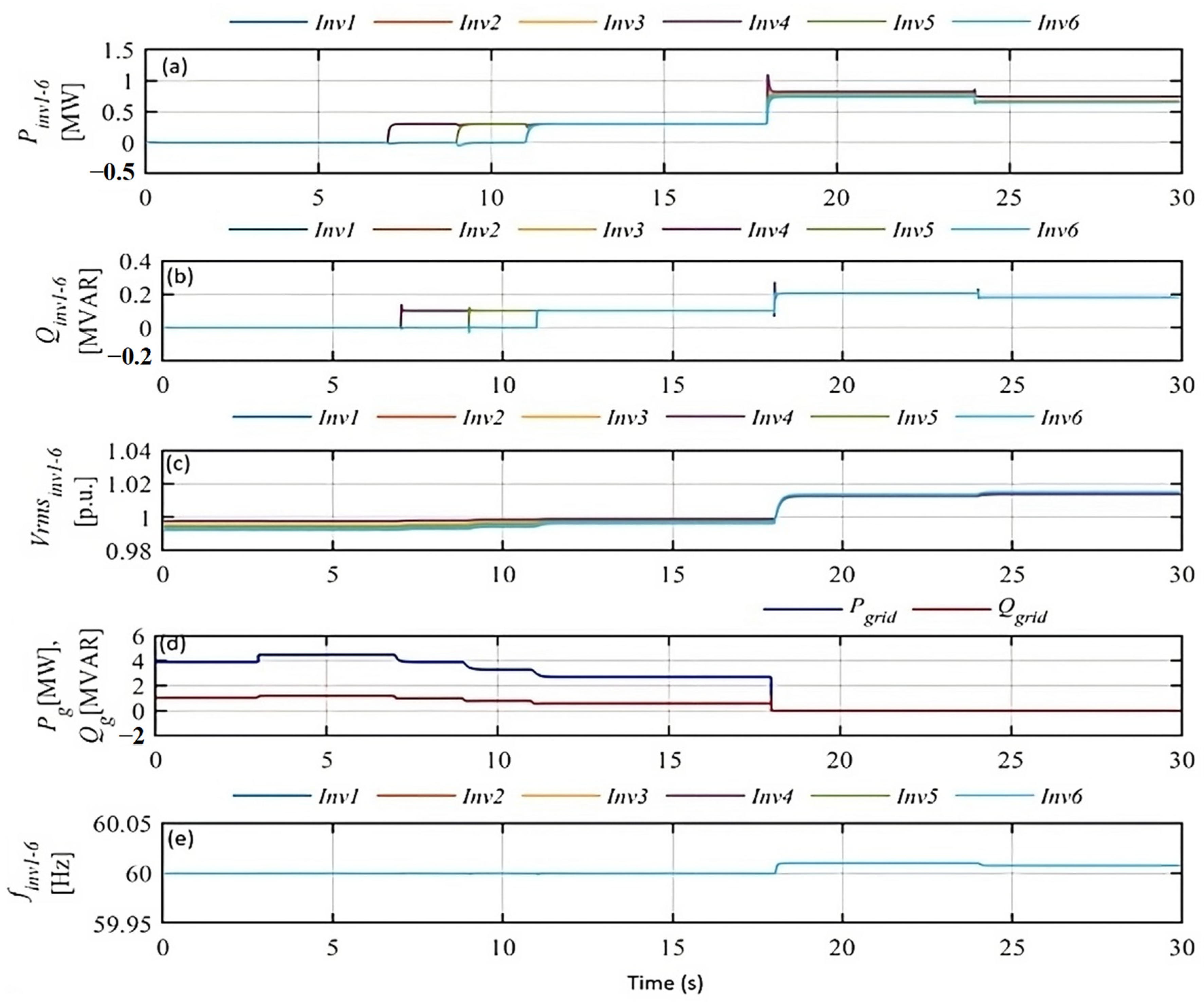
In this case, after 3 s of achieving self-synchronization for the six inverters, switch S is connected to position g [34]. When t = 4 s, a load is added by closing the circuit breaker, CB2 [18,34]. This ensures that the six inverters are operated in GFL/feeding mode and are ready to supply power to the microgrid [18,72]. When t = 7 s for inverters 1 and 2: real power set = 0.3 p.u. and reactive power set = 0.1 p.u.; when t = 9 s for inverters 3 and 4: real power set = 0.3 p.u. and reactive power set = 0.1 p.u. And, when t = 11 s for inverters 5 and 6: real power set = 0.3 p.u. and reactive power set = 0.1 p.u.

5.2. Results for Case Study II

5.2.1. Performance of Six GFM Inverter Controllers in Grid-Connected and Islanded Modes in the Test Feeder

The results of the scalable GFM inverter controller show the proper performance of the six inverter controllers in grid-connected mode at the set points. During the grid connection, the six GFM inverters pick up the load while maintaining the grid stability. At t = 7 s, t = 9 s, and t = 11 s, the voltages (p.u.) at the GFM inverters pick up the loads observed in each node cell by turning on the switches. In the Figure 7 colorful lines were used to indicate the real power of the grid, reactive power of the grid and each of the 6 inverters.
The performance of the voltages regulated by the real power at these specified times is shown in Figure 8. Similarly, the frequency performance is regulated by reactive power. At t = 18 s, CB1 at the substation is opened to test the droop control in the island mode operation of the AC microgrid. It can be observed that when the source is disconnected, no power flows from the source, and the GFM inverter controller operates in the droop control mode [18,32,34]. The proposed adoption of the GFM power inverter controller shows the ability to regulate voltage and frequency while keeping these values within the specified ranges [68,73,74]. The frequency system is shown in Figure 8e, establishing the entire behavior of the six GFM power inverter controllers, maintaining the frequency stabilization within ±0.5%.
Table 2 highlights the differences between placing six GFM inverters in a small network and placing them in the IEEE 123-node test feeder.

5.2.2. Black Start Capability of Six GFM Inverter Controllers in the IEEE 123 Test Feeder

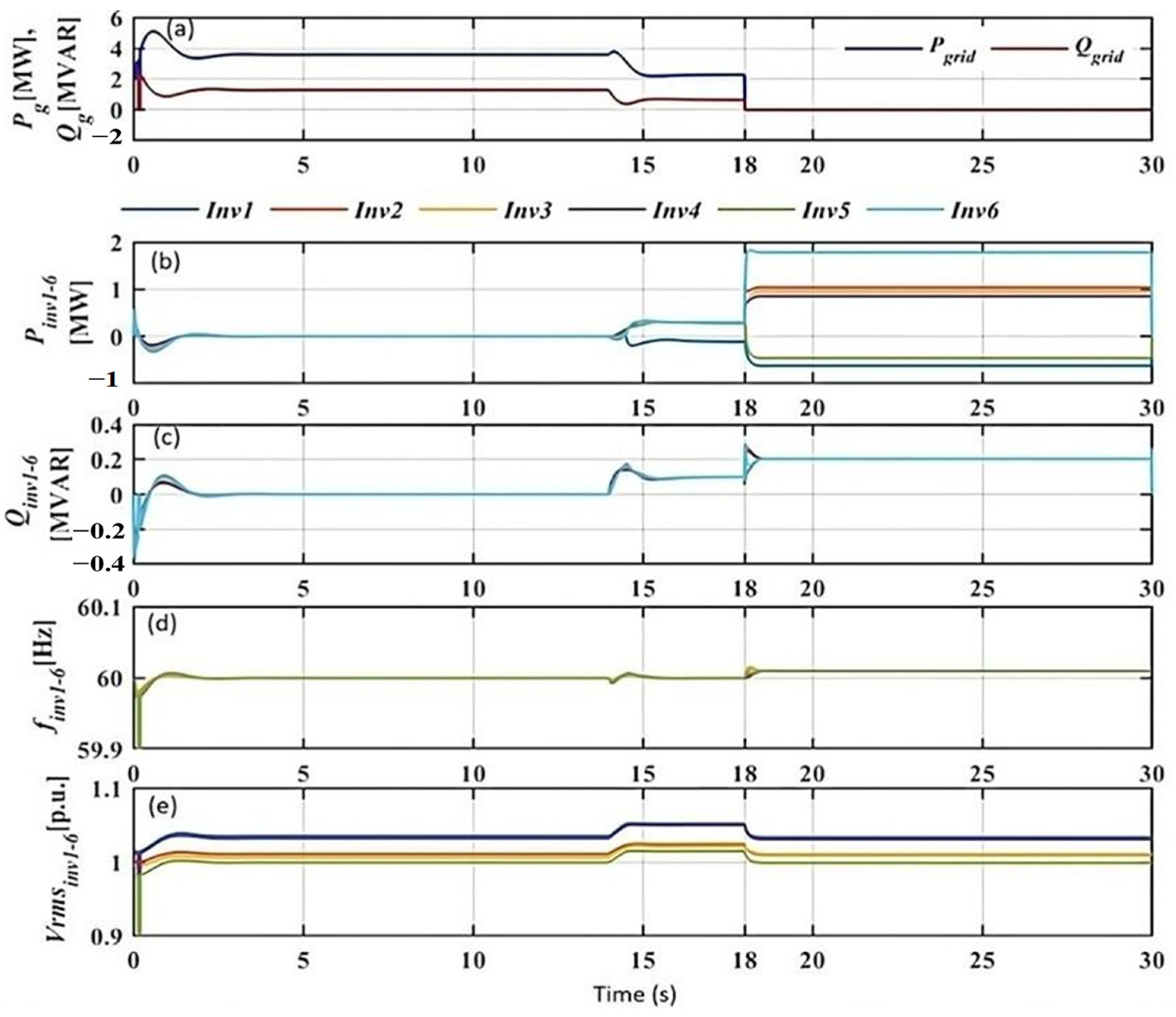
At t = 0 s, without power, it can be demonstrated that the black start capability is achieved within 0.2 s without any voltage overshoot. Then, the grid is connected, and at time t = 14 s, two loads are added to the system, as shown in Figure 9a.
Then, the GFM power inverter controller can pick up the loads, as shown in Figure 9b,c, with hardly any change in frequencies and voltages, as observed in Figure 9d,e, respectively. The synchronization was achieved at t = 18 s until t = 30 s when the grid was disconnected, and the GFM power inverter controllers were in droop mode. Table 2 shows the table of the evaluated GFM inverter controller for two different electrical networks.

6. Discussion

As we move towards global decarbonization and energy independence, millions of GFM inverters in the electrical grid will convert various forms of renewable energy. These devices must exhibit the proper functionality and interoperability in both steady-state and transient conditions on the electrical grid. However, obtaining only one detailed inverter model and control parameters under all conditions for grid-connected and grid-disconnected modes is difficult while promoting GFM power inverter technology innovations. This paper showed grid-originated disturbances and detected the response of the GFM inverter controller. Adopting the GFM power inverter controller provided an optimal advance in their performance to continue working on the scalability study of the GFM power inverter controller to monitor and validate the model’s flexibility in large-scale distribution systems. Based on the investigated designs for the GFM power inverter controller, this study explored different gaps from other studies: sufficient dynamics in scalability studies using many nodes and including all dynamics and faults with breakers is challenging. Several simulation results were obtained to evaluate the performance of the proposed three-phase GFM power inverter controller used in grid-connected and islanded photovoltaic microgrids. This study demonstrates the successful performance of the three-phase GFM power inverter controller for grid-connected and islanded PV microgrids.
A small network with limited available generation resources and simplified system protection would be easier to maintain and have simpler power flow management. On the other hand, a large network like an IEEE 123-node test feeder with abundant generation resources and extensive system protection would be more challenging to maintain and demand more from power flow management. Additionally, the IEEE 123-node test feeder has a more complex grid and requires more comprehensive fault analysis. The communication requirements are also more demanding, and integration with existing systems is more complex. Finally, system modeling and simulation are less detailed for a small network but more extensive for the IEEE 123-node test feeder.
GFM inverters offer several advantages when utilized in the IEEE 123-node test feeder. This research paper explores these advantages, which include enhanced power quality, increased resilience, flexibility in generation sources, improved grid support, demand response integration, smoother transitions and islanding capability, and advanced monitoring and control. One notable advantage is the enhanced power quality achieved through GFM inverters’ advanced control capabilities. These inverters actively regulate voltage and frequency, leading to improved power quality in the system. By maintaining stable voltage levels, minimizing voltage sags and swells, and reducing harmonic distortion, GFM inverters contribute to a more reliable and efficient power supply. Incorporating grid-forming inverters also enhances the system’s resilience to disturbances and faults. These inverters can respond quickly to changes in demand and supply, allowing for better system stability and faster recovery from disruptions. Their ability to dynamically adjust power output and respond to grid conditions ensures a more robust and reliable power distribution system. GFM inverters enable the integration of various DERs into the system, providing flexibility in generation sources. This allows for a diverse mix of generation sources, including renewable energy systems like solar and wind. By facilitating the integration of DERs, GFM inverters promote cleaner and more sustainable power generation, contributing to environmental sustainability. Furthermore, GFM inverters actively provide reactive power support and voltage regulation to the system. This capability improves grid stability, particularly in scenarios involving voltage fluctuations or low power factor. By regulating voltage and reactive power, these inverters help maintain grid stability and optimize power flow. The integration of demand response programs is another advantage of GFM inverters. These inverters can respond to signals from the grid operator and adjust power output or demand accordingly. By facilitating demand response integration, GFM inverters enable better management of load profiles and promote more efficient utilization of energy resources. GFM inverters also offer smoother transitions and islanding capability. They facilitate seamless transitions between grid-connected and island modes of operation. In the event of a grid outage or intentional islanding, these inverters can continue supplying power locally, ensuring system stability and enabling microgrid operations. This capability enhances overall system reliability and resilience. Additionally, GFM inverters often come equipped with advanced monitoring and control features. These features allow for real-time monitoring of system parameters, fault detection, and adaptive control strategies. By providing comprehensive monitoring and control capabilities, GFM inverters contribute to improved system performance and optimized operation.
The utilization of GFM inverters in the IEEE 123-node test feeder offered significant advantages. These include enhanced power quality, increased resilience, flexibility in generation sources, improved grid support, demand response integration, smoother transitions and islanding capability, and advanced monitoring and control. These advantages contribute to the development of more reliable, efficient, and sustainable power distribution systems. Experimental studies were conducted to affirm the efficacy of the proposed method; however, this paper primarily emphasizes simulation results to validate the scalability of the proposed GFM inverter controller technology. The inclusion of further validations would contribute to enhancing the overall robustness and coherence of this study.

7. Conclusions

In this study, we first proposed and evaluated the current situation with an electrical grid, which leverages the idea of decarbonizing the grid using GFM power inverters. Based on the dependency pattern of GFL inverters and the adoption of the most recent GFM inverter controller in a small electrical network and a large-scale test feeder, the proposed adoption model can effectively regulate the voltage and frequency in grid-connected and islanded photovoltaic microgrids. The proposed adoption of the GFM power inverter controller not only helps to reduce dependence on fossil fuels, but also enhances the penetration index of DERs into the grid by scaling the appropriate number of GFM inverters. In future work, we plan to apply the proposed adoption using 60 GFM power inverter controllers and another test feeder grid with more electrical nodes.
This paper has delivered significant quantitative insights through rigorous analysis and evaluation:
  • Dependency Pattern Analysis:
  • Proposed and systematically evaluated the current state of an electrical grid with a focus on decarbonization using GFM power inverters.
  • Quantified the dependency pattern of GFL inverters, providing a clear understanding of their role within the grid.
  • Voltage and Frequency Regulation:
  • Implemented and assessed a novel adoption model incorporating the latest GFM inverter controller in both small electrical networks and large-scale test feeders.
  • Quantitatively demonstrated the model’s efficacy in regulating voltage and frequency in grid-connected and islanded photovoltaic microgrids.
  • Fossil Fuel Dependence Reduction:
  • Quantified the tangible impact of adopting GFM power inverter controller, showcasing a measurable reduction in dependence on fossil fuels.
  • Established the paper’s contribution in steering the grid towards cleaner and more sustainable energy sources.
  • Enhanced DER Penetration Index:
  • Evaluated, in quantitative terms, how the GFM power inverter controller enhances the penetration index of DERs into the grid.
  • Provided numerical insights into the scalability of the adoption model, determining the optimal number of GFM inverters for effective DER integration.
  • Future Scaling Plans:
  • Outlined a concrete plan for future work, involving the application of the proposed adoption model using 60 GFM power inverter controller.
  • Anticipated quantitative outcomes from an additional test feeder grid with more electrical nodes, promising a deeper understanding of scalability and performance.
These refined quantitative results underscore this paper’s contribution, providing a robust foundation for conclusions drawn from a thorough and data-driven examination of GFM power inverter adoption within electrical grids.
Certainly, expanding the scope of future work can bring about a more comprehensive exploration of the implications and potential advancements related to the present study. Consider the following perspectives for future work:
  • Advanced Control Strategies:
  • Investigate and implement more advanced control strategies for GFM power inverter controllers beyond the current technology. Explore predictive control methods or artificial intelligence-based approaches to further enhance grid stability and performance.
  • Cybersecurity Considerations:
  • Address the growing importance of cybersecurity in the context of GFM power inverters. Assess vulnerabilities and propose robust security measures to protect against potential cyberthreats, ensuring the resilience of the grid.
  • Integration of Energy Storage:
  • Explore the integration of energy storage systems in conjunction with GFM power inverters. Investigate how energy storage technologies can be synergistically employed to enhance grid reliability, mitigate intermittency issues, and support continuous power supply during fluctuations.
  • Resilience to Extreme Events:
  • Evaluate the resilience of GFM power inverter systems to extreme weather events, natural disasters, and other unforeseen challenges. Develop strategies to ensure grid continuity and rapid recovery in the face of adverse conditions.
  • GFM in Hybrid Systems:
  • Investigate the role of GFM power inverters in hybrid energy systems, where multiple energy sources (renewable and conventional) coexist. Analyze their performance in complex grid architectures and assess the potential for improved hybrid system optimization.
  • Economic Viability and Cost–Benefit Analysis:
  • Conduct a comprehensive economic analysis to assess the cost-effectiveness of widespread GFM power inverter adoption. Explore potential incentives, subsidies, and cost savings associated with reduced reliance on traditional power generation methods.
  • Real-World Implementation and Case Studies:
  • Collaborate with utility providers or relevant stakeholders to implement GFM power inverter systems in real-world scenarios. Conduct case studies to validate the scalability, reliability, and performance under actual grid conditions.
  • Policy and Regulatory Considerations:
  • Examine the existing policy and regulatory frameworks governing the integration of GFM power inverters. Propose recommendations for policy adjustments or regulatory updates to encourage and facilitate their widespread deployment.
  • Quantification of Environmental Impact:
  • Quantify the environmental impact of adopting GFM power inverters compared to traditional grid configurations. Assess the reduction in carbon emissions and other environmental benefits associated with the transition to cleaner energy sources.
  • Public Awareness and Stakeholder Engagement:
  • Develop strategies to enhance public awareness and engage relevant stakeholders in the adoption of GFM power inverters. Investigate public perception, potential barriers, and methods to promote acceptance and collaboration.
These diverse perspectives for future work can contribute to a more holistic understanding of the implications and applications of GFM power inverters, paving the way for advancements in grid modernization and sustainable energy integration.

Author Contributions

Conceptualization, L.W. and A.S.; methodology, L.W. and M.C.; software, L.W. and M.C.; validation, L.W., M.C. and S.B.B.; formal analysis, L.W.; investigation, L.W. and A.S.; resources, A.D.; data curation, L.W. and M.C.; writing—original draft preparation, L.W. and A.S. A.D.; writing—review and editing, L.W. and A.S.; visualization, L.W.; supervision, S.B.B.; project administration, S.B.B. and M.C.; funding acquisition, M.C. and S.B.B. All authors have read and agreed to the published version of the manuscript.

Funding

This research was based on work supported by the U.S. Department of Energy’s Office of Energy Efficiency and Renewable Energy (EERE) under the Solar Energy Technologies Office Award Number DE-EE0009030. Disclaimer: This paper was presented as an account of work sponsored by an agency of the U.S. Government. Neither the United States Government nor any agency thereof, nor any of their employees, makes any warranty, express or implied, or assumes any legal liability or responsibility for the accuracy, completeness, or usefulness of any information, apparatus, product, or process disclosed or represents that its use would not be infringing on privately owned rights. Reference herein to any specific commercial product, process, or service by trade name, trademark, manufacturer, or otherwise does not necessarily constitute or imply its endorsement, recommendation, or favoring by the United States Government or any agency thereof. The views and opinions of the authors expressed herein do not necessarily state or reflect those of the United States Government or any agency thereof.

Institutional Review Board Statement

Not applicable.

Informed Consent Statement

Not applicable.

Data Availability Statement

The data presented is available on request from the corresponding author.

Acknowledgments

The authors appreciate the support of the U.S. Department of Energy for funding this work. The authors thank Qing-Chang Zhong for his invaluable advice and contribution to this work. The authors also acknowledge the computational resources provided by OPAL-RT, as well as the National Wind Institute at Texas Tech University.

Conflicts of Interest

The authors declare no conflicts of interest. The funders had no role in the design of the study; in the collection, analyses, or interpretation of data; in the writing of the manuscript; or in the decision to publish the results.

References

  1. Breyer, C.; Khalili, S.; Bogdanov, D.; Ram, M.; Oyewo, A.S.; Aghahosseini, A.; Gulagi, A.; Solomon, A.A.; Keiner, D.; Lopez, G.; et al. On the History and Future of 100% Renewable Energy Systems Research. IEEE Access 2022, 10, 78176–78218. [Google Scholar] [CrossRef]
  2. Shen, B.; Kahrl, F.; Satchwell, A.J. Facilitating Power Grid Decarbonization with Distributed Energy Resources: Lessons from the United States. Annu. Rev. Environ. Resour. 2021, 46, 349–375. [Google Scholar] [CrossRef]
  3. Hossain, M.B.; Islam, M.R.; Muttaqi, K.M.; Sutanto, D.; Agalgaonkar, A.P. Modeling and performance analysis of renewable hydrogen energy hub connected to an ac/dc hybrid microgrid. Int. J. Hydrogen Energy 2022, 47, 28626–28644. [Google Scholar] [CrossRef]
  4. Satymov, R.; Bogdanov, D.; Breyer, C. The Value of Fast Transitioning to a Fully Sustainable Energy System: The Case of Turkmenistan. IEEE Access 2021, 9, 13590–13611. [Google Scholar] [CrossRef]
  5. Burton, R.; Baggu, M.; Rhodes, J.; Blair, N.; Harris, T.; Sengupta, M.; Barrows, C.; Sky, H.; Yang, J.; Elsworth, J.; et al. Puerto Rico Grid Resilience and Transitions to 100% Renewable Energy Study (pr100): Six-Month Progress Update; Technical Report; National Renewable Energy Lab (NREL): Golden, CO, USA, 2022.
  6. U.S. Energy Information Administration. Us Energy Information Administration Annual Energy Outlook 2020; US Department of Energy: Washington, DC, USA, 2020.
  7. Barrueto, A.; Díaz, M.; Chávez, H. An Overview of Challenges related to Power-Electronics Based Power Systems. In Proceedings of the 2021 IEEE International Conference on Automation/XXIV Congress of the Chilean Association of Automatic Control (ICA-ACCA), Valparaíso, Chile, 22–26 March 2021; pp. 1–7. [Google Scholar] [CrossRef]
  8. Multnomah County-Sustainability, “100% Renewable by 2050”. 2017. Available online: https://www.multco.us/sustainability/100-renewable-2050 (accessed on 12 July 2023).
  9. Bassey, O.; Butler-Purry, K.L.; Chen, B. Dynamic Modeling of Sequential Service Restoration in Islanded Single Master Microgrids. IEEE Trans. Power Syst. 2020, 35, 202–214. [Google Scholar] [CrossRef]
  10. Saadatmand, S. Advanced Control Techniques for Modern Inertia-Based Inverters. Ph.D. Dissertation, Missouri University of Science and Technology, Rolla, MO, USA, 2021. [Google Scholar]
  11. Zhong, Q.-C. Power-Electronics-Enabled Autonomous Power Systems: Architecture and Technical Routes. IEEE Trans. Ind. Electron. 2017, 64, 5907–5918. [Google Scholar] [CrossRef]
  12. Rathnayake, D.B.; Akrami, M.; Phurailatpam, C.; Me, S.P.; Hadavi, S.; Jayasinghe, G.; Zabihi, S.; Bahrani, B. Grid forming inverter modeling, control, and applications. IEEE Access 2021, 9, 114781–114807. [Google Scholar] [CrossRef]
  13. Pattabiraman, D. Impact of Inverter Control on the Dynamic Performance of Power Systems with High Penetration of Inverter-Based Resources; The University of Wisconsin-Madison: Madison, WI, USA, 2020. [Google Scholar]
  14. Zhong, Q.-C.; Nguyen, P.-L. Sinusoid-locked loops based on the principles of synchronous machines. In Proceedings of the 2012 24th Chinese Control and Decision Conference (CCDC), Taiyuan, China, 23–25 May 2012; pp. 1518–1523. [Google Scholar] [CrossRef]
  15. Zhong, Q.-C.; Nguyen, P.-L.; Ma, Z.; Sheng, W. Self-Synchronized Synchronverters: Inverters Without a Dedicated Synchronization Unit. IEEE Trans. Power Electron. 2013, 29, 617–630. [Google Scholar] [CrossRef]
  16. Tuckey, A.; Round, S. Grid-forming inverters for grid-connected microgrids: Developing “good citizens” to ensure the continued flow of stable, reliable power. IEEE Electrif. Mag. 2022, 10, 39–51. [Google Scholar] [CrossRef]
  17. Yap, K.Y.; Sarimuthu, C.R.; Lim, J.M.-Y. Virtual Inertia-Based Inverters for Mitigating Frequency Instability in Grid-Connected Renewable Energy System: A Review. Appl. Sci. 2019, 9, 5300. [Google Scholar] [CrossRef]
  18. U. D. of Energy, O. o. S. Information, and Technical. Large-Scale Adoption of Self-Synchronized Universal Droop Controller Based Inverters to Enable Ancillary Services for Different Modes of Distribution System Operations. 2020. Available online: https://www.osti.gov/biblio/1733353 (accessed on 6 February 2024).
  19. Lasseter, R.H.; Chen, Z.; Pattabiraman, D. Grid-forming inverters: A critical asset for the power grid. IEEE J. Emerg. Sel. Top. Power Electron. 2020, 8, 925–935. [Google Scholar] [CrossRef]
  20. Rampokanyo, M.; Dattaray, P.; Kamera, P.; Beerten, J.; Aronovich, I.; Corcoran, D.; Bos, J.; Modi, N.; Rahimi, I.; Quint, R.; et al. Impact of high penetration of inverter-based generation on system inertia of networks. Electra 2021, 319, 1–13. [Google Scholar]
  21. Du, W.; Tuffner, F.K.; Schneider, K.P.; Lasseter, R.H.; Xie, J.; Chen, Z.; Bhattarai, B. Modeling of grid-forming and grid-following inverters for dynamic simulation of large-scale distribution systems. IEEE Trans. Power Deliv. 2020, 36, 2035–2045. [Google Scholar] [CrossRef]
  22. Zuo, Y.; Yuan, Z.; Sossan, F.; Zecchino, A.; Cherkaoui, R.; Paolone, M. Performance assessment of grid-forming and grid-following converter-interfaced battery energy storage systems on frequency regulation in low-inertia power grids. Sustain. Energy Grids Netw. 2021, 27, 100496. [Google Scholar] [CrossRef]
  23. Lu, M. Virtual oscillator grid-forming inverters: State of the art, modeling, and stability. IEEE Trans. Power Electron. 2022, 37, 11579–11591. [Google Scholar] [CrossRef]
  24. Quedan, D.A.; Ramasubramanian, D.; Farantatos, E. Virtual Oscillator Controlled Grid Forming Inverters Modelling and Testing in Phasor Domain. In Proceedings of the 2021 IEEE 12th Energy Conversion Congress & Exposition—Asia (ECCE-Asia), Singapore, 24–27 May 2021; pp. 2375–2380. [Google Scholar] [CrossRef]
  25. Hadjileonidas, A.; Li, Y.; Green, T.C. Comparative analysis of transient stability of grid-forming and grid-following inverters. In Proceedings of the 2022 IEEE International Power Electronics and Application Conference and Exposition (PEAC), Guangzhou, China, 4–7 November 2022; pp. 296–301. [Google Scholar]
  26. Song, G.; Cao, B.; Chang, L. Review of Grid-forming Inverters in Support of Power System Operation. Chin. J. Electr. Eng. 2022, 8, 1–15. [Google Scholar] [CrossRef]
  27. Lin, Y.; Eto, J.H.; Johnson, B.B.; Flicker, J.D.; Lasseter, R.H.; Villegas Pico, H.N.; Seo, G.S.; Pierre, B.J.; Ellis, A. Research Roadmap on Grid-Forming Inverters; Technical Report; National Renewable Energy Lab. (NREL): Golden, CO, USA, 2020.
  28. Du, W.; Singhal, A.; Tuffner, F.K.; Schneider, K.P. Comparison of Electromagnetic Transient and Phasor-based Simulation for the Stability of Grid-Forming-Inverter-based Microgrids. In Proceedings of the 2021 IEEE Power & Energy Society Innovative Smart Grid Technologies Conference (ISGT), Washington, DC, USA, 16–18 February 2021; pp. 1–5. [Google Scholar] [CrossRef]
  29. Aghdam, S.A.; Agamy, M. Virtual oscillator-based methods for grid-forming inverter control: A review. IET Renew. Power Gener. 2022, 16, 835–855. [Google Scholar] [CrossRef]
  30. Muhanji, S.O.; Muzhikyan, A.; Farid, A.M. Distributed Control for Distributed Energy Resources: Long-Term Challenges and Lessons Learned. IEEE Access 2018, 6, 32737–32753. [Google Scholar] [CrossRef]
  31. Photovoltaics, D.G.; Storage, E. IEEE standard for interconnection and interoperability of distributed energy resources with associated electric power systems interfaces. IEEE Stand. 2018, 1547, 1547–2018. [Google Scholar]
  32. Zhong, Q.C.; Ming, W.L.; Zeng, Y. Self-Synchronized Universal Droop Controller. IEEE Access 2016, 4, 7145–7153. [Google Scholar] [CrossRef]
  33. Ruan, Y.; Zhong, Q.-C. Wind power system control based on the self- synchronized universal droop controller. In Proceedings of the 2019 IEEE Energy Conversion Congress and Exposition (ECCE), Baltimore, MD, USA, 29 September–3 October 2019; pp. 4654–4659. [Google Scholar]
  34. Arce, L.; Chamana, M.; Osman, I.; Ren, B.; Zhong, Q.C.; Bayne, S. Large-Scale Adoption of Self-Synchronized Universal Droop Controller-Based Inverters to Enable Ancillary Services for Different Modes of Distribution System Operations. In Proceedings of the 2020 5th IEEE Workshop on the Electronic Grid (eGRID), Aachen, Germany, 2–4 November 2020; pp. 1–6. [Google Scholar] [CrossRef]
  35. Çelik, Ö.; Teke, A.; Tan, A. Overview of micro-inverters as a challenging technology in photovoltaic applications. Renew. Sustain. Energy Rev. 2018, 82, 3191–3206. [Google Scholar] [CrossRef]
  36. Nguyen, Q.; Vallem, M.R.; Vyakaranam, B.; Tbaileh, A.; Ke, X.; Samaan, N. Control and simulation of a grid-forming inverter for hybrid pv-battery plants in power system black start. In Proceedings of the 2021 IEEE Power & Energy Society General Meeting (PESGM), Washington, DC, USA, 26–29 July 2021; pp. 1–5. [Google Scholar] [CrossRef]
  37. Ansari, S.; Chandel, A.; Tariq, M. A Comprehensive Review on Power Converters Control and Control Strategies of AC/DC Microgrid. IEEE Access 2021, 9, 17998–18015. [Google Scholar] [CrossRef]
  38. Wang, S.; Qi, R.; Li, Y. Fuzzy Control Scheme of Virtual Inertia for Synchronverter in Micro-Grid. In Proceedings of the 2018 21st International Conference on Electrical Machines and Systems (ICEMS), Jeju, Republic of Korea, 7–10 October 2018; pp. 2028–2032. [Google Scholar] [CrossRef]
  39. Laaksonen, H. Universal Grid-Forming Method for Future Power Systems. IEEE Access 2022, 10, 133109–133125. [Google Scholar] [CrossRef]
  40. Qoria, T.; Rokrok, E.; Bruyere, A.; François, B.; Guillaud, X. A pll-free grid-forming control with decoupled functionalities for high-power transmission system applications. IEEE Access 2020, 8, 197363–197378. [Google Scholar] [CrossRef]
  41. Kjaer, S.; Pedersen, J.; Blaabjerg, F. A Review of Single-Phase Grid-Connected Inverters for Photovoltaic Modules. IEEE Trans. Ind. Appl. 2005, 41, 1292–1306. [Google Scholar] [CrossRef]
  42. Bahrani, B. Power-Synchronized Grid-Following Inverter Without a Phase-Locked Loop. IEEE Access 2021, 9, 112163–112176. [Google Scholar] [CrossRef]
  43. Ellis, A. Grid Forming Inverters in Interconnected Systems. 2019. Available online: https://der-lab.net/wp-content/uploads/2018/11/Ellis_GFI-Vienna.pdf (accessed on 1 June 2023).
  44. Butt, O.M.; Zulqarnain, M.; Butt, T.M. Recent advancement in smart grid technology: Future prospects in the electrical power network. Ain Shams Eng. J. 2021, 12, 687–695. [Google Scholar] [CrossRef]
  45. Lasseter, B. Microgrids [distributed power generation]. In Proceedings of the 2001 IEEE Power Engineering Society Winter Meeting. Conference Proceedings (Cat. No. 01CH37194), Columbus, OH, USA, 28 January–1 February 2001; Volume 1, pp. 146–149. [Google Scholar]
  46. Stadler, M.; Cardoso, G.; Mashayekh, S.; Forget, T.; DeForest, N.; Agarwal, A.; Schönbein, A. Value streams in microgrids: A literature review. Appl. Energy 2016, 162, 980–989. [Google Scholar] [CrossRef]
  47. Ton, D.T.; Smith, M.A. The us department of energy’s microgrid initiative. Electr. J. 2012, 25, 84–94. [Google Scholar]
  48. Hoff, S. US electric system is made up of interconnections and balancing authorities. In US Energy Information Administration: Today in Energy; U.S. Energy Information Administration: Washington, DC, USA, 2016. [Google Scholar]
  49. Negri, C.A.; Daneshvardehnavi, S.; Schmitt, K.E.K.; Nezhad, A.E.; Nardelli, P.H.J.; Bayne, S.; Giesselmann, M.G. Centralized Control Topology for PV Farms Shading Detection and GMPP Searching Restarting Condition. IEEE Access 2022, 10, 28991–29008. [Google Scholar] [CrossRef]
  50. Daneshvardehnavi, S.; Negri, C.A.; Schmitt, K.E.K.; Bayne, S.; Giesselmann, M. A case study for connecting bidirectional pev station for reactive power support to the GLEAMM prototype microgrid. In Proceedings of the 2021 IEEE Green Technologies Conference (GreenTech), Denver, CO, USA, 7–9 April 2021; pp. 19–25. [Google Scholar] [CrossRef]
  51. Demir, A.; Gutiérrez, L.F.; Namin, A.S.; Bayne, S. Solar irradiance prediction using transformer-based machine learning models. In Proceedings of the 2022 IEEE International Conference on Big Data (Big Data), Osaka, Japan, 17–20 December 2022; pp. 2833–2840. [Google Scholar]
  52. Younis, T.; Ismeil, M.; Hussain, E.; Orabi, M. Single-phase self-synchronized synchronverter with current-limiting capability. In Proceedings of the 2016 Eighteenth International Middle East Power Systems Conference (MEPCON), Cairo, Egypt, 27–29 December 2016; pp. 848–853. [Google Scholar]
  53. Paspatis, A.G.; Konstantopoulos, G.C. Current-limiting droop control with virtual inertia and self-synchronization properties. In Proceedings of the IECON 2017—43rd Annual Conference of the IEEE Industrial Electronics Society, Beijing, China, 29 October–1 November 2017; pp. 196–201. [Google Scholar]
  54. Hsieh, G.-C.; Hung, J. Phase-locked loop techniques. a survey. IEEE Trans. Ind. Electron. 1996, 43, 609–615. [Google Scholar] [CrossRef]
  55. Ma, Y.; Cao, W.; Yang, L.; Wang, F.; Tolbert, L.M. Virtual Synchronous Generator Control of Full Converter Wind Turbines with Short-Term Energy Storage. IEEE Trans. Ind. Electron. 2017, 64, 8821–8831. [Google Scholar] [CrossRef]
  56. Mohammed, N.; Ravanji, M.H.; Zhou, W.; Bahrani, B. Online Grid Impedance Estimation-Based Adaptive Control of Virtual Synchronous Generators Considering Strong and Weak Grid Conditions. IEEE Trans. Sustain. Energy 2022, 14, 673–687. [Google Scholar] [CrossRef]
  57. Soni, K.A.; Jaiswal, N.K.; Lokhandwala, M.A. Phase locked loop for single phase grid synchronization. In Proceedings of the 2018 2nd International Conference on Trends in Electronics and Informatics (ICOEI), Tirunelveli, India, 11–12 May 2018; pp. 1058–1063. [Google Scholar] [CrossRef]
  58. Jain, P.; Agarwal, V.; Muni, B.P. Hybrid Phase Locked Loop for Controlling Master-Slave Configured Centralized Inverters in Large Solar Photovoltaic Power Plants. IEEE Trans. Ind. Appl. 2018, 54, 3566–3574. [Google Scholar] [CrossRef]
  59. Schmitt, K.E.K.; Osman, I.; Bhatta, R.; Murshed, M.; Chamana, M.; Bayne, S. A dynamic load control strategy for an efficient building demand response. In Proceedings of the 2021 IEEE Energy Conversion Congress and Exposition (ECCE), Vancouver, BC, Canada, 10–14 October 2021; pp. 819–826. [Google Scholar]
  60. Rocabert, J.; Luna, F.A. Blaabjerg, and P. Rodriguez, Control of power converters in ac microgrids. IEEE Trans. Power Electron. 2012, 27, 4734–4749. [Google Scholar] [CrossRef]
  61. Grid Deployment Office. Puerto Rico Grid Resilience and Transitions to 100. Available online: https://www.energy.gov/gdo/puerto-rico-grid-resilience-and-transitions-100-renewable-energy-study-pr100 (accessed on 1 June 2023).
  62. Aguero, J.R.; Khodaei, A. Grid modernization, der integration & utility business models-trends & challenges. IEEE Power Energy Mag. 2018, 16, 112–121. [Google Scholar]
  63. Adibi, M.; Clelland, P.; Fink, L.; Happ, H.; Kafka, R.; Raine, J.; Scheurer, D.; Trefny, F. Power System Restoration—A Task Force Report. IEEE Trans. Power Syst. 1987, 2, 271–277. [Google Scholar] [CrossRef]
  64. Li, Z.; Cheng, Z.; Li, S.; Si, J.; Gao, J.; Dong, W.; Das, H.S. Virtual Synchronous Generator and SMC-Based Cascaded Control for Voltage-Source Grid-Supporting Inverters. IEEE J. Emerg. Sel. Top. Power Electron. 2021, 10, 2722–2736. [Google Scholar] [CrossRef]
  65. Awal, M.A.; Yu, H.; Tu, H.; Lukic, S.M.; Husain, I. Hierarchical Control for Virtual Oscillator Based Grid-Connected and Islanded Microgrids. IEEE Trans. Power Electron. 2019, 35, 988–1001. [Google Scholar] [CrossRef]
  66. De Raul, A.T.G.; Maldonado, A.E.; Javier, P.R.; Jose, A.B.J. Grid-forming type converter decoupling and resynchronization for an ac microgrid. In Proceedings of the 2022 IEEE International Autumn Meeting on Power, Electronics and Computing (ROPEC), Ixtapa, Mexico, 9–11 November 2022; Volume 6, pp. 1–6. [Google Scholar]
  67. Dong, Y.; Ren, B.; Zhong, Q.-C. Bounded Universal Droop Control to Enable the Operation of Power Inverters Under Some Abnormal Conditions and Maintain Voltage and Frequency Within Predetermined Ranges. IEEE Trans. Ind. Electron. 2021, 69, 11633–11643. [Google Scholar] [CrossRef]
  68. IEEE. Electronics and Computing (ROPEC); IEEE: Piscataway, NJ, USA, 2022; Volume 6, pp. 1–6. [Google Scholar]
  69. Gracia, J.R.; O’Connor, P.W.; Markel, L.C.; Shan, R.; Rizy, D.T.; Tarditi, A. Hydropower Plants as Black Start Resources; U.S. Department of Energy: Washington, DC, USA, 2019.
  70. Bassey, O.; Butler-Purry, K.L. Black Start Restoration of Islanded Droop-Controlled Microgrids. Energies 2020, 13, 5996. [Google Scholar] [CrossRef]
  71. Shamim, N.; Subburaj, A.; Bayne, S. Model predictive control analysis for the battery energy storage system. In Proceedings of the 2017 Ninth Annual IEEE Green Technologies Conference (GreenTech), Denver, CO, USA, 29–31 March 2017; pp. 34–38. [Google Scholar] [CrossRef]
  72. Romero-Cadaval, E.; Francois, B.; Malinowski, M.; Zhong, Q.-C. Grid-connected photovoltaic plants: An alternative energy source, replacing conventional sources. IEEE Ind. Electron. Mag. 2015, 9, 18–32. [Google Scholar] [CrossRef]
  73. Bharati, A.K.; Ajjarapu, V.; Du, W.; Liu, Y. Role of distributed inverter-based resources in bulk grid primary frequency response through helics based smtd co-simulation. IEEE Syst. J. 2022, 17, 1071–1082. [Google Scholar] [CrossRef]
  74. Arce, P.L.; Bayne, S. Analysis of Offshore Wind Energy in Colombia: Current Status and Future Opportunities. Int. J. Eng. Res. Technol. IJERT 2020, 9, 1–10. [Google Scholar]
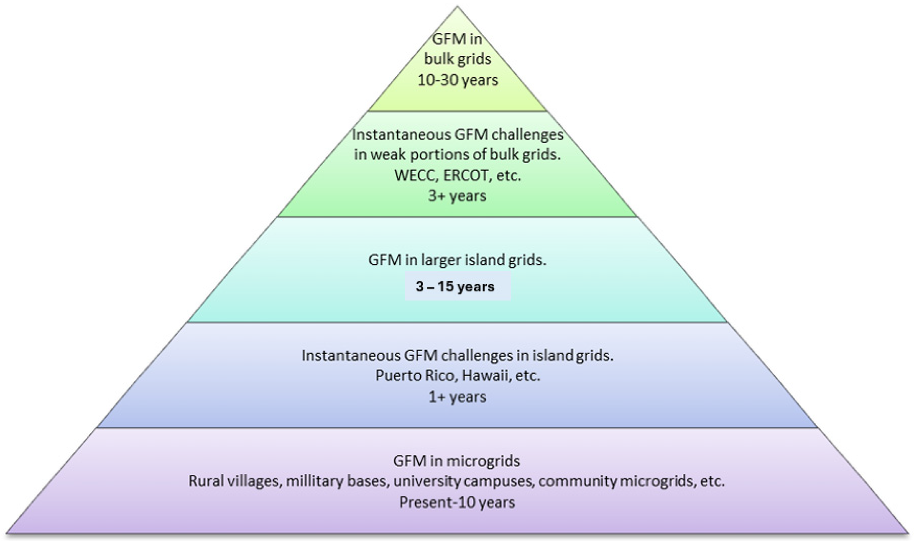
Figure 1. Integrating GFM control into the electrical grid.
Sustainability 16 02148 g001
Figure 2. Adopted self—synchronized universal droop controller (SUDC).
Sustainability 16 02148 g002
Figure 3. Schematic of six GFM inverter controllers connected in a small network.
Sustainability 16 02148 g003
Figure 4. Adoption of six GFM inverter controllers in the EMT real—time simulator tool.
Sustainability 16 02148 g004
Figure 5. The 123-bus test grid testbed [9].
Sustainability 16 02148 g005
Figure 6. Validation of six GFM inverter controllers in the on—off grid: (a) AC source real power, (b) AC source reactive power, (c) voltage, (d) frequency, (e) real power, (f) reactive power.
Sustainability 16 02148 g006
Figure 7. Black start capability of six GFM inverter controllers in grid—disconnected mode: (a) AC source real power, (b) AC source reactive power, (c) voltage, (d) frequency, (e) real power, and (f) reactive power.
Sustainability 16 02148 g007
Figure 8. Validation of six GFM inverter controllers connected in the IEEE 123 test feeder in on—off grid: (a) real power, (b) reactive power, (c) voltage, (d) AC source real and reactive powers, and (e) frequency.
Sustainability 16 02148 g008
Figure 9. Black start capability of six GFM inverter controllers in grid—disconnected mode: (a) AC source real and reactive power, (b) real power, (c) reactive power, (d) frequency, and (e) voltage.
Sustainability 16 02148 g009
Table 1. Parameter design guidelines.
ParametersValues
Voltage (V)1
ω* (angular frequency)377
IMAX (maximum current) (A)0.5
IMIN (minimum current) (A)0.033
Ke (constant)20
ω5
Kω5
Ksyn (synchronization gain)5
mi (constant)3
ni (constant)2
Apparent power (VA)1
Table 2. GFM inverter controller in a small network vs. placed in the IEEE 123-node test feeder.
AspectsSmall NetworkIEEE 123
Network sizeSmallLarge
Number of inverter controls66
Grid complexitySmall networkIEEE 123
Available generation resourcesSimpleComplex
Voltage stabilityEasy to maintainMore challenging
System protectionSimplifiedExtensive
Fault analysisEasierComprehensive
Power flow managementSimplerDemanding
Integration with existing systemsEasierComplex
System modeling and simulationDetailedExtensive
Disclaimer/Publisher’s Note: The statements, opinions and data contained in all publications are solely those of the individual author(s) and contributor(s) and not of MDPI and/or the editor(s). MDPI and/or the editor(s) disclaim responsibility for any injury to people or property resulting from any ideas, methods, instructions or products referred to in the content.