Article

Bus Voltage Stabilization of a Sustainable Photovoltaic-Fed DC Microgrid with Hybrid Energy Storage Systems

Department of Electrical and Computer Engineering, King Abdulaziz University, Jeddah 21589, Saudi Arabia
*
Author to whom correspondence should be addressed.
Sustainability 2024, 16(6), 2307; https://doi.org/10.3390/su16062307
Submission received: 17 January 2024 / Revised: 5 March 2024 / Accepted: 6 March 2024 / Published: 11 March 2024

Abstract

:
Renewable energy sources play a great role in the sustainability of natural resources and a healthy environment. Among these, solar photovoltaic (PV) systems are becoming more economically viable. However, as the utility of solar energy conversion systems is limited by the availability of sunlight, they need to be integrated with electrical energy storage systems to be more sustainable. This paper aims to improve the control performance of a hybrid energy storage system (HESS) with PV power generation as the primary power source. HESSs stabilize DC microgrid systems by compensating for demand generation mismatches. Batteries and supercapacitors are chosen as energy storage elements; batteries have a high energy density and are capable of supplying and absorbing energy over a long duration, while supercapacitors can store and deliver energy very quickly. To enhance the stability of the system, each storage element is connected to the DC bus using a bidirectional Ćuk converter, which offers high efficiency, a continuous current, and minimal switching losses. This study proposes a proportional–integral (PI) controller combined with the fast nonsingular integral terminal sliding mode control (FNITSMC) for HESSs to adjust the power balance in a DC microgrid. FNITSMC has the advantage of enhancing the system states to reach the equilibrium point of a long sliding surface with a fast convergence rate. The reference current for FNITSMC is obtained using a PI controller combined with a low-pass filter (LPF), which eliminates the peaking current spikes on the battery and diverts them towards the supercapacitor. The effectiveness of the proposed control scheme is validated through the real-time hardware-in-the-loop (HIL) simulations on Typhoon™ HIL-402 with added uncertainties, including load variations at various temperatures and irradiances.

1. Introduction

Renewable energy resources such as wind, geothermal, solar, and hydropower energy are becoming increasingly popular since they have numerous advantages, such as being pollution-free and available sustainably [1]. In 2022, there was an additional 243 GW of solar photovoltaic (PV) capacity, an increase of 25% over the previous year. This trend was followed by increases in wind power, hydropower, and other renewable energy sources of 9%, 2%, and 4%, respectively [2]. The increase in solar PV capacity is due to low operating and maintenance costs [3]. Furthermore, from the consumer’s perspective, they create benefits, with a reduction in electricity costs of around 24.7% [4].
Maximum power point tracking (MPPT) control maximizes power extraction from a solar PV capacity. As an illustration, by using the MPPT control scheme on a single 200 W Kyocera™ KC200GT solar PV, a maximum power of 192 W can be obtained with an efficiency of 96%. A facility with 60,000 similar PV modules could produce approximately 11.52 MW of peak power compared to just 8.4 MW at an efficiency of around 70% without MPPT control. With MPPT, the solar energy conversion systems have a power extraction efficiency of up to 98%. This improvement may not significantly influence a small residential capacity; however, in large PV farms, even a minor improvement will significantly alter the generated output [5].
In the DC microgrid, an energy storage system (ESS) can be introduced to store unused energy, enhance stability, and act as a buffer to suppress power oscillations. The characteristics of an ESS vary in terms of price, life cycle, power density, and energy density. To stabilize the DC bus, the system requires high-energy-density storage to compensate for low-frequency oscillations and high-power density to supply and absorb power during transients [6,7]. These characteristics can be found in a hybrid energy storage system (HESS) consisting of battery and supercapacitor banks. A battery can provide ten times more energy over a much longer duration than a supercapacitor, while a supercapacitor can deliver energy ten times faster than a battery [8,9]. On the other hand, a DC microgrid with a supercapacitor bank is likely to increase the overall costs; however, this can be compensated, as the presence of a supercapacitor can improve the system’s efficiency and the battery’s life cycle by responding instantly to sudden fluctuations and thereby reducing current stresses on the battery [10,11].
An HESS requires controlled bidirectional DC−DC converters to regulate the stability of the power balance in the DC microgrid system. Several methods have been used to control the bidirectional converters, including fuzzy logic control (FLC), droop control, proportional–integral (PI) control, model predictive control (MPC), sliding mode control (SMC), etc.
In an example system based on FLC, electric double-layer capacitor storage and a DC–DC converter is used to regulate both the stored energy balance and the output power balance. FLC is only responsible for controlling stored energy balance by regulating the DC voltage reference within ±5% of the rated value. The membership function of FLC is based on the stored energy ratio and all stored energy averages; gain scheduling maintains the DC voltage stability [12]. However, it is quite challenging to determine the appropriate fuzzy rules and membership functions [13,14].
Droop control maintains a stable DC bus voltage level on the microgrid when distributing load current [15]. However, many techniques for droop control can only accomplish proportional power sharing in the steady-state condition [16,17]. In [18], the current references are obtained by implementing virtual resistance droop (VRD) control and virtual capacitance droop (VCD) control to decouple the power of each ESS with different dynamics. VCD can regulate the supercapacitor system to respond to only fast fluctuations, while VRD handles the battery system to respond to the slow dynamics to maintain a constant power supply. Furthermore, a PI controller adjusts the power sharing using a bidirectional buck–boost converter. The results show that the DC bus voltage overshoots and undershoots due to load switching remaining within 1.85% [19,20]. This approach has a tracking reference that makes it unsuitable for nonlinear systems. Another challenge is establishing the VCD and VRD reference values; incorrect values result in inefficient power sharing and unstable DC bus voltage.
Dual-loop control strategies based on PI are commonly used for HESSs due to their simplicity and ease of implementation. A voltage control loop generates HESS current references, while the current control loop acquires the duty ratio of DC–DC converters to track the current references [21,22,23,24,25]. However, in an HESS with independent converters for each ESS, this strategy results in an inadequate current regulation for such a highly nonlinear system, resulting in ±3.5% voltage fluctuations on the DC bus. Moreover, this strategy is also unable to address the impact of the intermittent nature and uncertainties of renewable resources completely [26].
To address the above-mentioned weaknesses of the dual-loop PI control, MPC is introduced to predict the total required current distribution for the battery and supercapacitor to stabilize the DC bus [27]. The current distribution for each storage element is determined by considering specified constraints, including the maximum and minimum limits on the battery’s state of charge, battery current, supercapacitor voltage, and supercapacitor current. MPC then predicts the modulation index for the battery and supercapacitor, where each modulation index drives a pulse width modulation (PWM) generator for the storage converter. Another approach based on MPC uses a modified cost function to reduce the DC bus voltage variations. The results show that the DC bus voltage can follow its reference with an overshoot of around 1%. However, appropriate decoupling between current components is not achieved in such MPC algorithms since the cost function weights are not well optimized under varied operating situations. Furthermore, the performance of this system is determined by the system parameter uncertainties and the model accuracy [28]. To address the modeling uncertainties, some techniques based on MPC with real-time parameter identification and adaptive MPC are proposed [29,30]. However, all MPC-based schemes are excessively complex.
SMC has been widely used to handle the modeling uncertainties in the systems due to its robustness [31,32,33,34]. PI and SMC have been integrated to ensure the proper voltage level on the common DC bus. PI control with a low-pass filter (LPF) is used to split up the reference current into references for the battery and supercapacitor. SMC finally controls the current sharing. The results indicate that the DC bus voltage can follow its reference with an overshoot of around 3.8% and a settling time of around 0.45 s [35,36]. The use of standard SMC, however, does show its drawbacks of chattering and uncertain convergence time.
The control strategies, power-sharing control with HESSs, and bus voltage stabilization in DC microgrids discussed above are summarized in Table 1.
The table shows numerous benefits and limitations of the PI-SMC-based approach. Chattering issues in SMC can be mitigated by using a sliding surface with a boundary layer. Furthermore, convergence can be accelerated and guaranteed by modifying the sliding surface in certain ways.
The fast nonsingular integral terminal sliding mode control (FNITSMC) can overcome these shortcomings of the standard SMC. It is also simpler to implement and demonstrates higher robustness to external disturbances and parametric uncertainties resulting from unmodeled loads and changes in plant dynamics. Therefore, it can reduce overshoot/undershoot and statistical errors. In addition, it also guarantees finite-time convergence by accelerating the rise time and settling time, along with high tracking accuracy [37,38].
Regarding the converter technologies, most of the published works utilize the bidirectional DC–DC buck–boost converters to regulate the DC bus [11,19,20]. However, the bidirectional buck–boost converter has the disadvantages of poor transient responsiveness, large peak currents in power components, intermittent input currents, etc. These weaknesses can be overcome by employing the bidirectional DC–DC Ćuk converter, which has the benefits of high efficiency, minimal switching losses, and better output current characteristics [39,40,41].
This article proposes a control strategy combining PI control with FNITSMC to control the DC bus voltage stability for the HESS consisting of a battery energy storage system (BESS) and a supercapacitor energy storage system (SESS). The proposed strategy is outlined as follows:
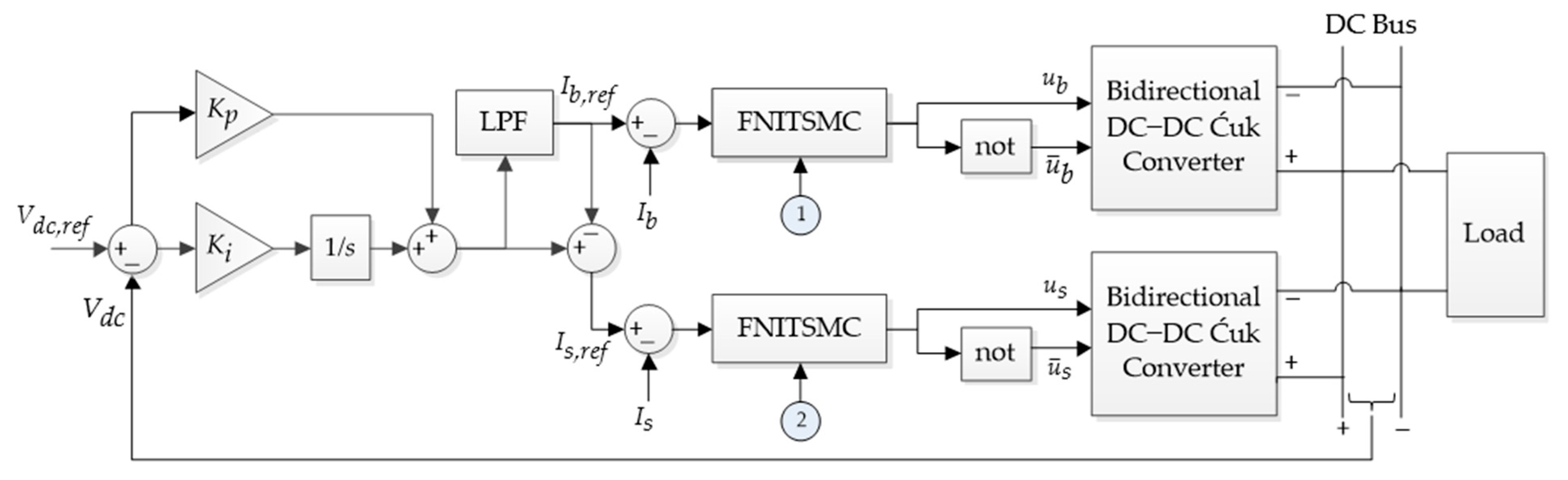
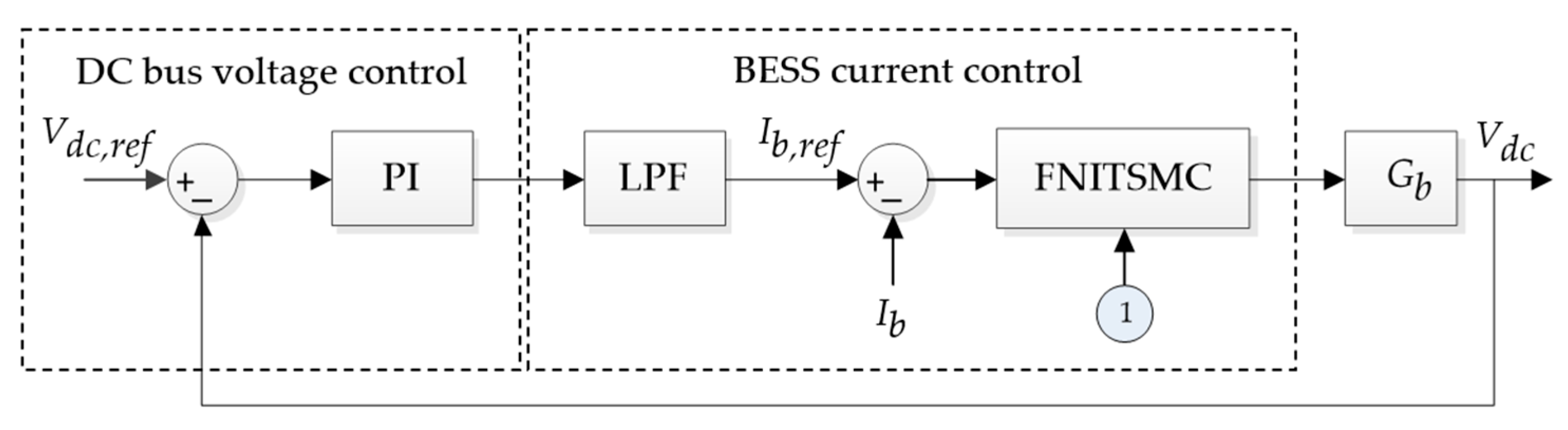
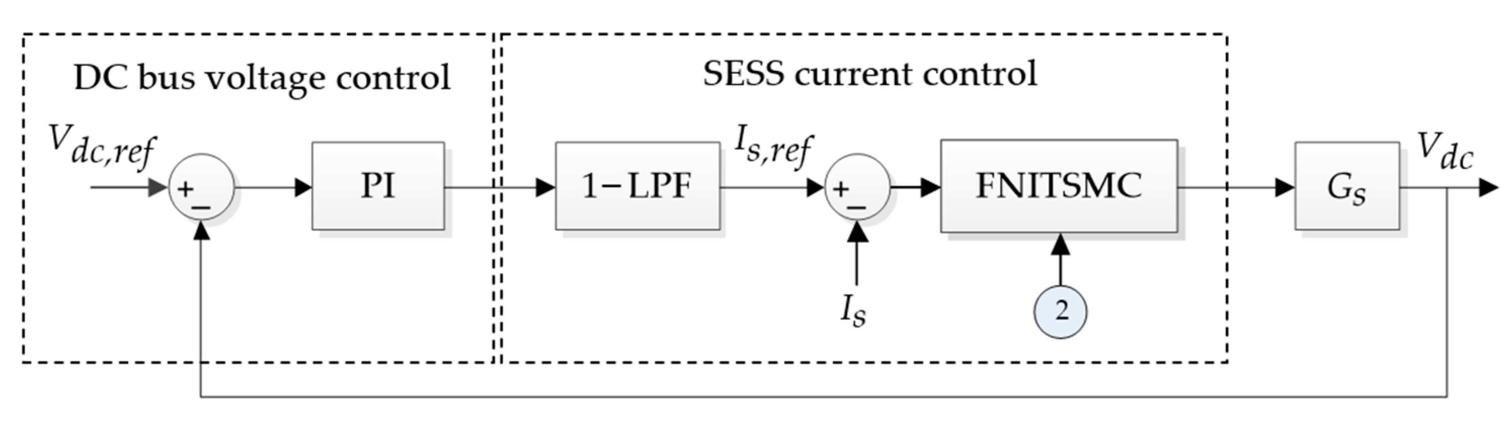
  • The PI controls the DC bus voltage and generates a total current reference for the HESS. Using an LPF, the total current is split up into low- and high-frequency components serving as references for BESS and SESS, respectively.
  • FNITSMC adjusts the PWM of the bidirectional Ćuk converters for the BESS and SESS to control the power balance of the DC microgrid. The BESS compensates for the steady-state power demands, whereas the SESS compensates for the transient ones.
This proposed controller aims to improve the control performance of an HESS with PV power generation as its primary source, with added uncertainties including load variations at varying temperatures and irradiance levels. The performance metrics will be the transient parameters like rise time, settling time, percentage overshoot, and statistical tracking errors. The accelerated rise time and settling time will demonstrate the fast convergence.
Hardware-in-the-loop (HIL) simulations are performed on the Typhoon™ HIL-402 system to validate the effectiveness of the proposed scheme and its performance in maintaining the DC bus stability. The proposed methodology has shown improved performance over the PI-SMC approach tested on such systems. The integral absolute error (IAE) of the DC bus voltage is reduced by more than 35% compared to the PI-SMC-based power-sharing method. The approach is also more robust to load variations and external disturbances as evidenced by low voltage fluctuations and overshoots/undershoots compared to PI-SMC.
The following are the main contributions of this paper:
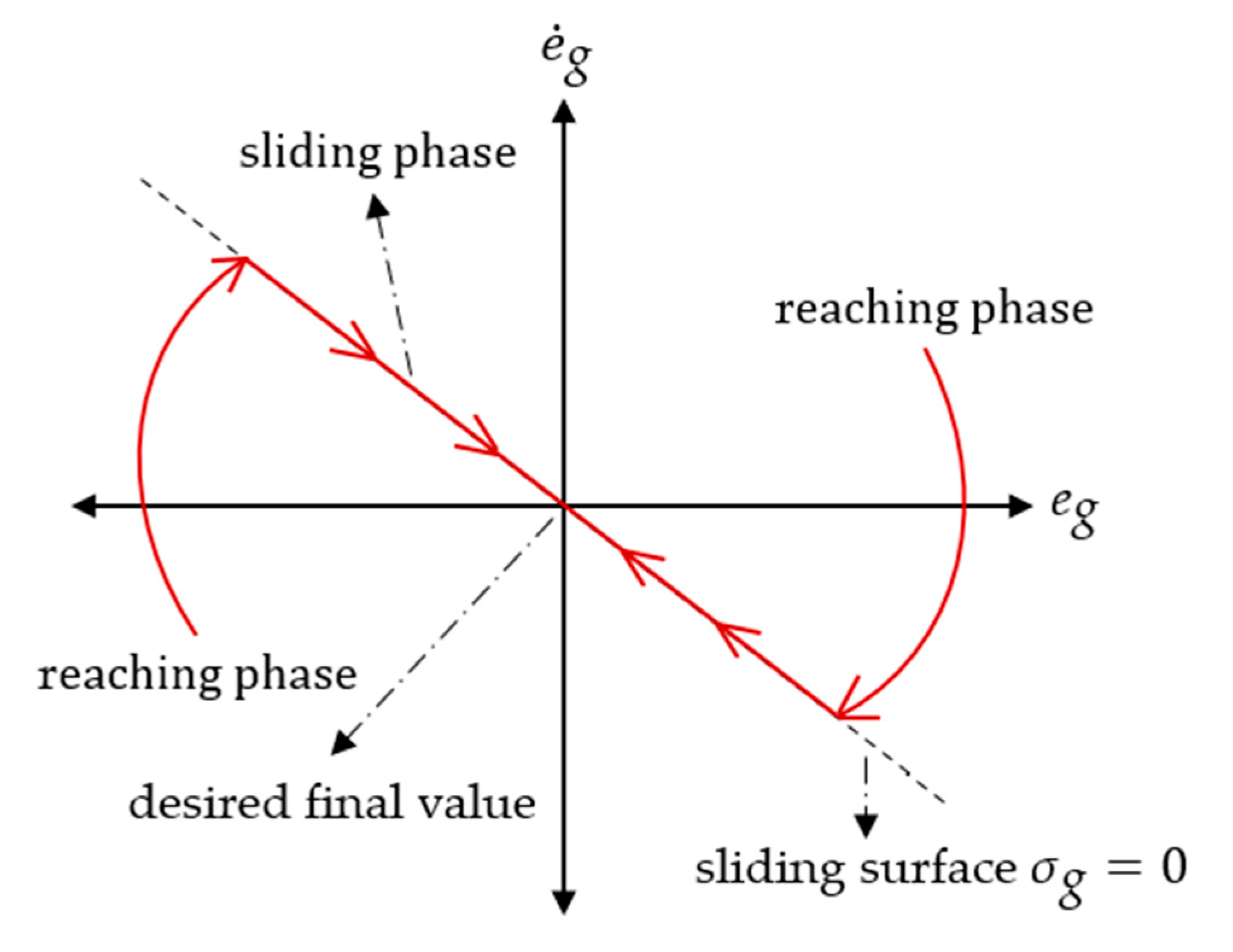
  • The design of FNITSMC with a modified nonlinear sliding surface that helps the system states achieve faster convergence to the equilibrium.
  • The design of a PI-FNITSMC-based current sharing controller for HESSs using bidirectional DC–DC Ćuk converters with improved performance characteristics, good stability (transient performance), faster and more precise tracking, and robustness to uncertainties and disturbances.
  • Verification of the performance of the proposed controller with load, temperature, and irradiance variations using the Typhoon™ HIL-402 system.
The remaining sections of this article are organized as illustrated in Figure 1. Section 2 presents the modeling of the PV system and HESS. Section 3 gives the design of the MPPT controller based on the global sliding mode control (GSMC). Section 4 gives the complete design of the proposed voltage and current control with the HESS. Section 5 explains the system configuration used in simulations. Stability analysis is carried out for load and input duty cycle variations. Rigorous HIL simulations are then performed, and results are discussed and analyzed. Conclusions are then drawn in Section 6.

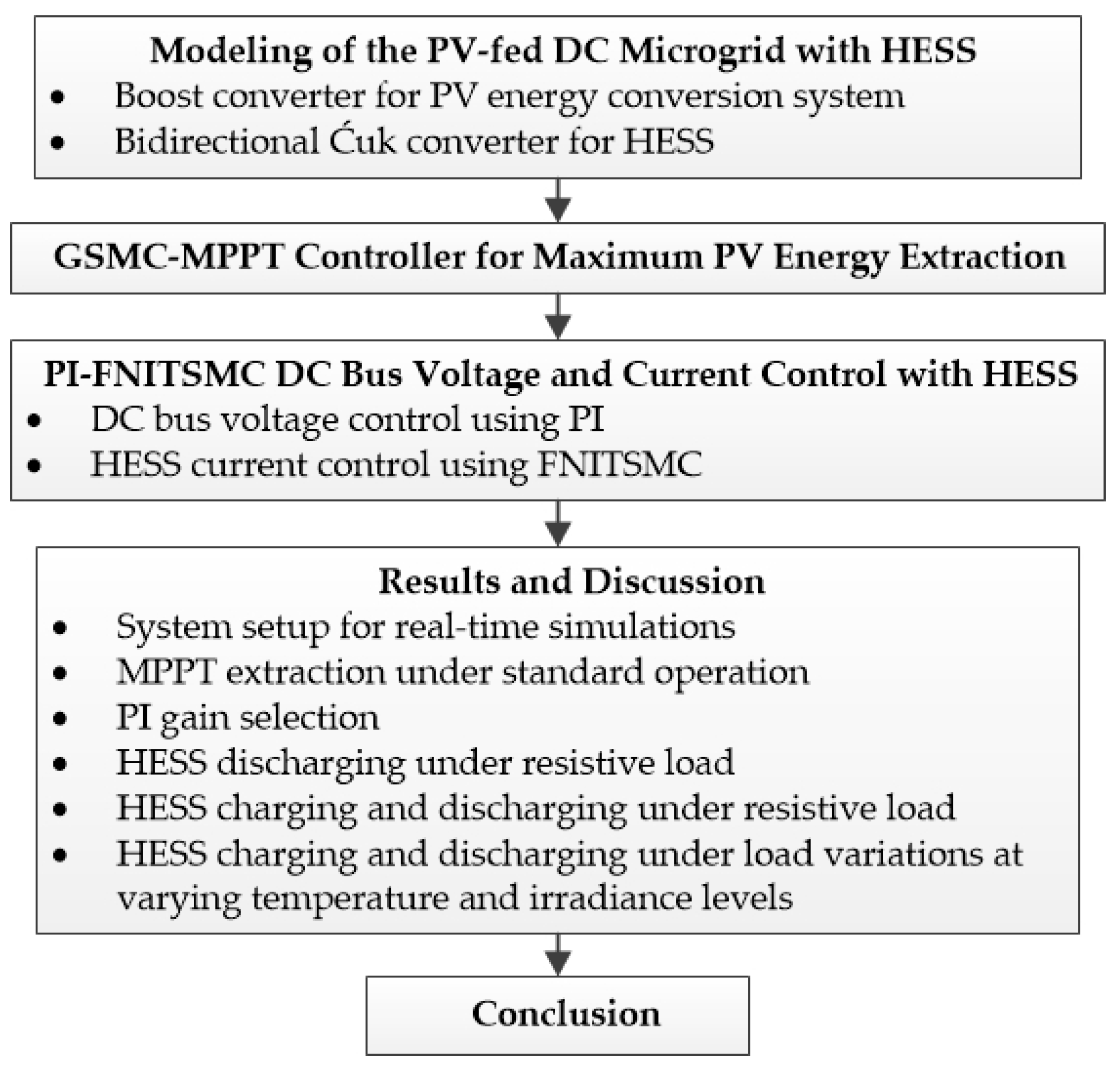
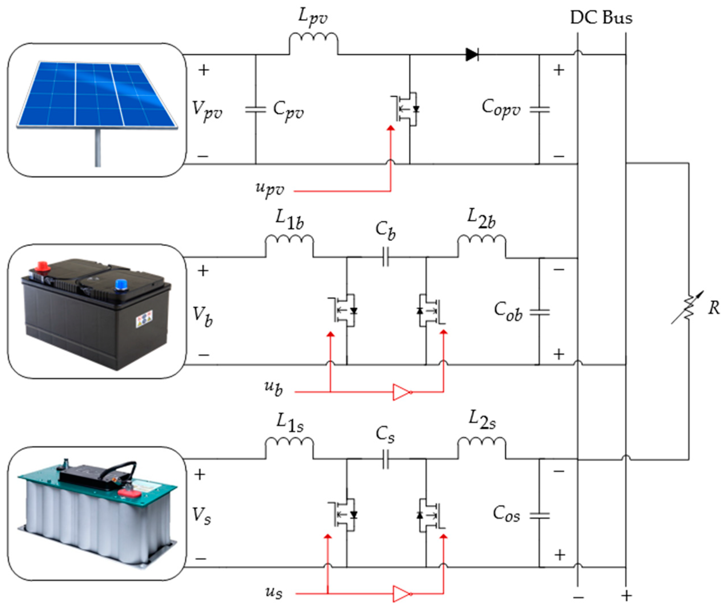
2. Modeling of the PV-Fed DC Microgrid with HESS

This paper investigates a DC microgrid with the configuration shown in Figure 2. The system comprises a PV array, a battery bank, and a supercapacitor bank connected to the DC bus via different DC–DC converters. The PV array is connected to the DC bus via an MPPT boost converter that prevents power flow in the opposite direction. In contrast, the HESS storage elements—the battery and the supercapacitor—are connected to the DC bus through bidirectional Ćuk converters to regulate the power flow in both directions, charging and discharging. The bidirectional Ćuk converters maintain the DC bus’s stability by regulating power sharing to meet the load demands. The stability of the DC bus during transient and steady state will be regulated by the SESS and BESS, respectively.

2.1. Boost Converter for PV Energy Conversion System

The DC–DC boost converter regulates the PV output voltage ( V pv ) to extract the maximum power. Equation (1) gives the dynamic characteristics of a PV-fed boost converter [42] with the system parameters shown in Table 2.
I ˙ L pv V ˙ pv = 0 1 L pv 1 C pv 0 I L pv V pv + V dc L pv 0 d pv + V dc L pv 0 I pv C pv 0 1 0
where I L pv ,   V pv ,   L pv , V dc , C pv , I pv , and d pv represent the inductor current, the output voltage of the PV, the inductor’s inductance, the DC bus voltage, the capacitor’s capacitance, the PV current, and the duty ratio of the converter, respectively. V ˙ pv in Equation (1) only works if the capacitor voltage ripple is negligible, the inductor current is always continuous, and the time steps are significantly larger than the converter switching frequency. The performance of the boost converter can drastically deteriorate due to PWM switching noise introduced into the data obtained from the voltage and current sensors. Nevertheless, it is important to note that when the system is in operation, its primary function is to charge a battery or supercapacitor bank. This charging process has the benefit of minimizing noise disturbances, as these loads serve as substantial LPFs, effectively attenuating high-frequency noises. Furthermore, the performance of the proposed controller in terms of transient response is expected to have the ability to effectively mitigate low-frequency noise and interference, thereby enabling the quick regain of MPPT.

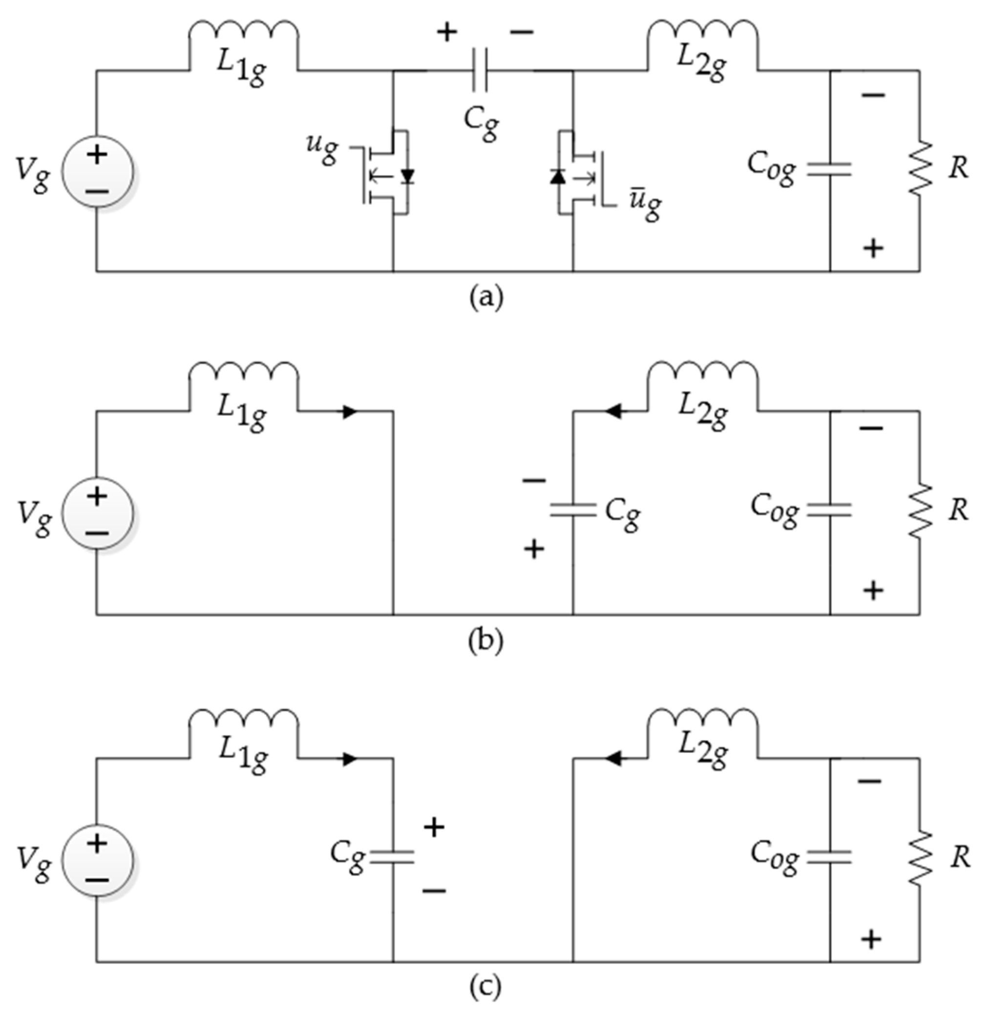
2.2. Bidirectional Ćuk Converter for HESS

The BESS shown in Figure 2 consists of a bidirectional Ćuk converter. The controller regulates the battery’s charge and discharges to stabilize the power balance. The current, I C ob , in the capacitor, C ob , can be negative, positive, or null. When I C ob is greater than 0, it indicates a discharge mode; when it is less than 0, it indicates a charge mode; and when it is null, it indicates a standby mode. The configuration of the SESS is also identical to that of the BESS, with C os as the output capacitor. The other components in both subsystems are shown in Figure 2. As both the BESS and SESS are identical, all the parameters are given a subscript, g , where g b for the BESS and g s for the SESS.
The BESS and SESS state–space model is derived through an analysis of the bidirectional Ćuk converter dynamics, as depicted in Figure 3. The parameters in shown in the figure are given in Table 2.
When the MOSFET is turned on with PWM input, u g , the inductor voltages are
V L 1 g = V g = L 1 g di L 1 g dt   ,
V L 2 g = V C g V C og = L 2 g di L 2 g dt   .
and the capacitor currents are
I C g = I L 2 g = C g dv C g dt   ,
I C og = I L 2 g V C og R = C og dv C og dt .
Rewriting Equations (2)–(5) in the state space form x ˙ g = A 1 g x g + B 1 g V g is as follows:
I ˙ L 1 g I ˙ L 2 g V ˙ C g V ˙ C og = 0 0 0 0 0 0 1 L 2 g 1 L 2 g 0 1 C g 0 0 0 1 C og 0 1 R C og I L 1 g I L 2 g V C g V C og + 1 L 1 g 0 0 0 V g   .
When the MOSFET is turned off, the inductor voltages are
V L 1 g = V g V C g = L 1 g di L 1 g dt   ,
V L 2 g = V C og = L 2 g di L 2 g dt   ,
and the capacitor currents are
I C g = I L 1 g = C g dv C g dt   ,
I C og = I L 2 g V C og R = C og dv C og dt   .
Rewriting Equations (7)–(10) in state space form x ˙ g = A 2 g x g + B 2 g V g is as follows:
I ˙ L 1 g I ˙ L 2 g V ˙ C g V ˙ C og = 0 0 1 L 1 g 0 0 0 0 1 L 2 g 1 C g 0 0 0 0 1 C og 0 1 R C og I L 1 g I L 2 g V C g V C og + 1 L 1 g 0 0 0 V g   .
If d g is the duty ratio of the PWM input and d g = 1 d g , then the matrices are
A g = A 1 g d g + A 2 g d g B g = B 1 g d g + B 2 g d g   .
Combining Equations (6) and (11) using definition (12) generates the average state space model, x ˙ g = A g x g + B g V g , as follows [45,46]:
I ˙ L 1 g I ˙ L 2 g V ˙ C g V ˙ C og = 0 0 d g L 1 g 0 0 0 d g L 2 g 1 L 2 g d g C g d g C g 0 0 0 1 C og 0 1 R C og I L 1 g I L 2 g V C g V C og + 1 L 1 g 0 0 0 V g   .

3. GSMC-MPPT Controller for Maximum PV Energy Extraction

The proposed PV system utilizes a GSMC-based MPPT control technique, which incorporates a two-stage controller, as described in [42]. The first stage calculates the maximum power point (MPP) reference based on the current values of temperature ( T ) and irradiance ( E ), while GSMC in the second stage adjusts the PWM of the boost converter to force the PV system to operate at the MPP for the best performance, as shown in Figure 4.
Figure 4. Block diagram of PV control strategy. ① represents the variables used in MPP seeking, which are N s , A , K , q , I ph , I rs , while ② represents the variables used in GSMC for the PV systems, which are C pv , L pv , α pv , G pv , η , I pv , σ pv .
Sustainability 16 02307 g004
The PV reference voltage is calculated as [47]
V pv , ref = N s AKT q · log I ph 0.909   I ph + I rs I rs
where N s is the number of PV cells connected in series in a panel; K = 1.3805 × 10 23   J / K is the Boltzmann’s constant; A is the P-N junction characteristic factor; T is the temperature of the cell; I rs is the reverse saturation current; q = 1.6022   ×   10 19 C is the electron charge; and I ph is the photocurrent. I ph is related to cell temperature and solar radiation as follows:
I ph = I s h + k is T 298 E 1000
where I sh is the short-circuit current of the PV cell; k is is the short-circuit current temperature coefficient. I rs in Equation (13) is as follows:
I rs = I s h exp q V oc N s AKT 1 1 T 298 3 exp q E go AK 1 298 1 T
where V oc is the open-circuit voltage and E go represent the band-gap energy.
The following explains the procedure of designing a controller for a PV system, which consists of an equivalent and a switching control. Before obtaining an equivalent controller, the sliding surface must be determined. The sliding surface of GSMC is defined as
σ pv x , t = β pv e pv t + α pv e ˙ pv t F t exp η t
where β pv ,   α pv , and η are positive constants, e pv t is the tracking error of V pv , and F ( t ) is designed to achieve the global sliding surface by fulfilling three conditions:
F ( 0 ) β pv e pv ( 0 )
F ( t ) 0   as   t
F ( t )   is differentiable
Condition (18a) represents the initial states of the sliding surface, (18b) the asymptotic stability, and (18c) the existence of the sliding mode. Then, the equivalent control is derived by differentiating the sliding surface of Equation (17):
σ ˙ pv x , t = β pv e ˙ pv t + α pv e ¨ pv   t F ˙ 0 exp η t   .
Substituting e ¨ pv t = V ¨ pv , ref   t V ¨ pv t ,
σ ˙ pv x , t = β pv e ˙ pv t + α pv V ¨ pv , ref   t α pv V ¨ pv t F ˙ 0 exp η t   .
Differentiating V ˙ pv from Equation (1) to obtain V ¨ pv and substituting in Equation (20) yields
σ ˙ pv x , t = β pv e ˙ pv t + α pv V ¨ pv , ref   t α pv I ˙ L pv C pv + I ˙ pv C pv t F ˙ 0 exp η t   .
Substituting I ˙ L pv from Equation (1) into Equation (21) yields
σ ˙ pv x , t = β pv e ˙ pv t + α pv V ¨ pv , ref   t α pv C pv V pv L pv + V dc L pv V dc L pv u pv , eq + I ˙ pv t F ˙ 0 exp η t   .
Making σ ˙ pv x , t = 0 to obtain the equivalent control is as follows:
u pv , eq = C pv L pv α pv V dc β pv e ˙ pv t + α pv V ¨ pv , ref   t α pv C pv V pv L pv + V dc L pv + I ˙ pv t F ˙ 0 exp η t   .
The signum function sgn ( · ) is widely used to enforce the sliding mode operation over a given manifold. In this article, the sgn ( · ) function is replaced with the saturation function, sat ( · ) , to enforce a boundary condition to solve the accompanying chattering issue. The saturation function is given below:
sat ( σ pv ) =   1     ;       σ pv > Δ                     σ pv / Δ   ;   σ pv Δ 1     ;       σ pv < Δ    
where Δ is the boundary layer for chattering reduction, linear feedback control inside the boundary layer, and switching control outside it [48,49]. The switching control with reduced chattering is designed as follows:
u pv , sw = G pv   sat σ pv
where G pv is a variable gain (generally high) of the switching control.
Combining Equations (23) and (25), the GSMC with equivalent and switching controls, u pv = u pv , eq + u pv , sw , for a PV system can be given as follows:
u pv = C pv L pv α pv V dc β pv e ˙ pv t + α pv V ¨ pv , ref t α pv C pv V pv L pv + V dc L pv + I ˙ pv t F ˙ 0 exp η t G pv   sat σ pv .

4. PI-FNITSMC DC Bus Voltage and Current Control with HESS

In this article, power distribution is realized using FNITSMC based on PI and LPF, as illustrated in Figure 5. PI combined with LPF aims to split the power demand into steady-state and transient power. The PI controller produces a total current reference for the HESS and then uses LPF to generate a low-frequency current reference for the BESS. The high-frequency current reference for the SESS is then obtained by subtracting the BESS current reference from the PI output. The current references can be positive, negative, and null values; a positive current indicates the discharge mode, negative the charge mode, and null the stand-by mode. After obtaining the reference current, the FNITSMC will control the BESS and SESS to follow its reference. The FNITSMC technique offers robust benefits in maintaining power balance in the DC bus through the charging and discharging of the BESS and SESS.
Figure 5. Block diagram of HESS control strategy. ① represents the variables of FNITSMC for the BESS, which are L 2 b , V C b , α b , β b , γ b , k b , l b , V dc , I ˙ ob ,   G b , and sat ( σ b ). Furthermore, ② represents the variables of FNITSMC for the SESS, which are L 2 s , V c s , α s , β s , γ s , k s , l s , V dc , I ˙ os , G s , and sat ( σ s ).
Sustainability 16 02307 g005

4.1. DC Bus Voltage Control Using PI

The reference current ( I g , ref ) in the HESS is derived from the DC bus voltage error ( V dc , ref V dc ) in the PI-based voltage control loop, as illustrated in Figure 5. Acquiring the correct PI gains necessitates the execution of multiple phases, obtaining the voltage transfer function of the converter and then adjusting the PI parameters based on different analyses. The transfer function of the bidirectional Ćuk converter can be obtained as Equation (27) and takes the form of Equation (28). This model is identical to the one generated through Leverrier’s method [50].
G g , ess = V C og V g = C g ( sI A g ) 1 B g   ,
T s = d g d g L 1 g L 2 g C g C og s 4 + 1 R C og s 3 + d g 2 L 2 g C g + d g 2 L 1 g C g + 1 L 2 g C og s 2 + d g 2 L 2 g C g R C og + d g 2 C g L 1 g R C og s + d g 2 L 1 g L 2 g C g C og   .
In this work, MATLAB™ (https://ww2.mathworks.cn/products/matlab.html, accessed on 4 March 2024) PID tuning tools are used to obtain the PI gains.

4.2. HESS Current Control Using FNITSMC

FNITSMC stabilizes the DC microgrid by supplying the correct PWM value to the bidirectional Ćuk converters in each ESS. FNITSMC is an SMC enhancement that allows the state to converge to an equilibrium point speedily and precisely in finite time by implementing the integral and nonlinear terms in the sliding surface. The integral term is designed to be dominant when the system state is far from the equilibrium point, which ensures a faster convergence speed. When the state is close to the equilibrium point, the nonlinear term becomes dominant and guarantees convergence in finite time [36].
Both standard SMC and FNITSMC designs include two steps. The initial stage is to design the equivalent control based on the sliding surface followed by the second stage, which is a switching control to drive the state trajectory of the plant to the sliding surface. Figure 6 illustrates the different phases in the SMC.
FNITSMC requires reference currents for both the BESS and SESS to track current errors and regulate the power balance of the DC microgrid system. The reference currents in the HESS are obtained using a PI controller combined with an LPF, which divides the overall current into low- and high-frequency components. To reduce system latency, 31 rad/s is chosen as the LPF cut-off so that the battery current responds to changes happening in more than 0.2 s [21,51,52].
After obtaining the reference current for an ESS, the sliding surface is designed. The modified sliding surface of FNITSMC for an ESS with a fast convergence rate is defined as
σ g t = 0 t e g τ d τ + β g 0 t e g τ d τ k g + α g e g t l g sgn ( e g ) γ g I C og t
where e g ( t ) is the current tracking error; α g ,   β g ,   γ g > 0 ; k g > 0 ; and 1 < l g < 2 , with the condition of k g > l g [37]. When the states are far from the equilibrium point, β g 0 t e g τ d τ k g will dominate α g e g t l g   sgn ( e g ) , which will ensure a faster convergence. However, when the system states are close to the equilibrium point, the α g e g t l g   sgn ( e g ) will play the dominant role, which guarantees the convergence in finite time.
When the sliding surface σ g = 0 , then the sliding motion can be defined as
σ ˙ g ( t ) = e g t + β g e g k g 0 t e g τ d τ ( k g 1 ) + α g e ˙ g l g e g t ( l g 1 ) sgn ( e g ) γ g I ˙ C og t .
The u g , eq of FNITSMC is obtained by eliminating the sgn ( e g ) in Equation (30) to avoid chattering; substituting I ˙ C og t = I ˙ L 2 g t I ˙ og t in Equation (30); and then substituting I ˙ L 2 g t from Equation (13), yielding
u g , eq = L 2 g γ g V c g e g t + β g e g k g 0 t e g τ d τ ( k g 1 ) + α g e ˙ g l g e g t ( l g 1 ) + γ g V C og t L 2 g + γ g I ˙ og t .
Moreover, u g , sw is designed as
u g , sw = G g sat σ g .
Finally, the FNITSMC consisting of both the equivalent and the switching controls, u g = u g , eq + u g , sw , can be written as
u g = L 2 g γ g V c g e g t + β g e g k g 0 t e g τ d τ ( k g 1 ) + α g e ˙ g l g e g t ( l g 1 ) + γ g V C og t L 2 g + γ g I ˙ og t G g sat σ g .

5. Results and Discussion

To verify the effectiveness of the proposed power-sharing control schemes for the microgrid system consisting of a PV input and an HESS, and demonstrate its superiority to the conventional control schemes, a comparative HIL real-time simulation study is conducted utilizing the Typhoon™ HIL-402 platform.
The following steps are required to acquire real-time simulation data:
  • A DC microgrid consisting of a PV system, an HESS, and load is designed using the Typhoon™ HIL Control Center software V2023.2.
  • Similarly, the MPPT controller based on GSMC and PI-FNITSMCs for both the BESS and SESS are also designed using the Typhoon™ HIL Control Center software V2023.2.
  • A complete simulation model is compiled and uploaded to the Typhoon™ HIL-402.
  • Simulation parameters like sampling time and execution time are also set. The sampling time is set in a way that the achieved results are close to the real time. For example, an execution of the system for 24 s took almost 33 s at 200 ksps to achieve the best possible results. This total time included the overhead of data gathering and transportation to the main personal computer (PC).
  • The real-time simulations are conducted, and the results are communicated back to the PC after the completion of each simulation.
  • The results are plotted in Matlab™ to make it easier for further processing and displaying specific information.
To evaluate the robustness of the proposed control scheme, the impact of load variations in both charging and discharging states, as well as at varying temperatures and irradiances, is discussed.

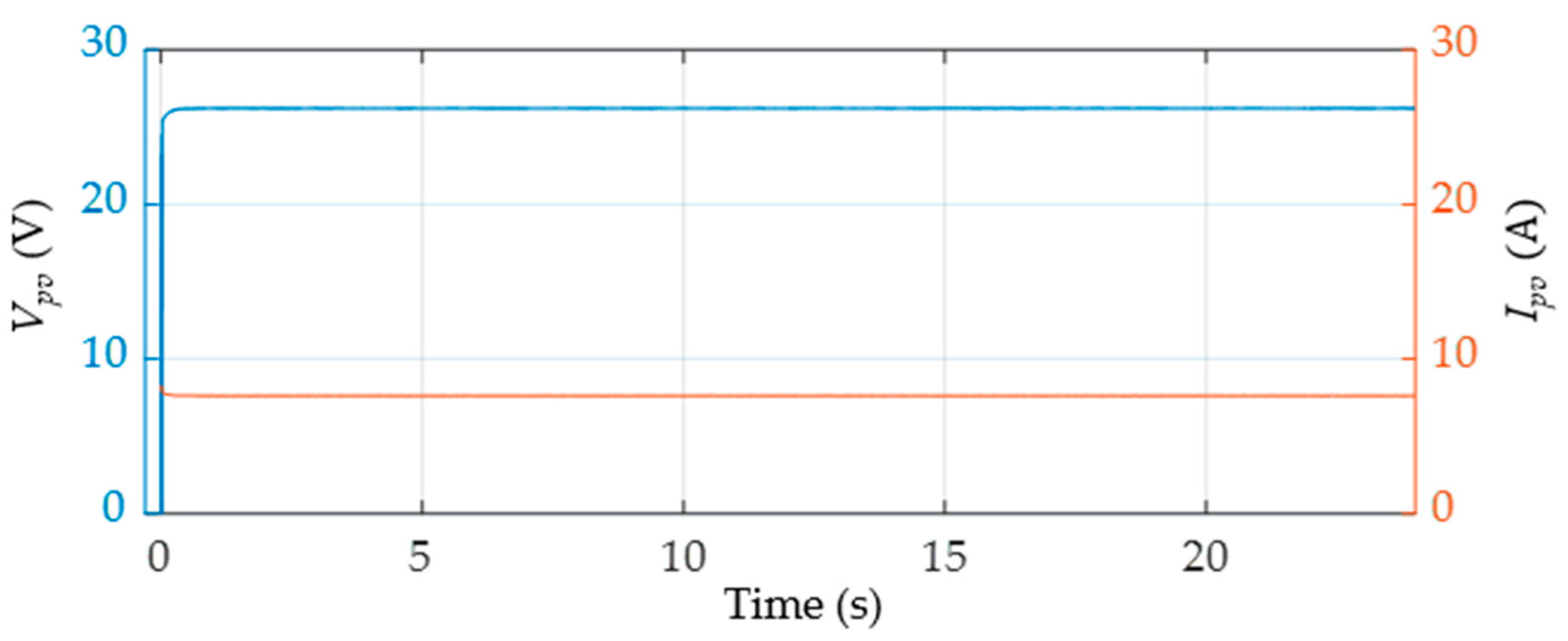
5.1. MPPT Power Extraction under Standard Operating Conditions

To verify that the MPPT algorithm works effectively, the PV system must be tested before being connected to the HESS. The simulations are performed at a temperature of 25 °C, with an irradiation level of 1000 W/m2 and a load resistance of 21 Ω. Figure 7 and Figure 8 depict the output response of a PV system without being connected to an HESS, which includes V pv , I pv , and P pv with values of 26.3 V, 7.6 A, and 200 W, respectively. The V pv , I pv , and P pv values perfectly match the rated voltage in the PV panel specifications of a single Kyocera™ KC200GH-2P module, which indicates that the MPPT technique can extract maximum power effectively.

5.2. PI Gain Selection

This paper investigates three cases of bus voltage stabilization: discharging only, and charging and discharging without and with varying temperature and irradiance. All of these cases are tested with varying loads: 15 Ω, 21 Ω, and 100 Ω. The transfer function of the non-isolated bidirectional Ćuk converter derived in Equation (26) with the system parameters given in Table 2 and assuming all the parasitic resistances as 0 Ω is as follows:
G g = d g d g 8.19   ×   10 16 s 4 + 1 R ( 10   ×   10 6 ) s 3 + d g 2 1.3   ×   10 8 + d g 2 6.3   ×   10 8 + 1 1.3   ×   10 8 s 2 + d g 2 R ( 1.3   ×   10 13 ) + d g 2 R ( 6.3   ×   10 13 ) s + d g 2 8.19   ×   10 16   .
The root loci with load resistances of 15 Ω, 21 Ω, and 100 Ω and a duty cycle of d g = 0.1 0.9 are shown in Figure 9, Figure 10 and Figure 11. As the system’s closed-loop behavior is heavily dependent on both the duty cycle ( d g ) of the PWM input and the load ( R ), it is important to analyze the stability conditions. These figures show the root loci of the bidirectional Ćuk converter with varying duty cycle ( d g ) for loads of 15 Ω, 21 Ω, and 100 Ω, respectively. These sets of plots allow us to know the range of the control gain ( K g ). The system is the least closed-loop stable for d g = 0.1 ; the dominant poles remain stable for 0   <   K g   <   0.5 . In other words, at low values of d g , the control gain must be kept low or else the system will become unstable.
Neglecting circuit losses, the Ćuk converter’s nominal duty cycles with V b = 24   V ,   V s = 32   V , and V dc = 48   V are calculated as [53,54]
d b = V dc V dc + V b = 48 48 + 24 = 0.68 d s = V dc V dc + V s = 48 48 + 32 = 0.6
As these values are quite close, taking d g = d b = d s = 0.6 , the transfer functions of the two converters are similar and will simplify the overall model. The transfer functions of the bidirectional Ćuk converter with load resistances of 15 Ω, 21 Ω, and 100 Ω at d g = 0.6 are given in Equations (36)–(38), respectively.
G g = 2.9304   × 10 14 s 4 + 6 . 6667   × 10 3 s 3 + 1.0716   × 10 8 s 2 +   2.0155 × 10 11 s +   1.9536 × 10 14   .
G g = 2.9304 × 10 14 s 4 + 4 . 7619   × 10 3 s 3 + 1.0716   × 10 8 s 2 + 1.4396   × 10 11 s +   1.9536 × 10 14   .
G g = 2.9304   × 10 14 s 4 + 1000 s 3 +   1 . 0716   × 10 8 s 2 + 3.0232   × 10 10 s + 1.9536   × 10 14   .
Splitting up the control system given in Figure 5 for the BESS and SESS, the individual double loop controls, comprising outer voltage loops and inner current loops, are illustrated in Figure 12 and Figure 13. The outer voltage loop is a PI control that regulates the DC bus voltage; cascaded with the LPF, it then generates the current references for the HESS. The LPF separates the low- and high-frequency current references for the BESS and SESS, respectively. In the inner loop, FNITSMC controls the current of the respective ESS to regulate the power balance of the DC microgrid.
The PI compensation transfer function is
C ( s ) = K p s + K i s   ,
and the first-order LPF transfer function is
H ( s ) = ω c s + ω c   ,
where ω c is the filter’s cut-off frequency, which is set as 31 rad/s. However, as the LPF is used to split up the current reference, its behavior is not included in the simulations because the inner current loop is designed to be fast enough to assume a gain of 1 [18,55]. Using MATLAB™’s PID tuning tool, the PI gains for an acceptably stable set of closed-loop dominant poles are obtained as K p = 1.2 and K i = 180 . The closed-loop transfer functions of the system with the PI compensation and loads of 15 Ω, 21 Ω, and 100 Ω are given in Equations (41)–(43), respectively.
T ( s )   = 3.516 × 10 14 s +   5.275 × 10 16 s 5 +   6667 s 4 + 1.072   × 10 8 s 3 + 2.016   × 10 11 s 2 +   5.47 × 10 14 s +   5.275 × 10 16     .
T ( s )   = 3.516 × 10 14 s +   5.275 × 10 16 s 5 + 4762 s 4 + 1.072   × 10 8 s 3 + 1.44   × 10 11 s 2 +   5.47 × 10 14 s +   5.275 × 10 16   .
T ( s )   = 3.516 × 10 14 s +   5.275 × 10 16 s 5 + 1000 s 4 + 1.072   × 10 8 s 3 + 3.023   × 10 10 s 2 +   5.47 × 10 14 s +   5.275 × 10 16   .
The rise and settling times of the closed-loop system are given in Table 3.

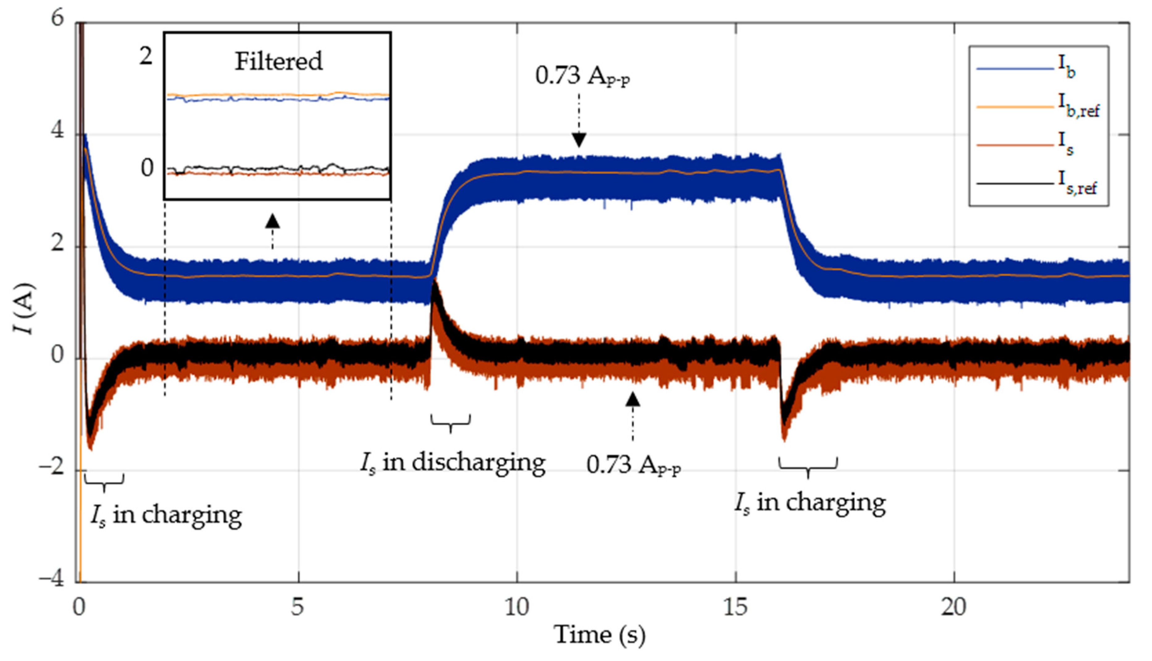
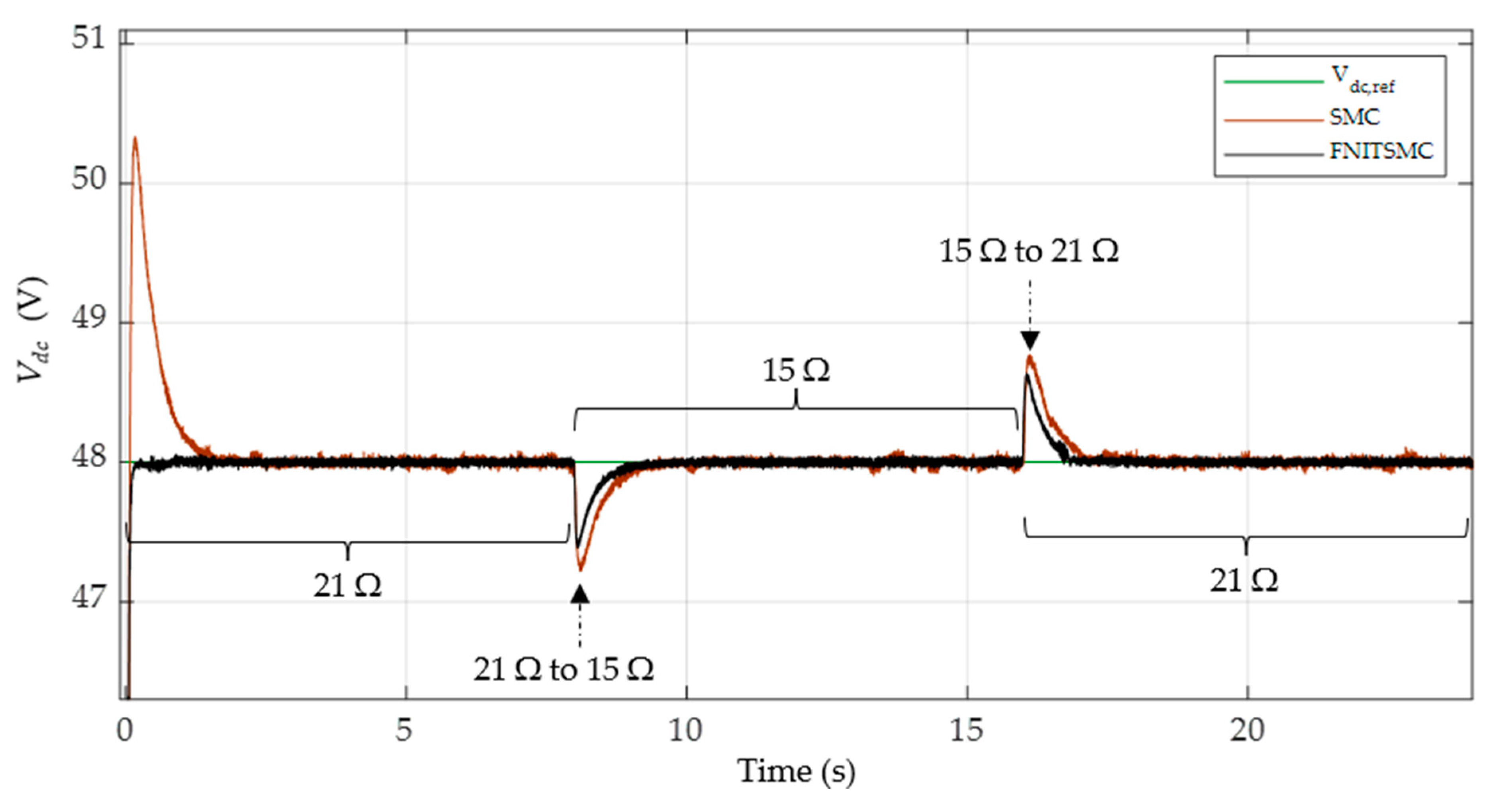
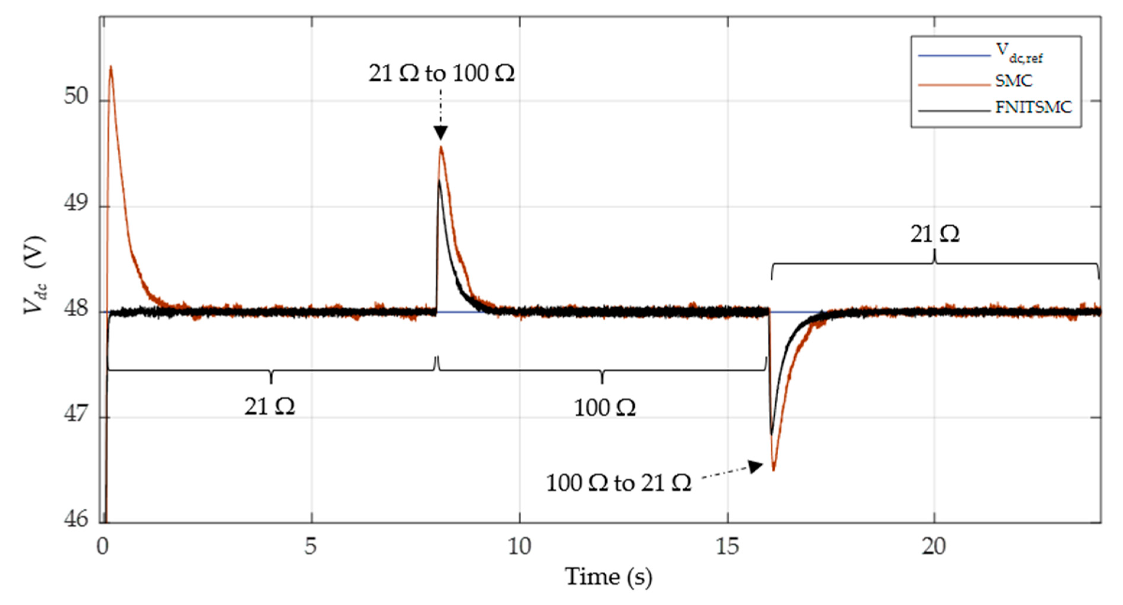
5.3. Case 1: HESS Discharging under Resistive Load

The real-time simulations of the DC microgrid employing Typhoon™ HIL-402 are conducted at 30 °C, an irradiation level of 400 W/m2, and varying load resistance. Figure 14, Figure 15 and Figure 16 show the effects of load changes on DC bus voltage and currents for the BESS and SESS. In case 1, the load is varied as follows: 21 Ω for 0–8 s, 15 Ω for 8–16 s, and again at 21 Ω for 16–24 s.
In this case, the PV system can only produce a power of around 80 W, whereas the 15 Ω load and 21 Ω loads will dissipate 153.6 W and 109.71 W at 48 V, respectively. Consequently, the battery will discharge in a steady state to compensate for the power deficit, while the supercapacitor will charge or discharge during transients to meet the load requirements. With a battery voltage of 24 V, the battery discharges at approximately 1.24 A to meet the power deficit of around 29.71 W at a load of 21 Ω in the steady state. At a load of 15 Ω, the battery discharges at around 3. 067 A to fulfill a power deficit of 73.6 W.
For better visualization of the errors between the references and the actual data, the obtained data are also filtered in the upper inset windows in both Figure 14 and Figure 15. It is clear from these plots that the average values of each datum closely follow their respective references. From these filtered plots, it is evident that the performance of PI-FNITSMC is much superior to PI-SMC. The filtered data are not used in the actual control; the control system must work on the real feedback so that it can decide the actual load balancing demands and HESS power sharing; any type of pre-processing may adversely affect the correct operation of the complete control scheme and may lead to the wrong sharing decisions. The filtered results are not shown for the rest of the simulations.
In both Figure 14 and Figure 15, as soon as the load changes at t = 8   s , the supercapacitor discharges to deal with the transient power requirement. Soon, the battery takes over to force the DC bus voltage into a steady state. The PI-SMC- and PI-FNITSMC-based controllers demonstrate that the DC bus output response can track its reference during both transients and steady-state regions. However, there are bigger overshoots and undershoots with the PI-SMC-based controller than with the proposed PI-FNITSMC-based controller during load switching.
Figure 16 shows the DC bus voltage, while Table 4 summarizes the results. These results show that the proposed controller has a reduced rise time and settling time and has a performance superior to PI-SMC, with minimal overshoots. Furthermore, V dc errors calculated, including the IAE and integral time absolute error (ITAE) of the proposed controller, are smaller compared to PI-SMC.

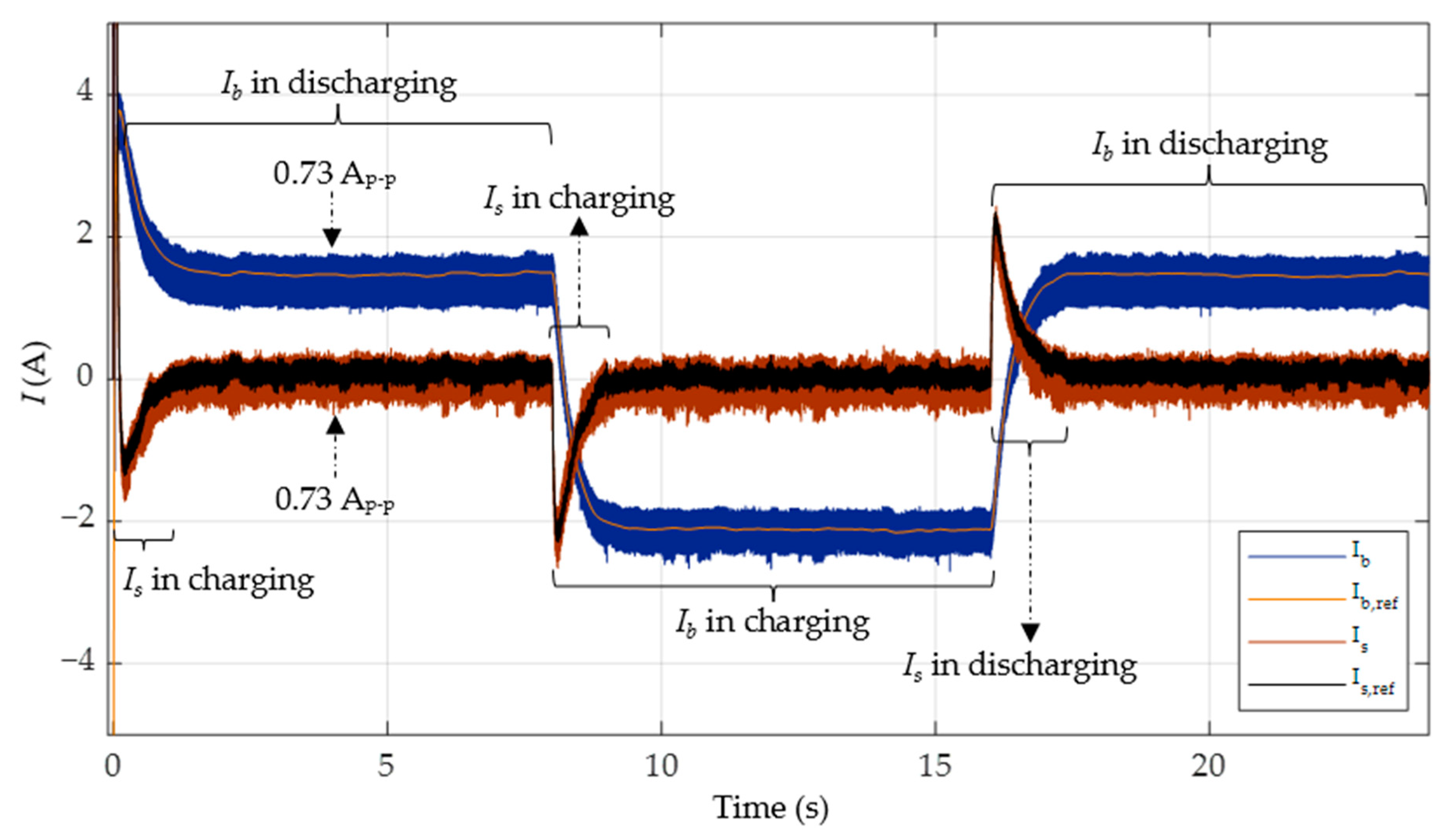
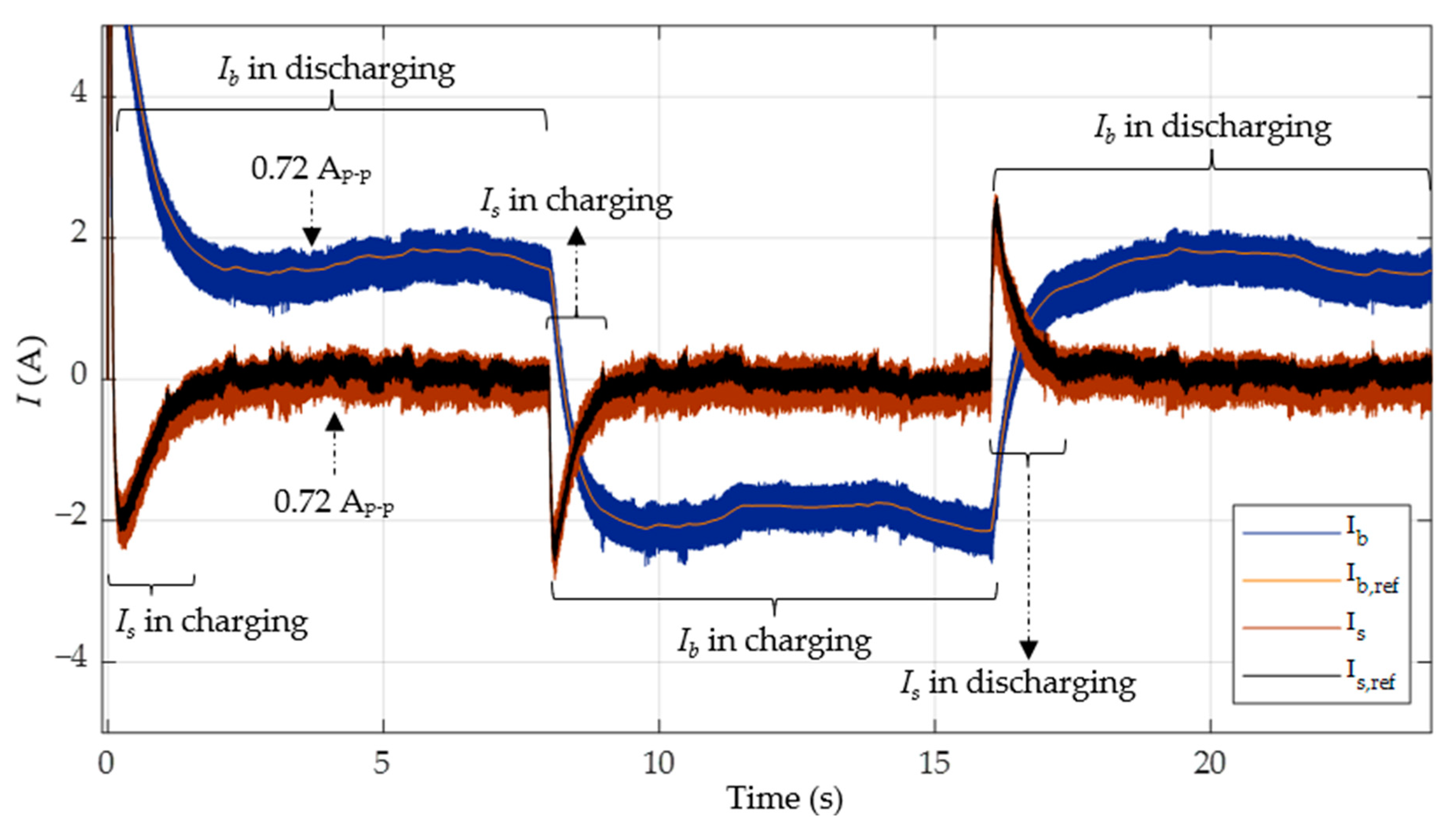
5.4. Case 2: HESS Charging and Discharging under Resistive Load

This case investigates the behavior of an HESS with the following load variations: 21 Ω for 0–8 s, 100 Ω for 8–16 s, and again at 21 Ω for 16–24 s. Figure 17, Figure 18 and Figure 19 depict both the PI-SMC and proposed controller responses, including the battery current, supercapacitor current, and DC bus voltage.
The battery can maintain V dc stability in a steady state by discharging at t = 0 8   s and t = 16 24   s to address the power shortage of 29.71 W, while it charges at t = 8 16   s to store the excess power of 56.96 W. Furthermore, the supercapacitor charges and discharges during the transients to provide proper power delivery during load switching. The charging and discharging of the HESS with PI-SMC and PI-FNITSMC are illustrated in Figure 17 and Figure 18.
Figure 19 shows the DC bus voltage, while Table 5 summarizes the results. These results again show that the proposed controller has a reduced rise time and settling time and has a performance superior to PI-SMC, with minimal overshoots. It is also evident that the battery efficiently stores the excess PV power when the load demand is less.

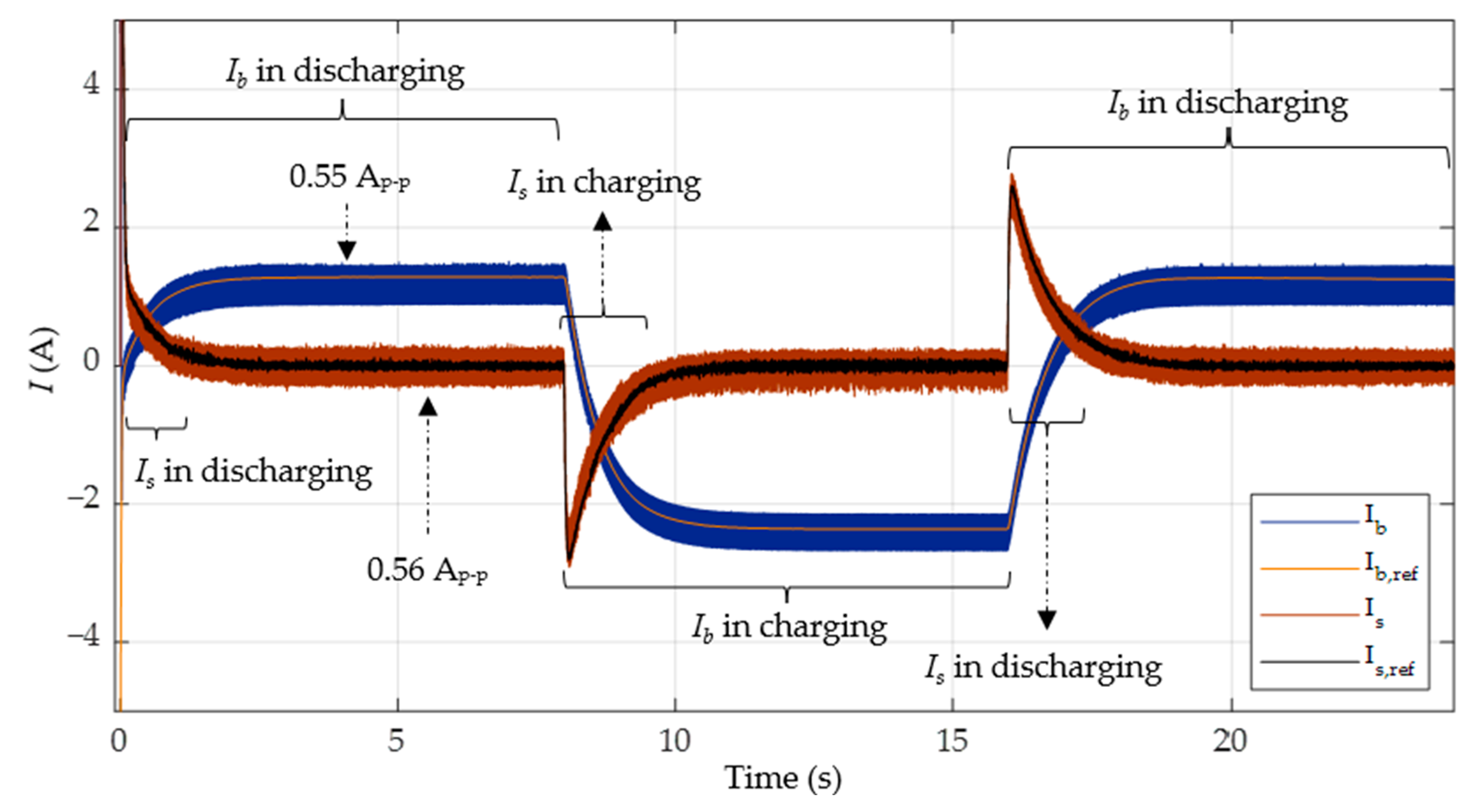
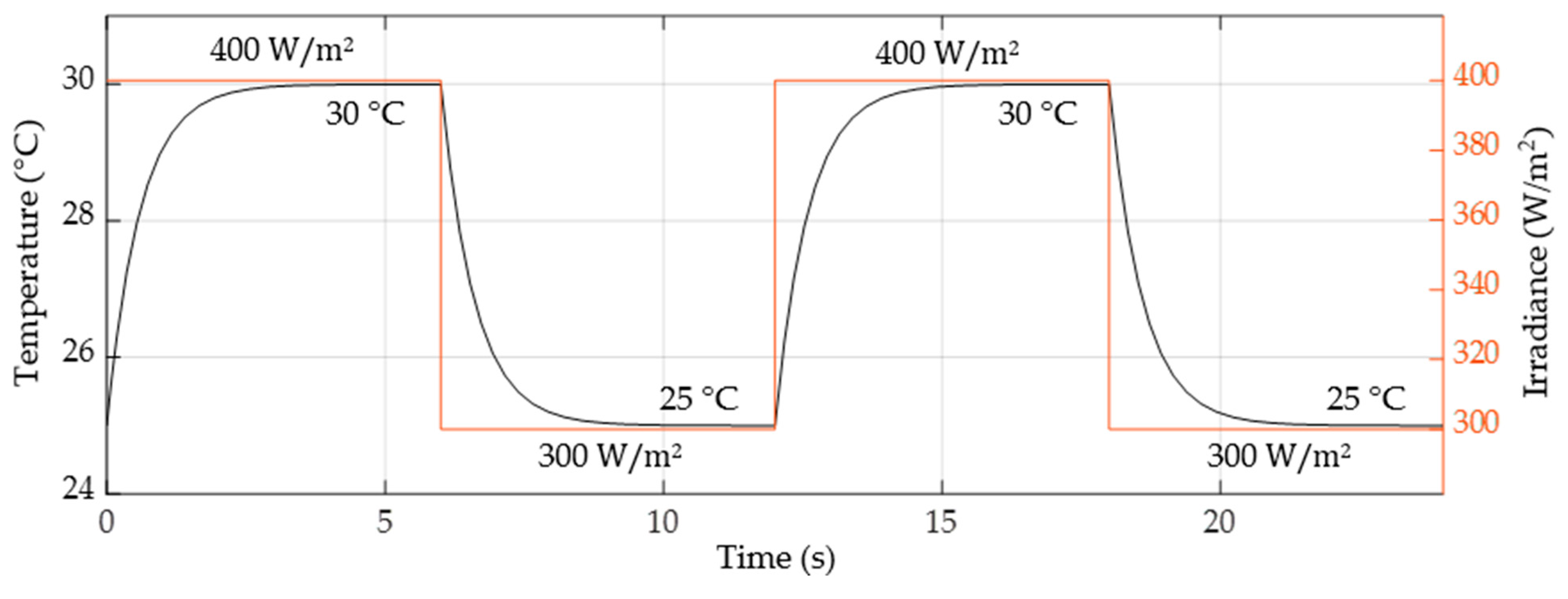
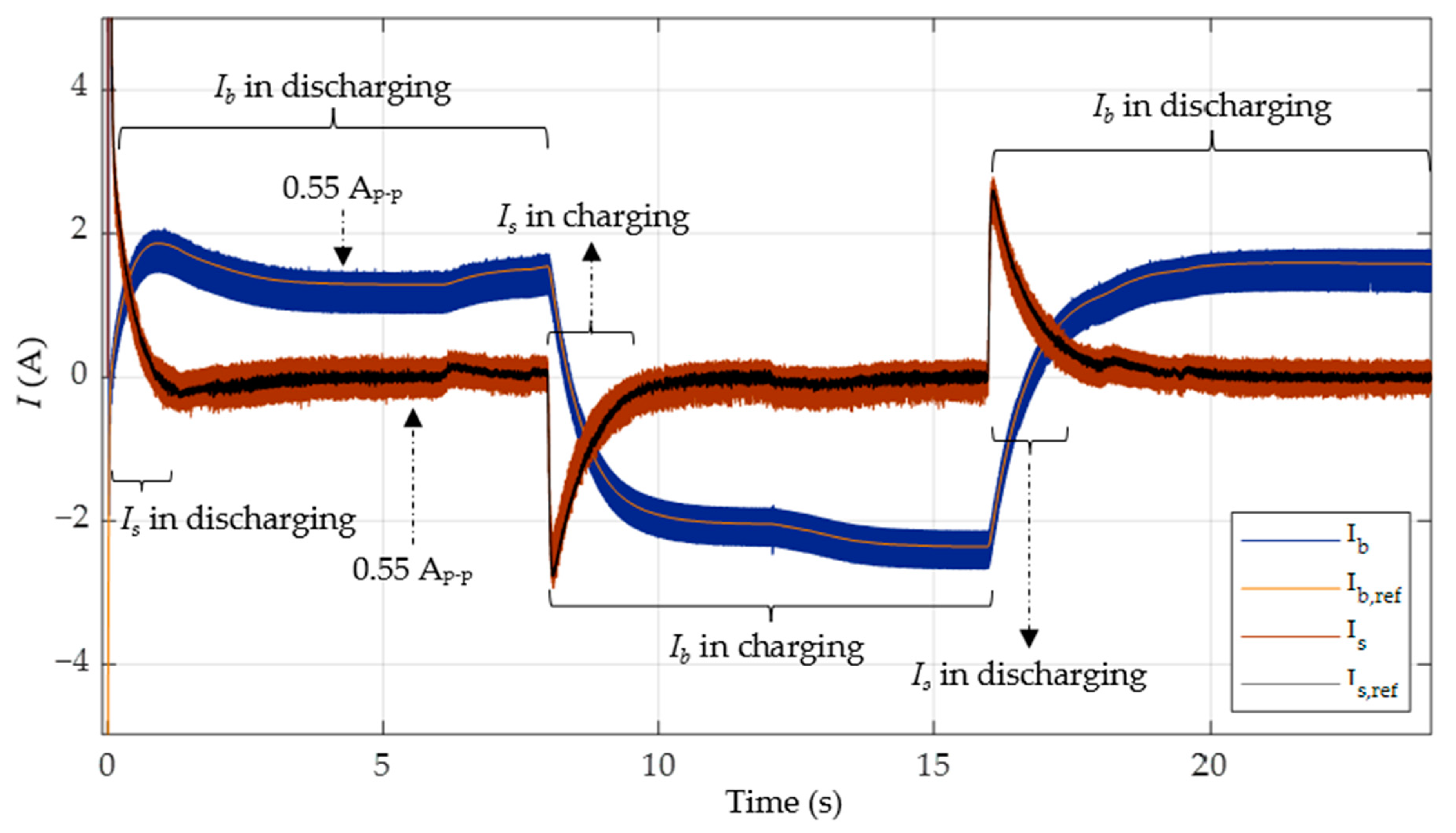
5.5. Case 3: HESS Charging and Discharging under Load Variations at Varying Irradiance and Temperature Levels

This case compares the controllers in terms of the tracking and stability performance with load variations, as shown in Figure 20, along with temperature and irradiance variations, as illustrated in Figure 21. These conditions force the PV module to generate the peak power of 80 W at an irradiance of 400 W/m2 and a temperature of 30 °C, as well as 70 W at an irradiance of 300 W/m2 and a temperature of 25 °C.
Temperature and irradiance certainly have the potential to influence the power output of a PV array. The generated power is a direct output of the irradiance level while the temperature works conversely. There are several studies to correlate the cell/ambient temperature to the generated power. In conclusion, with each 1 °C rise in temperature, the generated power drops by approximately 1.5%. ESS charging and discharging states are the functions of the total generated power, the ESS’s charging state, the bus voltage, and the load demands; they are not directly linked to either the temperature or the irradiance.
The charging and discharging of the HESS for both PI-SMC- and PI-FNITSMC-based controllers are illustrated in Figure 22 and Figure 23. Figure 23 demonstrates that both the SESS and BESS control systems, using the proposed PI-FNITSMC-based controller, can efficiently follow their reference currents. Discharging (at t = 0 8   s and t = 16 24   s ) and charging (at t = 8 16   s ), the battery indicates that the BESS is used to stabilize the V dc in the steady state. Furthermore, the charging and discharging of the supercapacitor occurs during the transient periods to provide proper power during load switching.
Figure 24 shows the DC bus voltage, while Table 6 summarizes the results. These results again show that the proposed controller has a reduced rise time and settling time and has a performance superior to PI-SMC, with minimal overshoots. It is also evident that both the battery and the supercapacitor are properly charged and discharged to efficiently utilize the excess PV power when the load demand is less and stabilize the bus voltage when the demand is more.

5.6. Discussion on the Simulation Results

The above simulations of the three cases compare the performance of the proposed PI-FNITSMC-based control scheme with the PI-SMC-based scheme. It is clear from the obtained results that FNITSMC exhibits all of its properties, like smoothness and robustness. The achieved results are superior to the best possible reported until now. The performance in the transient region shows that the system was able to efficiently maintain the bus voltage with minimal overshoots/undershoots, rise time, and settling time. Similarly, in the steady-state region, the system was able to efficiently extract and inject power depending on the load demands. In case of temperature and irradiance changes, the proposed system shows robust behavior.

6. Conclusions

In this study, a combined PI and FNITSMC-based current sharing algorithm for an HESS, comprising a battery and a supercapacitor, has been investigated and verified using the Typhoon™ HIL-402 platform. The PI coupled with an LPF has successfully distinguished between the current references for a BESS and an SESS. Both the BESS and SESS are controlled by FNITSMC to adjust the power balance in the DC microgrid. The BESS is able to control steady-state power demands, whereas the SESS is successful in controlling transient power demands. The PI-FNITSMC-based proposed controller is able to consistently satisfy the power requirements of a DC microgrid with good transient performance, faster and more precise tracking, and robustness to load variations at various temperatures and irradiances. The rise time and settling time of the proposed controller can be reduced compared to the PI-SMC by defining a modified sliding surface in FNITSMC. FNITSMC is able to reach the equilibrium point with improved tracking accuracy and finite-time convergence. The precise tracking of PI-FNITSMC can be measured by calculating the statistical errors. The IAE of V dc is reduced by 41.2%, 39%, and 39.1% compared to the PI-SMC-based power-sharing method in the three cases. Furthermore, the proposed controller has good robustness to load variations, as evidenced by low V dc fluctuations and lower overshoot/undershoot compared to PI-SMC.
Regarding the future directions of this research, the system will be tested with both resistive and reactive loads to know its performance in a more real-life scenario. Experimental verification with a real-life system will also be of crucial importance. In addition, decentralized DC microgrid HESS stabilization control will be targeted. This will need a separate control design for BESS and SESS stabilization controls without a communication link; this will allow for several BESSs and SESSs on the same DC bus at different locations according to specific local demands, hence flexibly expanding the system without modifying existing control structures. Another line of research will be towards optimizing the transient and steady-state performances through implementing adaptive SMC enhancement. As it is seen in this work that the PWM duty cycle and the load greatly affect the closed-loop stability of the system, future work may further investigate these dependencies and, if feasible, propose an adaptive (for example, gain scheduling) scheme to achieve the optimal behavior.

Author Contributions

Conceptualization, R.U. and K.M.; methodology, M.A.M.R.; software, R.U. and I.M.M.; validation, K.M. and M.A.M.R.; formal analysis, R.U.; investigation, K.M.; resources, I.M.M.; data curation, R.U.; writing—original draft preparation, R.U.; writing—review and editing, K.M. and M.A.M.R.; visualization, R.U.; supervision, K.M. and M.A.M.R.; funding acquisition, K.M. All authors have read and agreed to the published version of the manuscript.

Funding

This research was supported by Institutional Fund Projects under grant no. (IFPIP: 1783-135-1443).

Institutional Review Board Statement

Not applicable.

Informed Consent Statement

Not applicable.

Data Availability Statement

The data presented in this study are available on request from the corresponding author.

Acknowledgments

This research work was funded by Institutional Fund Projects under grant no. (IFPIP: 1783-135-1443). The authors gratefully acknowledge the technical and financial support provided by the Ministry of Education and King Abdulaziz University, DSR, Jeddah, Saudi Arabia.

Conflicts of Interest

The authors declare no conflicts of interest.

Nomenclature

AbbreviationDefinitionAbbreviationDefinition
PVPhotovoltaic d g Duty ratio of the PWM input
ESSEnergy storage system d g 1 d g
HESSHybrid energy storage system V pv , ref PV reference voltage
LPFLow-pass filter N s Number of PV cells in series
HILHardware-in-the-loop K Blotsmann’s constant
MPPMaximum power point A P-N junction characteristic
MPPTMPP tracking T Cell temperature
PIProportional–integral E Irradiance
SMCSliding mode control I rs Reverse saturation current
MPCModel predictive control q Electron charge
FLCFuzzy logic control I ph Photocurrent
VRDVirtual resistance droop I s h Cell short-circuit current
VCDVirtual capacitance droop k is Short-circuit current coefficient
GSMCGlobal SMC V oc Open-circuit voltage
BESSBattery ESS E go Band-gap energy
SESSSupercapacitor ESS σ pv Sliding surface of GSMC
FNITSMCFast nonsingular integral terminal SMC e pv Tracking error of V pv
PWMPulse width modulation sgn Signum function
IAEIntegral absolute error sat Saturation function
ITAEIntegral time absolute error u g PWM input
I L pv Inductor current of PV converter u pv , eq Equivalent control in GSMC
V pv PV output voltage u pv , sw Switching control in GSMC
L pv Inductance of PV converter G pv Switching control gain for PV
C pv Capacitance of PV converter I g , ref Reference current of ESS
V dc DC bus voltage σ g Sliding surface of FNITSMC
d pv Duty ratio of PV converter e g Tracking error of I g
α pv ,   β pv , η PV parameters G g Switching control gain for ESS
g     b For BESS α g ,   β g , γ g ,     k g ,     l g HESS parameters
g     s For SESS u g , eq Equivalent control in FNITSMC
V g Voltage of the ESS u g , sw Switching control in FNITSMC
V L 1 g Voltage of Ćuk converter’s   L 1 g K p Proportional gain of PI controller
V L 2 g Voltage of Ćuk converter’s   L 2 g K i Integral gain of PI controller
V C g Voltage of Ćuk converter’s C g V dc , ref DC voltage reference
V C og Voltage of Ćuk converter’s C o g I b , ref Current reference for BESS
R Load I s , ref Current reference for SESS

References

  1. REN21. Renewables 2023 Global Status Report Collection, Renewables in Energy Supply; REN21: Paris, France, 2023. [Google Scholar]
  2. REN21. Renewables 2023 Global Status Report Collection, Renewables in Energy Demand; REN21: Paris, France, 2023. [Google Scholar]
  3. Shaik, F.; Lingala, S.S.; Veeraboina, P. Effect of various parameters on the performance of solar PV power plant: A review and the experimental study. Sustain. Energy Res. 2023, 10, 6. [Google Scholar] [CrossRef]
  4. Lee, J.; Shepley, M.M.C. Benefits of solar photovoltaic systems for low-income families in social housing of Korea: Renewable energy applications as solutions to energy poverty. J. Build. Eng. 2020, 28, 101016. [Google Scholar] [CrossRef]
  5. Karanayil, B.; Ceballos, S.; Pou, J. Maximum Power Point Controller for Large Scale Photovoltaic Power Plants Using Central Inverters under Partial Shading Conditions. IEEE Trans. Power Electron. 2018, 34, 3098–3109. [Google Scholar] [CrossRef]
  6. Zhang, X.; Wang, B.; Gamage, D.; Ukil, A. Model predictive and iterative learning control based hybrid control method for hybrid energy storage system. IEEE Trans. Sustain. Energy 2021, 12, 2146–2158. [Google Scholar] [CrossRef]
  7. Wang, X.; Yu, D.; Le Blond, S.; Zhao, Z.; Wilson, P. A novel controller of a battery-supercapacitor hybrid energy storage system for domestic applications. Energy Build. 2017, 141, 167–174. [Google Scholar] [CrossRef]
  8. Lin, P.; Deng, C.; Yang, Y.; Lee, C.H.T.; Tay, W.P. Resilience-Oriented Control for Cyber-Physical Hybrid Energy Storage Systems Using a Semiconsensus Scheme: Design and Practice. IEEE Trans. Ind. Electron. 2023, 70, 2508–2519. [Google Scholar] [CrossRef]
  9. Wang, Z.; Wang, P.; Jiang, W.; Wang, P.A. Decentralized Automatic Load Power Allocation Strategy for Hybrid Energy Storage System. IEEE Trans. Energy Convers. 2021, 36, 2227–2238. [Google Scholar] [CrossRef]
  10. Javed, K.; Ashfaq, H.; Singh, R.; Hussain, S.M.S.; Ustun, T.S. Design and performance analysis of a stand-alone PV system with hybrid energy storage for rural India. Electronics 2019, 8, 952. [Google Scholar] [CrossRef]
  11. Lu, Y.; Liu, Z.; Lyu, J.; Wei, X. Hierarchical Power Allocation Control for Star-Connected Hybrid Energy Storage System Using Cascaded Multilevel Converters. Front. Energy Res. 2021, 9, 748508. [Google Scholar] [CrossRef]
  12. Kakigano, H.; Miura, Y.; Ise, T. Distribution voltage control for DC microgrids using fuzzy control and gain-scheduling technique. IEEE Trans. Power Electron. 2013, 28, 2246–2258. [Google Scholar] [CrossRef]
  13. Mumtaz, F.; Zaihar Yahaya, N.; Tanzim Meraj, S.; Singh, B.; Kannan, R.; Ibrahim, O. Review on non-isolated DC-DC converters and their control techniques for renewable energy applications. Ain Shams Eng. J. 2021, 12, 3747–3763. [Google Scholar] [CrossRef]
  14. Magzoub, M.A.; Alquthami, T. Optimal Design of Automatic Generation Control Based on Simulated Annealing in Interconnected Two-Area Power System Using Hybrid PID-Fuzzy Control. Energies 2022, 15, 1540. [Google Scholar] [CrossRef]
  15. Yang, N.; Paire, D.; Gao, F.; Miraoui, A.; Liu, W. Compensation of droop control using common load condition in DC microgrids to improve voltage regulation and load sharing. Int. J. Electr. Power Energy Syst. 2015, 64, 752–760. [Google Scholar] [CrossRef]
  16. Dragicevic, T.; Lu, X.; Vasquez, J.C.; Guerrero, J.M. DC Microgrids—Part I: A Review of Control Strategies and Stabilization Techniques. IEEE Trans. Power Electron. 2016, 31, 4876–4891. [Google Scholar] [CrossRef]
  17. Guo, F.; Wen, C.; Mao, J.; Song, Y.D. Distributed Secondary Voltage and Frequency Restoration Control of Droop-Controlled Inverter-Based Microgrids. IEEE Trans. Ind. Electron. 2015, 62, 4355–4364. [Google Scholar] [CrossRef]
  18. Xu, Q.; Hu, X.; Wang, P.; Xiao, J.; Tu, P.; Wen, C.; Lee, M.Y. A Decentralized Dynamic Power Sharing Strategy for Hybrid Energy Storage System in Autonomous DC Microgrid. IEEE Trans. Ind. Electron. 2017, 64, 5930–5941. [Google Scholar] [CrossRef]
  19. Xu, Q.; Xiao, J.; Wang, P.; Pan, X.; Wen, C. A Decentralized Control Strategy for Autonomous Transient Power Sharing and State-of-Charge Recovery in Hybrid Energy Storage Systems. IEEE Trans. Sustain. Energy 2017, 8, 1443–1452. [Google Scholar] [CrossRef]
  20. Xu, Q.; Xiao, J.; Hu, X.; Wang, P.; Lee, M.Y. A Decentralized Power Management Strategy for Hybrid Energy Storage System with Autonomous Bus Voltage Restoration and State-of-Charge Recovery. IEEE Trans. Ind. Electron. 2017, 64, 7098–7108. [Google Scholar] [CrossRef]
  21. Ramos, G.A.; Costa-Castelló, R. Energy Management Strategies for Hybrid Energy Storage Systems Based on Filter Control: Analysis and Comparison. Electronics 2022, 11, 1631. [Google Scholar] [CrossRef]
  22. Vijayan, M.; Udumula, R.R.; Mahto, T.; Lokeshgupta, B.; Goud, B.S.; Kalyan, C.N.S.; Balachandran, P.K.; Padmanaban, S.; Twala, B. Optimal PI-Controller-Based Hybrid Energy Storage System in DC Microgrid. Sustainability 2022, 14, 14666. [Google Scholar] [CrossRef]
  23. Joshi, M.C.; Samanta, S. Improved Energy Management Algorithm with Time Share Based UC Charging/Discharging for Hybrid Energy Storage System. IEEE Trans. Ind. Electron. 2018, 66, 6032–6043. [Google Scholar] [CrossRef]
  24. Cabrane, Z.; Ouassaid, M.; Maaroufi, M.; Marhraoui, S.; Hichami, N.L. Two proposed Control Algorithm of the Management of Supercapacitors-Batteries combination in Photovoltaic Energy Storage. In Proceedings of the 2018 6th International Renewable and Sustainable Energy Conference (IRSEC), Rabat, Morocco, 5–8 December 2018. [Google Scholar]
  25. Cabrane, Z.; Ouassaid, M.; Maaroufi, M. Battery and supercapacitor for photovoltaic energy storage: A fuzzy logic management. IET Renew. Power Gener. 2017, 11, 1157–1165. [Google Scholar] [CrossRef]
  26. Cabrane, Z.; Kim, J.; Yoo, K.; Ouassaid, M. HESS-based photovoltaic/batteries/supercapacitors: Energy management strategy and DC bus voltage stabilization. Sol. Energy 2020, 216, 551–563. [Google Scholar] [CrossRef]
  27. Hredzak, B.; Agelidis, V.G. Model predictive control of a hybrid battery-ultracapacitor power source. In Proceedings of the 7th International Power Electronics and Motion Control Conference (IPEMC), Harbin, China, 2–5 June 2012; pp. 2294–2299. [Google Scholar]
  28. Hredzak, B.; Agelidis, V.G.; Jang, M. A model predictive control system for a hybrid battery-ultracapacitor power source. IEEE Trans. Power Electron. 2014, 29, 1469–1479. [Google Scholar] [CrossRef]
  29. Song, Z.; Park, H.; Delgado, F.P.; Wang, H.; Li, Z.; Hofmann, H.; Sun, J.; Hou, J. Simultaneous identification and control for hybrid energy storage system using model predictive control and active signal injection. IEEE Trans. Ind. Electron. 2020, 67, 9768–9778. [Google Scholar] [CrossRef]
  30. Hou, J.; Song, Z.; Hofmann, H.; Sun, J. Adaptive model predictive control for hybrid energy storage energy management in all-electric ship microgrids. Energy Convers. Manag. 2019, 198, 111929. [Google Scholar] [CrossRef]
  31. Muktiadji, R.F.; Ramli, M.A.M.; Bouchekara, H.R.E.H.; Milyani, A.H.; Rawa, M.; Seedahmed, M.M.A.; Budiman, F.N. Control of Boost Converter Using Observer-Based Backstepping Sliding Mode Control for DC Microgrid. Front. Energy Res. 2022, 10, 828978. [Google Scholar] [CrossRef]
  32. Ma’arif, A.; Vera MA, M.; Mahmoud, M.S.; Ladaci, S.; Cakan, A.; Parada, J.N. Backstepping Sliding Mode Control for Inverted Pendulum System with Disturbance and Parameter Uncertainty. J. Robot. Control. 2022, 3, 86–92. [Google Scholar] [CrossRef]
  33. Liu, J.; Wang, X. Advanced Sliding Mode Control for Mechanical Systems; Tsinghua University Press: Beijing, China, 2012. [Google Scholar]
  34. Zhihong, M.; Yu, X.H. Terminal Sliding Mode Control of MIMO Linear Systems. IEEE Trans. Circuits Syst. I Fundam. Theory Appl. 1996, 44, 1065–1069. [Google Scholar] [CrossRef]
  35. Singh, P.; Lather, J.S. Dynamic current sharing, voltage, and SOC regulation for HESS based DC microgrid using CPISMC technique. J. Energy Storage 2020, 30, 101509. [Google Scholar] [CrossRef]
  36. Abianeh, A.J.; Ferdowsi, F. Sliding Mode Control Enabled Energy Storage System for Islanded DC Microgrids with Pulsing Loads. Sustain. Cities Soc. 2021, 73, 103117. [Google Scholar] [CrossRef]
  37. Fu, D.; Zhao, X. A Novel Robust Adaptive Nonsingular Fast Integral Terminal Sliding Mode Controller for Permanent Magnet Linear Synchronous Motors. IEEE J. Emerg. Sel. Top. Power Electron. 2023, 11, 1672–1683. [Google Scholar] [CrossRef]
  38. Qiao, L.; Zhang, W. Trajectory Tracking Control of AUVs via Adaptive Fast Nonsingular Integral Terminal Sliding Mode Control. IEEE Trans. Ind. Inform. 2020, 16, 1248–1258. [Google Scholar] [CrossRef]
  39. Safari, A.; Mekhilef, S. Simulation and hardware implementation of incremental conductance MPPT with direct control method using Ćuk converter. IEEE Trans. Ind. Electron. 2011, 58, 1154–1161. [Google Scholar] [CrossRef]
  40. Hu, W.; Ding, Z.; Yang, H.; Tao, J.; Wang, X. Stability analysis and stabilization of Ćuk converter with constant power load. Int. J. Circuit Theory Appl. 2023, 51, 1685–1696. [Google Scholar] [CrossRef]
  41. Mahafzah, K.A.; Al-Shetwi, A.Q.; Hannan, M.A.; Babu, T.S.; Nwulu, N. A New Cuk-Based DC-DC Converter with Improved Efficiency and Lower Rated Voltage of Coupling Capacitor. Sustainability 2023, 15, 8515. [Google Scholar] [CrossRef]
  42. Uswarman, R.; Munawar, K.; Ramli, M.A.M.; Bouchekara, H.R.E.H.; Hossain, M.A. Maximum Power Point Tracking in Photovoltaic Systems Based on Global Sliding Mode Control with Adaptive Gain Scheduling. Electronics 2023, 12, 1128. [Google Scholar] [CrossRef]
  43. Khan, K.A.; Khalid, M. Improving the Transient Response of Hybrid Energy Storage System for Voltage Stability in DC Microgrids Using an Autonomous Control Strategy. IEEE Access 2021, 9, 10460–10472. [Google Scholar] [CrossRef]
  44. Wang, B.; Manandhar, U.; Zhang, X.; Gooi, H.B.; Ukil, A. Deadbeat Control for Hybrid Energy Storage Systems in DC Microgrids. IEEE Trans. Sustain. Energy 2019, 10, 1867–1877. [Google Scholar] [CrossRef]
  45. Martinez-Trevino, B.A.; El Aroudi, A.; Cid-Pastor, A.; Garcia, G.; Martinez-Salamero, L. Synthesis of Constant Power Loads Using Switching Converters under Sliding-Mode Control. IEEE Trans. Circuits Syst. I Regul. Pap. 2021, 68, 524–535. [Google Scholar] [CrossRef]
  46. Ramos-Paja, C.A.; Gonzalez Montoya, D.; Bastidas-Rodríguez, J.D. Sliding-mode control of a Ćuk converter for voltage regulation of a dc-bus. Sustain. Energy Technol. Assess. 2020, 42, 100807. [Google Scholar] [CrossRef]
  47. Dahech, K.; Allouche, M.; Damak, T.; Tadeo, F. Backstepping sliding mode control for maximum power point tracking of a photovoltaic system. Electr. Power Syst. Res. 2017, 143, 182–188. [Google Scholar] [CrossRef]
  48. Suryawanshi, P.V.; Shendge, P.D.; Phadke, S.B. A boundary layer sliding mode control design for chatter reduction using uncertainty and disturbance estimator. Int. J. Dynamic. Control. 2016, 4, 456–465. [Google Scholar] [CrossRef]
  49. Wang, Y.; Feng, Y.; Zhang, X.; Liang, J.; Cheng, X. New Reaching Law Control for Permanent Magnet Synchronous Motor with Extended Disturbance Observer. IEEE Access 2019, 7, 186296–186307. [Google Scholar] [CrossRef]
  50. Garg, M.M.; Hote, Y.V.; Pathak, M.K. Leverrier’s Algorithm based Modeling of HIgher-order dc-dc Converters. In Proceedings of the 2012 IEEE 5th India International Conference on Power Electronics (IICPE), Delhi, India, 6–8 December 2012; pp. 1–6. [Google Scholar]
  51. Arunkumar, C.R.; Manthati, U.B. A Hybrid Controller Assisted Voltage Regulation and Power Splitting Strategy for Battery/Supercapacitor System in Isolated DC Microgrid. IEEE Trans. Energy Convers. 2023, 38, 1544–1553. [Google Scholar]
  52. Majji, R.K.; Mishra, J.P.; Dongre, A.A. Model predictive control based autonomous DC microgrid integrated with solar photovoltaic system and composite energy storage. Sustain. Energy Technol. Assess. 2022, 54, 102862. [Google Scholar] [CrossRef]
  53. Kathi, L. Small-Signal Analysis of Non-Isolated Ćuk DC-DC Converter. Ph.D. Thesis, Wright State University, Dayton, OH, USA, 2020. [Google Scholar]
  54. Rytkonen, F.J.; Tymerski, R. Modern Control Regulator Design for DC-DC Converters; Portland State University: Portland, OR, USA, 2005. [Google Scholar]
  55. Su, J.; Li, K.; Zhang, L.; Pan, X.; Yu, J. A Decentralized Power Allocation Strategy for Dynamically Forming Multiple Hybrid Energy Storage Systems Aided with Power Buffer. IEEE Trans. Sustain. Energy 2023, 14, 1714–1724. [Google Scholar] [CrossRef]
Figure 1. Workflow of this research.
Sustainability 16 02307 g001
Figure 2. Configuration of DC microgrid with PV and HESS.
Sustainability 16 02307 g002
Figure 3. (a) Bidirectional DC–DC Ćuk converter; (b) switch on; (c) switch off.
Sustainability 16 02307 g003
Figure 6. The illustration of sliding mode.
Sustainability 16 02307 g006
Figure 7. MPPT control of PV system under standard operating conditions (25 °C, 1000 W/m2).
Sustainability 16 02307 g007
Figure 8. Extracted power of PV system under standard operating conditions (25 °C, 1000 W / m 2 ).
Sustainability 16 02307 g008
Figure 9. Root loci of the bidirectional Ćuk converter with varying d g and a load of 15 Ω.
Sustainability 16 02307 g009
Figure 10. Root loci of the bidirectional Ćuk converter with varying d g and a load of 21 Ω.
Sustainability 16 02307 g010
Figure 11. Root loci of the bidirectional Ćuk converter with varying d g and a load of 100 Ω.
Sustainability 16 02307 g011
Figure 12. Block diagram of complete BESS control.
Sustainability 16 02307 g012
Figure 13. Block diagram of complete SESS control.
Sustainability 16 02307 g013
Figure 14. Battery current ( I b )   and supercapacitor current ( I s ) in case 1 with PI-SMC.
Sustainability 16 02307 g014
Figure 15. Battery current ( I b ) and supercapacitor current ( I s ) in case 1 with PI-FNITSMC.
Sustainability 16 02307 g015
Figure 16. DC bus voltage ( V dc ) in discharging HESS.
Sustainability 16 02307 g016
Figure 17. Battery current ( I b ) and supercapacitor current ( I s ) in case 2 with PI-SMC.
Sustainability 16 02307 g017
Figure 18. Battery current ( I b ) and supercapacitor current ( I s ) in case 2 with PI-FNITSMC.
Sustainability 16 02307 g018
Figure 19. DC bus voltage ( V dc ) in charging and discharging HESS.
Sustainability 16 02307 g019
Figure 20. Load variations in case 3.
Sustainability 16 02307 g020
Figure 21. Temperature and irradiance variations in case 3.
Sustainability 16 02307 g021
Figure 22. Battery current ( I b ) and supercapacitor current ( I s ) in case 3 with PI-SMC.
Sustainability 16 02307 g022
Figure 23. Battery current ( I b ) and supercapacitor current ( I s ) in case 3 with PI-FNITSMC.
Sustainability 16 02307 g023
Figure 24. DC bus voltage ( V dc ) in case 3 using PI-SMC and PI-FNITSMC.
Sustainability 16 02307 g024
Table 1. Summary of the existing control strategies of DC microgrid control with HESS.
ControllersAdvantagesLimitationsOvershoot/
Undershoot
Statistical ErrorsConsidering
Uncertainty
FLC-gain scheduling [12,13]
  • Mathematical model of the system is not required.
  • Challenging to determine the appropriate fuzzy rules and membership functions.
5%
Droop control-PI [18,19,20]
  • Decentralized strategy without communications and central controllers.
  • Virtual resistance and capacitance droop must be accurate; incorrect values result in unstable DC bus voltage.
1.9%
PI-PI [13,24,25,26]
  • Simple implementation.
  • Faster transient response.
  • Unable to address the impact of intermittent nature and uncertainties of renewable resources.
  • High overshoots.
3.5%
MPC [13,28,29,30]
  • Efficient tracking due to good system estimation.
  • Improved transient response.
  • Sensitive to unmodeled uncertainties.
  • High computational burden.
1%
PI-SMC [35,36]
  • Insensitive to model uncertainties.
  • Robust to model nonlinearities.
  • Simple and tunable controller structure.
  • Chattering effect.
  • Uncertain time convergence.
3.8%
This table compares the advantages, disadvantages, and some performance metrics. None of these schemes are studied for statistical tracking errors.
Table 2. System parameters [43,44].
DC bus voltage48 V
PV array parametersValues
Maximum power ( P mpp )200 W
Maximum output voltage ( V mpp )26.3 V
Maximum output current ( I mpp )7.61 A
Open-circuit voltage ( V oc )32.9 V
Short-circuit current ( I sc )8.21 A
Battery specificationsValues
TypeLead Acid
Terminal voltage ( V b )24 V
Ah capacity17 Ah
Rated energy408 Wh
Supercapacitor specificationsValues
Terminal voltage ( V s )32 V
Capacitance58 F
Rated energy4.2 Wh
Boost converter parametersValues
Capacitor ( C pv , C opv )440 µF, 6 mF
Converter inductor ( L pv )2 mF
Switching frequency50 kHz
HESS parametersValues
Capacitor ( C g ,   C og )10 µF
Inductor ( L 1 g , L 2 g )6.3 mH, 1.3 mH
Switching frequency50 kHz
Controller parametersValues
PV parameters ( α pv , β pv , η )0.16, 0.01, 0.1
HESS parameters ( α g , β g , γ g , k g , l g )1.6, 1.2, 0.1, 1.7, 1.2
Constant gain ( G pv ,   G g ) 100
Table 3. The transient response with varying load resistance.
15 Ω ≡ 153.6 W @ 48 V21 Ω ≡ 109.71 W @ 48 V100 Ω ≡ 23.04 W @ 48 V
Rise timeSettling timeRise timeSettling timeRise timeSettling time
1.1 ms28.5 ms0.8 ms28.9 ms0.6 ms46.4 ms
Table 4. Transient performance and V dc errors in case 1.
ControllerRise TimeSettling TimeOvershoot/Undershoot
0–1 s; 8–9 s; 16–17 s
IAEITAE
PI-SMC26.7 ms527 ms4.9%; 1.6%; 1.6%3.413.7
PI-FNITSMC25.2 ms65 ms0.1%; 1.3%; 1.3%2.08.1
Table 5. Transient performance and V dc errors in case 2.
ControllerRise TimeSettling TimeOvershoot/Undershoot
0–1 s; 8–9 s; 16–17 s
IAEITAE
PI-SMC27.3 ms521 ms4.6%; 3.3%; 3.1%4.122.4
PI-FNITSMC25.2 ms65 ms0.06%; 2.5%; 2.4%2.513.8
Table 6. Transient performance and V dc errors in case 3.
ControllerRise TimeSettling TimeOvershoot/Undershoot
0–1 s; 8–9 s; 16–17 s
IAEITAE
PI-SMC32.1 ms591 ms3.1%; 3.3%; 3.2%4.627.3
PI-FNITSMC25.2 ms88.2 ms0.3%; 2.6%; 2.4%2.814.7
Disclaimer/Publisher’s Note: The statements, opinions and data contained in all publications are solely those of the individual author(s) and contributor(s) and not of MDPI and/or the editor(s). MDPI and/or the editor(s) disclaim responsibility for any injury to people or property resulting from any ideas, methods, instructions or products referred to in the content.

