Abstract
The mass of a direct-drive generator is often defined by the requirements for structural stiffness to meet the magnetic stiffness between the rotor and stator surfaces. This paper analyses this magnetic stiffness and estimates the structural stiffness of direct-drive generators for different modes of deflection. The magnetic stiffness modelling is based on an analytical model of the airgap closing forces. The final models are verified using finite element analysis and developed for both permanent magnet and wound rotor generators. It shows that wound rotor machines have higher stiffness requirements than permanent magnet machines. The structural stiffness of the generator rotor and stator is evaluated for different modes by applying spatially varying forces and finding the associated deflections. Structural stiffnesses for the rotor, stator and bearing are then combined. Finally, the magnetic and structural stiffnesses are combined and a stiffness margin can be found. This method is applied to a relatively stiff and a relatively compliant set of generator structures in a case study. The analytical model presented in this paper is useful for structural optimisation purposes or as part of an online structural health monitoring system as it could assess the integrity of the machines in real time.
1. Introduction
Direct-drive electrical generators are low-speed high-torque machines whose robust and stiff supporting structures are designed to withstand the significant loads present during the assembly and operation stages. From the active material viewpoint, detailed analyses were performed and validated. An experimental evaluation of a five-phase permanent magnet synchronous generator for wind energy purposes and an accurate model of the airgap dynamic reluctance was developed by Kumar in [1]. The model, which considers leakage flux paths, is suitable for the design and optimisation of the generator’s active material. This validation was carried out through an experimental investigation that retrieved results showing good agreement with the data obtained making use of finite element methods. With the same aim, Modelica language, and in particular the wind turbine modelling package, was employed in different studies to simplify and reduce time in the modelling process [2]. A comprehensive overview of the different methods and their applicability to model wind turbine electrical generators for power system stability was given by He in [3].
Less investigation has been made paying attention to the structural material, also known as inactive material. In [4], Polinder et al. presented an overview of the design of different types of wind turbine powertrains for a 3 MW wind turbine, evaluating losses and costs for the wind turbine generator, power converter and gearbox (if used). Costs for the active material were calculated, but generator non-active materials were estimated. In [5], Bywaters et al. identified the outer diameter and cooling method as critical parameters to estimate the total cost of permanent magnet machines. Grauers [6] introduced an analytical cost estimation for these generator structural materials based on dimensional similarity, but it did not take into account the different magnitude of loads from one design to another. In [7], Versteegh provided a detailed description of the design of a low-speed direct-drive permanent magnet generator for the Zephyros Z72 wind turbine where the influence of the loads on the generator design is analysed. The key load to be considered when designing this type of device is a large force across the airgap which is because of the normal component of the Maxwell stress.
Several approaches were described by McDonald in [8] for estimating the mass of machine structures dealing with uniformly distributed force and deflection, also known as Mode 0. By assuming that the rotor and the stator structures were made up of disc and arm sub-structures, the authors linked the electromagnetic and mechanical design to model radial, tangential and axial deformations in radial flux machines. A set of simplified rotor and stator structural configurations that can be used to model the electrical generator are introduced by Stander in [9] and analysed in detail by Jaen-Sola [10]. Klinger showed how different wind turbine designers take different approaches to the design of the structural elements of the direct-drive generator in [11]. Making use of an analytical and finite element analysis optimisation method, Zavvos tried to minimise the structural mass of a permanent magnet direct-drive generator in [12]. Three different iron-cored generator configurations rated at 5 MW were optimised, concluding that a specific transverse flux direct-drive topology is the most suitable as its electromagnetic layout helps the structural design.
In [13], Tavner and Spooner introduced a method which describes the challenge in terms of stiffness, focusing the attention on Mode 1 deflection of the rotor and stator structures. Following that path, Jaen-Sola presented in [10] an electromagnetic analytical model that can be utilised to calculate the required airgap stiffness for multiple modes. In this paper, the authors go a step beyond by coupling this model with a structural model of the inactive material, which was produced using finite element methods.
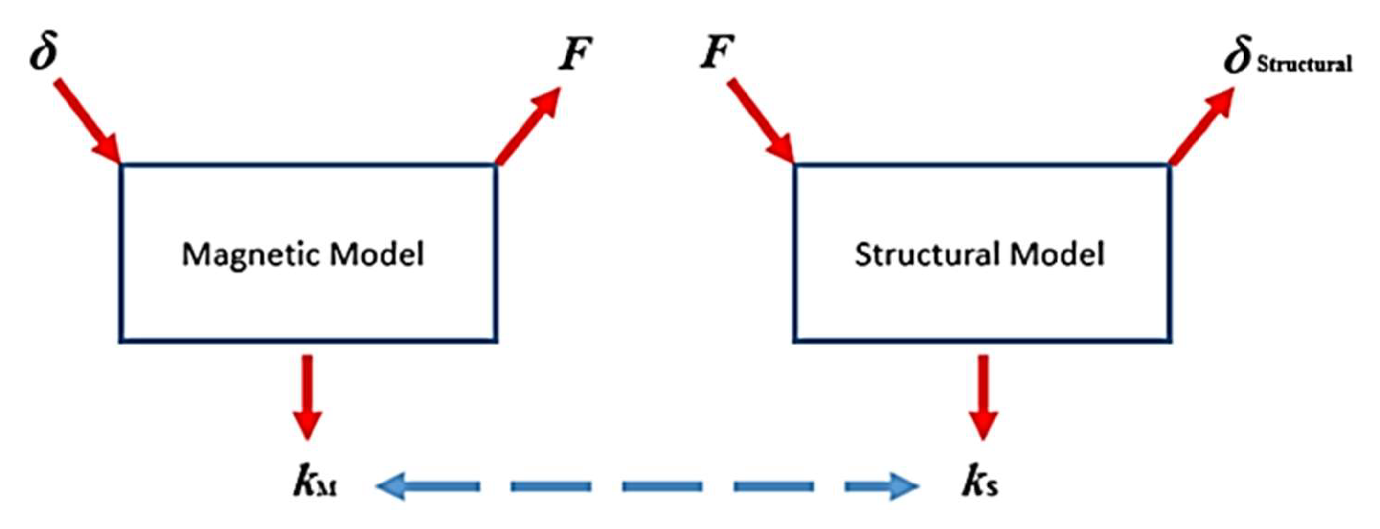
The analytical parametric model first assumes a deflection value that is distributed along the outer surface of the rotor and the inner surface of the stator in order to calculate the ultimate airgap closing force for deflection modes ranging from 0 to 4. Using the deflection and the resultant force, the airgap stiffness is estimated. Finite element analysis of a two-pole model is used afterwards to validate the analytical models for airgap closing force and stiffness. With the analytical models corroborated, a structural finite element model of the electrical machine is generated. Making use of the airgap closing force computed with the analytical approach, a deflection is obtained and used to calculate the structural stiffness that will be compared to the already-known magnetic stiffness so that the designer can understand if the airgap of the proposed structure will remain stable and what the margin of deformation is. See Figure 1.
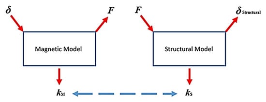
Figure 1.
Coupling of magnetic and structural models.
By knowing the margin of deformation, the designer can change the structural design, e.g., reducing the mass of the sub-structures forming the rotor and stator by modifying their thicknesses.
2. Introduction to the Stiffness Concept
2.1. Mechanical Stiffness
In general terms, stiffness is a measure of the resistance offered by an elastic body to a force deforming the body. The stiffness is defined as k = F/δ, where F is the force and δ is the displacement and it can be used to relate any F and δ, whereas a finite element model of a structure only gives δ for one set of F. This concept of stiffness can be expressed in terms of stress (the force per unit area, σ = F/A), strain (the change in length divided by the original length, ε = δ/l) and major dimensions of the body, thus,
Normally, one is interested in the strain response to the application of stress. A positive value of stiffness means that as a positive force is applied, the change in length is also positive. Occasionally, the stress itself depends on the strain. This is the case for the magnetic forces in the airgap. Here, as the airgap clearance reduces in size (i.e., δ is negative), the magnitude of the forces becomes larger. Conversely, as the airgap clearance increases in size, the magnitude of the force trying to close the airgap reduces. In this case, the stiffness is negative.
In the steady state and with no external forces applied, stability is achieved, and a system is “stiff enough” when the sum of all the values of stiffness is equal to 0. More stiffness is needed when other forces are introduced.
Most systems are made up of multiple bodies, each with its own value of stiffness. Two bodies with stiffness kA and kB can be combined into an equivalent stiffness depending on whether they are in series (and hence experience the same force but have different displacements),
or in parallel (and hence experience the same displacement but different applied forces),
or in a mixture of these two cases.
A cross section of a generator structure with a simplified structure for a direct-drive wind turbine is shown in Figure 2a,b. A radial flux generator is formed by four main components that in terms of stiffness are as follows: the bearing kb, the structure of the rotor ks,r, the magnetic airgap stiffness kM, and the structure of the stator ks,s. Combining the bearing and the rotor structure in series gives an equivalent stiffness,
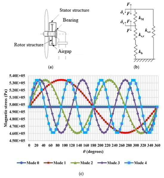
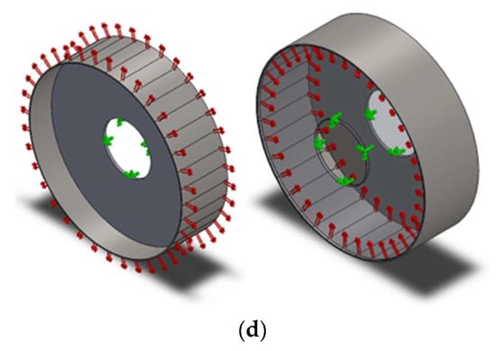
Figure 2.
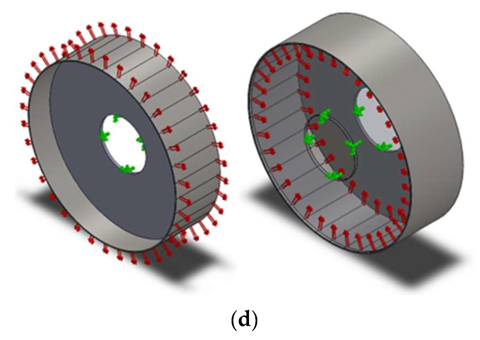
(a) Generator structure; (b) shown as stiffness [10]; (c) magnetic stress vs. Theta for different deflection modes; (d) rotor and stator disc structure models showing loading conditions and constraints [8,9,10].
The magnetic attracting force acting on the rotor and stator surface also acts to deform the rotor and stator structures. These structures have values of stiffness, which are constant for elastic materials below the elastic limit. Equation (5a,b) express the common force in terms of stiffness and deflection,
As they are connected to one another at the generator mounting point, and as they have the same force applied to them both, one can consider them as two bodies with stiffness in series, and so they can be expressed as an equivalent structural stiffness, At one end of this composite structure, the force leads to rotor deflection into the airgap, and at the other end, the force leads to stator deflection,
2.2. Magnetic Stiffness
With a force F, caused by the normal component of the Maxwell stress, acting on the rotor and stator outer and inner surfaces, respectively, the airgap tends to close. See Figure 2c for the loading conditions applied to the simplified structure presented in Figure 2d. The results from the static structural finite element analysis performed on the inactive material of the generator rotor are shown in Figure 3. For the simulation study, the structure was constrained at the shaft. A convergence test retrieved a high-quality linear tetrahedral mesh with 7682 elements and 15,640 nodes. The element size was 148.5 mm. The airgap closing force ‘Fc’, can be expressed in terms of a magnetic stiffness ‘kM’, an assumed ‘’ and a variable deflection ‘δ∆’, which changes with angle ‘θ’, that alters the airgap clearance;
where n corresponds to the deflection mode and θ to the pitch angle.

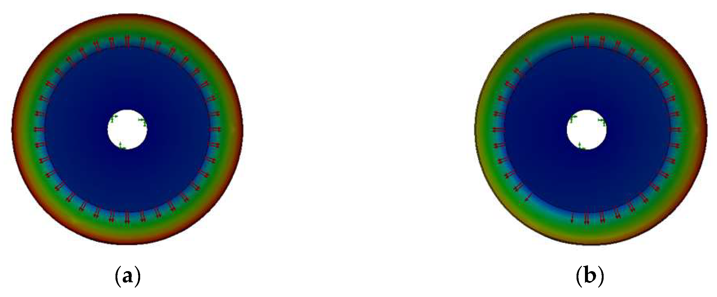
Figure 3.
Rotor disc structure models highlighting deflection for (a) Mode 0 (uniform deflection) and (b) Mode 1 (eccentricity).
The area of the rim is apportioned into 36 parts. The force for each span of β = 10 degrees is applied as shown in Figure 2d. Table 1 illustrates the characteristics of the machine used in the analysis. It is based on the direct-drive permanent magnet machine in [10].

Table 1.
Case study generator data.
The force caused by the normal component of Maxwell stress will be calculated analytically in Section 3.2. So as to develop this model, it was considered the effective magnetic airgap clearance. This means that the changes in stiffness are correlated to the alterations in the size of the airgap. Therefore, expressions describing the airgap behaviour of electrically excited wound rotor machines and permanent magnet generators needed to be produced. Equation (8) is suitable for computing the airgap stiffness for electrically excited generators,
where is the airgap size, whereas Equation (9) should be used in the case of having a permanent magnet machine (with surface-mounted magnets),
where hm is the height of the magnet and μr is the relative permeability of the magnetic material. By introducing these two parameters into the equation, the fact of having surface-mounted permanent magnets can be considered. To evaluate the stiffness of both types of machines for different deflection modes, δ can be substituted by , which would give us the following:
2.3. Overall Stiffness
As said, in order to keep the integrity of the electrical machine, the airgap must remain open and stable. For this, it is necessary that the magnetic force ‘FM’ and the structural force ‘Fs’ equal and opposite. If Equation (7) is manipulated, in Equation (11) it can be seen that the equivalent structural stiffness of the system must be equal (and opposite in sign) to the airgap magnetic stiffness:
where the structural stiffness ‘ks’, will be calculated using finite element techniques.
3. Magnetic Airgap Stiffness
The concept of magnetic airgap stiffness was introduced in Section 2.2. The need for a versatile and quick model that can accurately predict the required magnetic stiffness in several dimensions for different types of machines has led the authors to create a 2-dimensional parametric model that can be used for optimisation purposes. Equations will be developed here for the airgap closing force per unit area as a function of deflection and angle for both wound rotor and surface-mounted permanent magnet machines. Finally, the formulations for the magnetic airgap stiffness will be developed.
Deflection can be different at distinct zones of the rotor and stator [13]. Airgap collapse can take place due to the following:
- Mode 0: Radial expansion of the rotor or radial compression of the stator.
- Mode 1: Rotor eccentricity (localised deflection).
- Mode 2: Distortion of either or both of the circular surfaces into ellipses.
- Mode 3: Distortion with ripples around the circumferences.
The magnetic airgap stiffness expressions for both the wound rotor and the surface-mounted permanent magnet machines will be derived, attempting to address all of these scenarios.
3.1. Airgap Closing Force per Unit Area
Magnetic airgap stiffness arises because of the influence of the airgap clearance on the airgap permeance and hence airgap flux density. This, in turn, affects the airgap closing force. In the case of the airgap closing, the flux density increases and the force per unit area increases. This airgap closing force can be found from the normal component of Maxwell stress σ with Equation (12), where B is the airgap flux density,
and μ0 is the permeability of free space.
The flux density distribution, B, in the airgap can be found as follows:
where is the MMF set up by the rotor field (winding or magnets) and armature windings current and P(θ)/A is the magnetic permeance per unit area. This flux density distribution can be found for a generic machine. Having a pole number of 2p, the main airgap MMF is assumed to be sinusoidally distributed,
Although the airgap flux density distribution for a surface-mounted permanent magnet machine is often more akin to a square or quasi-square wave, Equation (14) is normally a good approximation with , where hm is the magnet height, wm is the magnet height, τp is the pole pitch and μr is relative permeability. It should be noted that because the surface-mounted permanent magnet machine has a larger airgap permeance than conventional salient pole synchronous machines, the MMF per pole will be higher to produce the same flux density (assuming the same number of poles, rating and airgap geometry). Indeed, Equation (13) suggests that for the same airgap flux density, the ratio of MMFs approximates to . This is because the final part of Equation (13) is the magnetic permeance of the airgap. This can be defined in general terms as
where A and l are the cross-sectional area and length of the region in question. Assuming that the iron in the magnetic circuit is infinitely permeable and ignoring slots, then the magnetic permeance reduces to the permeance of the airgap and l = . Before any deflection occurs, the ratio of magnetic permeance of the airgap of the two machines would be
As the deflection occurs, the local airgap changes with the circumferential angle, θ, according to
where and are the nominal airgap clearance. The permeance per unit area can be approximated as
where is the mean value of airgap permeance per unit area and is the amplitude of variation of the airgap permeance per unit area. If δΔ2 terms are neglected, then and . For a surface-mounted permanent magnet machine, the magnetic airgap and airgap clearance are no longer one and the same; the mean and amplitude permeance per unit area terms become and .
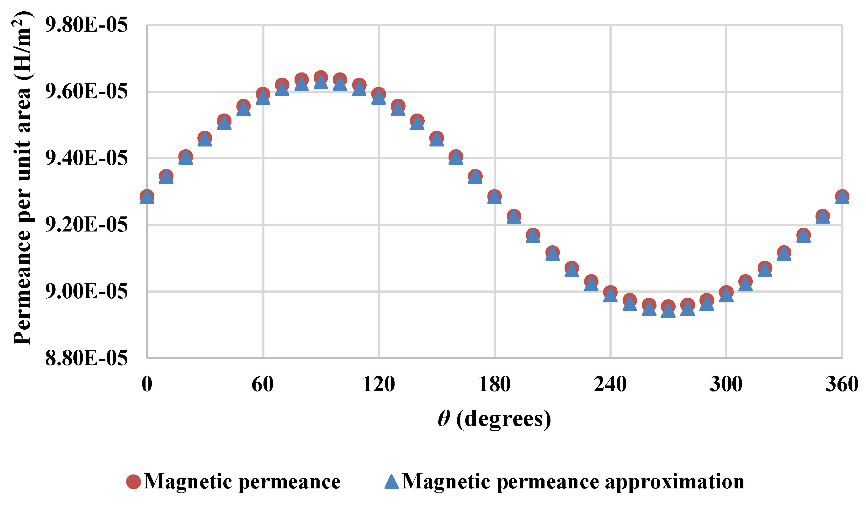
Figure 4 shows a comparison between the outcomes achieved for the magnetic permeance per unit area calculated using Equations (15) and (17) for a permanent magnet machine.
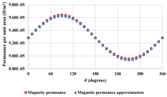
Figure 4.
Magnetic permeance per unit area comparison. Magnetic permeance per unit area vs. magnetic permeance per unit area approximation, assuming infinite permeability for the back iron and ignoring slots.
So as to evaluate the goodness of fit of the magnetic permeance approximation to the magnetic permeance, the normalised root-mean-square error was computed, revealing a value of 1.13% of residual variance. Thus, the permeance approximation calculated using Equation (17) was treated as valid.
Substituting Equations (14) and (17) into (13) and assuming that φ is changed so that peak deflection is at θ = π/2, then it is found that
Equation (18b) is the corresponding equation but for the permanent magnet machine,
Here, there are two spatial frequencies: a high frequency, p, corresponding to the pole pairs and a lower frequency, n, corresponding to the mode of deflection. By substituting (18a) into (12) and rearranging and noting that in the case of many pole pairs, the variation in force distribution due to poles (i.e., the compared cos(pθ)), becomes less significant for structural deflections, then the mean value of cos2(pθ) is ½ and so the stress distribution can be simplified as
For Mode 0 (n = 0), Equation (19a) becomes (19b),
For a surface-mounted permanent magnet machine, the equivalent of Equation (19a) becomes (20a), whereas (19b) becomes (20b) for Mode 0,
Figure 2c illustrates how the magnetic stress varies with angle for different deflection modes in a permanent magnet electrical machine.
To find the force on the rotor or stator surface closing the airgap, Equation (19a) can be integrated over the axial length of the machine, ls, and over any angle, ‘β’. To find the force over an angle β, we can integrate half an angle on either side of the value of θ. For a wound rotor machine, the radial force on an arc of span β centred at angle θ for Modes 1, 2, 3 and 4 is as follows:
with equal to
While for Mode 0 it is
For a surface-mounted PM machine, the radial force on an arc of span β centred at angle θ for Modes 1, 2, 3 and 4 is
with being
Whereas for Mode 0 it is
The magnetic stiffness of the same arc for Modes 1, 2, 3 and 4 of a wound rotor machine can be calculated using the following equation:
For Mode 0, the stiffness would be computed using Equation (23b)
The magnetic stiffness of the said arc is for Modes 1, 2, 3 and 4 of a PM machine equal to
whereas for Mode 0 it is
3.2. Validation Using Finite Element Code
Finite element analysis of a two-pole model was used to validate the analytical models for airgap closing force and stiffness.
This was carried out using the 2D code FEMM [14], meaning that any variations in the third (axial) dimension are neglected. This matches the analytical model where the axial dimension is also neglected. Generally speaking, a 3D model would show a reduction in radial airgap flux density at the ends of the machine as some flux leaks into the axial direction. This is likely to mean that the airgap closing forces predicted by 2D finite element analysis are likely to be slightly higher than for the 3D code and a real machine. These differences are likely to be small when the axial length is large (here, ls = 1.2 m). The choice of 2D code also means that any variations in the axial deflection are neglected. This is consistent with all the models presented here in this paper.
To make the model more versatile, the two-pole model has been geometrically linearised so that radial lines and arcs are mapped onto vertical and horizontal lines, respectively. By changing the airgap clearance by a deflection δ, a number of magnetostatic runs were processed, and the results were interrogated to find the airgap closing force. Using a force via a weighted stress tensor approach, the obtained results are shown in Figure 5, where the force is plotted against deflection δ.
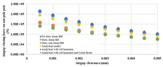
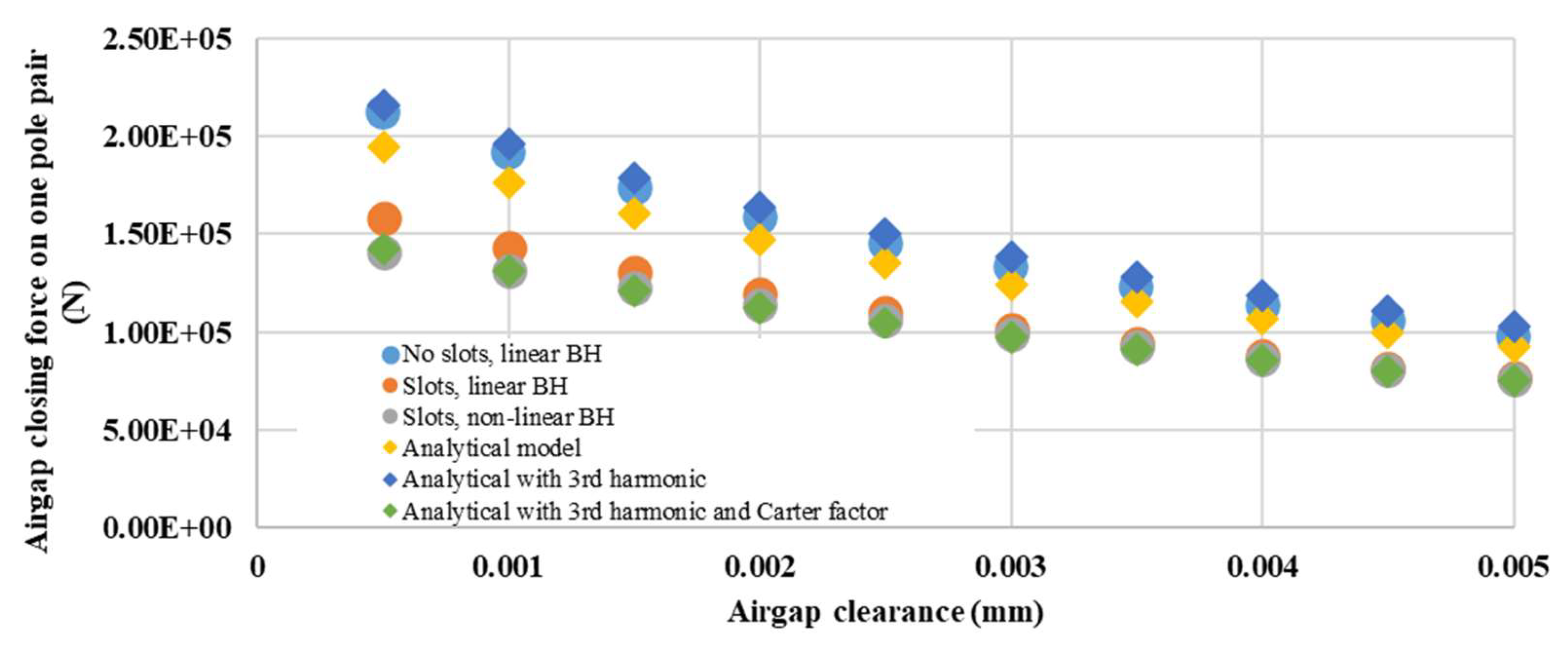
Figure 5.
Magnetic airgap stiffness for a pole pair of a PM generator for a direct-drive wind turbine, based on [13]. Airgap closing force on one pole pair vs. airgap clearance.
There are three FE cases: (i) where the materials are assumed to have linear BH curves and the stator has no slots (similar to the analytical model); (ii) where slotting is introduced but the materials have linear BH curves and (iii) where slotting is present and non-linear BH curves are used.
Also, in Figure 5 one can see the analytical solutions for the same dimensions and materials using Equation (22a) for δ∆ = 0 and and one pole pair (i.e., ).
The analytical model clearly underestimated the force; this can be seen when comparing the results with those of the idealised FE model (i). This suggests that only using the fundamental MMF as an input to the analytical solution is incorrect as it leads to the model neglecting higher-order airgap flux density spatial harmonics and the resulting force contributions. The MMF of a surface-mounted permanent magnet of width can be written as follows:
where m is the harmonic order. Including m = 1 and m = 3 in Equations (21) and (22) leads to the amended force equation of
This has been plotted in Figure 5. This shows better agreement with the idealised FE results (i). When slotting is introduced (FE models (ii) and (iii)) there is a noticeable reduction in force. The analytical model ignores the reduction in permeance due to slotting. This can be taken into account by applying the Carter factor to the effective magnetic airgap, in other words,
The results for Equation (27) are plotted in Figure 5 and show good agreement with the FE models (ii) and (iii). The difference between linear and non-linear materials is relatively modest if the magnetic circuit is designed to avoid saturation in the default state.
4. Case Study Generator
Magnetic stiffness and structural stiffness are brought together in this section in order to study a 3 MW wind turbine generator. By assuming a deflection, the closing force acting on the airgap can be estimated making use of the magnetic model and utilised to calculate the structural deflection through a structural model. The characteristics of the electrical machine used in this analysis are displayed in Table 1 located in Section 2.2.
As explained, the required stiffness for the generator structure can be computed in different ways. In this case, a structural finite element model of the generator was created in SolidWorks.
For the FE model, the rotor and the stator structures were loaded with radial stresses which were calculated as explained in the previous subsection using the data presented in Table 1 and a mean deflection, ‘’, of 1 mm and variable deflection, ‘’, of 0.5 mm. The cylindrical sub-structures of both the rotor and the stator were apportioned into 36 parts so that the appropriate forces corresponding to Modes 0, 1, 2, 3 and 4 could be applied. With this, the deflection experienced by the structure was found, allowing the structural stiffness of the generator to be evaluated.
The structural radial deflection of each 10-degree part was measured making use of deflection sensors located on the outer face of each part in the case of the rotor and on the inner face in the case of the stator.
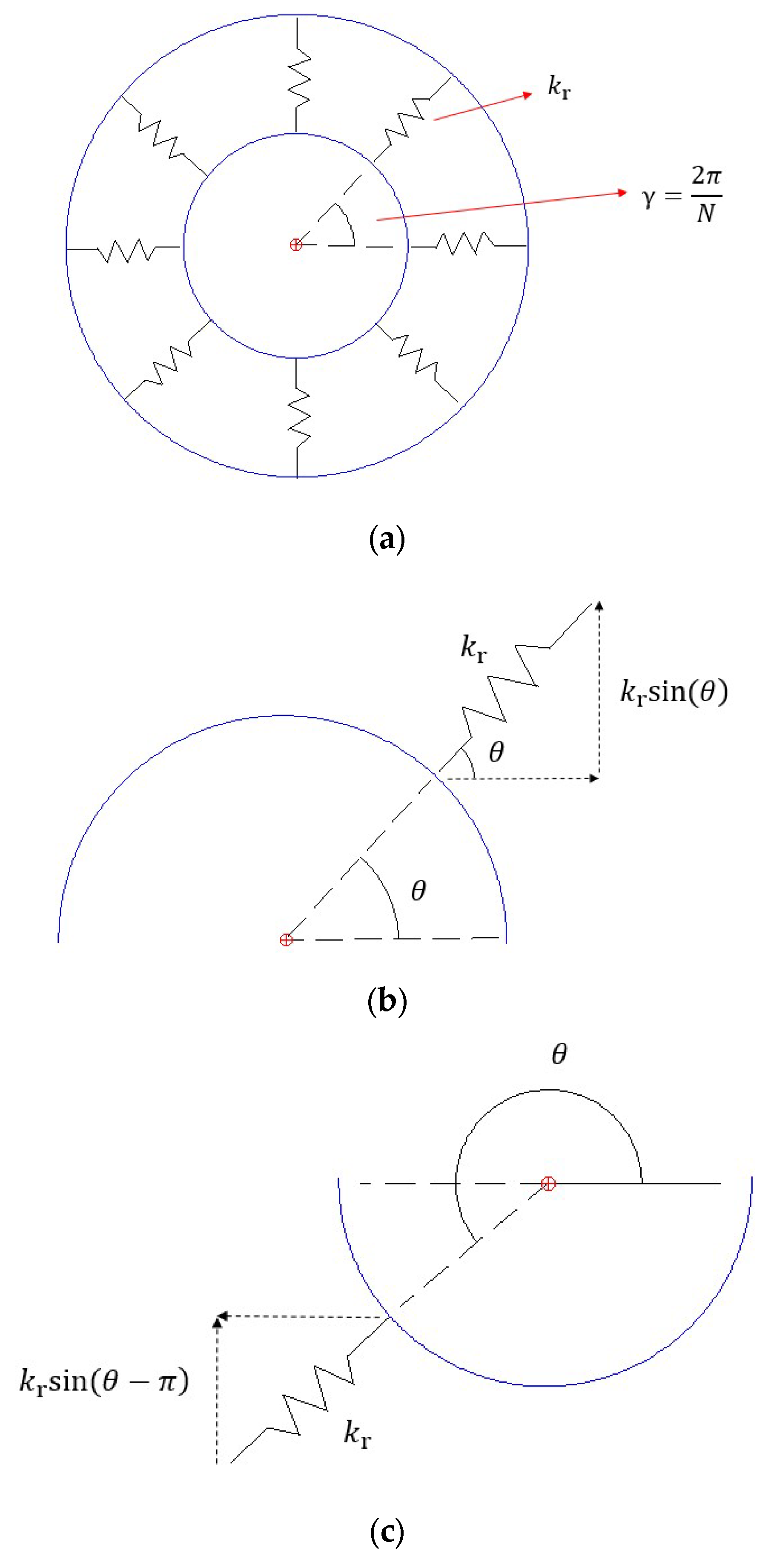
So as to know if the structure will be able to resist the load, the absolute value of the magnetic stiffness estimated using the analytical model must be equal to or smaller than the structural stiffness calculated with the finite element study. This means that . Combining the stiffnesses of the bearing, the rotor and the stator in series, the total stiffness of the generator structure is assessed. The bearing stiffness is assumed to be constant with a value of 3 × 10⁹ N/m. In order to calculate the equivalent stiffness for each 10-degree part, the bearing has been modelled as a finite number of radial stiffnesses set in parallel as shown in Figure 6a, where kr corresponds to the radial stiffness, γ is the angle between stiffnesses and N is the total number of radial stiffnesses, in our case 36.
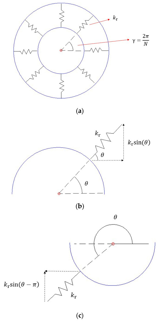
Figure 6.
(a) Bearing model showed as stiffness. Bearing structure split into top and bottom parts: (b) top part; (c) bottom part.
Paying special attention to Mode 1, where a force F is applied to the top of the structure generating a deflection δ, which gives a stiffness kb = F/δ, the bearing has been split into a top structure and a bottom structure as depicted in Figure 6b,c. The total stiffness of the top structure kT, can be calculated using Equation (28a), where the vertical components of all the radial stiffnesses in the top structure, in this case 18, are added up. Similarly, the stiffness of the bottom structure kB can be estimated by making use of Equation (28b). It is assumed that under Mode 1 deflection, the top bearing structure is under tension, whereas the bottom part works under compression.
Thus, the total stiffness ‘kb’, can be computed as follows:
From the relation
then
Finally, considering the identity
and rearranging Equation (31), it can be obtained that the stiffness for each 10-degree section is
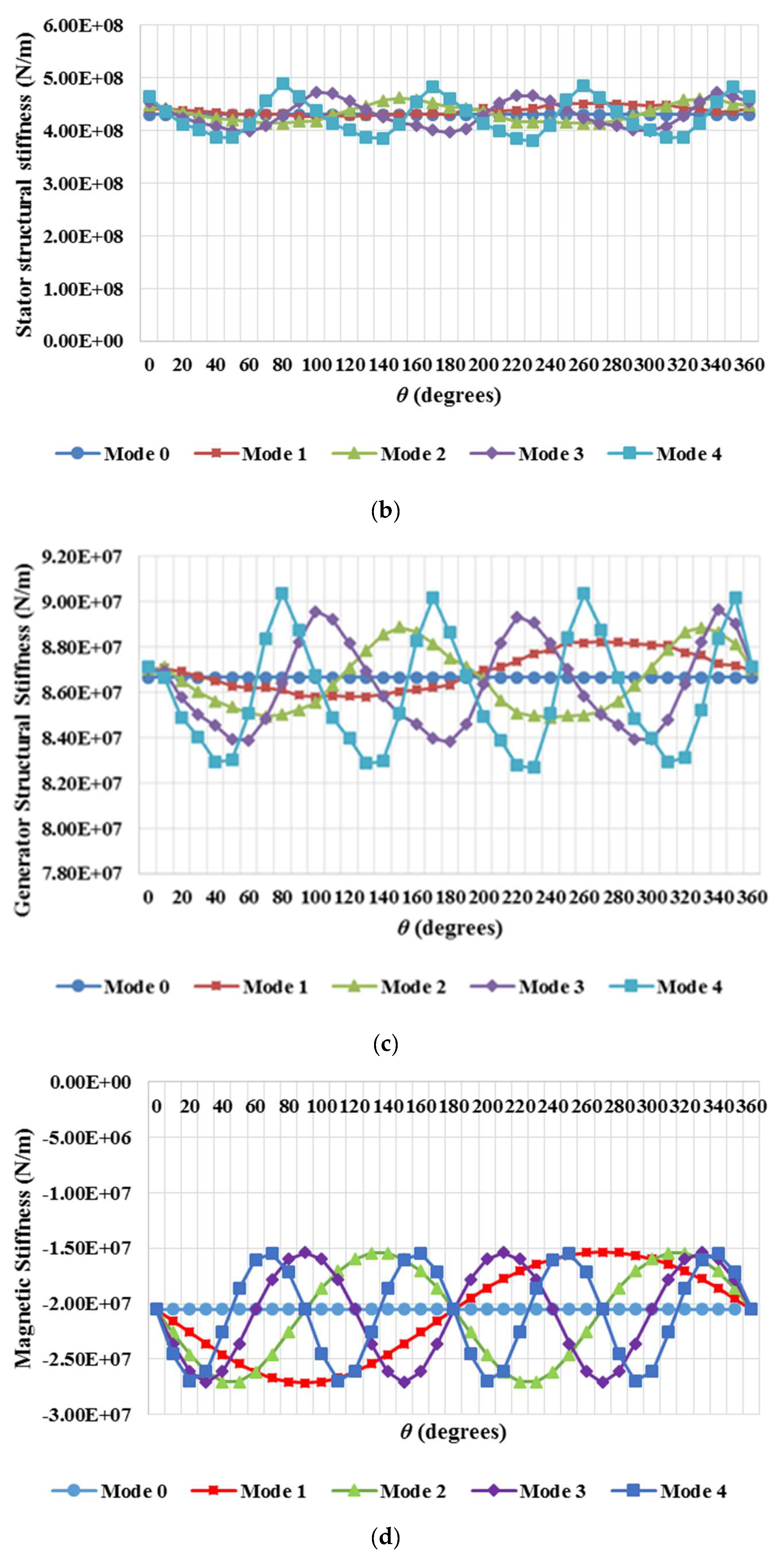
In this case, with N equal to 36, kr shows the value of 1.31 × 10⁸ N/m. Figure 7a–d present the results acquired for the rotor and stator structures utilising the FE model, the results of combining the structures in series and the magnetic stiffness on each beta degree section.
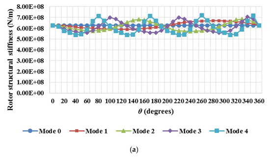
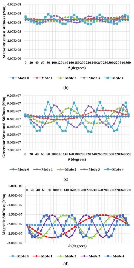
Figure 7.
(a) Rotor structural stiffness for deflection modes ranging from 0 to 4 vs. Theta; (b) stator structural stiffness vs. Theta; (c) generator structural stiffness vs. Theta; (d) magnetic stiffness on beta degree section.
Figure 7c gives the results of combining the structures in series as mentioned. As seen, Mode 4 shows the worst performance with a minimum stiffness of 8.27 × 10⁷ N/m. Mode 4 also presented the worst results for the compliant structure with a minimum generator stiffness of 6.94 × 10⁷ N/m. If these data are compared to those achieved for the necessary magnetic stiffness introduced in Figure 7d, it can be seen that the structural stiffness is higher than the magnetic stiffness, with the results achieved for the stiff generator structural stiffness varying about 8.7 × 10⁷ N/m, and about 7.4 × 10⁷ N/m for the compliant structure, and the stiffness for each 10-degree β section around −2 × 10⁷ N/m.
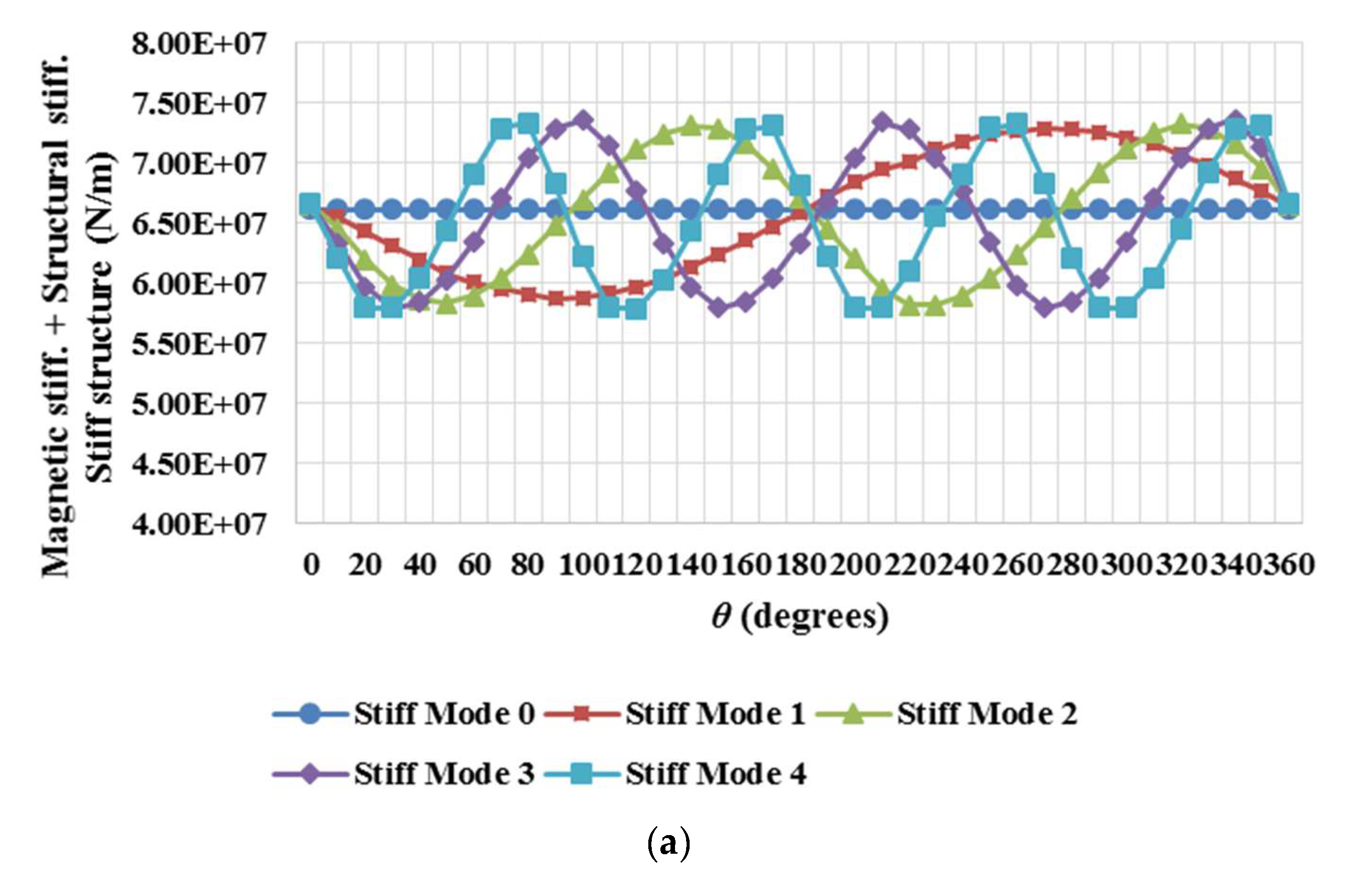
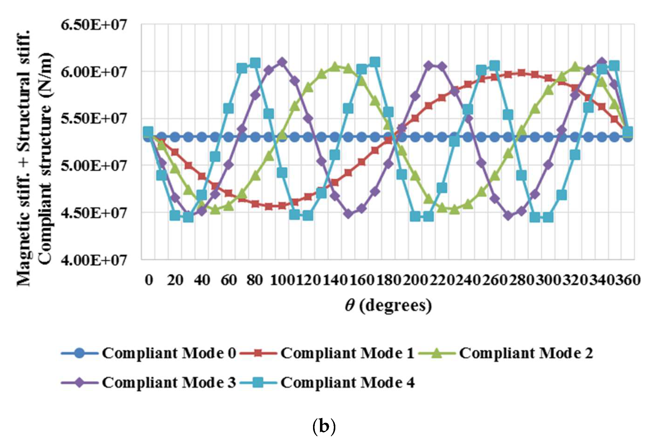
In Figure 8a, the combination of magnetic stiffness and structural stiffness is plotted against the angle for each deflection mode. Four distinct scenarios have been analysed in order to identify the mode giving the lowest value. With going from 1 mm up to 4 mm in steps of 1 mm and taking 0.5 mm, 0.75 mm and 1 mm values, all the options have been addressed. See Table 2. Since the structural geometry and material are the same, it was assumed that the generator structural stiffness should be invariant with angle, ‘θ’, and mode, ‘n’, for all scenarios. Mode 4 showed the most unstable behaviour with the lowest stiffness at 4.73 × 10⁸ N/m, as can be observed in Table 2, where the lowest stiffnesses acquired for each mode and case are illustrated.
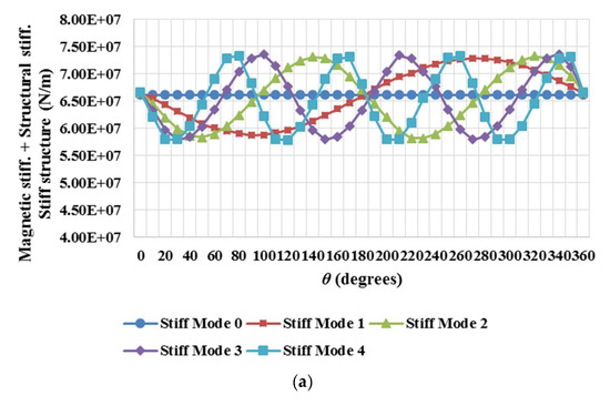
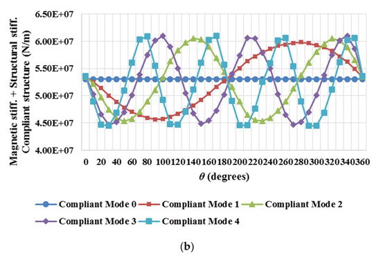
Figure 8.
Overall stiffnesses comparison: (a) stiff structure; (b) compliant structure.
Table 2.
Minimum structural stiffness per case and mode.
If cases 1 and 3 are compared, it can be seen that an increment of 1 mm in variable deflection corresponds to a drop in the minimum stiffness of about 16%. If cases 2 and 4 are contrasted, it can be observed that an increase of 3 mm in mean deflection represents a decrease in the minimum stiffness of about 5%. This demonstrates that both deflections exert an influence of different weights over the stiffness of the generator structure.
By looking at Figure 8a, one can appreciate that for the worst-case scenario, which corresponds to the collapse of the airgap with the stator structure physically touching the magnets, the mode presenting the worst performance is Mode 4, having the lowest stiffness value at 5.79 × 10⁷ N/m.
It was observed that the structure selected for the study was very stiff and it is rather difficult to appreciate the overall impact of the magnetic stiffness even in the worst-case scenario. By carrying out a considerable reduction in the thickness of both disc and rim sub-structures of the rotor and the stator, a more compliant structure was generated for its study. With higher magnetic stiffnesses, lower overall stiffnesses are achieved and it is expected to see that at some point the total stiffness reaches zero values. The thicknesses used for both analyses are given in mm in Table 3.
Table 3.
Thicknesses for stiff and compliant structures.
A drop in the rotor and the stator masses of 27% and 31%, respectively, was obtained. This corresponds to a total mass loss of 30%, which corresponds in this case to an overall stiffness reduction of 21%. The equivalent rotor stiffness average for this structure was about 4.6 × 10⁸ N/m, whereas the stator stiffness was around 2.6 × 10⁸ N/m.
In Figure 8a,b, a comparison between the stiffnesses for each mode and for each structure is displayed. As observed, a drop in the minimum value of the overall stiffness of more than 1 × 10⁷ N/m is achieved. The reduction in thickness of each sub-structure forming the machine revealed a substantial drop in stiffness for this permanent magnet generator. This shows the effect of compliant (lighter) structures and how the approach can be used in the design process.
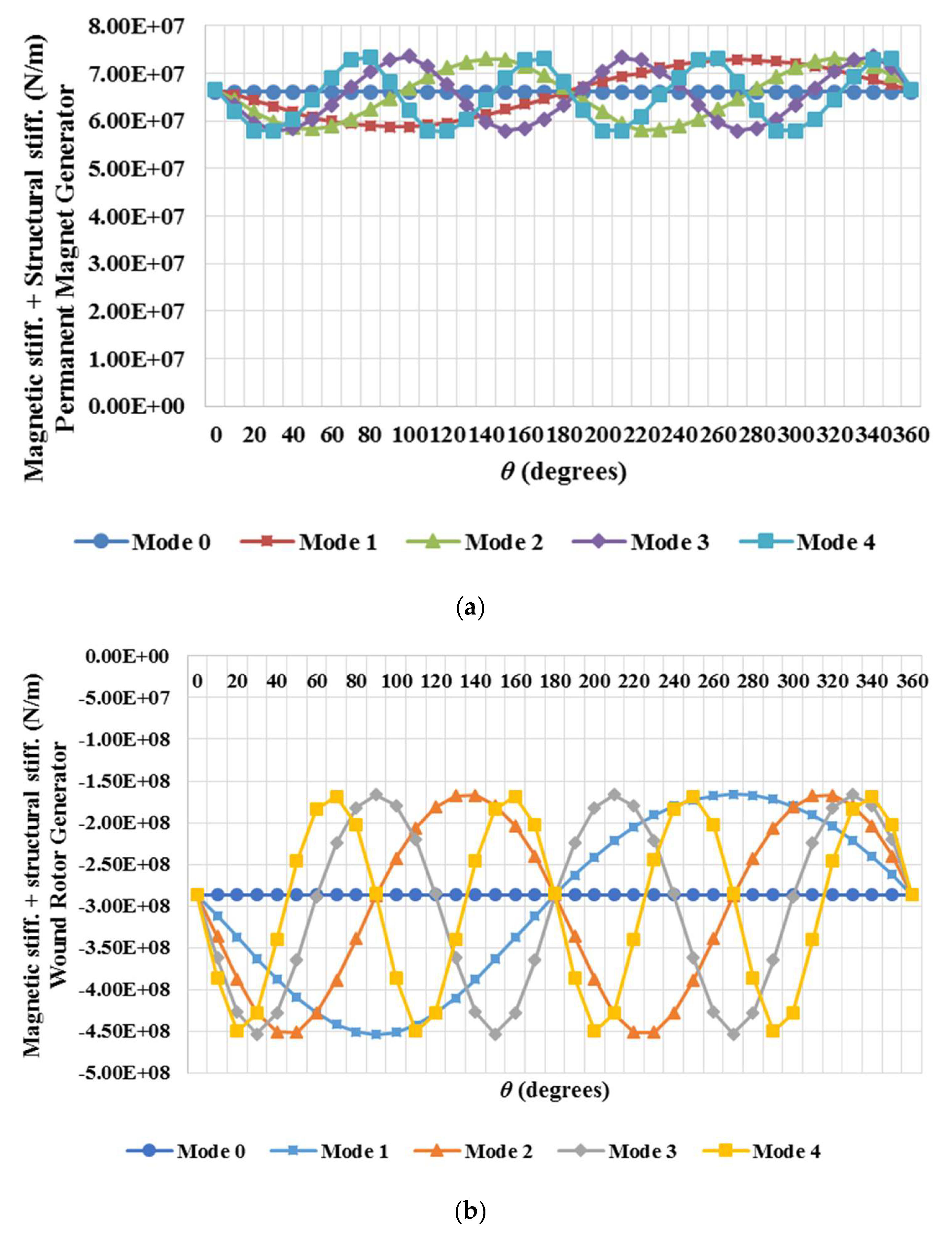
With both structures fully described and analysed for the PM machine, the stiff structure was studied under the demanding loading conditions of a wound rotor machine. Since the effective airgap size of a wound rotor machine is smaller than that of a PM generator due to the lack of magnets attached to the rotor surface, the forces are one order of magnitude larger in all cases and for all the modes. As predicted, the effect of the large increase in magnetic stiffness produced a very significant drop in the overall stiffness, as seen in Figure 9b.
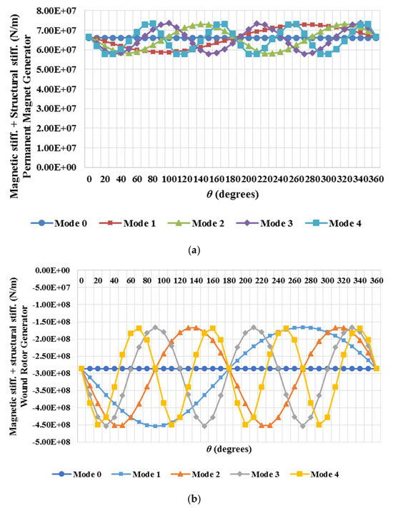
Figure 9.
Magnetic stiffness + structural stiffness vs. Theta; (a) permanent magnet generator; (b) wound rotor generator.
The negative values for the minimum stiffness mean that the structure is not stiff enough to resist the loads and the airgap would close.
5. Discussion
Various approaches exist in order to design a supporting structure for a wind turbine electrical generator capable of withstanding the loads. A stiffness model joining the magnetic and the mechanical designs has been developed. The 2D magnetic model assumes a uniform radial deflection, ‘’, and a variable deflection, ‘’, that changes with angle, to estimate the resulting airgap closing force under different modes of deflection. The assumed deflection and the obtained force are then utilised to calculate the airgap stiffness. At this point, a structural model was created and making use of the computed loads, a set of finite element analyses was run for a 3 MW machine with a simplified steel structure made with discs. With the deflection, the structural stiffness of the machine could be approximated. A comparison was undertaken between the airgap stiffness from the magnetic model, the structural stiffness and what the stiffness margin was.
The magnetic model for the airgap closing force and stiffness of a PM machine was validated using a 2D finite element code. A two-pole model with periodic boundaries, neglecting axial effects and geometrically linearised so that radial lines and arcs are mapped onto vertical and horizontal lines, was produced to carry out the task. Three finite element cases were generated: (i) the stator has no slots and the materials have a linear BH behaviour; (ii) the stator has slots and the materials have linear BH curves and (iii) the stator has slots and the materials have no linear BH curves. Comparing the analytical model with the idealised FE model (i), it could be observed how the analytical model underestimated the force. It was proven that the use of the fundamental MMF only leads to neglecting higher-order airgap flux density spatial harmonics and the resulting force contributions. With that, the analytical model was amended to incorporate the 3rd harmonic, achieving better results. Nevertheless, the model did not take into consideration the slotting that, according to the FE models (ii) and (iii), significantly reduced the forces. So as to replicate this behaviour, the Carter factor was introduced into the analytical model. A good agreement was achieved; hence, the magnetic model was considered valid.
Two distinct types of generators were analysed: a permanent magnet machine and a wound rotor machine. It was found that a stiffer and more robust structure is necessary for a wound rotor machine, which in turn leads us to have a heavier generator. It is also necessary to highlight the fact that the magnetic design of a PM machine can be designed to avoid saturation in the default state, while when a wound rotor machine airgap closes, the iron parts of the magnetic circuit go deep into saturation, bringing about significant reluctance.
As mentioned, the magnetic study of both machines was completed first assuming a uniform radial deflection and variable deflection which changes with angle, ‘θ’. Looking at the results obtained for both cases, their effects on the magnetic, structural and overall stiffnesses can be understood. The increase in supposes a noticeable decrease in the absolute values of the maximum and minimum magnetic stiffness, whereas the increment in force as the airgap closes causes a substantial reduction in the structural stiffness that puts down the overall stiffness. If is augmented, the absolute value of the maximum magnetic stiffness increases while the minimum stays at the same level. The structural stiffness diminishes, and the overall stiffness affected by the increase in the magnetic stiffness and the drop in the structural stiffness goes down although it never reaches a zero value, which means that the structure is eventually very stiff, and it would easily support the imposed loading conditions. A more compliant structure was also looked at. A total reduction in mass of 30% was accomplished. That meant a decrease of 27% in rotor mass and 31% in stator mass. After the analysis, it could be observed that the drop in mass corresponded to a decrease in the overall stiffness of 21%. This gives a clear picture of the trade-off process that should be made during an optimisation study.
Mode number was another factor that had a significant impact on the distinct stiffnesses. In the case of the magnetic stiffness, it could be seen that despite having different spatial frequencies, all the modes but Mode 0 shared the same maximum value. Mode 0 appeared as a straight line (due to its constant uniform load applied), coinciding with the inflexion points of the curves corresponding to the rest of the modes. Similar behaviour was noticed for the structural and overall stiffnesses, although in the case of the structural stiffness, Mode 4 stood out, showing the worst performance with the minimum stiffness at 8.27 × 10⁷ N/m for the stiff structure and 6.94 × 10⁷ N/m for the compliant structure. It is not clear whether this is a general result or rather an artefact of the discretisation of the structures into 36 regions. It is also worth noting that in real machines, the initial airgap deflections are usually of lower orders, e.g., Mode 0, 1 and 2 [10].
In terms of use, this model can be utilised during the design stage but also after manufacturing and during operation as part of an online airgap condition monitoring system. Post-manufacturing measurements can be used to determine which modes of airgap deformation will be problematic. The model would be able to predict the airgap behaviour and its suitability for operation. As part of a condition monitoring system, the model would be capable of evaluating the time-varying output data and assessing the structural integrity of the machine.
6. Conclusions
A stiffness model coupling the electromagnetic and mechanical designs of electrical machines has been developed. The results of the validation with the FE model showed the usefulness and accuracy of the magnetic analytical tool. In addition, the parametric nature of this analytical model makes it easy to use, helping the designer carry out quick estimations for any deformation mode and magnitude, in the early stages of the design or after the manufacturing process. It could also be useful for optimisation purposes, leading to more sustainable designs or as part of an online condition monitoring system as it could assess the structural integrity of the machine at any time. The model is ready and validated through finite element means. Due to its simplicity, the authors believe that its implementation in an existing system will not require a significant effort.
The major insight from the magnetic stiffness model is that the inherent reluctance of the permanent magnet reduces the magnitude of the stiffness that the structure must fulfil. In terms of airgap closing, wound rotor machines need to be stiffer than permanent magnet machines—and subject to the same mechanical design approach and materials—therefore, heavier. The analysis shows that the modes of deflection higher than Mode 0 (uniform deflection) lead to more severe stiffness requirements for the structure. This implies that these modes should be used in any structural analysis, in addition to or instead of Mode 0.
Regarding the mechanical model, the results show that higher modes of deflection can lead to stiffness varying circumferentially. It is the coincidence of the extremes in the magnetic and structural stiffness profiles that can lead to a small or negative stiffness margin, as opposed to the average magnetic and structural stiffness values.
Further steps to develop this approach include extending the magnetic analytical modelling into the third, i.e., axial dimension, thereby allowing axis tilt and bowing/sagging modes of deflection to be considered. The discretised structural approach here introduces some uncertainty into the modelling of structural stiffness profiles, particularly for higher modes. This could be addressed through analytical approaches or by using a larger number of discrete zones in the finite element model.
Author Contributions
Conceptualisation, A.M. and P.J.-S.; methodology, A.M. and P.J.-S.; software, A.M. and P.J.-S.; validation, A.M. and P.J.-S.; formal analysis, A.M. and P.J.-S.; investigation, A.M. and P.J.-S.; data curation, A.M. and P.J.-S.; writing—original draft preparation, A.M. and P.J.-S.; writing—review and editing, A.M. and P.J.-S.; visualisation, A.M. and P.J.-S.; supervision, A.M.; project administration, A.M. All authors have read and agreed to the published version of the manuscript.
Funding
This research received no external funding.
Institutional Review Board Statement
Not applicable.
Informed Consent Statement
Not applicable.
Data Availability Statement
Data is contained within the article.
Acknowledgments
We would like to thank David Infield and Ozan Keysan from the Electronic and Electrical Engineering departments of the University of Strathclyde, in Glasgow (UK), and the Middle East Technical University, in Ankara (Turkey), respectively, for providing valuable feedback on this article.
Conflicts of Interest
The authors declare no conflicts of interest.
Nomenclature
| A | Area, m2 |
| B | Magnetic flux density, Wb/m2 |
| Bg | Peak flux density in the airgap, T |
| F | Force caused by the normal component of the Maxwell stress, N |
| Fc | Airgap closing force, N |
| FPM | PM machine radial magnetic force, N |
| FWR | Wound rotor machine radial magnetic force, N |
| Magnetomotive force, At | |
| Peak magnetomotive force, At | |
| Peak magnetomotive force calculated with analytical model, At | |
| Peak magnetomotive force calculated with analytical model including third harmonic, At | |
| Peak magnetomotive force for a permanent magnet machine, At | |
| Stiffness of component A, N/m | |
| Stiffness of component B, N/m | |
| Bearing stiffness, N/m | |
| Carter factor | |
| Equivalent stiffness, N/m | |
| Equivalent rotor stiffness, N/m | |
| Magnetic stiffness, N/m | |
| PM generator magnetic stiffness, N/m | |
| Generator structure stiffness, N/m | |
| Rotor structure stiffness, N/m | |
| Stator structure stiffness, N/m | |
| Total stiffness of the top structure, N/m | |
| WR generator magnetic stiffness, N/m | |
| l | Axial length of machine, m |
| N | Total number of bearing radial stiffnesses |
| n | Deflection mode |
| Mean value of airgap permeance per unit area, H/m2 | |
| Amplitude of variation of the airgap permeance per unit area, H/m2 | |
| p | Number of pole pairs |
| Variable used to simplify Equation (21b) | |
| Variable used to simplify Equation (22b) | |
| β | Span angle, degrees |
| Angle between bearing radial stiffnesses, degrees | |
| δ | Deflection, m |
| δr | Rotor deflection, m |
| δs | Stator deflection, m |
| δStructural | Structural deflection, m |
| Mean deflection, m | |
| Deflection change respect to the mean, m | |
| ε | Mechanical strain |
| θ | Pitch or circumferential angle, degrees |
| μ0 | Permeability of free space, 4 × 10⁻⁷ H/m |
| μr | Relative permeability |
| σ | Structural stress, Pa |
| Stress during operation in permanent magnet machine, Pa | |
| Stress during operation in wound rotor machine, Pa | |
| Phase angle, degrees |
References
- Kumar, R.; Singh, S.; Srivastava, R.; Saket, R. Dynamic reluctance air gap modeling and experimental evaluation of electromagnetic characteristics of five-phase permanent magnet synchronous generator for wind power application. Ain Shams Eng. J. 2020, 11, 377–387. [Google Scholar] [CrossRef]
- Odeh, M.; Mohsin, K.; Ngo, T.; Zalkind, D.; Jonkman, J.; Wright, A.; Robertson, A.; Das, T. Development of a wind turbine model and simulation platform using an acausal approach: Multiphysics modeling, validation, and control. Wind Energy 2023, 26, 985–1011. [Google Scholar] [CrossRef]
- He, X.; Geng, H.; Mu, G. Modeling of wind turbine generators for power system stability studies: A review. Renew. Sustain. Energy Rev. 2021, 143, 110865. [Google Scholar] [CrossRef]
- Polinder, H.; Van der Pijl, F.F.; De Vilder, G.J.; Tavner, P.J. Comparison of direct-drive and geared generator concepts for wind turbines. IEEE Trans. Energy Convers. 2006, 21, 725–733. [Google Scholar] [CrossRef]
- Bywaters, G.; John, V.; Lynch, J.; Mattila, P.; Norton, G.; Stowell, J.; Salata, M.; Labath, O.; Chertok, A.; Hablanian, D. Northern Power Systems WindPACT Drive Train Alternative Design Study Report; NREL: Golden, CO, USA, 2004. [Google Scholar]
- Grauers, A. Design of Direct-Driven Permanent-Magnet Generators for Wind Turbines. Ph.D. Thesis, Chalmers University of Technology, Gothenburg, Sweden, 1996. [Google Scholar]
- Versteegh, C. Low speed direct drive PM generator for application in the Zephyros Z72 wind turbine. In Proceedings of the IEE Seminar on Electrical Aspects of Offshore Renewable Energy Systems (NAREC), Blyth, UK, 24–25 February 2004. [Google Scholar]
- McDonald, A.S. Structural Analysis of Low Speed, High Torque Electrical Generators for Direct Drive Renewable Energy Converters. Ph.D. Thesis, University of Edinburgh, Edinburgh, Scotland, 2008. [Google Scholar]
- Stander, J.N.; Venter, G.; Kamper, M.J. Review of direct-drive radial flux wind turbine generator mechanical design. Wind Energy 2012, 15, 459–472. [Google Scholar] [CrossRef]
- Jaen-Sola, P. Advanced Structural Modelling and Design of Wind Turbine Electrical Generators. Ph.D. Thesis, University of Strathclyde, Glasgow, Scotland, 2017. [Google Scholar]
- Klinger, F.; Müller, L. State-of-the-Art and New Technologies of Direct Drive Wind Turbines. In Towards 100% Renewable Energy; Uyar, T., Ed.; Springer: Berlin/Heidelberg, Germany, 2017; pp. 33–50. [Google Scholar]
- Zavvos, A. Structural Optimisation of Permanent Magnet Direct Drive Generators for 5MW Wind Turbines. Ph.D. Thesis, University of Edinburgh, Edinburgh, Scotland, 2013. [Google Scholar]
- Tavner, P.J.; Spooner, E. Light Structures for Large Low-Speed Machines for Direct-Drive Applications. In Proceedings of the International Conference on Electrical Machines, Chania, Greece, 2–5 September 2006. [Google Scholar]
- FEMM ‘Finite Element Method Magnetics’. Available online: www.femm.info/ (accessed on 12 January 2024).


Disclaimer/Publisher’s Note: The statements, opinions and data contained in all publications are solely those of the individual author(s) and contributor(s) and not of MDPI and/or the editor(s). MDPI and/or the editor(s) disclaim responsibility for any injury to people or property resulting from any ideas, methods, instructions or products referred to in the content. |
© 2024 by the authors. Licensee MDPI, Basel, Switzerland. This article is an open access article distributed under the terms and conditions of the Creative Commons Attribution (CC BY) license (https://creativecommons.org/licenses/by/4.0/).