1. Introduction
1.1. Research Background
In recent years, with the rapid development of science and technology, the electronic equipment that runs through our daily life is constantly being updated. Currently, the developmental trend of electronic equipment is miniaturization, portability and multi-functionality. However, in order to load more functions into a smaller volume, a high degree of integration within the equipment is inevitable, which means that during the operation of the equipment, more heat loads are generated in a smaller heat dissipation space, which undoubtedly greatly increases the risk of equipment failure or even damage due to overheating. The increase in heat load of equipment is essentially an increase in the technical requirements for heat dissipation, but when choosing heat dissipation technology, we should not only consider the heat dissipation ability but also consider the corresponding cost, so, at present, how to dissipate heat efficiently and cheaply is a big threshold for the development of electronic equipment [
1,
2,
3].
The existing cooling methods can be divided into two categories: active cooling and passive cooling. Forced convection, spray cooling and jet cooling all belong to active cooling [
4,
5]. Both jet cooling and spray cooling need a variety of supporting devices such as nozzles, and the sprayed cooling working medium cannot be recovered in complex small electronic equipment [
6]. Forced convection needs pumps to maintain, and it is difficult for small electronic equipment to carry suitable pumps, while large electronic equipment needs to carry a large number of high-power pumps, which is obviously uneconomical. Compared with passive cooling, although the heat dissipation capacity of active cooling is improved, it needs external energy input to maintain it, and at the same time, it needs more complicated supporting equipment, which is inconsistent with the current development trend and heat dissipation demand of electronic equipment [
7,
8].
Passive cooling, such as natural convection, does not need an external energy input, but its heat dissipation ability is weak; even if it is improved by physical means, it is still unsatisfactory. However, the heat pipe is different, with its simple structure and excellent heat transfer ability and thermal stability, and it is a good choice when solving the heat dissipation problem [
9,
10].
1.2. Brief Introduction of Pulsating Heat Pipe
Among the heat pipes, the pulsating heat pipe (PHP) is excellent. Compared with the traditional heat pipe, it has no wick, and its structure is simpler. Moreover, it can be bent at will and arranged flexibly. Since it was put forward in the 1990s, it has been the focus of scholars’ research [
11]. Pulsating heat pipes are formed by bending capillaries with extremely small diameters many times, which can be divided into three forms, as shown in the following
Figure 1, namely, the open pulsating heat pipe, the closed-loop pulsating heat pipe and the closed-loop pulsating heat pipe with check valve [
12]. Before operation, the heat pipe needs to be vacuumized. After vacuumizing, the working media are injected by pressure difference. Under the action of capillary force and other forces, the working media partially evaporate and the gas and liquid phases are randomly distributed. The evaporator section absorbs heat to increase the pressure and push the working media to flow to the condenser section. The condenser section receives cryogenic energy to reduce the pressure, and the formed internal pressure difference in the pipe pushes the working media to circulate continuously, thus realizing heat transfer.
The introduction of pulsating heat pipes in the field of thermal management can not only meet the severe challenge of heat dissipation but also have a positive impact on the sustainable development of resources and the economy. Pulsating heat pipes, as a passive heat dissipation technology, have low cost, which can significantly reduce the economic consumption of users and increase the net benefit. In addition, because the pulsating heat pipe does not need an external energy input, it can not only reduce energy consumption but also collect heat for other purposes through internal circulation, realize energy recovery and reuse and promote the sustainable development of economy and energy.
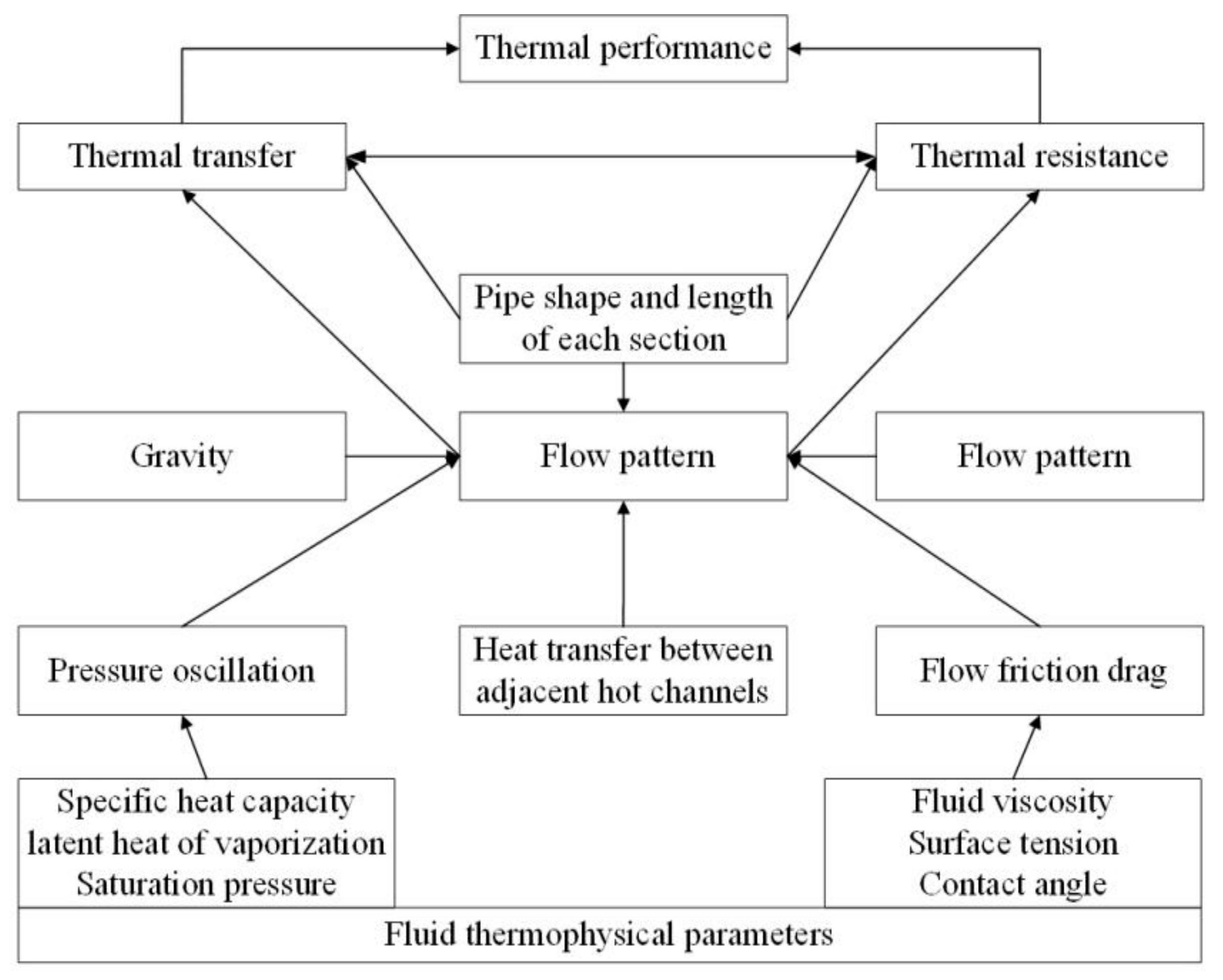
The structure and usage of a pulsating heat pipe are not complicated, and the driving force of operation is only the change in temperature and pressure, but the relationship between the parameters and the temperature or pressure is not simple. This is not only due to the influence of a single parameter but the result of multi-parameter interactions [
13] (
Figure 2).
1.3. Review Methodology
Until now, the specific operation principle has not been fully revealed. Moreover, at present, many reviews on pulsating heat pipes only put forward suggestions for improving the existing parameters but did not put forward new research parameters. In this paper, new heating parameters are put forward after summarizing the existing research. Therefore, this paper summarizes nearly 100 articles on pulsating heat pipes in recent years, such as journals, conferences, dissertations, etc., and provides some reference for future research.
Some references are listed here to show the information, such as the year and type of reference (
Table 1).
2. Working Media
Working media are the carrier of heat circulation in pulsating heat pipes, which affect the thermal performance of pulsating heat pipes through their own thermophysical properties [
17]. Thermodynamic parameters, such as specific heat, boiling point and latent heat of vaporization, which affect the temperature and pressure of a working medium, will have great influence on the thermal performance of a pulsating heat pipe.
Common working medias of pulsating heat pipes are listed here (
Table 2).
The performance of a pulsating heat pipe is usually divided into start-up performance and operation performance. Whether in the start-up process or the operation process, the flow of working media needs to overcome the negative effect of viscosity. The start-up of a pulsating heat pipe means that the working medium in the pipe absorbs heat and pressurizes it, overcomes the negative effect of viscosity and begins to pulsate. Therefore, the gradient of pressure with the increase in temperature is the key factor for start-up [
18].
Although the pulsating heat pipe has excellent heat transfer performance, there are still heat transfer limits. Different working fluids have different maximum heat inputs, temperature fluctuations and thermal resistance changes, which are closely related to the boiling point and latent heat of working fluids [
19,
20] (
Figure 3). Zhang et al. [
21] have studied the influence of working fluid on the performance of a vertically placed plate pulsating heat pipe, and they have pointed out that ethanol and ultra-pure water have smaller heat transfer resistance than methanol under the condition of a small heat input; when the heat input increases, the temperature rises more gently than with methanol.
The study of working fluids is essentially the study of thermal properties. Currently, the research is no longer limited to the comparison of different kinds of pure working fluids, and mixed working fluids are also an important field in the current research. At present, mixed working fluids can be divided into the simple mixing of different pure working fluids and the addition of surfactants or nanofluids. The influence of the simple mixing of pure working fluids on the performance of heat pipes depends on the difference in the physical properties and mixing ratios between different pure working fluids, and the two factors jointly determine which side the thermal properties of mixed working fluids are more like [
22] (
Figure 4).
Surfactants and nanofluids are new research fields at present. The addition of surfactant has a significant effect on surface tension but has little effect on other parameters. The existing research has pointed out that a lower surface tension can make the liquid generate bubbles faster, and the growth rate after bubble generation is also faster. Therefore, the addition of surfactant can accelerate the start-up of a heat pipe and reduce the running thermal resistance, but excessive addition will increase the viscosity of the working fluid and worsen heat transfer [
24,
25,
26] (
Figure 5 and
Figure 6).
Nanoparticles will adhere to the surface of the heat exchange solid after being added, which provides a large number of additional nucleation points for the heated vaporization of liquid at the evaporation section, which is beneficial to the formation of a large number of bubbles [
27,
28] (
Figure 7). In addition, because the heat transfer performance of nanofluids is better than that of water, the addition of nanofluids can also improve the thermal properties of working fluids [
29]. Gandomkar and Rittidech et al. [
30,
31] studied the influence of nano-fluids such as nano-iron and nano-silver on pulsating heat pipes by visualizing a pulsating heat pipe, and found that the addition of nano-fluids made the flow pattern of the working fluid change significantly, and excessive addition would make the working fluid more prone to plug flow and lead to heat transfer deterioration.
In addition, some scholars tried to mix liquid metal with water, and found that the heat transfer performance of a pulsating heat pipe was optimized due to the oscillating movement of liquid metal, but the starting performance decreased [
16].
Figure 8 reflects the amount of literature on surfactants and liquid metals in the past 20 years. It can be seen that the research on them has gradually increased in recent years, indicating the current research focus on working fluids.
The selection of working fluid is very important for the study of pulsating heat pipes. Different thermophysical properties of working fluids have different effects on the performance of pulsating heat pipes. We cannot analyze the physical properties of the working media in a single and isolated way, and the influence of thermophysical properties on pulsating heat pipes is often the compound influence of many factors.
3. Geometric Parameter
Geometric parameters are the external limiting factors that affect the flow of working fluid in the tube, and change the flow pattern of the working fluid by affecting the force of the working fluid in the tube, thus affecting the flow and heat transfer.
3.1. Inner Diameter
The heat pipe is the channel where the working media flow, and the diameter of the pipe plays a decisive role in the operational state of the heat pipe. For pulsating heat pipes, it is important to be able to generate flow, but it is more necessary to be able to flow in a gas–liquid mixture. If the working fluid in a pulsating heat pipe wants to vaporize, it needs surface tension to overcome gravity, so the Bond number is often used to calculate the diameter of a heat pipe (as shown in the following formula). According to the current research results, a Bond number ≤ 2 is generally used as the calculation basis. According to Equation (1), the maximum diameter of a heat pipe depends not only on surface tension and gravity but also on the gas density and liquid density of the working media, so the maximum diameter of the working media is related to the properties of the working media.
However, some scholars have found that the
Bo of R123 exceeds 2 at 25~60 °C when studying the influence of working fluid thermophysical properties and pipe diameter on the performance of pulsating heat pipes, which shows the conclusion that a
Bo ≤ 2 is not widely applicable, but it still has certain reference value [
32].
When the working medium circulates in the heat pipe, it will inevitably be affected by resistance. If the pipe diameter is too small, the working medium will be subjected to greater flow resistance, which will increase the viscosity of the flow, make the working medium easy to accumulate and worsen mass transfer [
14,
33]. In this regard, Yang et al. [
34,
35] studied two kinds of red copper heat pipes with inner diameters of 1 mm and 2 mm, respectively, and found that the thermal resistance of pulsating heat pipes with inner diameters of 2 mm was smaller than those with inner diameters of 1 mm, and the difference between them was about 10% (
Figure 9). Later, the same research was carried out on aluminum pulsating heat pipes of the same size, and the same conclusion was reached. However, this conclusion is sometimes not applicable to open pulsating heat pipes. Saha et al. [
36] found that pulsating heat pipes with inner diameters of 0.9 mm have lower operating thermal resistance under some working conditions.
3.2. Pipe Shape
The cross-sectional shape of the pipeline mainly affects the performance of the heat pipe through the pipe wall, which can obviously affect the flow pattern of the working fluid in the pipe and the coverage of the liquid on the wall. The main reason for the differences in the thermal performance of pipes with different cross-sectional shapes is the coverage of the liquid on the pipe wall. Liquid is more easily adsorbed at sharp corners under capillary force. Because a triangular section can cover the pipe wall better than a rectangular section, triangular sections have lower thermal resistance and better inclination resistance, and the liquid filling rate corresponding to optimal thermal performance is also lower [
37,
38] (
Figure 10).
Therefore, compared with circular pipes without sharp corners, non-circular pipes with sharp corners have higher heat transfer performance and research value.
Asymmetry is also an area of research in terms of pipe shape. At present, the asymmetry treatment of pulsating heat pipes is usually to change the local part of the pulsating heat pipe, which changes the flow pattern of working media and then affects the thermal performance of the pulsating heat pipe. But this effect is often beneficial to pulsating heat pipes, and Liu et al. [
39] treated the pulsating heat pipe locally, and changed the pipe diameter and thickened the pipe shell. The results show that both of the treatments can improve the thermal performance of a pulsating heat pipe, but the asymmetric flow path will change the flow pattern of the circulating working medium. Chien et al. [
40] studied the influence of alternating pipe diameters on pulsating heat pipes, while Tseng et al. [
41] studied 16 kinds of pulsating heat pipes with different sizes, and also pointed out that irregular or asymmetric flow paths can improve the thermal performance of pulsating heat pipes, especially for horizontal heat pipes.
Asymmetry in a pulsating heat pipe represents local pipeline change, which makes the flowing working media produce additional pressure or temperature change, strengthens the working media pulsation and optimizes the performance of the pulsating heat pipe.
However, at present, research on the cross-sectional shape of pipes mostly focuses on rectangle/triangle or circle, and the research on pipes with other cross-sectional shapes is lacking, and the treatment of asymmetry in heat pipes is too monotonous (
Table 3).
In addition, some scholars add a micro-groove structure to the inner walls of pulsating heat pipes. The experimental results show that the introduction of a micro-groove structure can effectively improve the flow of liquid working media at the evaporation section, and the temperature fluctuation is relatively stable and the thermal conductivity is increased [
42].
3.3. Number of Turns
A pulsating heat pipe is formed by a serpentuator bending many times, so it has multiple turns, and the flow of liquid in the U-bends is completely different from that in the straight pipes, which will not only produce greater pressure loss but also have a greater chance of secondary flow, so the number of turns plays an important role in the pressure and flow of working media in pulsating heat pipes. However, among many influencing factors of pulsating heat pipes, the number of turns is a special parameter, because the increase in the number of turns always improves the thermal performance of pulsating heat pipes and can also weaken the influence of other parameters on pulsating heat pipes [
43]. Alberto et al. [
44] (
Figure 11) carried out simulation and experimental studies on three kinds of pulsating heat pipes with turn numbers of 7, 16 and 23, and compared the study results with the existing semi-empirical results. It was found that the pulsating heat pipe with a turn number of 7 was the most prone to dry burning, the heat pipe with a turn number of 16 was slightly better and the heat pipe with a turn number of 23 showed signs of flow.
Mangini et al. [
15] placed heat pipes under constant gravity and microgravity, respectively, for an experimental study, and it was found that the pulsating heat pipe with a high turn number was much better than the heat pipe with a low turn number under microgravity. Quan et al. [
45] found that increasing the number of elbows can improve the pressure disturbance in the pulsating heat pipe. Khandekar et al. [
46] pointed out that there may be a limit to the number of turns in the pulsating heat pipe so that the pulsating heat pipe cannot be affected by the inclination angle. Then, Cai et al. [
47] designed and manufactured the pulsating heat pipe with 40 turns, and found that the heat pipe can be started at any inclination angle.
The existence of a critical turn number may be due to the fact that when the elbow number of a pulsating heat pipe increases to a certain extent, the influence of turns on the pressure disturbance of the working fluid in pulsating heat pipe will be enhanced to such an extent that the influence of gravity on the working fluid can be ignored. However, there is no theoretical calculation method or experimental results for the critical turn number at present, and it has only been inferred from the existing conclusions [
48].
4. Operational Parameters
The operating parameters include filling ratio, inclination angle, etc. Although some of them are external factors as well as geometric parameters, the thermal performance of a pulsating heat pipe is affected by the physical properties of working media through the energy input of the heat pipe working media.
4.1. Filling Ratio
The filling ratio is defined as the ratio of the volume of the working media to the volume of the pulsating heat pipe, so the liquid filling rate not only reflects the volume occupation rate of the working media in the heat pipe, but it also reflects the vaporization degree of the working media in the pipe. A too low filling ratio means that the working media in the heat pipe are fewer and mostly gaseous, and even if the heat pipe operates, the heat transfer limit will be reduced and dry burning will be caused because there is not enough liquid working media to maintain circulation. If the filling ratio is too high, it means that most of the volume in the pipe is occupied by the working media, mostly in liquid state, and the flow viscosity is too large to make it difficult to raise the pressure, so it is extremely difficult to start the heat pipe. Even if it is started, it may not vaporize the working media and its heat transfer ability is poor.
Therefore, an appropriate range should be selected for the filling ratio, usually 20~80% [
49,
50]. Kim et al. [
51] found that when the liquid filling ratio is 40% and 60%, the pressure fluctuation shows a symmetrical sinusoidal curve, which shows that the heat transfer performance of the pulsating heat pipe is improved, but when the liquid filling ratio is adjusted to 20% and 80%, the pressure fluctuation waveform is chaotic and the heat transfer performance deteriorates.
Zhi et al. [
52] found that the temperature at the adiabatic section changed obviously with the change in liquid filling ratio, and three different ways of tube wall temperature oscillation appeared: at 50% liquid filling ratio, the oscillation frequency is the highest and the starting power is the lowest, while at 30% liquid filling ratio, the oscillation frequency is at its lowest but the starting performance is the best. In addition, it is found that when the heating power is low, the thermal resistance increases with the increase in liquid filling ratio due to the self-excited motion of the liquid. Markal et al. [
53] found that the results of different liquid filling ratios were quite different when the heat pipe was placed vertically, which indicated that the liquid filling ratio played a key role in the performance of the heat pipe. However, when the heat pipe was placed horizontally, due to a periodic start and stop, the heat pipe could not operate under six liquid filling ratios, which indicated that the liquid filling ratio had greater influence on the pulsating heat pipe when placed vertically than when placed horizontally [
54] (
Figure 12).
4.2. Inclination Angle and Gravity
The influence of the inclination angle on the start-up performance of the pulsating heat pipe is mainly reflected. Generally speaking, the smaller the inclination angle (the closer the pulsating heat pipe is placed horizontally), the larger the start-up power is, and even a situation in which it cannot be started can occur. Even if it operates successfully, the thermal resistance will be too large [
55].
After studying the multi-channel parallel pulsating heat pipe, Shi Weixiu et al. [
56] found that the component of gravity decreased due to the decrease in inclination angle, which led to the weakening of the reflux ability of the working media, and the working media could not flow back to the evaporation section in time, which led to the poor performance of the heat pipe (
Figure 13). In addition, it has been pointed out that the heating and cooling capacity should be matched with each other, and the inclination angle can further optimize the thermal performance under the same matching degree. Xue et al. [
57] studied the start-up performance and operation performance of heat pipes at different inclination angles by using ammonia as the circulating working media and adopting a fixed liquid filling rate. It was found that due to the special thermophysical properties of ammonia, the heat pipes can be started regardless of the inclination angle, but when the inclination angle is 0, the heat pipes can be started, but it is difficult to maintain operation, and it was proved that the thermal resistance and inclination angle always showed a negative correlation.
The influence of the inclination angle on the heat pipe is essentially the influence of gravity on the heat pipe, so some scholars have also studied gravity. Gu et al. [
59] carried out experiments under a normal-high gravity of 1~2.5 g and a low gravity of ±0.2 g, respectively, and found that under normal-high gravity, if the pulsating heat pipe is placed vertically and heated at the top, the temperature of the heat pipe fluctuates greatly, which shows that the angle and heating position will have a great influence on the pulsating heat pipe under high gravity; in a low gravity environment, the performance of the pulsating heat pipe is far better than that in a normal-high gravity situation. The study points out the application prospects of pulsating heat pipes in space work.
Thompson et al. [
60] used a constant heat input power of 95 W to simulate the gravity environment with a rotating centrifuge and carried out four different gravity situations of 0 g, 1 g, 5 g and 10 g, respectively (
Figure 14). It was found that the temperature difference between the evaporation end and the condensation end of the pulsating heat pipe in the four gravity environments was small, and the effective thermal conductivity can be calculated to increase slightly, which shows that the pulsating heat pipe is almost unaffected by gravity under this gravity application mode, indicating another application field of pulsating heat pipes.
In practical application, the pulsating heat pipe cannot always be installed vertically. Therefore, the study of inclination angle greatly expands the usability of pulsating heat pipes. But there are few related studies, especially on negative inclination angles, which need further study. At the same time, the research on the performance of the pulsating heat pipe by gravity has greatly broadened the application scope of pulsating heat pipes, but there is less related research and further research is still needed.
4.3. Length of Each Section
A pulsating heat pipe can be divided into three parts: evaporation section, adiabatic section and condensation section. The length of these three parts reflects the size of the heated/cooled area of the working media in the pulsating heat pipe, which essentially represents the ratio of the heating and cooling of the working media. Wang et al. [
61] theoretically simulated a single-loop pulsating heat pipe and pointed out that when the ratio of the evaporation section length to the condensation section length increased, the start-up time of the heat pipe was shortened, and the heat transfer performance was improved (
Figure 15). However, when the ratio was too large, the thermal resistance rose instead, indicating that the heat transfer deteriorated. This is because an increase in the evaporation section length is beneficial to more working fluids to absorb heat and vaporize faster to start the pulsating heat pipe, but too long an evaporation section length will make it difficult for working media to flow back and will dry burn easily. Wang et al. [
62] used five different combinations of the evaporation section/condensation section lengths to carry out experimental research. The results showed that when the filling ratio is low, the thermal performance is at its best when the evaporation section and the condensation section are equal in length, while when the filling ratio is high, the evaporation section should be slightly longer than the condensation section, and Charoensawan et al. [
63] reached the same conclusion after their own research.
Therefore, if we want the pulsating heat pipe to be suitable for more diverse working environments and have better thermal stability during operation, the length of the evaporation section should be greater than or equal to the length of the condensation section, but the specific length selection should be based on the filling ratio. For a lower filling ratio, we should choose a shorter evaporation section length to facilitate the centralized input of heat, while for a higher filling ratio, we should choose a longer evaporation section length to vaporize more working fluids and promote the start and cycle of the pulsating heat pipe.
The research on the adiabatic end cannot be ignored. Pei [
64] studied the influence of the adiabatic section length of a pulsating heat pipe on the premise of keeping the length of the evaporation section and the condensation section unchanged. By means of experiment and simulation, it was found that an increase in adiabatic section length would obviously worsen the start-up performance of the heat pipe, especially in the evaporation section, and a too long adiabatic section would easily cause the evaporation section to dry burn (
Figure 16). When the heat pipe is operational, the flow performance also deteriorates, the oscillation frequency weakens and the heat input required to maintain the flow and promote the flow pattern change increases. Under the condition of a constant filling ratio and heating power, Li et al. [
65] found that the heat exchange phenomenon between the adiabatic section and the outside has a certain influence on the pulsating heat pipe. If the adiabatic section transmits heat to the outside, the thermal resistance will increase and the anti-interference ability of the pulsating heat pipe will decrease; otherwise, the thermal resistance will decrease and the anti-interference ability will increase. However, no matter how it exchanges heat with the outside, the increase in the length of the adiabatic section can always shorten the start-up time of the pulsating heat pipe. In addition, some scholars have studied pulsating heat pipes with equal evaporation/condensation/adiabatic sections, and found that the total length is inversely proportional to the critical heat flux [
66].
At present, most of the research on the length of each end focuses on the length relationship between the evaporation section and the condensation section, while the length of the adiabatic section often changes with the changes in them, and there has not been much special and in-depth research on this factor.
4.4. Input of Energy
The input of heat is not only related to the input area of the heat but is also related to the input size, input mode and the location including heating. As far as the current research results are concerned, bottom heating is the best choice for the current heating mode [
67,
68].
The heat input should also be kept in a reasonable range. If the heat input is too low, it is difficult to start the pulsating heat pipe, and the flow pattern of the working media after starting is mostly plug flow, which makes the flow difficult. If the heat input is too high, it may cause the working media at the evaporation section to dry burn quickly and it is difficult to operate for a long time, so there is an optimal heat input and a reasonable heat input interval for the pulsating heat pipe [
69,
70,
71,
72,
73].
In addition to the traditional fixed heat input, the phased adjustment of heat input and nonuniform heat input is also a highlight of the research. In their experiment, Yu et al. [
74] used the ascending and descending heating method to gradually increase the input heat flux density, and then gradually decrease it. It was found that the thermal inertia of the working media would lead to the opposite change trend of the thermal resistance of the heat pipe during the rising and falling heat flux. Zhang et al. [
75] used the non-uniform heating method to conduct experimental research on heat pipes. The heat pipe turns were divided into two groups, and the two groups had different heating powers applied, and they were compared with a uniform group. It was found that when the power difference between the two groups was large, the operating thermal resistance of the non-uniform heating was close to but less than that of the uniform heating, and it had better thermal stability (
Figure 17).
Due to the characteristics of non-uniform heating, different turns at the evaporation section will receive different heat inputs, which will cause an extra pressure difference inside the pulsating heat pipe. Therefore, compared with uniform heating, non-uniform heating may make the working media flow more easily and optimize the performance of the pulsating heat pipe.
The common research parameters of pulsating heat pipe are listed here (
Table 4).
The heat generated during the operation of the equipment cannot be uniform, so the study of non-uniform heating is more meaningful for the practical application of pulsating heat pipes.
The research on cold input is mainly about cooling water flow rates and cooling water temperatures. Li et al. [
76] pointed out that there is a certain condensate temperature in each working condition, which makes the pulsating heat pipe achieve the best thermal performance (
Figure 18). However, Zhao [
77] pointed out that the thermal resistance of a pulsating heat pipe has a positive correlation with the cooling water flow rate, and at the same time pointed out that the cooling water temperature has little effect on pulsating heat pipes under the condition of high heat input. Li et al. [
78] found that the effective thermal conductivity is approximately positively correlated with the condensation section temperature.
5. Application Status
Automobile batteries have strict requirements on temperature. Too high or too low a temperature will damage the battery, so the pulsating heat pipe with a good heat transfer ability and thermal stability is very suitable for the thermal management system of automobile batteries. Too low an ambient temperature will lead to the obvious deterioration of the performance of automobile batteries, while the existing battery heating methods have their own disadvantages, while the pulsating heat pipe is simple and reliable. The existing results show that the battery can generate electricity again at −30 °C [
79]. Cooling is also a part of battery thermal management. Compared with liquid cooling, a pulsating heat pipe can make the battery produce better temperature fluctuation and temperature distribution [
80]. Now it has been proved that pulsating heat pipes are an effective solution for thermal management of automobile batteries, but it is necessary to choose a suitable working medium according to the temperature of the cooling air [
81] (
Figure 19).
Compared with traditional energy storage, the new phase change energy storage has a better energy storage capacity because it involves latent heat, but the low thermal conductivity of the phase change energy storage materials has always been a limitation of this technology. However, the addition of a pulsating heat pipe can obviously optimize the thermal performance of a phase change heat accumulator, greatly shorten the heat storage time during heat storage and reduce the temperature of a phase change material to near room temperature during heat release [
82] (
Figure 20). However, attention should be paid to the number of turns when selecting pulsating heat pipes. When the width of the pulsating heat pipes is of a certain value, the heat transfer effect of the pulsating heat pipes with fewer turns in the phase change materials is not ideal [
83]. Compared with air cooling, the introduction of a pulsating heat pipe makes the temperature of the heating surface significantly lower, and the thermal resistance is significantly lower than that of the air cooling [
84].
Low-grade waste heat is ubiquitous in daily life. If it can be recovered and used, it will not only have economic value but also act as a relief to the energy situation. At present, the recovery of low-grade heat energy mainly focuses on the heat recovery of gas. Using a pulsating heat pipe to recover the energy of exhaust gas from air conditioning and exhaust systems can recover more heat with very little pressure loss [
85,
86]. If a pulsating heat pipe is applied to an air preheater, the humidity of the hot air is significantly reduced and energy saving is realized [
87] (
Figure 21).
At present, pulsating heat pipes also have good performance in the field of solar energy. The pulsating heat pipe is used to replace the condensation end of the solar collector, which does not have a photoelectric conversion function, to reduce the floor space, optimize the internal structure and improve the thermal performance. A pulsating heat pipe can not only reduce the thermal resistance of solar collectors but also prolong the running time of the collectors, improve the thermal efficiency of the collectors and even avoid the freezing phenomenon of collectors in winter [
89,
90,
91] (
Figure 22).
Figure 23 reflects the amount of literature on pulsating heat pipes in the field of solar energy in the past 20 years. It can be seen that there has been little research on pulsating heat pipes in the field of re-modification, and solar energy, as a typical new energy source, has always been the focus of research, so this field can be studied emphatically.
6. Suggestion and Conclusions
Pulsating heat pipes have been the focus of scholars’ research because of their low cost, good heat transfer performance, lack of an external energy input and easy installation and application, and their advantages can be further reflected in the application environment of high heat flux. However, the pulsating heat pipe itself still has a heat transfer limit, and the operation mechanism is not clear, which leads to the current application of pulsating heat pipes still being in their primary stage, and a lot of research is still needed to achieve further commercialization and popularization. So, in this paper, the experimental parameters and application status of pulsating heat pipes are summarized, the experimental parameters are clearly classified, the research status is clarified, the research context is combed and the following suggestions are drawn:
- (1)
The study of working fluids is essentially the study of differences in thermal properties, so the study of working fluids at present should pay more attention to the study of mixed working fluids;
- (2)
At present, the calculation of pipe diameters is still based on Bond number ≤2, and the size of the pipe diameter is still determined in a range, and the calculation method of the best pipe diameter remains to be explored. Besides the common circular pipes, triangular, trapezoidal and rectangular pipes are the most common research objects, and research on further shapes of pipes is worth undertaking. In terms of the number of turns, the critical number of turns is still only speculation, and this needs more in-depth theoretical research and experimental verification;
- (3)
At present, the research on the heat input of pulsating heat pipes is mostly focused on heat input power. Although some scholars are using heat flux density to study this, it is actually another expression of heating power. At present, there is no in-depth study on constant heat flux density, which is an optional direction in the research field of pulsating heat pipes;
- (4)
Pulsating heat pipes show a good heat dissipation ability in the field of high heat flux and special properties in unconventional gravity environments. In addition, it is widely used in new energy fields such as solar energy, which shows the wide applicability and broad application prospects of pulsating heat pipes. Combined with the current development trend of science and technology, space stations or large data centers are the key research directions for pulsating heat pipes;
- (5)
In the process of literature retrieval, there are no articles on the life cycle assessment and economic feasibility of pulsating heat pipes at present, which may be another optional research direction for pulsating heat pipes;
- (6)
At present, a lot of research has been carried out on the visualization of pulsating heat pipes, but due to limitations in equipment, only macroscopic observations can be carried out at present, and the working medium attached to the pipe wall cannot be observed microscopically.
In recent years, some scholars have also summarized the research on pulsating heat pipes, and have pointed out that surfactants or ternary mixtures are optional research directions for working fluids, and have also pointed out the shortcomings of existing theoretical models. However, no literature has pointed out the possibility of heat flux density as a research direction, and in practical application, the heat flux density is often an important basis for choosing pulsating heat pipes, so the conclusion that heat flux density is an optional direction in the future is meaningful.
Author Contributions
Conceptualization, methodology, formal analysis, W.S. and H.M.; writing—original draft preparation, H.M.; writing—review and editing, W.S. All authors have read and agreed to the published version of the manuscript.
Funding
This study is financially supported by National Natural Science Foundation of China (Grant No. 52000008) and the R&D Program of Beijing Municipal Education Commission (Grant No. KM202310016008).
Institutional Review Board Statement
Not applicable.
Informed Consent Statement
Not applicable.
Data Availability Statement
Not applicable.
Conflicts of Interest
The authors declare no conflict of interest.
References
- Patil, N.G.; Hotta, T.K. A review on cooling of discrete heated modules using liquid jet impingement. Front. Heat Mass Transf. 2018, 11, 16. [Google Scholar]
- Zhao, W.B.; Zhan, Z.F.; Song, X.Y.; Xu, R.H. Cost minimization method of power device radiator based on thermal constraint. Sci. Technol. Eng. 2021, 21, 12946–12951. [Google Scholar]
- Liu, F.; Yang, Z.P.; Yuan, W.X.; Ren, K.X. Research progress of heat dissipation technology for electronic chips. Sci. Technol. Eng. 2018, 18, 163–169. [Google Scholar]
- Gao, X. Drop Impact in Spray Cooling; The University of British Columbia: Vancouver, BC, Canada, 2017. [Google Scholar]
- Erp, R.V.; Soleimanzadeh, R.; Nela, L.; Georgios, K.; Elison, M. Co-designing electronics with microfluidics for more sustainable cooling. Nature 2020, 585, 211–216. [Google Scholar] [CrossRef] [PubMed]
- Amon, C.A.; Murthy, J.; Yao, S.C.; Narumanchi, S.; Wu, C.F.; Hsieh, C.C. MEMS-enabled thermal management of high-heat-flux devices EDIFICE: Embedded droplet impingement for integrated cooling of electronics. Exp. Therm. Fluid Sci. 2002, 25, 231–242. [Google Scholar] [CrossRef]
- Murshed, S.M.S. Advanced Cooling Technologies and Applications; Books on Demand; IntechOpen: London, UK, 2018; pp. 27–51. [Google Scholar]
- Levin, I.I.; Dordopulo, A.; Doronchenko, Y.I.; Raskladkin, M.K.; Fedorov, A.M.; Kalyaev, Z.V. Immersion liquid cooling FPGA-based reconfigurable computer system. IFAC Pap. Online 2016, 49, 366–371. [Google Scholar] [CrossRef]
- Cheng, L.; Liu, J.X.; Wang, B.Z.; Qian, X.C.; Wang, X.G. Influence of airfoil fin on heat dissipation performance of segment radiator. Sci. Technol. Eng. 2020, 20, 1163–1170. [Google Scholar]
- Tang, H.; Tang, Y.; Wan, Z.P.; Li, J.; Yuan, W.; Lu, L.S.; Li, Y.; Tang, K.Y. Review of applications and developments of ultra-thin micro heat pipes for electronic cooling. Appl. Energy 2018, 223, 383–400. [Google Scholar] [CrossRef]
- Akachi, H. Pulsating heat pipes. In Proceedings of the 5th International Heat Pipe Symposium, Melbourne, Australia, 17–20 November 1996; pp. 208–217. [Google Scholar]
- Chen, H.D. Heat Transfer Performance of Microencapsulated Fluid Pulsating Heat Pipe. Master’s Thesis, Beijing University of Civil Engineering and Architecture, Beijing, China, 2021. [Google Scholar]
- Zheng, H.C. Study on Heat Transfer Characteristics of Closed-Loop Pulsating Heat Pipe with Different Diameters/Types. Master’s Thesis, Zhejiang University, Zhejiang, China, 2016. [Google Scholar]
- Wang, S.; Nishio, S. Heat transport characteristics in closed loop oscillating heat pipes. In Proceedings of the ASME Summer Heat Transfer Conference, San Francisco, CA, USA, 19–23 July 2005. [Google Scholar]
- Mangini, D.; Mameli, M.; Fioriti, D.; Filippeschi, S.; Araneo, L.; Marengo, M. Hybrid pulsating heat pipe for space applications with non-uniform heating patterns: Ground and microgravity experiments. Appl. Therm. Eng. 2017, 126, 1029–1043. [Google Scholar] [CrossRef]
- Rajale, M.J.; Prasad, P.I.; Nageswara, R.B. A review on the heat transfer performance of pulsating heat pipes. Aust. J. Mech. Eng. 2023, 21, 1658–1702. [Google Scholar] [CrossRef]
- Nazari, A.M.; Ahmadi, H.M.; Ghasempour, R.; Shafii, B.M. How to improve the thermal performance of pulsating heat pipes: A review on working fluid. Renew. Sustain. Energy Rev. 2018, 91, 630–638. [Google Scholar] [CrossRef]
- Liu, X.; Chen, Y.; Shi, M. Dynamic performance analysis on start-up of closed-loop pulsating heat pipes (CLPHPs). Int. J. Therm. Sci. 2013, 65, 224–233. [Google Scholar] [CrossRef]
- Cui, X.Y.; Zhu, Y.; Li, Z.H.; Sun, S.D. Combination study of operation characteristics and heat transfer mechanism for pulsating heat pipe. Appl. Therm. Eng. 2014, 65, 394–402. [Google Scholar] [CrossRef]
- Chen, B.B.; Chen, X.; Lin, Y.; Ji, Y.Z. Study on heat transfer performance of ethane pulsating heat pipe under different liquid filling rate and heating power. J. Eng. Therm. Energy Power 2021, 36, 60–66. [Google Scholar]
- Durga, B.; Zhang, H.N.; Li, F.C. Experimental study on heat transfer characteristics of pulsating heat pipe with different working fluids. J. Eng. Thermophys. 2017, 38, 1454–1458. [Google Scholar]
- Zhu, Y.; Cui, X.Y.; Han, H.; Sun, S.D. The study on the difference of the start-up and heat-transfer performance of the pulsating heat pipe with water-acetone mixtures. Int. J. Heat Mass Transf. 2014, 77, 834–842. [Google Scholar] [CrossRef]
- Shi, W.; Li, W.; Pan, L.; Tan, X.; Yun, H. Heat transfer performance of pulsating heat pipe with ethanol aqueous solution. J. Mech. Eng. 2011, 47, 117–121. [Google Scholar] [CrossRef]
- Qu, J.; Wu, H.; Wang, Q. Experimental Investigation of Silicon-Based Micro-Pulsating Heat Pipe for Cooling Electronics. Nanoscale Microscale Thermophys. Eng. 2012, 16, 37–41. [Google Scholar] [CrossRef]
- Wang, X.H.; Zheng, H.C.; Si, M.Q.; Han, X.H.; Chen, G.M. Experimental investigation of the influence of surfactant on the heat transfer performance of pulsating heat pipe. Int. J. Heat Mass Transf. 2015, 83, 586–590. [Google Scholar] [CrossRef]
- Zheng, K.M.; Xu, R.J.; Wang, R.X.; Xing, M.B.; Cai, J.C. Influence of surface tension and viscosity of working fluid on start-up and heat transfer resistance of pulsating heat pipe. Chem. Ind. Eng. Prog. 2017, 36, 2816–2821. [Google Scholar]
- Qu, J.; Wu, H.Y.; Cheng, P. Thermal performance of an oscillating heat pipe with Al2O3-water nanofluids. Int. Commun. Heat Mass Transf. 2010, 37, 111–115. [Google Scholar] [CrossRef]
- Riehl, R.R.; Santos, D.N. Water-copper nanofluid application in an open loop pulsating heat pipe. Appl. Therm. Eng. 2012, 42, 6–10. [Google Scholar] [CrossRef]
- Rudresha, S.; Kumar, V. CFD Analysis and Experimental Investigation on Thermal Performance of Closed loop Pulsating Heat pipe using different Nanofluids. Int. J. Adv. Res. (IJAR) 2014, 2, 753–760. [Google Scholar]
- Gandomkar, A.; Saidi, M.H.; Shafii, M.B.; Vandadi, M.; Kalan, K. Visualization and comparative investigations of pulsating ferro-fluid heat pipe. Appl. Therm. Eng. 2017, 116, 56–65. [Google Scholar] [CrossRef]
- Bhuwakietkumjohn, N.; Rittidech, S. Internal flow patterns on heat transfer characteristics of a closed-loop oscillating heat-pipe with check valves using ethanol and a silver nano-ethanol mixture. Exp. Therm. Fluid Sci. 2010, 34, 1000–1007. [Google Scholar] [CrossRef]
- Zhang, Y.H.; Wu, S.Y.; Sun, Y.; Zhao, R.; Huang, D. Review on Factors Affecting the Performance of Closed-Loop Pulsating Heat Pipe at Room Temperature (J/OL). J. Refrig. 2023. Available online: https://kns.cnki.net/kcms2/article/abstract?v=vYzgd5_tBo9H_tBAs0E7glTuMoVpmSZHUiWNKVgypUTEwSGaTBlngnw6somlpQppzazaUHQhoQVji0Ho9n3uPinaqKCEeVMWO5QiJNSteIUqduXv-O8FHA==&uniplatform=NZKPT&language=gb (accessed on 18 December 2023).
- Guo, H.R. Numerical Simulation and Visualization Experiment of Pulsating Heat Pipe. Master’s Thesis, Beijing University of Civil Engineering and Architecture, Beijing, China, 2022. [Google Scholar]
- Yang, H.H.; Khandekar, S.; Groll, M. Operational limit of closed loop pulsating heat pipes. Appl. Therm. Eng. 2008, 28, 49–59. [Google Scholar] [CrossRef]
- Yang, H.H.; Khandekar, S.; Groll, M. Performance characteristics of pulsating heat pipes as integral thermal spreaders. Int. J. Therm. Sci. 2009, 48, 815–824. [Google Scholar] [CrossRef]
- Saha, M.; Feroz, C.M.; Ahmed, F.; Mujib, T. Thermal performance of an open loop closed end pulsating heat pipe. Heat Mass Transf. 2012, 48, 259–265. [Google Scholar] [CrossRef]
- Zhou, Y.; Qu, W. Experimental study on capillary structure and size effects of pulsating heat pipes. J. Eng. Thermophys. 2007, 28, 646–648. [Google Scholar]
- Hou, G.W.X.; Yang, C.Y.; Chen, L.L. Heat transfer performance of flat pulsating heat pipe with double sides rectangular or triangular channel. J. Cent. South Univ. Sci. Technol. 2012, 43, 1984–1989. [Google Scholar]
- Liu, S.; Li, J.T.; Dong, X.Y.; Chen, H.Z. Experimental Study of Flow Patterns and Improved Configurations for Pulsating Heat Pipes. J. Therm. Sci. 2007, 16, 56–62. [Google Scholar] [CrossRef]
- Chien, K.H.; Lin, Y.T.; Chen, Y.R.; Yang, K.S.; Wang, C.C. A novel design of pulsating heat pipe with fewer turns applicable to all orientations. Int. J. Heat Mass Transf. 2012, 55, 5722–5728. [Google Scholar] [CrossRef]
- Tseng, C.Y.; Yang, K.S.; Chien, K.H.; Jeng, M.S.; Wang, C.C. Investigation of the performance of pulsating heat pipe subject to uniform/alternating tube diameters. Exp. Therm. Fluid Sci. 2014, 54, 85–92. [Google Scholar] [CrossRef]
- Cai, Q.; Chen, C.L.; Asfia, J.F. Heat Transfer Enhancement of Planar Heat Pipe Device; ASME International Mechanical Engineering Congress and Exposition: Chicago, lL, USA, 2006. [Google Scholar]
- Halimi, M.; Nejad, A.; Norouzi, M. A comprehensive experimental investigation of the performance of closed-loop pulsating heat pipes (CLPHPs). J. Heat Transf. 2017, 139, 0922003. [Google Scholar] [CrossRef]
- Mucci, A.; Kholi, F.K.; Chetwynd-Chatwin, J.; Ha, M.Y.; Min, J.K. Numerical investigation of flow instability and heat transfer characteristics inside pulsating heat pipes with different numbers of turns. Int. J. Heat Mass Transf. 2021, 169, 120934. [Google Scholar] [CrossRef]
- Quan, L.; Jia, L. Experimental study on heat transfer characteristic of plate pulsating heat pipe. In Proceedings of the ASME 2009 2nd Micro/Nanoscale Heat & Mass Transfer International Conference, Shanghai, China, 18–21 December 2009. [Google Scholar]
- Khandekar, S.; Dollinger, N.; Groll, M. Understanding operational regimes of closed loop pulsating heat pipes: An experimental study. Appl. Therm. Eng. 2003, 23, 707–719. [Google Scholar] [CrossRef]
- Cai, Q.J.; Chen, C.L.; Asfia, J.F. Operating characteristic investigations in pulsating heat pipe. J. Heat Transf. 2006, 128, 1329–1334. [Google Scholar] [CrossRef]
- Han, X.; Wang, X.; Zheng, H.; Xu, X.; Chen, G. Review of the development of pulsating heat pipe for heat dissipation. Renew. Sustain. Energy Rev. 2016, 59, 692–709. [Google Scholar] [CrossRef]
- Shafii, M.B.; Faghri, A.; Zhang, Y.W. Thermal modeling of unlooped and looped pulsating heat pipes. J. Heat Transf. 2001, 123, 1159–1172. [Google Scholar] [CrossRef]
- Vassilev, M.; Avenas, Y.; Schaeffer, C.; Schanen, J.L.; Schulz Harder, J. Experimental study of a pulsating heat pipe with combined circular and square section channels. In Proceedings of the Record of the 2007 IEEE Industry Applications Confence Forty-Second IAS Annual Meeting, New York, NY, USA, 23–27 September 2007. [Google Scholar]
- Kim, J.S.; Bui, N.H.; Jung, H.S.; Lee, W.H. The study on pressure oscillation and heat transfer characteristics of oscillating capillary tube heat pipe. KSME Int. J. 2003, 17, 1533–1542. [Google Scholar] [CrossRef]
- Zhuang, Z.; Lei, S.; Zheng, D. Study on oscillatory heat transfer performance of single loop pulsating heat pipe. IOP Conf. Ser. Earth Environ. Sci. 2021, 680, 012049. [Google Scholar]
- Markal, B.; Aksoy, K. The combined effects of filling ratio and inclination angle on thermal performance of a closed loop pulsating heat pipe. Heat Mass Transf. 2020. prepublish. [Google Scholar] [CrossRef]
- Sarangi, R.K.; Rane, M.V. Experimental Investigations for Start up and Maximum Heat Load of Closed Loop Pulsating Heat Pipe. Procedia Eng. 2013, 51, 683–687. [Google Scholar] [CrossRef]
- Paudel, S.B.; Michna, G.J. Effect of inclination angle on pulsating heat pipe performance. In Proceedings of the ASME 2014 12th International Conference on Nanochannels, Microchannels and Minichannels, Chicago, IL, USA, 3–7 August 2014. [Google Scholar]
- Shi, W.X.; Psn, L.S.; Li, W.Y. Influence of inclination angle and cooling condition on heat transfer performance of multi-channel parallel circuit plate pulsating heat pipe. CIESC J. 2014, 65, 532–537. [Google Scholar]
- Xue, Z.H.; Qu, W. Experimental study on effect of inclination angles to ammonia pulsating heat pipe. Chin. J. Aeronaut. 2014, 27, 1122–1127. [Google Scholar] [CrossRef]
- Shi, W.; Guo, H.; Chen, H.; Pan, L. Heat transfer performance of pulsating heat pipe under horizontal and small inclination conditions. J. Eng. Therm. Energy Power 2022, 37, 71–78. [Google Scholar]
- Gu, J.J.; Kawaji, M.; Futamata, R. Effects of gravity on the performance of pulsating heat pipes. J. Thermophys. Heat Transf. 2004, 18, 370–378. [Google Scholar] [CrossRef]
- Thompson, S.M.; Hathaway, A.A.; Smoot, C.D.; Wilson, C.A.; Ma, H.B.; Young, R.M.; Greenberg, L.; Osick, B.R.; Campen, S.V.; Morgan, B.; et al. Robust Thermal Performance of a Flat-Plate Oscillating Heat Pipe During High-Gravity Loading. J. Heat Transf. 2011, 133, 104504–104508. [Google Scholar] [CrossRef]
- Wang, J.S.; Ma, H. Effect of evaporation/condensation section length ratio on performance of pulsating heat pipe. Chem. Ind. Eng. Prog. 2015, 34, 3846–3851. [Google Scholar]
- Wang, S.F.; Xiwei, M.W. Influence of length distribution of heating section and cooling section on performance of pulsating heat pipe. J. South China Univ. Technol. Nat. Sci. Ed. 2007, 11, 59–62. [Google Scholar]
- Charoensawan, P.; Terdtoon, P. Thermal performance of horizontal closed-loop oscillating heat pipes. Appl. Therm. Eng. 2008, 28, 460–466. [Google Scholar] [CrossRef]
- Pei, X.F. Study on the Influence of Adiabatic Section Length and Cooling Condition on Heat Transfer Performance of Pulsating Heat Pipe. Master’s Thesis, Dalian Maritime University, Dalian, China, 2022. [Google Scholar]
- Li, Q.F.; Wang, C.H.; Wang, Y.N.; Wang, Z.K.; Li, H.; Lian, C. Study on the effect of the adiabatic section parameters on the performance of pulsating heat pipes. Appl. Therm. Eng. 2020, 180, 115813. [Google Scholar] [CrossRef]
- Rittidech, S.; Terdtoon, P.; Murakami, M.; Kamonpet, P.; Jompakdee, W. Correlation to predict heat transfer characteristics of a closed-end oscillating heat pipe at normal operating condition. Appl. Therm. Eng. 2003, 23, 497–510. [Google Scholar] [CrossRef]
- Hu, C.F.; Li, J. Experimental Study on the Start Up Performance of Flat Plate Pulsating Heat Pipe. J. Therm. Sci. 2011, 20, 150–154. [Google Scholar] [CrossRef]
- Thongdaeng, S.; Rittidech, S.; Bubphachot, B. Flow patterns and heat-transfer characteristics of a top heat mode closed-loop oscillating heat pipe with check valves (THMCLOHP/CV). J. Eng. Thermophys. 2012, 21, 235–247. [Google Scholar] [CrossRef]
- Zhang, Y.W.; Faghri, A. Advances and unsolved issues in pulsating heat pipes. Heat Transf. Eng. 2008, 29, 20–44. [Google Scholar] [CrossRef]
- Qu, J.; Hu, H.Y. Flow visualization of silicon-based micro pulsating heat pipes. Sci. China Technol. Sci. 2010, 53, 984–990. [Google Scholar] [CrossRef]
- Jia, L.; Li, Y. Experimental Research on Heat Transfer Characteristics of Pulsating Heat Pipe; ASME: Orlando, FL, USA, 2008. [Google Scholar]
- Han, X.H.; Zheng, H.C.; Wang, X.H.; Gao, X.; Lu, D. Study on heat transfer characteristics of large diameter closed-loop pulsating heat pipe. Cryogenics 2015, 5, 23–27+44. [Google Scholar]
- Wilson, C.; Borgmeyer, B.; Winholtz, A.R.; Ma, H.B.; Jacobson, D.L.; Hussey, D.S.; Arif, M. Visual Observation of Oscillating Heat Pipes Using Neutron Radiography. J. Thermophys. Heat Transf. 2012, 22, 366–372. [Google Scholar] [CrossRef]
- Yu, J.S.; Zhu, Y.; Li, Q.K.; Xu, S.X.; Zhang, X.Y. Performance of pulsating heat pipe under the condition of rising and falling heat flux. Chem. Ind. Eng. Prog. 2023, 42, 1178–1186. [Google Scholar]
- Zhang, D.; Hou, H.Y.; Li, Q.L.; Wu, J.H.; Xu, B.R. Analysis of operating characteristics of pulsating heat pipe under non-uniform heat flux. J. South China Univ. Technol. Nat. Sci. Ed. 2022, 50, 126–135. [Google Scholar]
- Li, X.N.; Xu, R.J.; Wu, Q.P.; Zhao, Y.Q. Experimental study on the influence of cooling temperature on heat transfer characteristics of flat pulsating heat pipe. Fluid Mach. 2023, 51, 1–10. [Google Scholar]
- Zhao, Y.Q. Influence of Cooling Conditions on Heat Transfer Performance of Pulsating Heat Pipe and Its Application in Solar Energy Collection. Master’s Thesis, Beijing University of Civil Engineering and Architecture, Beijing, China, 2020. [Google Scholar]
- Li, S.Z.; Sun, X.; Liu, D.L.; Pfotenhauer, J.; Gan, Z.H.; Wang, B.; Zhao, Q.Y.; Qiu, W. Experimental study on liquid hydrogen pulsating heat pipe at different condensation section temperatures. J. Eng. Thermophys. 2022, 43, 2858–2864. [Google Scholar]
- Chen, M.; Luo, X.H. Experiment on heating technology of pulsating heat pipe for power battery of pure electric vehicle. J. Jiangsu Univ. Nat. Sci. Ed. 2023, 44, 276–282. [Google Scholar]
- Zheng, M. Design and Analysis of Thermal Management System for Proton Exchange Membrane Fuel Cell for Vehicle. Master’s Thesis, Nanjing Forestry University, Nanjing, China, 2023. [Google Scholar]
- Burban, G.; Ayel, V.; Alexandre, A.; Lagonotte, P.; Bertin, Y.; Romestant, C. Experimental investigation of a pulsating heat pipe for hybrid vehicle applications. Appl. Therm. Eng. 2013, 50, 94–103. [Google Scholar] [CrossRef]
- Zhang, S.X.; Li, F.C.; Zhang, F.Y.; Du, W.J. Experimental study on phase change heat storage and release of R-134a pulsating heat pipe. CIESC J. 2023, 74, 165–171. [Google Scholar]
- Zhao, J.T.; Rao, Z.H.; Liu, C.Z.; Li, Y.M. Experimental investigation on thermal performance of phase change material coupled with closed-loop oscillating heat pipe (PCM/CLOHP) used in thermal management. Appl. Therm. Eng. 2016, 93, 90–100. [Google Scholar] [CrossRef]
- Ling, Y.Z.; Zhang, X.S.; Wang, F.; She, X.H. Performance study of phase change materials coupled with three-dimensional oscillating heat pipes with different structures for electronic cooling. Renew. Energy 2020, 154, 636–649. [Google Scholar] [CrossRef]
- Xiahou, G.W.; Xie, M.F.; Kong, F.M.; Yang, C.Y. Heat transfer performance of flat heat pipe based on energy recovery of air conditioning. J. Cent. South Univ. Sci. Technol. 2015, 46, 317–323. [Google Scholar]
- Govinda, M.; Heejin, C.; Aaron, S.; Thompson, S.M. Experimental Analysis of Atypically Long Finned Oscillating Heat Pipe for Ventilation Waste Heat Recovery Application. J. Therm. Sci. 2020, 29, 667–675. [Google Scholar]
- Meena, P.; Rittidech, S.; Poomsa-Ad, N. Application of closed-loop oscillating heat-pipe with check valves (CLOHP/CV) airpreheater for reduced relative-humidity in drying systems. Appl. Energy 2007, 84, 553–564. [Google Scholar] [CrossRef]
- Wu, X.P.; Jhonson, P.; Akbarzadeh, A. Application of heat-pipe exchangers to humidity control in air-conditioning system. Appl. Therm. Eng. 1997, 6, 561–568. [Google Scholar]
- Chen, Y.; He, Y.Q.; Zhu, X.Q. Flower-type pulsating heat pipe for a solar collector. Int. J. Energy Res. 2020, 44, 7734–7745. [Google Scholar] [CrossRef]
- Chen, Y. Experimental Study on Thermal Performance of “Flower” Pulsating Heat Pipe Solar Collector. Master’s Thesis, Kunming University of Science and Technology, Kunming, China, 2020. [Google Scholar]
- Rittidech, S.; Donmaung, A.; Kumsombut, K. Experimental study of the performance of a circular tube solar collector with closed-loop oscillating heat-pipe with check valve (CLOHP/CV). Renew. Energy 2009, 34, 2234–2238. [Google Scholar] [CrossRef]
| Disclaimer/Publisher’s Note: The statements, opinions and data contained in all publications are solely those of the individual author(s) and contributor(s) and not of MDPI and/or the editor(s). MDPI and/or the editor(s) disclaim responsibility for any injury to people or property resulting from any ideas, methods, instructions or products referred to in the content. |
© 2024 by the authors. Licensee MDPI, Basel, Switzerland. This article is an open access article distributed under the terms and conditions of the Creative Commons Attribution (CC BY) license (https://creativecommons.org/licenses/by/4.0/).


