Article

Reverse Engineering of Building Layout Plan through Checking the Setting out of a Building on a Site Using 3D Laser Scanning Technology for Sustainable Building Construction: A Case Study

1
Department of Architectural Engineering, Graduate School, Kyonggi University, Suwon 16227, Republic of Korea
2
Major of Architectural Engineering, Kyonggi University, Suwon 16227, Republic of Korea
*
Author to whom correspondence should be addressed.
Sustainability 2024, 16(8), 3278; https://doi.org/10.3390/su16083278
Submission received: 27 January 2024 / Revised: 25 March 2024 / Accepted: 11 April 2024 / Published: 15 April 2024

Abstract

:
Among smart construction technologies, 3D laser scanning technology is used in a variety of applications, including progress measurement, quantity management, reverse engineering (RE), health monitoring, mechanical electronic plumbing (MEP), and so on, using point clouds data (PCD) in the architecture, engineering, and construction (AEC) field. This technology is one of the important data acquisition technologies in construction status to perform active project management through the complete and accurate three-dimensional and visual judgment of building acts. The surveying work for setting out a building is the first step in constructing a building; the location of the building must match the design plan for a building to be sustainable. This is because, if a location deviation exceeds the permitted range, the building must be demolished and rebuilt. When this happens, sustainable construction management is impossible due to delays in the construction schedule, increased construction costs, waste generation, and so on. The purpose of this study is to investigate a case where the accuracy of setting out a building was measured in the construction stage of a building and the building layout design was modified by RE. Although the foundation construction of the case building was in progress, it was confirmed that the setting out of the building measured using a 3D laser scanner did not match with the building layout plan. Therefore, there was no legal problem even if the layout plan is modified according to the measured results, so the building layout plan was modified through RE. Consequently, it was confirmed that a case building under construction became sustainable through RE, and that sustainable construction management was possible by preventing construction schedule delays, increased construction costs, and waste generation.

1. Introduction

As is known, obtaining authorization from municipalities on as-built buildings is based on meeting minimum requirements defined by laws, regulations, standards, etc. And, in addition, the detailed projects must comply with a set of markings and minimums defined by the customer and/or local regulations [1]. Therefore, it is necessary to check whether various requirements are met as the project progresses. Construction engineering and management requires field structural dimension measurements for a variety of purposes, including project progress management, construction quality assessment, non-structural component development design, assembly, installation, and so on [2]. Akinci et al. [3], in their study, suggested 3D laser scanning technology as a crucial data acquisition technology to execute active project management by the complete and correct three-dimensional and visual judgement about building acts in construction status. The 3D laser scanners can be divided into three categories depending on the operating platform: the terrestrial laser scanner (TLS), mobile laser scanner (MLS), and airborne laser scanner (ALS) [3].
TLS is an efficient and reliable method to collect point clouds with diverse applications in the architecture, engineering, and construction (AEC) domain [4,5]. The 3D laser scanners can be placed on construction sites or inside buildings and data points are recorded just like a typical monitoring instrument. Here, the field data acquired are digitally converted through sophisticated software to complete the required picture. This helps architects, contractors, surveyors, civil engineers, CAD specialists, plant designers, and so on work faster and more accurately than other traditional methods [6]. The main advantages of TLS over traditional measurement technologies include having a high speed, large sampling capacity, much more information, high automation, no need for contact, and relatively high accuracy [5]. A study by Wu et al. [6] suggested that the five major applications of TLS are 3D model reconstruction [7,8,9,10,11,12,13,14,15,16,17,18,19], object recognition [1,18,20,21,22], deformation measurement [23,24], quality assessment [2,3,21,23,25,26,27,28,29,30,31,32,33,34,35,36,37], and progress tracking [18,22,38,39,40,41,42]. Additional applications to these applications could be included, such as urban area [43,44,45], quantity management [46], reverse engineering (RE) [47,48,49,50], health monitoring [32,51,52,53,54,55], mechanical electronic plumbing (MEP) [50,56,57], and so on.
Setting out a building on a site, which serves as a layout process, is a process to ensure that work elements such as building corners, wall lines, or boundaries are constructed at the correct location and level according to the design plan [58]. That is, setting out can be defined as setting marks and lines to define the location and height of key points so that construction can be carried out [59]. The surveying work for setting out is the first step in constructing any building. This work was carried out using specialized and expensive surveying instruments to minimize deviations in the constructed area from the information provided in the design plans [60]. If the design plan and the location of the constructed building do not match and the deviation of the building location exceeds the permitted limit, this building is illegal, which means it cannot be used and must be demolished. Therefore, in order to be a sustainable building, the location of the building must coincide with the design plan.
Walker and Awange [59], in their book, suggest that the two main purposes for setting-out surveying are: (a) to place the building structure in the correct relative and absolute location—this means that the structure must be the correct size, in the correct planning location, and at the correct level; and, (b) In order to minimize construction costs and delays, construction must be carried out quickly in an efficient manner, but must be thoroughly inspected. As stated in the results of a questionnaire survey conducted in South Korea in November 2023 about the importance level of setting out a building on the contractor’s field engineers and construction managers, 71 out of 91 (78%) field engineers and 66 out of 87 (77%) construction managers responded that it is important. In addition, after the initial phase of the setting-out survey of the site was completed, 87 out of 91 (95.6%) field engineers and 81 out of 87 (93.1%) construction managers responded that they directly confirmed the building location. Moreover, when asked whether an instrument such as a 3D laser scanner that they can directly handle is necessary, 75 out of 87 (86.2%) construction managers and 87 out of 91 (95.6%) field engineers responded that it is necessary. However, there was no way for the contractor’s field engineers to directly confirm the main setting-out line of the building after the surveyor marked the reference point for indicating the location of the building on the site. The method of confirming the main setting-out line of the building depended on the help of a surveyor or the reconfirmation by a foreman of the frame carpenter. Therefore, the contractor’s field engineer directly confirms whether the building location on the site matches the layout plan drawing, and, if it does not match, rearranges the building location or, if building construction is already in progress, determines whether it is legally permissible and modifies the layout plan drawing to match the actual building location. Thus far, in the construction field, there has been research conducted on RE on structural deformation for defect inspection and structural construction precision for finishing. However, there has been no research conducted on RE that uses a 3D laser scanner to confirm the setting out of a building on site, and then modify the layout design drawing using the scanning results.
Therefore, this study aims to measure the accuracy of the setting out of a building in the construction stage and investigate a case where RE was performed when the building layout design was modified because the permitted deviation legally exceeded to allowed amount. The structure of this study is as follows: Section 2 reviews three fields that are strictly connected to this study, that is, 3D laser scanning technology, RE using 3D laser scanners, and the application of 3D laser scanners to setting out a building; Section 3 presents a situation that applies a 3D laser scanner to a real project for checking the accuracy of setting out a building and RE that reflects the results in the building layout design; in Section 4, we discuss how a sustainable building can be achieved by ensuring the accuracy of setting out a building, which is one of the most important processes in the early stages of building construction through a case study; and, finally, Section 5 discusses the results, future research, and limitations of this study.

2. Literature Review

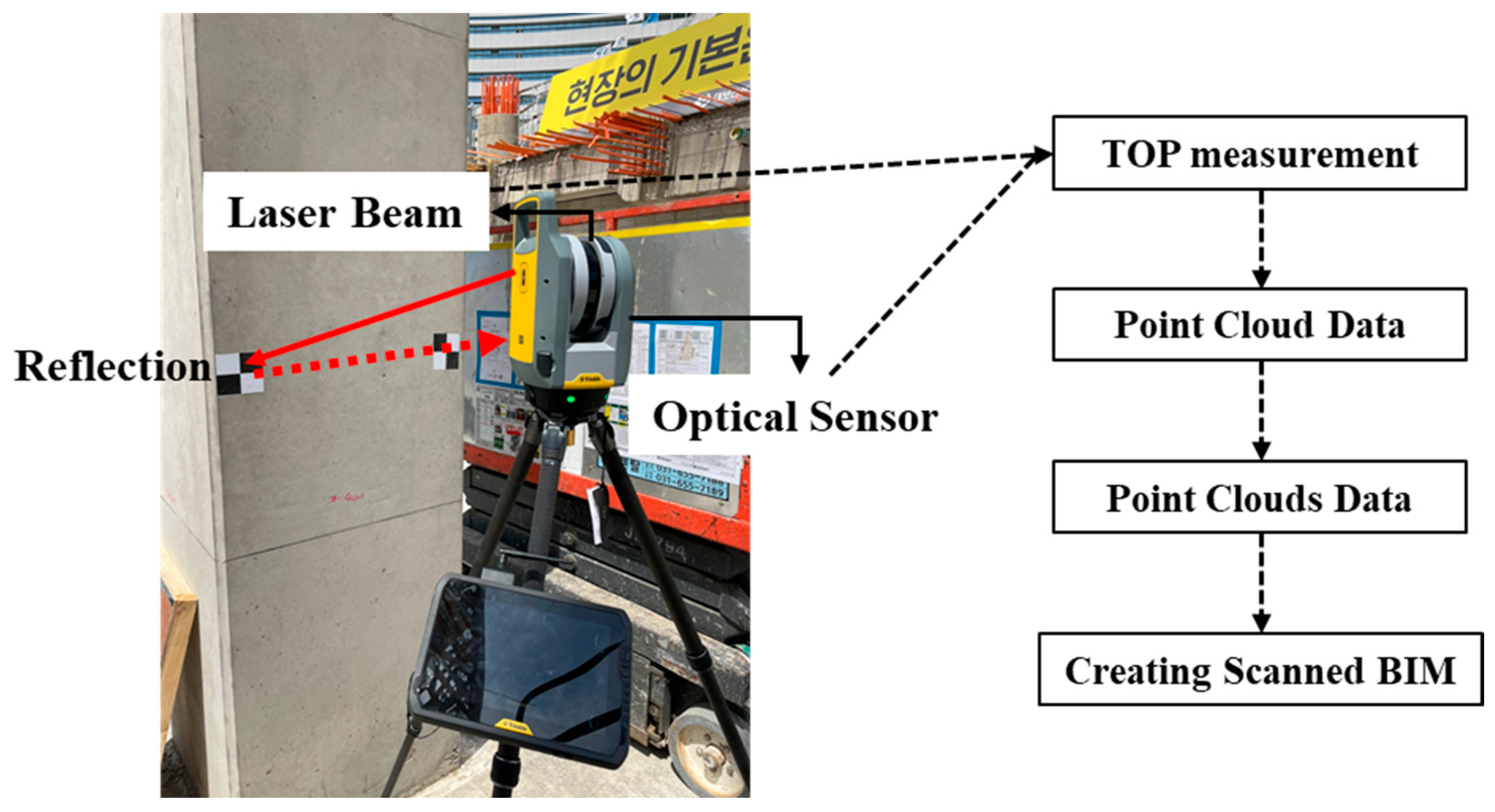
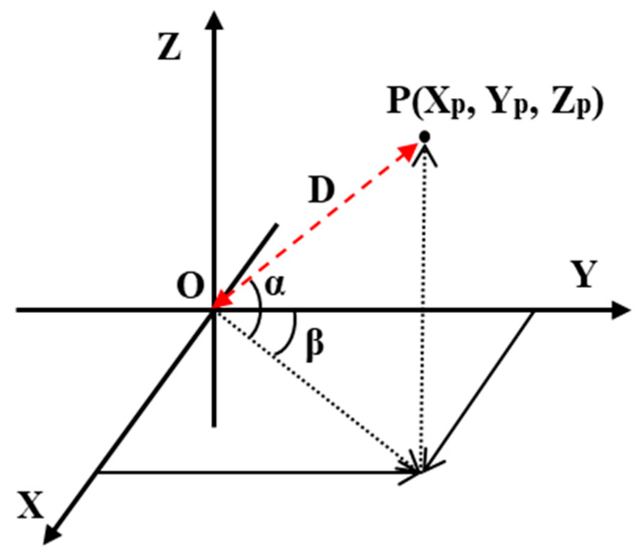
2.1. 3D Laser Scanning Technology

In particular, the rapid increase in the application of building information modeling (BIM) in recent years has suggested ways to apply various reality capture technologies to the construction field. These applications range from monitoring and managing construction projects to preparing as-built/as-is documents, and more [4]. The 3D laser scanner, which is a ground-based 3D reality capture technology, is the technology used to create detailed and accurate 3D building models. The 3D laser scanner can scan from multiple directions inside and outside the target building by adjusting the laser beam and record target points’ information including the X, Y, and Z co-ordinates, as well as information such as color, lighting, and so on [2], and utilizes time-of-flight or phase-based distance measurement principles to generate dense 3D point clouds of its surrounding [4], as shown in Figure 1.
As shown in Figure 2, 3D laser scanning uses a spherical co-ordinate system built inside the laser scanner along with the laser distance measurement method to achieve the measurement goal. Typically, the laser ranging beam has two mutually perpendicular axes around which it rotates and measures. The intersection of the rotation axes is the origin of the internal co-ordinate system, the horizontal rotation axis of the ground is the Y-axis, the X-axis is perpendicular to the Y-axis in the horizontal plane, and the Z-axis is perpendicular to the horizontal scanning plane, forming a right angle as shown in Figure 2. Considering an individual spatial point P, the distance between point P and the built-in co-ordinate origin O could be captured easily. The built-in laser scanner co-ordinate system is based on this; the absolute position of point P in the geodetic co-ordinate system that is expressed by (Xp, Yp, Zp) can be calculated by the co-ordinate transformation.
The 3D laser scanners are divided into three categories depending on the operating platform: the terrestrial laser scanner (TLS), mobile laser scanner (MLS), and airborne laser scanner (ALS) [3]. Among the three laser scanners, TLS is an efficient and reliable method for collecting point clouds which have a range of applications in the architecture, engineering, and construction (AEC) domain [4]. MLS can greatly improve the scanning efficiency and secure more data coverage, but the disadvantage of MLS is that it has a lower precision than TLS [3]. Due to complex indoor environmental problems, ALS is generally not used for data collection within buildings, but rather is utilized for large-scale data collection [46].
Therefore, Aryan et al. [5], in their study, suggest that the single-point accuracy of TLS is at the mm level and below, and the technology can measure millions of points in a matter of minutes. Moreover, TLS is suitable for the many fields of application, which include as-built/as-is documentation, construction activity monitoring dimensional quality control, asset monitoring, RE, cultural heritage recording, and urban planning, in the architectural, engineering, construction, and facilities management (AEC/FM) sector.

2.2. RE Using 3D Laser Scanner in Construction

Geng and Bidada [60] defined that RE is a systematic process that extracts design information from an existing product. Moreover, Bradley and Currie [61], in their study, presented that RE technology creates digital models using data collected from existing objects. Their interesting application areas of RE include the fields of computer arts, medical, dentistry, design/product development, manufacturing/product validation, and cultural heritage.
To obtain design information, accurate geometric data collection, also known as digitization, is always considered the starting point for any RE process [60]. Geng and Bidada [60] divided RE technologies into three types: the contact method, non-contact method, and hybrid method. Contact methods were subdivided into manual measurement, the co-ordinate measuring machine, and the numerical control-based machine; non-contact methods were subdivided into active and passive; and hybrid methods were subdivided into contact integrated with non-contact, and non-contact integrated with non-contact. As mentioned earlier, 3D laser scanners are an efficient and reliable method for collecting point clouds which have a range of applications in the AEC domain and, compared to traditional measurement technologies, 3D laser scanners are instruments with the advantages of having a high speed, large sampling capacity, much more information, high automation, no need for contact, and relatively high accuracy. Therefore, the 3D laser scanner can be said to be the most suitable instrument for RE technology.
Works of research have been conducted on RE using 3D laser scanning technology in the construction industry by applying it to quality control [62], structural diagnosis and evaluation [47,48,49], and pipes in plant construction [50], Even though plant construction projects must deal with complex 3D piping information, Korean construction companies rely on 2D CAD drawings for construction and quality control, which often causes serious problems such as construction delays and reduced productivity. Therefore, Lee et al. [51] proposed an RE algorithm that can measure the precision of pipes by comparing 3D shape information obtained from the 3D laser scanner and the 3D CAD model. Helle and Lemu [62] surveyed the literature to map the possibilities and challenges associated with methodologies and technologies using 3D scanning for RE and production control. Their case study on RE using a portable 3D laser scanner is performed, to be compare with the results from the existing literature. The case study results in that using 3D scanning for RE purposes have been shown to be best suited for components with complex geometries, such as free-form surfaces that are difficult to measure manually. Jang et al.‘s study [49,50] introduced an evaluation system utilizing RE using a 3D laser scanner. The advantage of the proposed system was that it allows the rapid and extensive inspection of structures for defects. Moreover, the proposed technology could secure data objectivity for emergency inspection technology compared to existing technologies. In a study by Lee et al. [51], a method to derive accurate building condition grading results was proposed because the evaluation results differ depending on the inspector’s judgment, have low objectivity, and lack reliability. Building defect data were collected using a reverse-engineered 3D model, and then compared with actual evaluation results to verify the accuracy of the results. The results showed a time savings of 50% over the same area with an approximately 90% accuracy. As mentioned earlier, the RE research using 3D laser scanning technology performed so far includes quality control, structural diagnosis and evaluation, pipe application in plant construction, the measurement of parts with complex shapes, structural defect inspection, a method to derive accurate building condition grading results, etc. There is no research on fundamental issues such as whether the building can continue to be constructed or whether it is legally unsatisfactory and must be demolished and rebuilt. In the future, RE using 3D laser scanning will be able to realize sustainable buildings in the construction industry by reducing costs, manpower, waste, and material losses by using building designs suited to site conditions, precise construction fitted to the building design, and building maintenance.

2.3. Application of 3D Laser Scanner to Setting out a Building

Setting out a building is the first step in constructing any building. This complex task has been carried out using specialized and expensive surveying instruments to minimize deviations in the construction area from the information provided in the design plans [63]. But, according to a questionnaire survey, which has been mentioned previously, conducted on construction field engineers and construction managers in South Korea, 82.5% of respondents responded that an architectural field engineer or a surveyor of a professional surveying company should check the accuracy of the building layout. Although the range of instruments currently available to the engineer or surveyor is very wide, the traditional surveying instruments such as the theodolite and level and steel tape would not be completely removed from the construction sites due to technical and cost considerations.
Figure 3 shows the RE procedure of checking the setting out of the building using a 3D laser scanner proposed in this study and making decisions by comparing the scanned 3D model with the building layout plan or BIM model and the flow of various data. The processes of checking the setting out of a building using 3D laser scanning is explained in detail as follows: First, the owner or client stores the data about the building created by the architect and surveyor in a database. Second, the operator prepares to perform 3D laser scanning. A plan should then be established, including selecting a 3D laser scanner suitable for the construction site environment and building characteristics and selecting an appropriate position for scanning. At this time, various data, such as the design drawings and topographic surveying drawings to be compared with the scanning results and control surveys and benchmark locations for scanning, should be checked. Third, the building data in the form of point cloud data (PCD) are acquired through scanning, and PCD for each 3D laser scanner position are combined to create a complete 3D model. When a complete 3D model is completed, if the building drawing is in the form of a 2D drawing in the database, the 2D drawing is extracted from the 3D model and compared, and, if it is in the form of a BIM model, the result is derived by comparing it with the 3D model. Fourth, if the deviation tolerance is within the permitted range, we proceed with construction as is, and, if corrections in the construction site are needed because the deviation exceed the permitted range, it is communicated to the construction site for correction. However, if construction is in progress, the building under construction is demolished and restarted from initial surveying stage, or, if RE is legally possible, the comparison results are delivered to the owner or client so that RE can be performed.

3. Field Application

3.1. A Case Description

Checking the setting out of a building on the site is ideally carried out at the beginning of construction, but, in this case, it was carried out after the foundation construction of the building was completed. Therefore, it was easy to check whether the setting out of the case building was different from the building layout drawing, because 3D laser scanning made it possible to see the building under construction. When checking whether the setting out of the case building was accurate, the 3D laser scanning results were compared with the topographic surveying drawing of the site and the case building layout plan. If the deviation exceeded the permitted range, the building foundation constructed will be demolished or RE will be executed to reflect the current location of the case building. At this time, it must be confirmed that the building layout plan that has been changed has no legal violations. The building of this case study is shown in Table 1.
In this case study, 3D laser scanning work was performed using Trimble’s TLS instrument, X7, and the specifications of the 3D laser scanner used are shown in Table 2. In addition, in consideration of the compatibility between the collected data, the software used was Trimble’s Realworks (version is 12.2) [64], which is provided by Trimble as the 3D laser scanner used in this study. Since the design drawings of the case building were drawn using Autodesk’s AUTOCAD, the 3D laser scanning results were extracted into 2D drawings and compared with the reference 2D drawings.

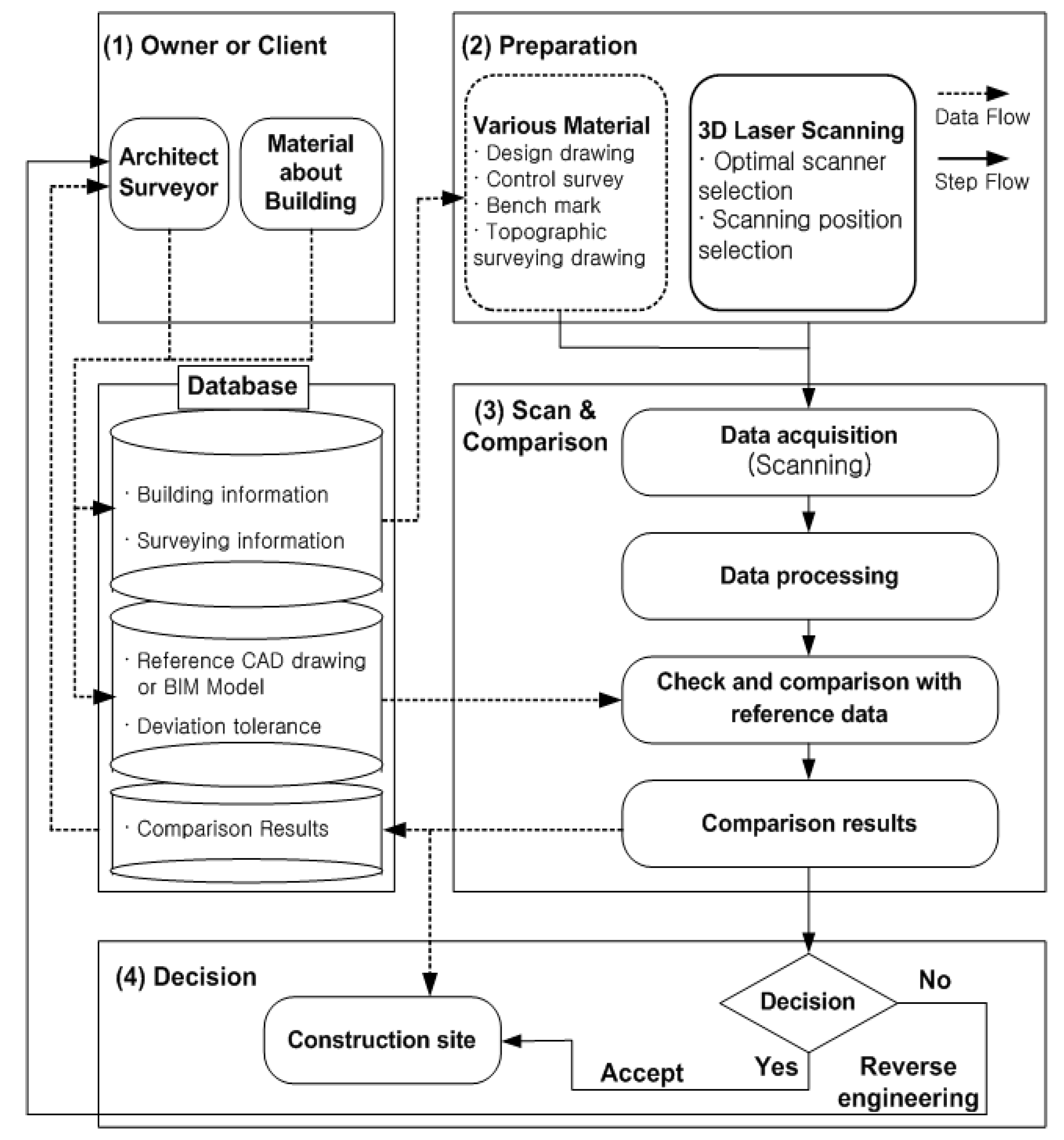
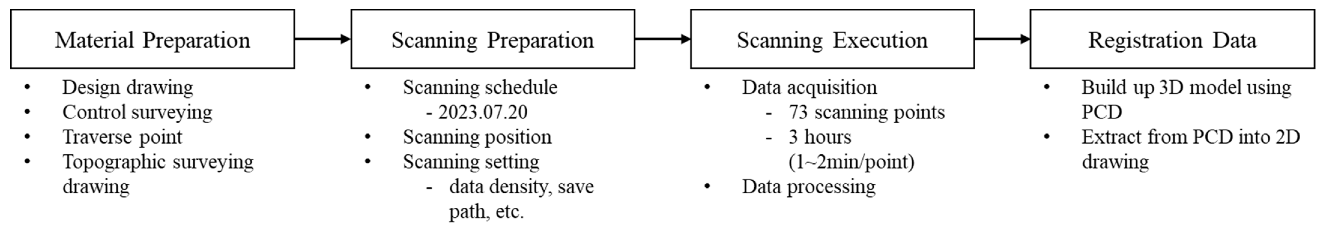
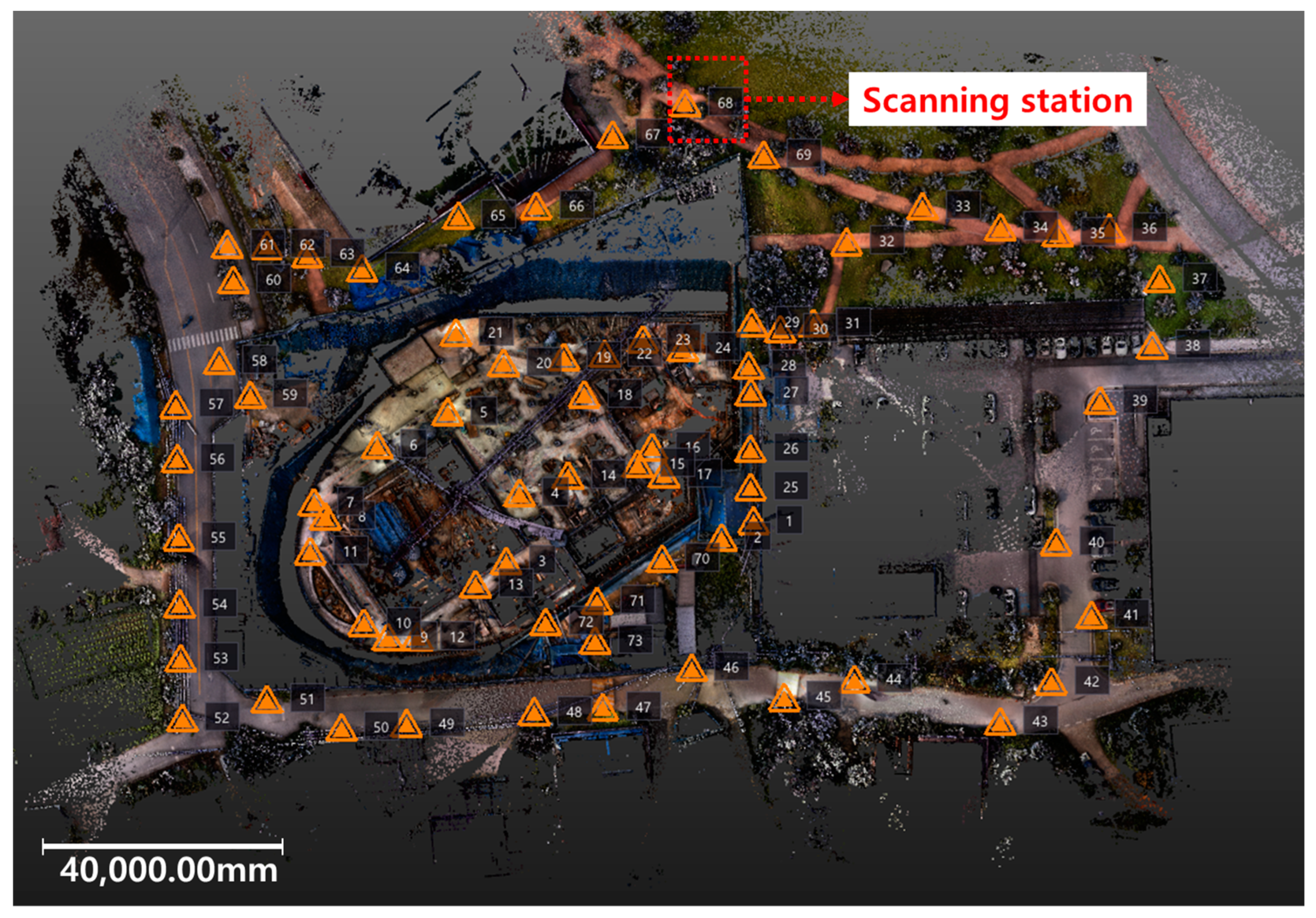
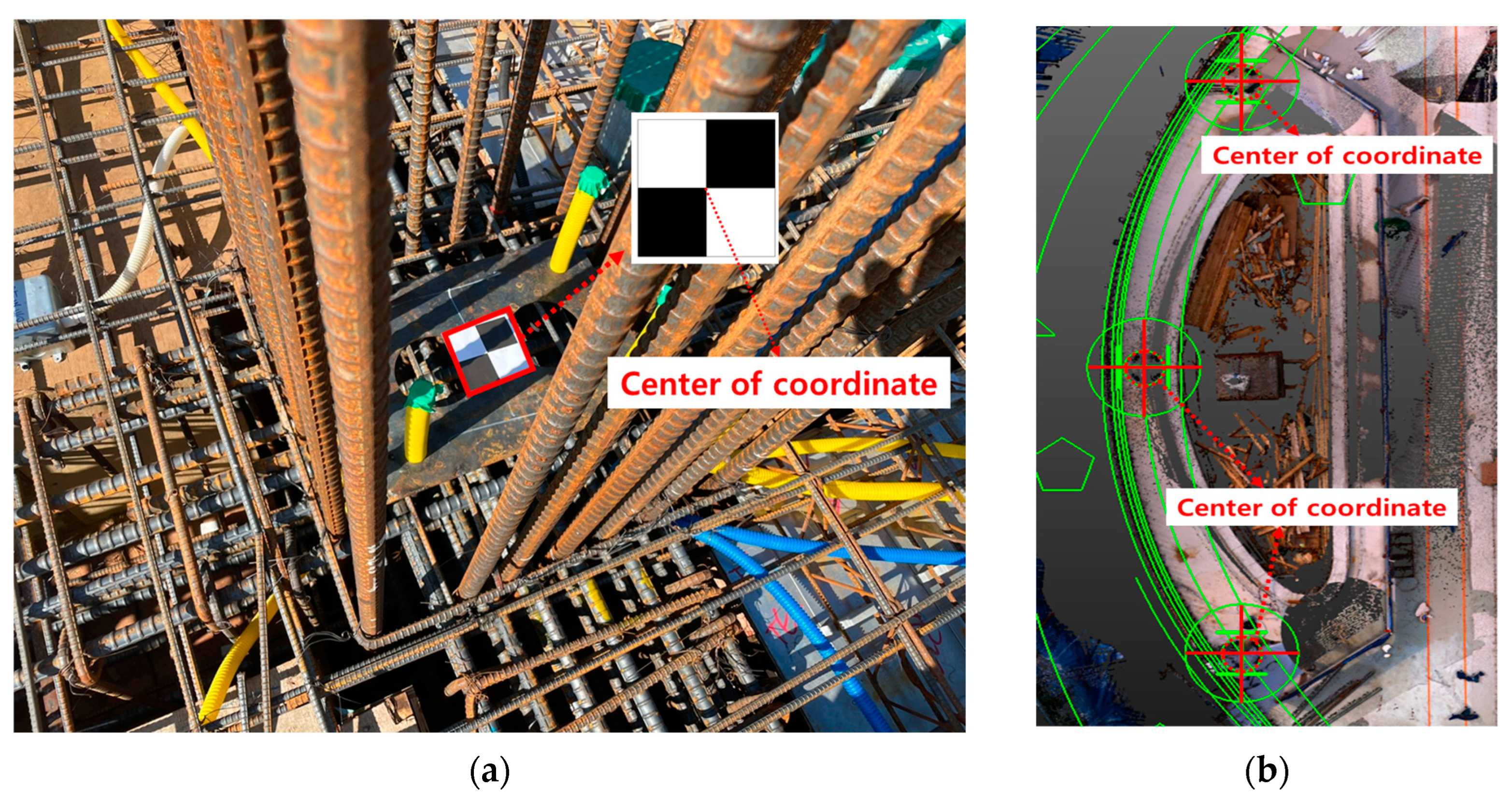
3.2. Scanning Process of Setting out the Case Building

To compare the building layout plan and the setting out of the case building under construction, the 3D laser scanning process was as shown in Figure 4, and the position of the scanner instrument scanned was as shown in Figure 5. In this study, a total of 73 scanning operations were conducted on construction sites using a 3D laser scanner to build 3D models. The time required for the 73 scanning station points was approximately 3 h, with each station taking about 1–2 min for the measurement. Additionally, the measurement range of the 3D laser scanning equipment was from 0.6 m to 80 m. When the minimum measurement range is 0.6 m, the lower shooting range of the equipment is limited to 270°. Therefore, considering the measurement range of the equipment, as well as factors such as columns, walls, and obstacles to measurement, the scanning operations were repeated at 73 scanning points around the construction site using the same process at multiple locations. Although the scanning time of 73 points is lengthy, it increases the overlap between multiple point cloud datasets, aiding in the alignment of the generated 3D model, enhancing accuracy, and reducing scanning shadows. Accuracy, in this context, refers to the combination of point cloud datasets generated for each scanning station point to create one complete point cloud dataset, i.e., one complete 3D model, with fewer errors. Although capturing multiple data from the same location for 3D model construction can affect the number of points constituting the 3D model, it does not contribute to improving the accuracy. This is because the accuracy of the 3D model is determined by the density of laser points transmitted and received in the same area, rather than the number of operations. Furthermore, unnecessary data collection from the same location was not performed within the designated operation time for 3D laser scanning. Therefore, in this study, 73 operations were performed at various locations around the construction site, collecting 5 million points per operation as the precision of laser points transmitted and received by the 3D laser scanner. This process is explained in detail as follows: First, various materials about the case building are collected, that is, design drawings, control surveying, bench marks, and topographic surveying drawings. Second, we make a preparation plan for the 3D laser scanning operation; that is, we make a preparation plan by considering the construction site schedule, including the position of the scanner for scanning and the scanning schedule and so on. This is because, at a construction site, as various types of work are executed in a complex manner, many materials, temporary works, and equipment used in the work are distributed on the site, and these objects create shadow areas that obscure data during the 3D laser scanning operation and this area may deteriorate the data quality. In addition, we set the scanner according to the time required to collect the data and the purpose of the data usage. If there is a lot of data collection time or there is a need to minimize errors such as flatness and verticality, we set the data collection density of the 3D laser scanner to be higher, and vice versa for if there is little data collection time, or if there is a need to approximate the building’s layout on the site or the identification of building members, etc. When used to analyze information about the shape, the data are acquired quickly by lowering the data collection density of the 3D laser scanner.
Third, the data are acquired through 3D laser scanning using the planned position and path and the scanner’s set values. During the data acquisition process, the co-ordinate points for analysis can be set as needed. The reason for this is that, if the position point cannot be set, such as the loss of the traverse point on site as shown in Figure 6b, secondary position points are marked at the center or corner of the column, the wall of the existing surrounding building, and secondary position points that can be confirmed in the drawing, as shown in Figure 6a. It can be used as a reference point in the comparing process. Fourth, registration is performed to produce point cloud data (PCD), one 3D model, of point clouds collected from multiple scanning positions.

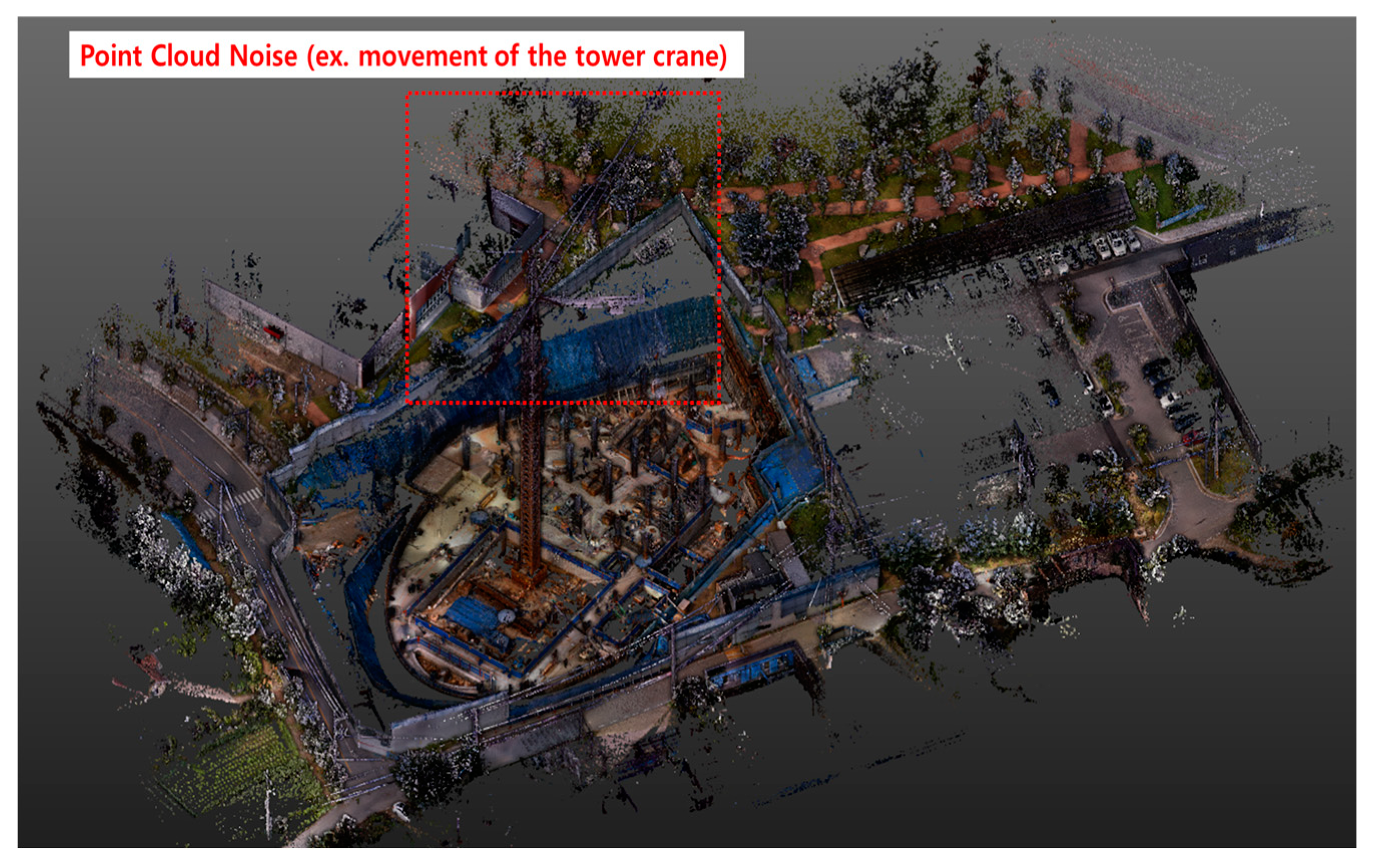
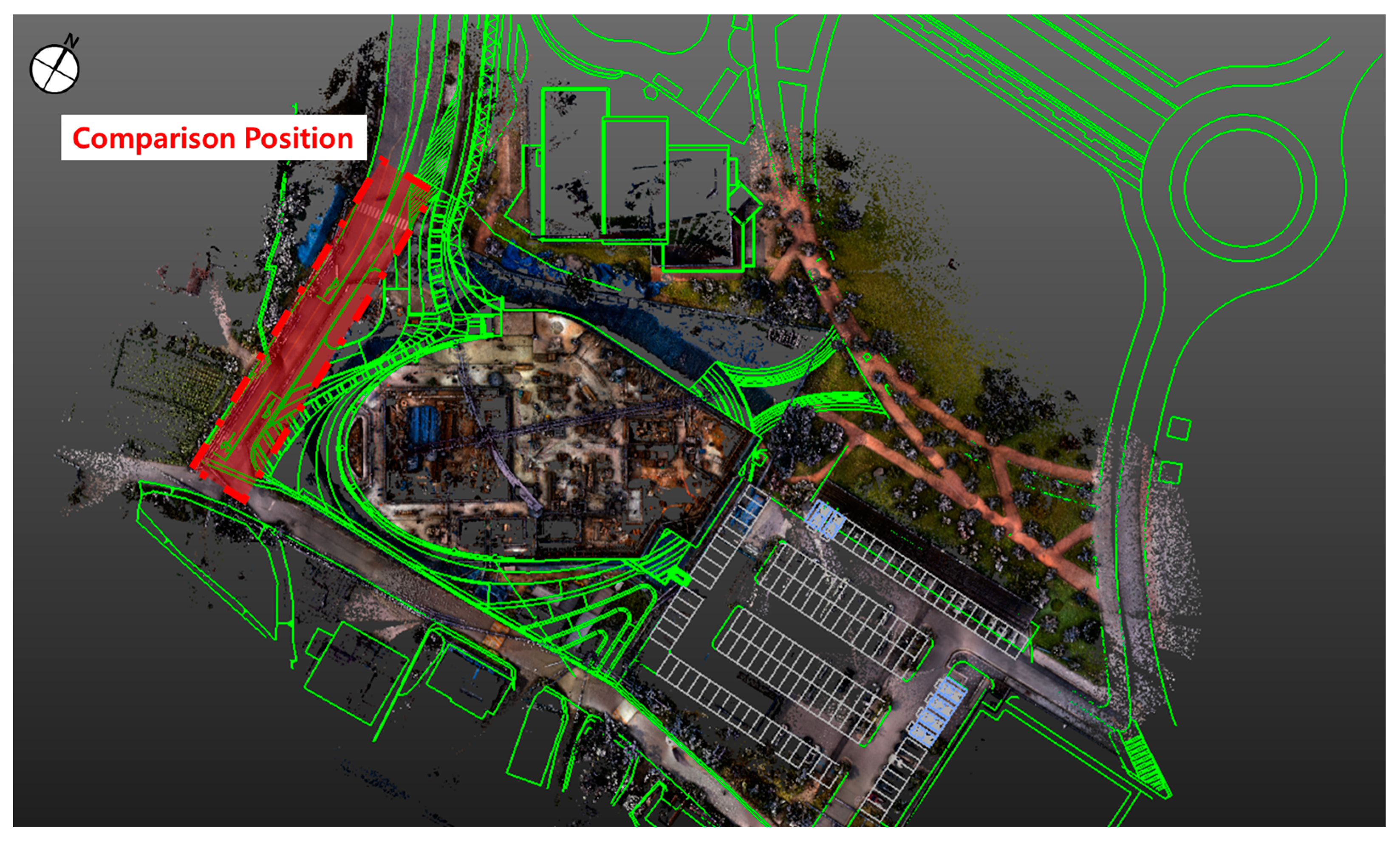
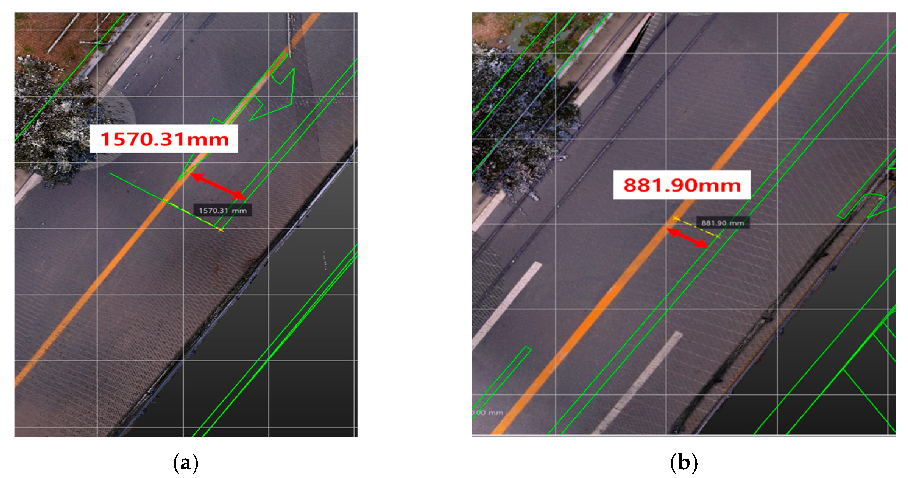
3.3. Results of 3D Laser Scanning

In this study, the results of applying the 3D laser scanning technology to a construction site are shown in Figure 6. The point cloud was collected from a total of 73 scanning positions, and the collected data were registered using Auto-Registration provided by Trimble’s Realworks. Figure 7 showed the noise generated in PCD for a moving object (tower crane) during 3D laser scanning. Although efforts have been made to improve the quality of the result of 3D laser scanning (Figure 7), it revealed that clear identification is difficult to achieve due to limitations in the software’s ability to accurately identify objects in their true colors.
As a result of the combination of each PCD, the combining error between the point clouds of each position was found to be 3.42 mm. It was confirmed that this combining error was similar to the instrument error of 3.5 mm. In addition, the reason for the combining error may be that the movement of tower cranes, workers, vehicles, etc. in the data collected during construction occurred while operating the 3D laser scanner, causing errors in the points used for registration.
In order to utilize the PCD created using the 3D laser scanning technology in this study, it is essential to set reference co-ordinates between the drawing and the PCD. However, the traverse point, which is mainly used for comparison, was lost during construction, so a reference point was created at the center of the column, as shown in Figure 6a, and a comparison between the drawing and the PCD was performed. Accordingly, when a comparison was conducted with the center of column inside the building, it was confirmed whether the location of the building or roads that had already existed matched the locations on the layout plan.
As shown in Figure 8, the topographic surveying drawing was compared with the PCD, and the layout plan was compared with the PCD as shown in Figure 9. As a result of the comparison, it was confirmed that the topographic surveying drawing was consistent with the PCD collected from the site, but the layout plan showed that the road on the east side of the site and the existing building on the north side of the site was different from the drawing. As a result of comparing the layout plan and the PCD, it was found that there was a minimum difference of 881.90 mm and a maximum of 1570.31 mm based on the center of the road, as shown in Figure 10. This shows that, when comparing the center lines of the road, the buildings under construction in the east moved to the west in the layout plan. As a result, the topographic surveying was performed normally and the topographic surveying drawing was created, but it is believed that the building layout plan was created without comparing the building layout plan and the topographic surveying drawing, and the setting out of the building for construction work is wrong because the building layout plan was created incorrectly.

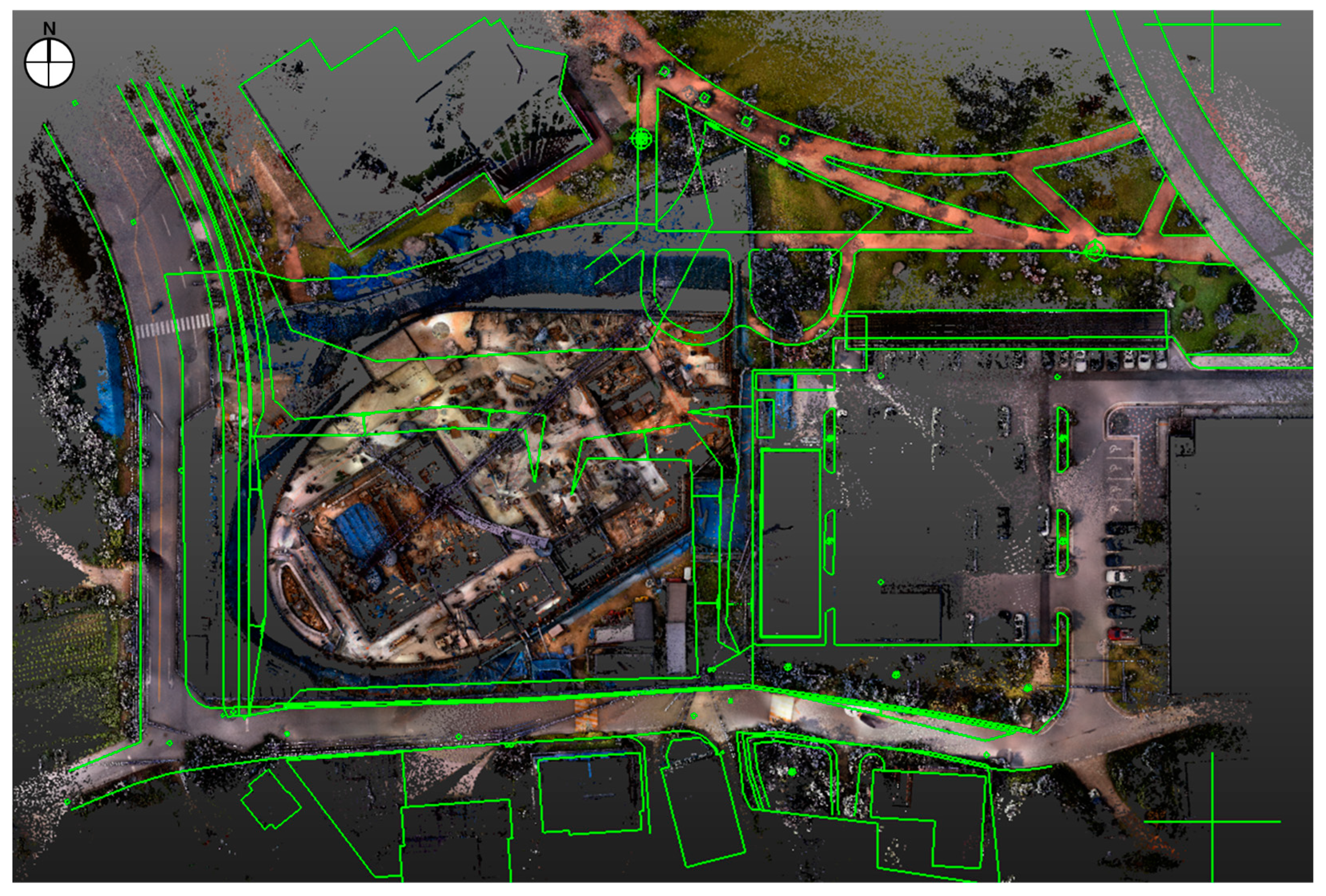
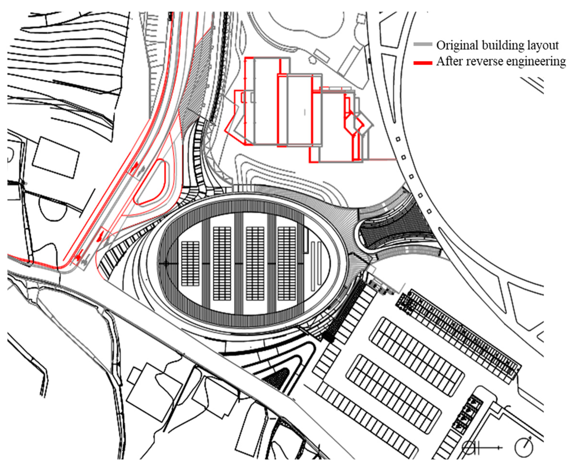
3.4. RE of Building Layout Design

It was confirmed that the setting out of the case building did not match the location of the building layout plan by checking the error through overlapping the building layout plan drawing and the 3D model of the building and site obtained through 3D laser scanning, with the result that it was moved an average of 1226 mm to the west of the site. Therefore, in a situation where the building had to be demolished and rebuilt, it was inevitable that demolition costs, waste disposal costs, and construction schedule delays would occur. Therefore, whether the location of building currently under construction was outside the site boundary or violated the building act was checked firstly. Fortunately, it was not the worst-case scenario as it did not deviate from the boundary line of the site or violate the building act, and it was judged that continuing construction would be sustainable construction. The reason is that preventing construction delays, increases in construction costs, and waste generation can all be considered sustainable construction. Therefore, the plan to modify the building layout plan according to the results of checking the setting out of the building using a 3D laser scanner was presented to the client, and RE was performed to modify the building layout plan. The RE results are presented in Figure 11. As shown in Figure 11, the road location and the location of the existing building shown on the building layout plan was also modified. Furthermore, regarding the costs, detailed comparisons were not feasible due to the absence of data based on cost estimation. However, considering factors such as the number of instruments used and the involvement of professionals, it is estimated that the costs incurred would be similar to or lower than those of traditional methods.

4. Discussion

In this study, the accuracy of the setting out of the building on a site was confirmed using 3D laser scanning, and, if it exceeded the permitted range, the process of solving it through RE was studied. The analysis of the case presented in this study revealed that errors occurred not during the surveying phase but during the design phase in the initial construction of the building. This was confirmed by comparing the PCD acquired from the construction site with the surveying drawing, where errors were not found in the topographic surveying drawing but were found when compared to the building layout plan. As a result, by modifying the layout drawings to achieve an alignment between the design and construction, this study facilitated the co-ordination between the design and construction phases and demonstrated the potential of the 3D laser scanning technology proposed herein in addressing issues arising in construction projects. Therefore, utilizing 3D laser scanning technology from the early stage of construction, such as building layout verification, can contribute to the realization of sustainable buildings. And it was possible to confirm that sustainable construction management and a sustainable environment could be achieved by preventing construction delays, increased construction costs, and waste generation.
To date, many studies have already shown that 3D laser scanning technology can be used in a variety of ways in the construction industry. In addition, it could be applied in a variety of ways in the field of RE, but, in this study, it was confirmed that it is also useful for setting out buildings on a site in the early stages of building construction or checking whether the setting out of a building matches the building layout plan. In addition, it is not limited to the setting out of the building, but can be applied in a variety of ways, such as checking the base lines in the building construction, checking the location of members such as columns or walls that have completed construction, or checking the location of pipes.
The most important thing here is that the existing surveying method or GPS confirms a specific point, and the 3D laser scanning method allows for a comparison with the CAD drawing in a three-dimensional method at once. In addition, while existing surveying methods and GPS methods require expert knowledge of surveying, anyone can use the 3D laser scanner as long as they know how to operate the scanner and the related software. Especially, Gimeno et al. [63] conducted a study on applying augmented reality techniques (ARTs) to the setting-out management and stated the efficient quality/cost trade-off for setting-out purposes in actual construction sites. It can be said that the setting-out management by applying ART has limitations when an actual building is constructed. In other words, it is judged to be just appropriate for marking the building layout on site.
It is believed that various surveying tasks performed after control surveying can be performed using a 3D laser scanner. It is believed that these tasks can be performed without error even if architectural engineers or construction managers are not professional surveyors, if they know how to operate a 3D laser scanner and the related software, so errors in the field can be minimized. However, the price of 3D laser scanners and the related software is quite high; it is quite expensive to own and operate the instrument at each building construction site, and it takes a lot of time to learn how to operate them, so there is a limit to their spread. Consequently, it would be necessary to compare the cost of applying a 3D scanner to the building construction project and the costs that may arise due to errors in the setting out of the building, etc.; here, the costs that may arise due to errors in the setting out of the building are quite difficult to measure. This is because the costs range from re-establishing the main base line of the building, to demolishing the constructed building in the worst case, and then rebuilding the building. However, anyone can see that, if the problem is resolved early, by using a 3D laser scanner to confirm initially, and then resetting out the building or implementing RE in building layout plan drawing, the cost is extremely low, and they can determine and select which option could lead to a sustainable building and sustainable construction management.

5. Conclusions and Future Research

In this study, a case study was conducted to use a 3D laser scanner to check whether the setting out of a building under construction matched with the building layout plan, and to resolve the deviation of the setting out of the building through RE when the deviation exceeded the permitted range. The 3D scanning technology is very effective in checking the setting out of the building because, if there is a BIM model of the building, it can be checked by comparing the BIM model with a 3D point cloud model, and, if there is only a 2D drawing of the building, it can be checked by comparing the 2D drawing with a 2D drawing which is be extracted from the point cloud data.
Although the 3D laser scanner and the related software have the disadvantage of being quite expensive and requiring learning to operate them, architectural field engineers or construction managers can handle them even if they are not professional surveyors, and they can be useful in various fields such as progress measurement, quality control, and so on, until the building construction project is completed. Ultimately, construction costs, construction time, manpower, and waste can be reduced by reducing construction management errors using 3D laser scanning technology, which will play a major role in sustainable construction management.
In future research, the scope of the application of 3D laser scanners will be able to be expanded even further if research is conducted not only to confirm the setting out of a building but also to check the location or size of each member of the building and use it to create as-built drawings.

Author Contributions

H.K.: conceptualization, methodology, and writing—original draft preparation; J.-Y.K.: writing, data acquisition, and visualization; Y.S.: project administration, and writing—review and editing. All authors have read and agreed to the published version of the manuscript.

Funding

This work was supported by the National Research Foundation of Korea(NRF) grant funded by the Korea government(MSIT) (No. 2022R1A4A5028239).

Institutional Review Board Statement

Not applicable.

Informed Consent Statement

Not applicable.

Data Availability Statement

The data presented in this study are available upon request from the corresponding author. The data are not publicly available due to restrictions on the right to privacy.

Conflicts of Interest

The authors declare no conflicts of interest.

References

  1. Andrich, W.; Daniotti, B.; Pavan, A.; Mirarchi, C. Check and Validation of Building Information Models in Detailed Design Phase: A Check Flow to Pave the Way for BIM Based Renovation and Construction Processes. Buildings 2022, 12, 154. [Google Scholar] [CrossRef]
  2. Wang, J.; Yi, T.; Liang, X.; Ueda, T. Application of 3D Laser Scanning Technology Using Laser Radar System to Error Analysis in the Curtain Wall Construction. Remote Sens. 2023, 15, 64. [Google Scholar] [CrossRef]
  3. Akinci, B.; Boukamp, F.; Gordon, C.; Huber, D.; Lyons, C.; Park, K. A formalism for utilization of sensor systems and integrated project models for active construction quality control. Autom. Constr. 2006, 15, 124–138. [Google Scholar] [CrossRef]
  4. Bassier, M.; Yousefzadeh, M.; Van Genechten, B. Evaluation of data acquisition techniques and workflows for scan to BIM. In Proceedings of the Geo Business Conference, London, UK, 27–28 May 2015; Available online: https://lirias.kuleuven.be/1675091?limo=0 (accessed on 11 April 2024).
  5. Aryan, A.; Bosché, F.; Tang, P. Planning for terrestrial laser scanning in construction: A review. Autom. Constr. 2021, 125, 103551. [Google Scholar] [CrossRef]
  6. Wu, C.; Yuan, Y.; Tang, Y.; Tian, B. Application of Terrestrial Laser Scanning (TLS) in the Architecture, Engineering and Construction (AEC) Industry. Sensors 2022, 22, 265. [Google Scholar] [CrossRef]
  7. Haleem, A.; Javaid, M.; Singh, R.P.; Rab, S.; Suman, R.; Kumar, L.; Khan, I.H. Exploring the potential of 3D scanning in Industry 4.0: An overview. Int. J. Cogn. Comput. Eng. 2022, 3, 161–171. [Google Scholar] [CrossRef]
  8. Bhatti, A.Q.; Wahab, A.; Sindi, W. An overview of 3D laser scanning techniques and application on digitisation of historical structures. Innov. Infrastruct. Solut. 2021, 6, 1–9. [Google Scholar] [CrossRef]
  9. Xiong, X.; Adan, A.; Akinci, B.; Huber, D. Automatic creation of semantically rich 3D building models from laser scanner data. Autom. Constr. 2013, 31, 325–337. [Google Scholar] [CrossRef]
  10. Lovell, L.J.; Davies, R.J.; Hunt, D.V.L. The Application of Historic Building Information Modelling (HBIM) to Cultural Heritage: A Review. Heritage 2023, 6, 6691–6717. [Google Scholar] [CrossRef]
  11. León-Robles, C.A.; Reinoso-Gordo, J.F.; González-Quiñones, J.J. Heritage Building Information Modeling (H-BIM) Applied to A Stone Bridge. ISPRS Int. J. Geo-Inf. 2019, 8, 121. [Google Scholar] [CrossRef]
  12. Biagini, C.; Capone, P.; Donato, V.; Facchini, N. Towards the bim implementation for historical building restoration sites. Autom. Constr. 2016, 71, 74–86. [Google Scholar] [CrossRef]
  13. Garavaglia, E.; Anzani, A.; Maroldi, F.; Vanerio, F. Non-invasive identification of vulnerability elements in existing buildings and their visualization in the bim model for better project management: The case study of cuccagna farmhouse. Appl. Sci. 2020, 10, 2119. [Google Scholar] [CrossRef]
  14. Kim, S.; Kim, S.; Lee, D.-E. 3D point cloud and bim-based reconstruction for evaluation of project by as-planned and as-built. Remote Sens. 2020, 12, 1457. [Google Scholar] [CrossRef]
  15. Ma, L.; Sacks, R.; Kattel, U.; Bloch, T. 3D object classification using geometric features and pairwise relationships. Comput.-Aided Civ. Infrastruct. Eng. 2018, 33, 152–164. [Google Scholar] [CrossRef]
  16. Mustafa, M.H.; Ali, M.; Hashim, K.S.H.Y.; Suhaimi, M.S.M. Recreating historical malay architecture with bim process. Int. J. Built Environ. Sustain. 2020, 7, 79–89. [Google Scholar] [CrossRef]
  17. Shanbari, H.A.; Blinn, N.M.; Issa, R.R. Laser scanning technology and bim in construction management education. J. Inf. Technol. Constr. 2016, 21, 204–217. [Google Scholar]
  18. Xu, Y.; Shen, X.; Lim, S. Cordet: Corner-aware 3D object detection networks for automated scan-to-bim. J. Comput. Civ. Eng. 2021, 35, 04021002. [Google Scholar] [CrossRef]
  19. Zhao, L.; Zhang, H.; Wang, Q.; Wang, H. Digital-Twin-Based evaluation of nearly zero-energy building for existing buildings based on scan-to-bim. Adv. Civ. Eng. 2021, 2021, 6638897. [Google Scholar] [CrossRef]
  20. Wang, Q.; Sohn, H.; Cheng, J.C.P. Automatic as-built BIM creation of precast concrete bridge deck panels using laser scan data. J. Comput. Civ. Eng. 2018, 32, 04018011. [Google Scholar] [CrossRef]
  21. Bosche, F. Automated recognition of 3D cad model objects in laser scans and calculation of as-built dimensions for dimensional compliance control in construction. Adv. Eng. Inform. 2010, 24, 107–118. [Google Scholar] [CrossRef]
  22. Braun, A.; Tuttas, S.; Borrmann, A.; Stilla, U. Improving progress monitoring by fusing point clouds, semantic data and computer vision. Autom. Constr. 2020, 116, 103210. [Google Scholar] [CrossRef]
  23. Maalek, R.; Lichti, D.D.; Ruwanpura, J.Y. Automatic Recognition of Common Structural Elements from Point Clouds for Automated Progress Monitoring and Dimensional Quality Control in Reinforced Concrete Construction. Remote Sens. 2019, 11, 1102. [Google Scholar] [CrossRef]
  24. Chang, K.T.; Wang, E.H. Developing procedures for post-earthquake structural evaluation by laser scanning techniques. Insight-Non-Destr. Test. Cond. Monit. 2012, 54, 562–567. [Google Scholar] [CrossRef]
  25. Jaafar, H.A.; Meng, X.; Sowter, A.; Bryan, P. New approach for monitoring historic and heritage buildings: Using terrestrial laser scanning and generalised procrustes analysis. Struct. Control Health Monit. 2017, 24, e1987. [Google Scholar] [CrossRef]
  26. Mader, D.; Blaskow, R.; Westfeld, P.; Weller, C. Potential of UAV-based laser scanner and multispectral camera data in building inspection. Int. Arch. Photogramm. Remote Sens. Spat. Inf. Sci. 2016, 41, 1135–1142. [Google Scholar] [CrossRef]
  27. Skrzypczak, I.; Oleniacz, G.; Leśniak, A.; Zima, K.; Mrówczyńska, M.; Kazak, J.K. Scan-to-BIM method in construction: Assessment of the 3D buildings model accuracy in terms inventory measurements. Build. Res. Inf. 2022, 50, 859–880. [Google Scholar] [CrossRef]
  28. Li, H.; Zhang, C.; Song, S.; Demirkesen, S.; Chang, R. Improving Tolerance Control on Modular Construction Project with 3D Laser Scanning and BIM: A Case Study of Removable Floodwall Project. Appl. Sci. 2020, 10, 8680. [Google Scholar] [CrossRef]
  29. Xu, Z.; Kang, R.; Lu, R. 3D reconstruction and measurement of surface defects in prefabricated elements using point clouds. J. Comput. Civ. Eng. 2020, 34, 04020033. [Google Scholar] [CrossRef]
  30. Kim, M.-K.; Cheng, J.C.P.; Sohn, H.; Chang, C.-C. A framework for dimensional and surface quality assessment of precast concrete elements using BIM and 3D laser scanning. Autom. Constr. 2015, 49, 225–238. [Google Scholar] [CrossRef]
  31. Kim, M.K.; Wang, Q.; Park, J.W.; Cheng, J.C.P.; Sohn, H.; Chang, C.C. Automated dimensional quality assurance of full-scale precast concrete elements using laser scanning and bim. Autom. Constr. 2016, 72, 102–114. [Google Scholar] [CrossRef]
  32. Arashpour, M.; Heidarpour, A.; Nezhad, A.; Hosseinifard, Z.; Chileshe, N.; Hosseini, R. Performance-based control of variability and tolerance in off-site manufacture and assembly: Optimization of penalty on poor production quality. Constr. Manag. Econ. 2020, 38, 502–514. [Google Scholar] [CrossRef]
  33. Hess, M.; Petrovic, V.; Yeager, M.; Kuester, F. Terrestrial laser scanning for the comprehensive structural health assessment of the baptistery di san giovanni in florence, italy: An integrative methodology for repeatable data acquisition, visualization and analysis. Struct. Infrastruct. Eng. 2018, 14, 247–263. [Google Scholar] [CrossRef]
  34. Sanchez-Rodriguez, A.; Riveiro, B.; Conde, B.; Soilan, M. Detection of structural faults in piers of masonry arch bridges through automated processing of laser scanning data. Struct. Control Health Monit. 2018, 25, e2126. [Google Scholar] [CrossRef]
  35. Riveiro, B.; Morer, P.; Arias, P.; de Arteaga, I. Terrestrial laser scanning and limit analysis of masonry arch bridges. Constr. Build. Mater. 2011, 25, 1726–1735. [Google Scholar] [CrossRef]
  36. Arias, P.; Riveiro, B.; Armesto, J.; Solla, M. Terrestrial laser scanning and non parametric methods in masonry arches inspection. In Proceedings of the ISPRS-Commission V Mid-Term Symposium: Close Range Image Measurement Technique, Newcastle upon Tyne, UK, 21–24 June 2010; pp. 39–44. [Google Scholar]
  37. Bassier, M.; Vergauwen, M. Topology Reconstruction of BIM Wall Objects from Point Cloud Data. Remote Sens. 2020, 12, 1800. [Google Scholar] [CrossRef]
  38. Park, C.-S.; Lee, D.-Y.; Kwon, O.-S.; Wang, X. A framework for proactive construction defect management using BIM, augmented reality and ontology-based data collection template. Autom. Constr. 2013, 33, 61–71. [Google Scholar] [CrossRef]
  39. Getuli, V.; Ventura, S.M.; Capone, P.; Ciribini, A.L.C. A BIM-based construction supply chain framework for monitoring progress and coordination of site activities. Procedia Eng. 2016, 164, 542–549. [Google Scholar] [CrossRef]
  40. Zhang, C.; Arditi, D. Automated progress control using laser scanning technology. Autom. Constr. 2013, 36, 108–116. [Google Scholar] [CrossRef]
  41. Khairadeen Ali, A.; Lee, O.J.; Lee, D.; Park, C. Remote Indoor Construction Progress Monitoring Using Extended Reality. Sustainability 2021, 13, 2290. [Google Scholar] [CrossRef]
  42. Turkan, Y.; Bosché, F.; Haas, C.T.; Haas, R. Automated progress tracking using 4D schedule and 3D sensing technologies. Autom. Constr. 2012, 22, 414–421. [Google Scholar] [CrossRef]
  43. Son, H.; Kim, C.; Cho, Y.K. Automated schedule updates using as-built data and a 4d building information model. J. Manag. Eng. 2017, 33, 04017012. [Google Scholar] [CrossRef]
  44. Wang, Y.; Chen, Q.; Zhu, Q.; Liu, L.; Li, C.; Zheng, D. A Survey of Mobile Laser Scanning Applications and Key Techniques over Urban Areas. Remote Sens. 2019, 11, 1540. [Google Scholar] [CrossRef]
  45. Wang, C.; Wen, C.; Dai, Y.; Yu, S.; Liu, M. Urban 3D modeling using mobile laser scanning: A review. Virtual Real. Intell. Hardw. 2020, 2, 175–212. [Google Scholar] [CrossRef]
  46. Chen, D.; Zhang, L.; Mathiopoulos, P.T.; Huang, X. A methodology for automated segmentation and reconstruction of urban 3-D buildings from ALS point clouds. IEEE J. Sel. Top. Appl. Earth Obs. Remote Sens. 2014, 7, 4199–4217. [Google Scholar] [CrossRef]
  47. Nguyen, T.A.; Nguyen, P.T.; Tien, S. Application of BIM and 3D Laser Scanning for Quantity Management in Construction Projects. Adv. Civ. Eng. 2020, 2020, 8839923. [Google Scholar] [CrossRef]
  48. Kim, S.; Lee, J.M.; Kim, S. Safety diagnosis process for deteriorated buildings using a 3D scan-based reverse engineering model. Smart Struct. Systems. Int. J. 2023, 31, 79–88. [Google Scholar]
  49. Jang, A.; Jeong, S.; Park, M.J.; Ju, Y.K. Structural evaluation by reverse engineering with 3D laser scanner. Proc. Civ. Eng. 2023, 6, 308–314. [Google Scholar] [CrossRef]
  50. Jang, A.; Ju, Y.K.; Park, M.J. Structural Stability Evaluation of Existing Buildings by Reverse Engineering with 3D Laser Scanner. Remote Sens. 2022, 14, 2325. [Google Scholar] [CrossRef]
  51. Lee, M.; Lee, S.; Kwon, S.; Chin, S. A study on scan data matching for reverse engineering of pipes in plant construction. KSCE J. Civ. Eng. 2017, 21, 2027–2036. [Google Scholar] [CrossRef]
  52. Ham, N.; Lee, S.-H. Empirical Study on Structural Safety Diagnosis of Large-Scale Civil Infrastructure Using Laser Scanning and BIM. Sustainability 2018, 10, 4024. [Google Scholar] [CrossRef]
  53. Banfi, F.; Barazzetti, L.; Previtali, M.; Roncoroni, F. Historic BIM: A new repository for structural health monitoring. Int. Arch. Photogramm. Remote Sens. Spat. Inf. Sci. 2017, 42, 269–274. [Google Scholar] [CrossRef]
  54. Rolin, R.; Antaluca, E.; Batoz, J.L.; Lamarque, F.; Lejeune, M. From point cloud data to structural analysis through a geometrical hBIM-oriented model. J. Comput. Cult. Herit. 2019, 12, 1–26. [Google Scholar] [CrossRef]
  55. Patil, G.P.; Chen, D.; Mayo, G.; Smithwick, J.; Barclay, N. Implementing BIM and finite element analysis in a structural integrity investigation of curtain walls. J. Facility Manag. Educ. Res. 2019, 3, 27–37. [Google Scholar] [CrossRef] [PubMed]
  56. Zeibak-Shini, R.; Sacks, R.; Ma, L.; Filin, S. Towards generation of as-damaged BIM models using laser-scanning and as-built BIM: First estimate of as-damaged locations of reinforced concrete frame members in masonry infill structures. Adv. Eng. Inform. 2016, 30, 312–326. [Google Scholar] [CrossRef]
  57. Dimitrov, A.; Golparvar-Fard, M. Segmentation of building point cloud models including detailed architectural/structural features and MEP systems. Autom. Constr. 2015, 51, 32–45. [Google Scholar] [CrossRef]
  58. Czerniawski, T.; Nahangi, M.; Haas, C.; Walbridge, S. Pipe spool recognition in cluttered point clouds using a curvature-based shape descriptor. Autom. Constr. 2016, 71, 346–358. [Google Scholar] [CrossRef]
  59. Muskett, J. Site Surveying, 2nd ed.; Wiley-Blackwell: New Jersey, NJ, USA, 1995; pp. 1–416. [Google Scholar]
  60. Walker, J.; Awange, J.L. Surveying for Civil and Mine Engineers; Theory, Workshops, and Practicals, 1st ed.; Springer International Publishing AG: Cham, Switzerland, 2018; pp. 55–79. [Google Scholar]
  61. Geng, Z.; Bidanda, B. Review of reverse engineering systems–current state of the art. Virtual Phys. Prototyp. 2017, 12, 161–172. [Google Scholar] [CrossRef]
  62. Bradley, C.; Currie, B. Advances in the Field of Reverse Engineering. Comput.-Aided Des. Appl. 2005, 2, 697–706. [Google Scholar] [CrossRef]
  63. Gimeno, J.; Riera, J.V.; Morillo, P.; Fernández, M. A New Approach to the Management of the Setting out in Construction based on Augmented Reality Techniques. Civil-Comp Proceedings 94. In Proceedings of the Seventh International Conference on Engineering Computational Technology 2010, Valencia, Spain, 14–17 September 2010; Topping, B.H.V., Adam, J.M., Pallarés, F.J., Bru, R., Romero, M.L., Eds.; Civil-Comp Press: Stirlingshire, UK, 2010; p. 76. [Google Scholar]
  64. Available online: https://geospatial.trimble.com/en/products/hardware/trimble-x7 (accessed on 28 February 2024).
Figure 1. Generating 3D point clouds by 3D laser scanning.
Sustainability 16 03278 g001
Figure 2. Local co-ordinate of the 3D laser scanner.
Sustainability 16 03278 g002
Figure 3. Proposed RE procedure of setting out a building.
Sustainability 16 03278 g003
Figure 4. 3D laser scanning process.
Sustainability 16 03278 g004
Figure 5. 3D laser scanning position for scanning.
Sustainability 16 03278 g005
Figure 6. Set a secondary position and primary position: (a) marking the secondary position on column; and (b) primary position on road.
Sustainability 16 03278 g006
Figure 7. Result of point cloud adjusted to real color through 3D laser scanning.
Sustainability 16 03278 g007
Figure 8. Comparing the topographic surveying drawing with point cloud data.
Sustainability 16 03278 g008
Figure 9. Comparing the building layout plan with point cloud data.
Sustainability 16 03278 g009
Figure 10. Detail of comparison between the building layout plan and PCD: (a) maximum difference detail; and (b) minimum difference detail.
Sustainability 16 03278 g010
Figure 11. Result of the RE.
Sustainability 16 03278 g011
Table 1. Case overview.
Location Gyeonggi-Do, Republic of Korea
Construction periodMarch 2022~December 2024
Number of floors1 basement and 4 floors
Building usagegym facility
Gross floor area15,888.64 m2
Table 2. Specification of 3D laser scanner.
EDN laser classLaser class 1, IEC EN60825-1
SpeedUp to 500 kHz
Distance0.6~80 m
Time2~15 min
RangeAccuracy2 mm
Noise<3 mm @ 60 m on 80% albedo
3D point2.4 mm @ 10 m/3.5 mm @ 20 m
Disclaimer/Publisher’s Note: The statements, opinions and data contained in all publications are solely those of the individual author(s) and contributor(s) and not of MDPI and/or the editor(s). MDPI and/or the editor(s) disclaim responsibility for any injury to people or property resulting from any ideas, methods, instructions or products referred to in the content.

