Review

State-of-the-Art and Practice Review in Concrete Sandwich Wall Panels: Materials, Design, and Construction Methods

1
Civil & Environmental Engineering Department, Florida International University, Miami, FL 33174, USA
2
Civil & Construction Engineering Department, Brigham Young University, Provo, UT 84602, USA
3
Research and Testing, Dayton Superior Corporation, Miamisburg, OH 45342, USA
4
Durham School of Architectural Engineering & Construction, University of Nebraska—Lincoln, Omaha, NE 68182, USA
*
Authors to whom correspondence should be addressed.
Sustainability 2025, 17(8), 3704; https://doi.org/10.3390/su17083704
Submission received: 1 March 2025 / Revised: 1 April 2025 / Accepted: 14 April 2025 / Published: 19 April 2025

Abstract

:
Concrete sandwich wall panels (CSWPs) have been constructed since the early 1900s using various wythe connectors, panel geometries, and construction methods to create a structurally and thermally efficient system. Initially, thermal bridging hindered thermal efficiency due to the concrete connections and steel bars used to transfer interface forces between the concrete wythes. This issue was mitigated with the advent of polymer connectors, now widely used in the precast and tilt-up industries. As a result, CSWPs now offer buildings an efficient envelope, aiding in energy savings and reducing the need for additional construction materials and therefore contributing to the construction industry’s sustainability goals. This paper examines the current state of the practice in CSWP construction, focusing on CSWP’s construction methods, sustainability, material selection, and design processes. This manuscript delves into the history of CSWPs and showcases projects ranging from housing to industrial applications. Moreover, the materials and hardware popularly used in their construction are reviewed from the practicing engineer and researcher’s point of view and other aspects, such as environmental, architectural, and structural design, are presented. The most popular construction methods and approaches when precasting these panels on- or off-site and their associated challenges are also presented. Lastly, current deficiencies in CSWP design and construction are outlined and future directions for research and practice are suggested to advance this field further.

1. Introduction

Sustainability is currently a top priority for nations throughout the world. The holistic vision of sustainability addresses not only protecting the environment but also ethically ensuring equitable access to sustainable practices for all economic sectors and social classes. Major sustainability issues related to the building engineering sector include excessive CO2 emissions from construction activities and excessive energy consumption for heating, ventilation, and cooling. Blueprints, adopted by all United Nations members, such as the 2030 Agenda for Sustainable Development, provide 17 major goals for a more sustainable world [1].
These goals recognize that “ending poverty and other deprivations must be accompanied by strategies that enhance health and education, reduce inequality, stimulate economic growth, and simultaneously address climate change and preserve our oceans and forests”. The three major goals of the 2030 agenda related to the construction sector are (9) build resilient infrastructure, promote inclusive and sustainable industrialization, and foster innovation, (11) make cities and human settlements inclusive, safe, resilient, and sustainable, and (12) ensure sustainable consumption and production patterns. In addition, many countries have also pledged to achieve carbon neutrality by 2050, including a 50% reduction by 2032 in the USA (prior to 2025) [2].
These pressing needs make the role of architecture, engineering, and construction (AEC) professionals more important than ever and challenge them to provide sustainable solutions that reduce the carbon footprint of buildings during construction and in service. On the one hand, the building construction sector is responsible for nearly 10% of the CO2 emissions due to the use of concrete alone [3,4,5,6], which uses Portland cement as one of its main constituents. On the other hand, energy spending on heating and cooling represents one-third of the energy used in commercial buildings and approximately half of the energy consumption in residential structures [7].
Much of that energy is often lost due to the low thermal efficiency of the building envelope and poor or absent thermal detailing. To help reduce these emissions, AEC professionals need to provide lighter, structurally efficient, and thermally efficient buildings. This can be achieved using concrete sandwich wall panels (CSWPs) [8], which comprise two layers of concrete with an insulation layer and wythe connectors bridging the two concrete layers. The structural configuration of the modern insulated concrete sandwich wall panel (defined by the thicknesses of wythe–insulation–wythe), in conjunction with low thermal conductivity connectors, creates a highly efficient building envelope by combining thermal and structural resistance into a single system that reduces both seismic mass and heat loss, enhancing overall performance and efficiency [9].
However, these panels did not possess these features when they were first developed. Figure 1 shows a timeline of the use and evolution of CSWPs since their original conception. According to this figure, the use of CSWPs dates back to 1906, when tilt-up panels were constructed with a sand core instead of insulation, which was later washed away [10]. Other primitive forms of CSWPs included using asbestos boards, lightweight concrete blocks, and mineralized wood chips [11]. By the 1950s, the use of CSWPs had gained enough popularity to be implemented in important buildings and warehouses, but with very little knowledge about their performance and mechanics. In fact, one of the first studies devoted to understanding the structural behavior of CSWPs can be attributed to Pfeifer and Hanson [12], who studied the effect of different connectors and insulation on the panel strength and stiffness. Initially, these panels were designed using elementary mechanics and the allowable stress design approach, as evidenced by the presentation of the results by Pfeifer and Hanson [12]. Later, Holmberg and Plem [13] developed the sandwich beam theory based on Granholm’s [14] approach to compute stresses and deformations on timber trusses.
The second generation (non-primitive panels) of CSWPs incorporated rigid insulation but still used metal wythe connectors and concrete solid sections penetrating the insulation, which, although helping in terms of structural efficiency, deteriorated the thermal efficiency, creating thermal bridges throughout the panel. Their design also remained outside of the building code, which was mildly addressed in ACI 533-70, using simplified design charts and making engineering judgments regarding composite action. Later, the industry recognized the detrimental effect of steel connectors and solid zones and started directing its attention to the adverse effects of their use. Balik and Barney [15] studied the thermal design of buildings and guided the best approaches for considering thermal bridges in the architectural design of panels, while McCall [16] researched the thermal performance of CSWPs, quantifying the effect of thermal bridges on these panels.
To solve this issue, a third generation of CSWPs was developed to achieve structural and thermal efficiency using fiber-reinforced polymer (FRP) wythe connectors to bridge the two concrete wythes [17]. Due to having very low thermal conductivity relative to steel, FRP wythe connectors significantly reduce the heat transfer exchange between the interior and exterior of buildings while simultaneously eliminating problems like the condensation and corrosion present in metal connectors and reducing the use of solid zones. The design of this third generation of panels is currently guided by large-scale testing and calibrated finite element models, such as the one developed by Einea et al. [18], the percent composite method [19], and the beam-spring model [20], which will be discussed in detail in Section 4.3. Still, no major building code has adopted these methods for designing CSWPs due to the lack of consensus in building code committees.
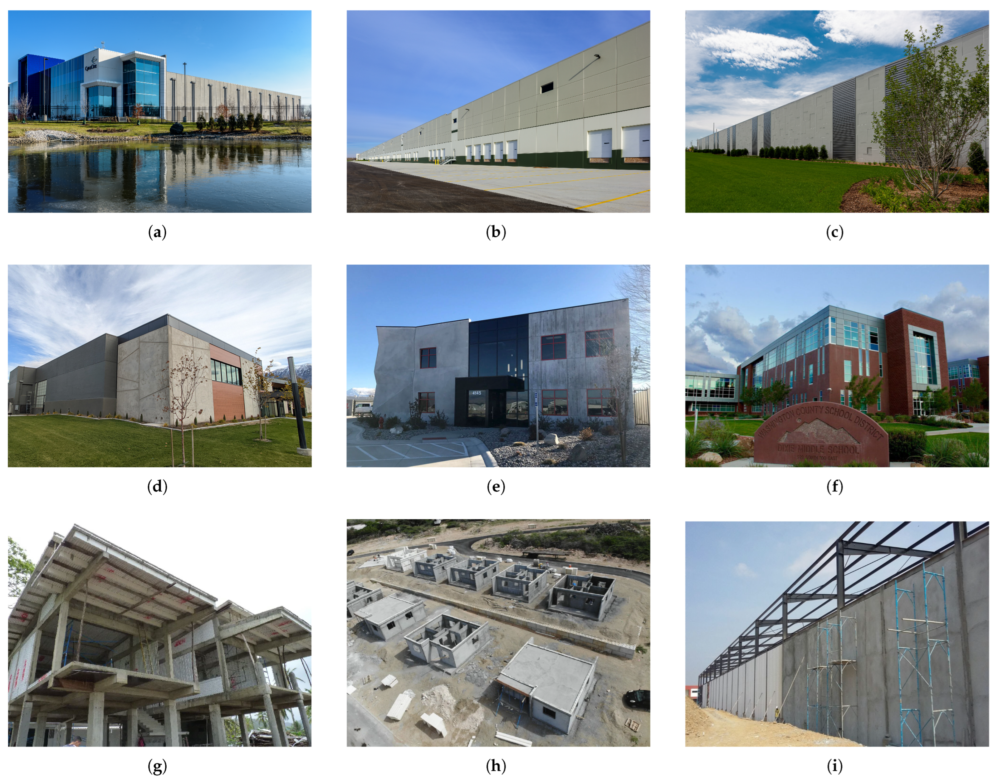
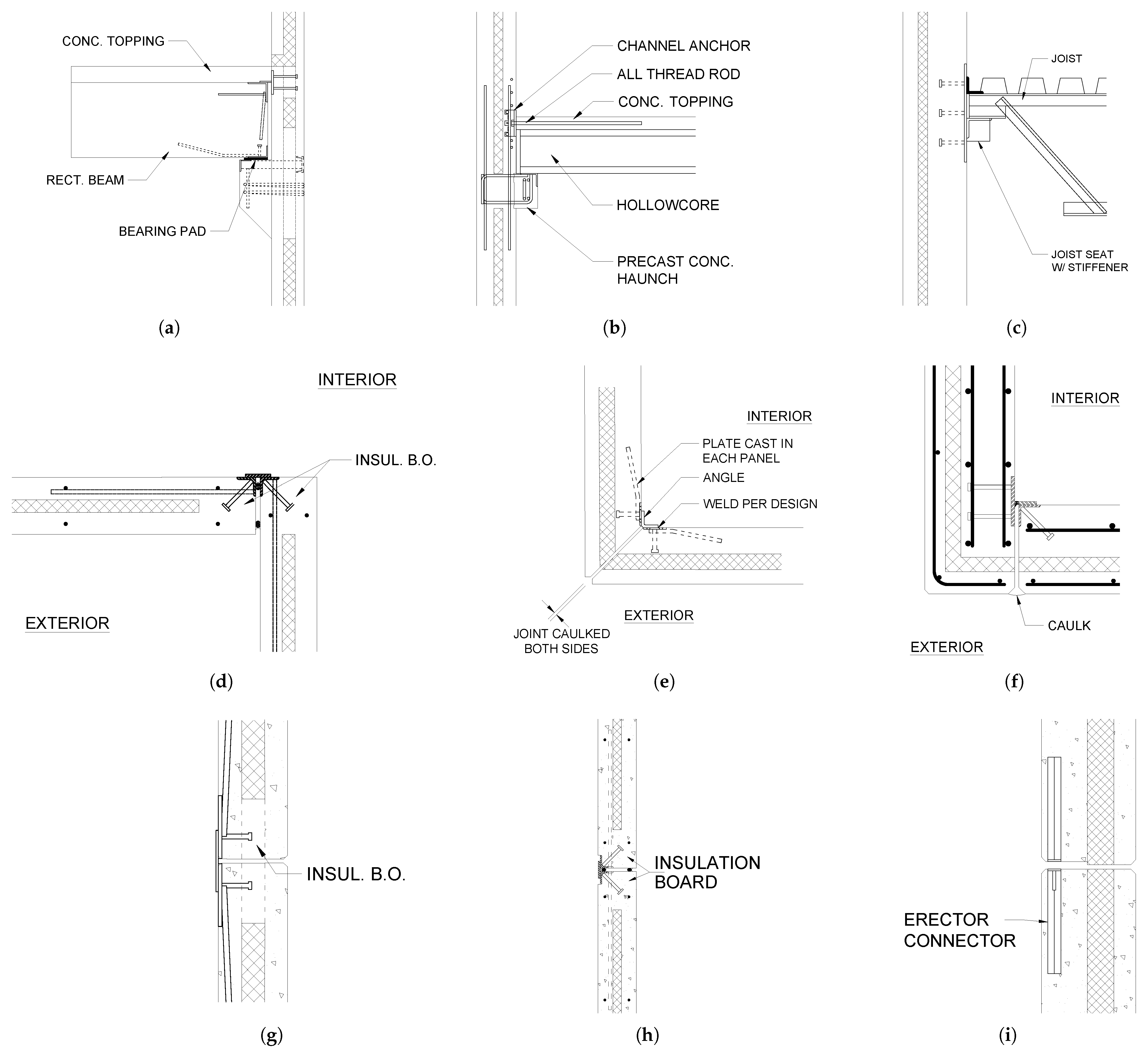
However, this does not preclude the use of CSWPs throughout the USA, Canada, and elsewhere in many building types, such as in commercial, residential, and storage buildings, where different construction techniques are used, such as precast (Figure 2a–c), tilt-up (Figure 2d–f), and cast-in-place concrete (Figure 2g–i). Recent research is alleviating the lack of codification by focusing on understanding the behavior of these panels when subjected to many loading types, including out-of-plane, axial, and, to a lesser extent, seismic.
This paper examines the existing literature and construction practices to present a comprehensive overview of the materials, design principles, and construction methods associated with CSWPs. To this end, the authors focus on the key materials used in constructing these panels and their characterization, the architectural and environmental considerations in designing CSWPs, the structural mechanics and design aspects, and the primary construction methods. These include the hardware required for installation (in the case of precast panels), as well as in situ casting techniques such as shotcrete and cast-in-place concrete.
This manuscript is organized into five main sections and conclusions. Section 2 details the materials and methods for characterizing CSWP wythe connectors. Section 3 discusses finishing types, thermal efficiency, moisture and condensation, and thermal detailing and performance. Section 4 analyzes structural mechanics under flexure, axial, and thermal loads, along with controlling loads and design methods. Section 5 explains the construction of precast, tilt-up, and shotcrete CSWPs and their advantages. Section 6 presents the conclusions and briefly discusses current research needs and future directions.

2. Materials Used in CSWP Construction

A key factor in the sustainability of CSWPs is their material composition, which directly impacts their structural performance, thermal efficiency, and long-term durability. By carefully selecting materials that enhance insulation, minimize thermal bridging, and resist environmental degradation, CSWPs contribute to energy efficiency and extended service life. The construction of CSWPs involves various materials, each crucial to the final product’s overall structural integrity and performance. As the introduction mentions, these panels have concrete, insulation board, and wythe connectors that bridge the concrete layers. This section discusses these materials in detail and explores which strengths are generally used in the industry and how they compare to the values typically tested in the literature.

2.1. Insulation Types

Insulation is one of the most critical parts of the CSWP system regarding thermal performance, as it provides a thermal barrier between a building’s interior and exterior. There are various organic and inorganic insulations on the market [21,22]. The three most commonly used insulation types in the construction of these panels are extruded polystyrene (XPS), expanded polystyrene (EPS), and polyisocyanurate (polyiso), with the latter typically used when the insulation’s thickness needs to be reduced at specific locations to accommodate embeds. Table 1 lists their R-value per inch (25 mm) and cost relative to the baseline insulation (EPS). The R-value is a measure of how well a two-dimensional insulator resists the conduction of heat. Although many other insulation types exist, they are not used as frequently as these three in CSWPs. Thus, they are not discussed in this manuscript.
The literature contains many tests to evaluate the thermal performance of CSWPs and the influence of insulation type and thickness. These studies have shown that greater insulation thickness can improve thermal efficiency, but this must be balanced against the increased structural demands on the concrete wythes because thicker insulation results in higher thermal resistance but lower composite action and overall ultimate strength of the connectors [23,24,25,26,27]. These studies have also shown that connector materials and insulation layout interruptions greatly reduce the thermal performance of panels. Therefore, it is paramount to reduce interruptions in the insulation to preserve its thermal properties.
Recent trends indicate the use of ever-thicker insulation to maximize thermal efficiency and reduce energy consumption, which poses new challenges that require further experimental investigation [27,28,29]. Few studies have examined the structural capacity of CSWPs with insulation thicknesses up to 250 mm, highlighting the need for further research on panels with insulation exceeding 100 mm [27]. However, it is important to note that the insulation thickness highly depends on the availability of wythe connectors to bridge such a gap. Since many connectors are proprietary, they have limitations on the insulation thickness they can efficiently span without negatively impacting their strength and stiffness, creating an opportunity to develop new connectors and refine the design of existing ones [27,30,31]. Moreover, other detailing and construction issues, like thermal bridges (see Section 3.2), also influence the effectiveness of the insulation when reducing heat transfer and condensation between the interior and exterior of buildings [24,32].

2.2. Wythe Connectors and Properties Characterization

Wythe connectors transfer interface forces between the concrete wythes and largely dictate the degree of composite action at which the panel will perform [9]. Commonly used connectors include steel truss systems, shear studs, and glass fiber reinforced polymer connectors [29,31,33,34,35]. Historically, steel connectors were the predominant choice due to their relatively low cost, ease of installation, material knowledge, and high percent composite attainment [12,36,37]. However, due to the high thermal conductivity of steel, the thermal performance of CSWPs significantly diminished, leading to the introduction of lower-conductivity materials such as carbon fiber-reinforced polymer (CFRP) and glass fiber-reinforced polymer (GFRP) in the 1980s [17].
Polymeric connectors have significantly reduced thermal bridges in CSWPs and have become the de facto choice for new constructions. However, not all fiber-reinforced polymer (FRP) connectors can provide the same strength and stiffness due to the various shapes and materials used for manufacturing. This wide variety is showcased in Table 2, which displays the common wythe connectors used in the construction of CSWPs with their respective base material, the type of composite action that can be achieved using them, and their type and some commercial brands associated with them. The most common type of connectors are discrete (individual) connectors, which are typically placed perpendicular to the surface of the concrete wythe to link them together. Less common alternatives include truss and grid connectors, typically made of GFRP or mild steel for truss connectors and CFRP for grid connectors.
The shear capacity of the connectors is one of the crucial parameters in determining the overall flexural and in-plane shear strength of the CSWP [38]. As such, it has received the most attention in the literature. However, not all the methods used to test and compare the shear strength of these connectors are standardized, leading to a wide range of conflicting results, even for the same connector type across different studies [30,39]. This lack of standardization creates a challenging environment for designers, as they must rely on proprietary information from manufacturers or conduct their own testing to characterize connector performance, which can be time consuming and expensive.
The available literature provides abundant experimental data and analytical models for characterizing wythe connectors’ strength, stiffness, and thermal performance [30,40,41,42,43]. Since CSWP interface forces act on connectors in three dimensions, manufacturers typically conduct tests to determine their axial and shear properties. The most popular testing types are single- and double-shear tests, which have different mechanics and provide different mechanical property values for a single connector. Syndergaard et al. [30] demonstrated that the values obtained from these tests differ vastly due to the moment exerted on the connector when tested in single shear (Figure 3a), which is minimal in a double shear test with more than one row of connectors (Figure 3b). This results in ultimate strength and stiffness values that differ by more than 20% between testing methods, making double shear tests the go-to method for sampling wythe connectors (Figure 3c). Cox et al. [44] developed a test setup to measure the axial load capacity of wythe connectors, a key property for designing panels subjected to out-of-plane suction loads. In addition to the structural resistance of wythe connectors, improved thermal resistance contributes to enhanced overall thermal performance, as discussed later in Section 3.

2.3. Concrete Wythes

The wythes in CSWPs use various cross-sectional shapes, thicknesses, concrete types, and concrete strengths. Three-wythe CSWPs are typically specified with three digits representing their geometry: outer wythe thickness, insulation thickness, and inner wythe thickness ( t o u t e r t i n s u l a t i o n t i n n e r , in mm) [19]. For example, a 75-50-200 non-composite panel would indicate a panel with a 75 mm thick outer facade, a 50 mm thick insulation layer, and a 200 mm thick inner structural wythe. These values vary depending on the construction method, type of composite action, and application. A similar convention is used for panels containing more than three wythes. Although panels are normally of uniform thickness, as evidenced by the vast literature, some precasters and researchers have used T-shaped cross sections to evaluate the structural performance of CSWPs [45,46]. Material-wise, the dominant concrete type for CSWPs is normal-weight concrete, with strengths ranging from 20 to 70 MPa depending on the construction method. Limited studies have explored the use of Ultra-High Performance Concrete (UHPC) [47]. In practice, cast-in-place panels typically have the lowest concrete compressive strength, tilt-up panels a medium one, and precast concrete panels the highest one, largely due to the incorporation of prestressing and crack-prevention design considerations.

2.4. Steel Grades and Types

Common materials for reinforcing the wythes include mild steel (up to 20 mm bars) and prestressing steel (up to 13 mm diameter strands) [39,46,48]. In some cases, such as the 3D Panel system, the wythes are reinforced with stainless steel bars that are part of the wythe connector system, and in infrequent occasions, such as when using UHPC, the wythes’ only reinforcement is steel fiber [47,49,50].

3. Architectural and Environmental Design

Concrete sandwich wall panels (CSWPs) are also increasing in popularity due to their versatility in both appearance and design, along with the inherent thermal and structural efficiencies they offer. In fact, CSWPs lend themselves well to sustainable building certifications like LEED or WELL [51]. These panels combine the functional benefits of insulation and thermal mass with a broad range of aesthetic possibilities, making them an excellent choice for sustainable construction. This section highlights the versatility of the appearance of CSWPs and the thermal benefits and natural resistance to condensation and moisture of the system.

3.1. Finishing Types

There is a common but mistaken perception that concrete structures are unattractive, often conjuring images of gray, featureless sidewalks or pavement. However, this view is far from accurate. In fact, many buildings people encounter daily, though made of concrete, are far from bland. Concrete sandwich wall panels offer a wide variety of finishes that make them not only functional but also visually appealing.

3.1.1. Surface Textures

The surface finishes on CSWPs influence their appearance, durability, and performance [52]. Additionally, since these panels often have two exposed faces, the finishes on both sides are important [52,53,54,55,56]. The most critical face, which is usually the exterior (outer face), is typically cast downward to take advantage of gravity, so that the exposed finish is smooth and even. The interior wythe (or top wythe) is generally finished using techniques that are applied to fresh concrete, such as screeding, floating, and troweling, and is often finally broomed, brushed, raked, rolled, or imprinted/stamped [57]. Because the exterior wythe is inaccessible during casting, additional finishing methods are often applied to the hardened concrete. A variety of surface textures can be created on CSWPs by modifying the hardened concrete’s surface, leading to smooth finishes, exposed aggregates, or even more complex structural looks (see Figure 4). All these finishes cater to diverse aesthetic preferences. The simplest option is to leave the panel “as cast”, which means the surface reflects the natural texture and look of the concrete as it comes out of the form. This finish is commonly used when an industrial style is desired or when the concrete itself is intended to be an accent [58].
Some finishes, like water washing, acid etching, or sandblasting, aim to expose the aggregate by removing cement mortar from the surface [59]. Water washing is the mildest, primarily cleaning the surface to expose naturally visible aggregate. Surface retarders can also be applied to prevent the outer layer from setting too quickly, enabling easier washing of the aggregate. Acid etching is a more aggressive technique, creating a slightly rougher texture that highlights sand and cement colors, though it requires special handling due to its environmental concerns. Sandblasting is the most aggressive of these methods, using pressurized particles to deeply penetrate the surface, leaving a rougher, more pronounced exposed aggregate texture. Conversely, instead of exposing the aggregate, the surface is sometimes honed or polished to create a smooth or reflective sheen [57]. This can provide a sharp, modern, professional appearance. Staining is another technique commonly applied to hardened concrete to modify its surface color. This is performed using different dyes or pigments that can help add flair to the concrete wall. The stains used tend to either be water-based or acid-based, though the latter exhibits greater resistance to fading over time.

3.1.2. Embedded Materials

Beyond surface treatments, CSWPs can incorporate embedded materials to enhance aesthetics. Thin brick is the most common embedded element, offering the appearance of masonry while maintaining the structural benefits of concrete. Thin brick is typically around 5 mm thick with a textured back that bonds well with concrete, providing a versatile design option that mimics traditional brickwork [60]. Similarly, natural and manufactured stones are also used in CSWPs, allowing for further aesthetic variety. Custom inserts, such as metals or ceramics, can also be added for unique design features. The manufacturing of CSWPs utilizing thin brick involves placing form liners into the forms that hold each brick in place during casting. Once the concrete cures, the form liners are removed and the panels are washed and finished to reveal what appears to be a brick wall.

3.1.3. Formwork-Driven Designs

Custom form liners are becoming more common, and advances in CNC machining and rubber form liner technology facilitate this. These techniques enable the creation of panels with custom patterns, shapes, and textures, including wood grain and geometric shapes. Additionally, large-scale imagery and motifs can now be created with precision using form liners or stencils. Joint patterns can also be used to create a visual rhythm or accentuate particular areas. The use of 3D printing is also gaining popularity for creating custom shapes and intricate designs for CSWPs, with the potential for reducing waste and decreasing production time [61].

3.2. Thermal Efficiency

One of the primary benefits of concrete sandwich wall panels is their exceptional thermal performance, primarily due to the insulation layer sandwiched between two layers of concrete [62]. CSWPs provide continuous insulation, improved R-values, long-term resistance to insulation degradation, and the added benefits of thermal mass, which moderates temperature fluctuations and offsets peak heating and cooling demands. These advantages make CSWPs highly thermally efficient.
Beyond their inherent thermal benefits, CSWPs also play a crucial role in modern thermal engineering for both new construction and retrofitting existing buildings. In new designs, careful selection of insulation type, thickness, and connector materials optimizes energy efficiency and ensures compliance with increasingly stringent building codes. For retrofits, CSWPs offer an effective solution for enhancing thermal performance in aging structures, reducing energy consumption, and improving occupant comfort without extensive modifications to the existing framework [63,64]. These factors highlight the importance of thermal engineering considerations in maximizing the efficiency and sustainability of CSWP-based construction [65].

3.2.1. Continuous Thermal Resistance

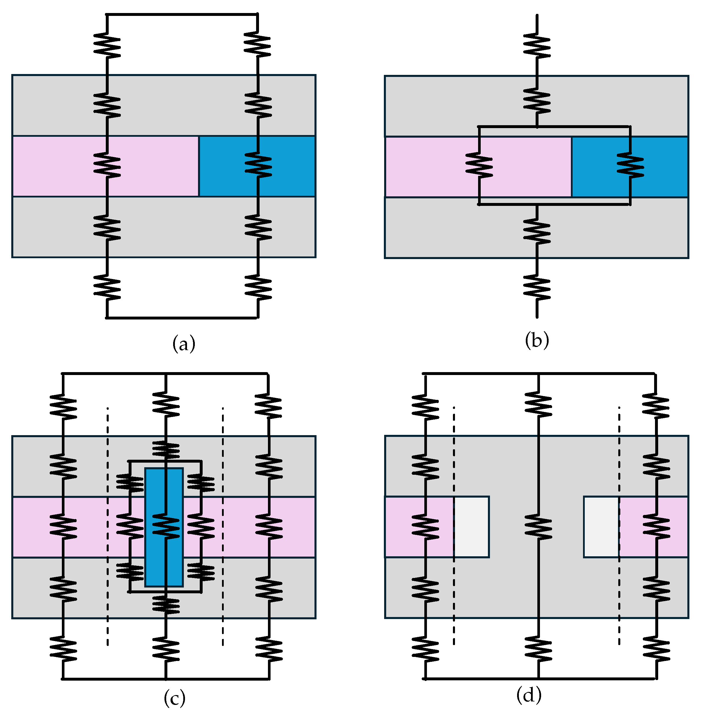
CSWPs facilitate continuous insulation throughout the building envelope, which is defined by the 2024 International Energy Conservation Code (IECC) [40] as “insulating material that is continuous over all structural members without thermal bridges other than fasteners and service openings”. The insulation in CSWPs is placed in the middle of the system, effectively increasing thermal resistance by reducing thermal bridging. Energy codes commonly rely on the steady-state heat flow properties of materials, such as R-values (thermal resistance) and U-factors (thermal transmittance), to compare materials and systems [61,66,67]. The integration of insulation into the structural system naturally enhances the thermal resistance of CSWPs, making them highly efficient in preventing heat loss. Several methods have been developed to calculate the thermal efficiency of concrete sandwich wall panels, including the parallel-path method, the isothermal-planes method, the zone and modified zone methods, and the characteristic section method [19]. These methods account for changes in thermal conductivity, similar to how electricity flows in a circuit (Figure 5).
  • Parallel-Path Method (Figure 5a): This method assumes heat transfer occurs along various paths, with each path having its own resistance. The total resistance is the inverse of the sum of these resistances, calculated by the weighted areas for each path [67].
  • Isothermal-Planes Method (Figure 5b): This method treats entire homogeneous layers as a single resistance value, only splitting paths where different materials are present [19].
  • Zone and Modified Zone Methods (Figure 5c): These methods account for areas with high-conductivity thermal bridges, such as steel connectors, and break the panel into “zones” that consider the variations in thermal resistance. Each zone, designated by the dashed lines in Figure 5c, is considered a separate path, which is combined together using the same methodology as the parallel-path method. In order to improve the accuracy of the zone method, Lee and Pessiki [68] created the modified zone method, where the only difference lies in how the zone width is determined (i.e., the distance from the thermal bridging element at which the zone boundary, marked by the dashed line, is defined).
  • Characteristic Section Method (Figure 5d): This method, developed by Lee and Pessiki [69], refines the modified zone method to better address areas with large solid sections, ensuring accurate thermal calculations. This model is empirical and accounts for some lateral heat transfer by assuming a slightly enlarged solid area, as shown in Figure 5c, where the insulation within the defined zone is ignored (i.e., the grayed-out portion of the figure). Among the four methods, this is the most accurate for evaluating CSWP thermal performance.
Structures are continually subjected to daily temperature fluctuations, which can vary significantly depending on climate and season, with some locations experiencing temperature swings of up to 50 °C within a 24 h period [70]. In addition, thermal performance can change based on weather and seasonal effects. Table 3 shows a comparison of the R-value results for winter and summer according to different insulation thicknesses [27]. Despite these variations, energy codes typically rely on steady-state properties to compare materials, as these simplify calculations and provide a reasonable approximation of average heat flow over time for non-mass structures. While CSWPs perform well under steady-state conditions, these measures do not fully capture the dynamic thermal behavior of concrete structures, often resulting in conservative estimates of their thermal performance [71]. This discrepancy highlights a key advantage of CSWPs: the thermal mass effect.

3.2.2. Thermal Mass

According to Losch et al. [19] CSWPs excel at providing passive heating and cooling due to their high thermal mass, which is the ability of a material to absorb, store, and release heat. Concrete naturally has a high specific heat, low conductivity, and high density, which allow it to absorb energy with little temperature fluctuation, especially compared with other materials such as steel or wood [58]. This characteristic enables concrete to store and delay heat transfer, absorbing heat temperature fluctuations far better than materials like steel or wood. This characteristic enables concrete to delay heat transfer, absorbing heat during the day and gradually releasing it at night. As a result, CSWPs help maintain more consistent indoor temperatures, reducing heating and cooling demands [58]. By incorporating insulation layers on both sides of the concrete, CSWPs amplify this benefit, offering enhanced thermal stability and increased occupant comfort.

3.2.3. Thermally Efficient Detailing and Performance
Thermal efficiency is the ability of a building envelope to minimize energy loss and maximize energy use for heating and cooling. It reflects how well a structure retains heat in winter and stays cool in summer, reducing the energy required for temperature regulation. Testing the effect of connectors on the CSWP system is paramount for determining the overall thermal performance of these panels. Some studies have been performed by a limited amount of researchers who have used temperature measurements and finite element modeling to assess the thermal resistance and thermal bridging of various connector types.
Studies by Lee and Pessiki [23] and Sorensen [62] have delved into the computation of the thermal performance of CSWPs using analytical and finite element models. In contrast, studies by Kim and Allard [24], Woltman et al. [25], Yu et al. [72], and O’Hegarty et al. [26] have quantified the thermal resistance of panels experimentally. These studies have demonstrated the impact of connector material and layout on the overall thermal performance of CSWPs, with steel connectors being the worst performers and FRP connectors being the most effective at reducing thermal bridging to virtually eliminating it. These studies also highlight the need for more thermal testing to quantify the effect of different connector types, materials, and typical structural details on the thermal resistance of CSWPs. As highlighted by O’Hegarty and Kinnane [61], much of the literature has quantified thermal performances below modern building code standards. New detailing, materials, and configurations may be needed to overcome this issue.
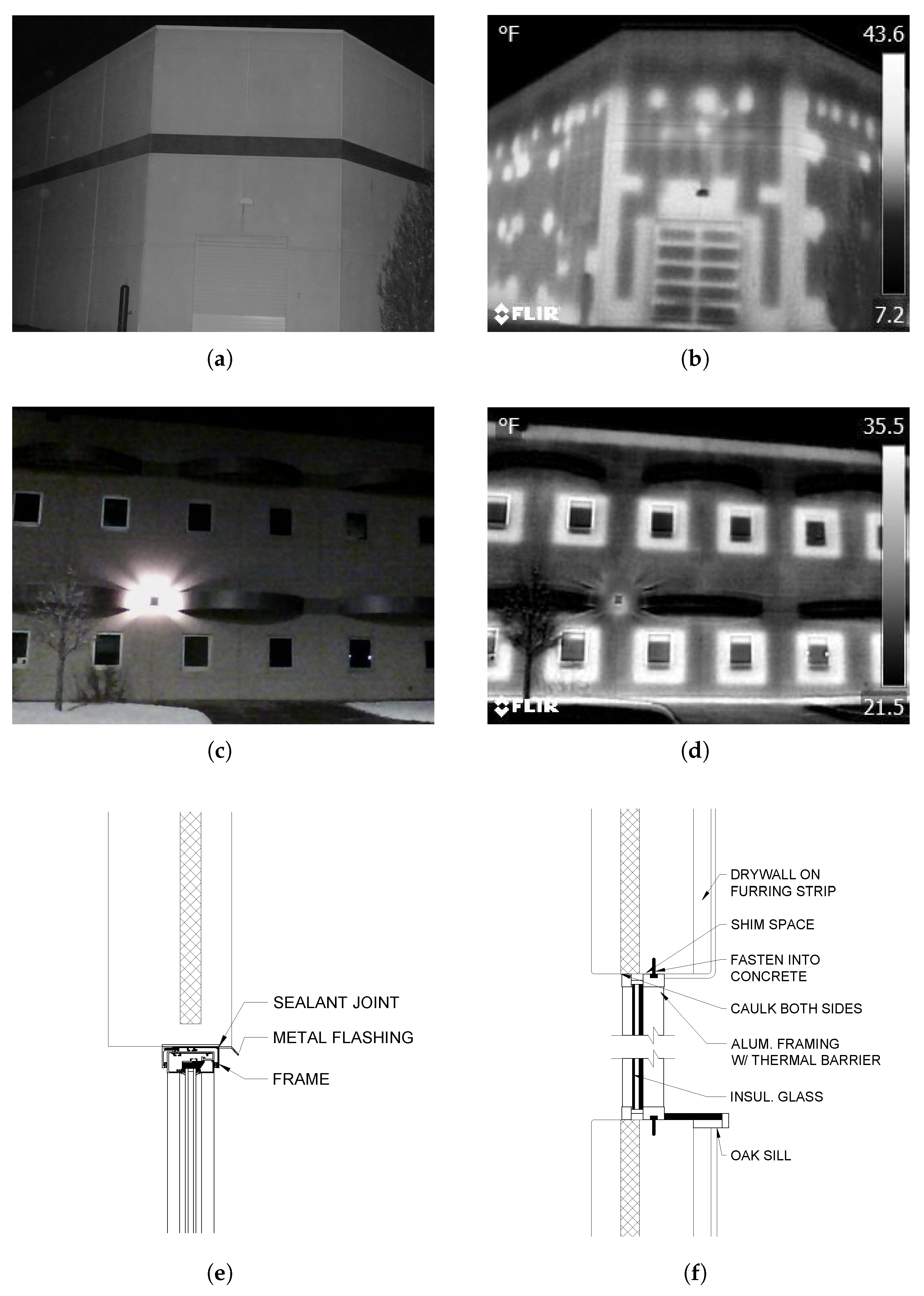
Research has demonstrated the excellent potential for thermal performance in CSWPs, but this can be significantly influenced by detailing. Thermal bridging occurs when the continuous insulation is interrupted by solid sections or penetrations of thermally conductive materials. Common locations of heat loss include fenestrations, lifting points, corbels, roof and floor terminations, panel-to-panel and foundation connections, corners, insulation joints, and metal SWP connectors [32]. Figure 6 provides examples of thermal bridging due to poor detailing at these locations. Structural connections, particularly those transferring loads, are especially vulnerable to heat loss due to the creation of thermally weak points.
However, innovative detailing can mitigate these issues and enhance both structural and thermal performance. For example, Figure 6e,f compares two CSWP window details: one with a solid section around the window, resulting in significant heat loss, and another maintaining continuous insulation designed to minimize thermal bridging. Similarly, studies on corbel connections between floors and walls have shown that thermal bridging can be avoided using FRP connectors [28,73]. These solutions often utilize standard materials available on-site and require no specialized products [73]. Ultimately, to address thermal efficiency and improve condensation prevention, engineers must prioritize designs that not only ensure structural safety but also minimize thermal bridging. This requires a shift in paradigm. Maintaining continuous insulation with minimal interruptions is the key to improving energy efficiency and reducing heat loss.
Figure 6. Photos of thermally inefficient detailing effects on the thermal performance (ad) and typical window details, (e) with solid section and resultant thermal bridging around the edge of fenestration and (f) with continuous insulation to the edge of fenestration, mitigating the thermal bridge through the structural element [62,74].
Sustainability 17 03704 g006

3.2.4. Long-Term Thermal Performance and Durability

The sandwich structure of CSWPs provides long-term protection for the insulation. The concrete layers serve as durable barriers, shielding the insulation from environmental factors such as weather, temperature fluctuations, and moisture, which can otherwise cause degradation. Additionally, CSWPs are less susceptible to damage from external forces like pests or accidental punctures, ensuring the insulation remains intact over extended periods. This contributes significantly to the overall longevity and durability of the system, reducing the carbon footprint by extending the structure’s lifespan [53].
The choice of connectors in CSWPs also plays a crucial role in their durability. Historically, steel connectors were commonly used, but they significantly undermined the thermal benefits of CSWPs. While steel connectors offer high strength and stiffness, they create severe thermal bridging [32] and are prone to corrosion over time, particularly in high-humidity environments. Corrosion is one of the greatest challenges to the long-term durability of CSWPs, reducing service life and increasing maintenance costs [75,76]. Although steel connectors are still used in some applications today, a preferred alternative is using fiber-reinforced polymer (FRP) connectors.
FRP connectors, available in various types based on the fiber material—such as glass (GFRP), carbon (CFRP), aramid (AFRP), and basalt (BFRP)—offer superior thermal performance while maintaining comparable strength to steel [77]. These connectors are now the industry standard for CSWPs, as they not only enhance structural and thermal performance but also increase overall durability. Additionally, hybrid steel–FRP connectors have recently emerged on the market, offering a balance between the strength of steel and the thermal efficiency of FRP [78].

3.3. Moisture and Condensation

Moisture is a significant concern in many building types as it can lead to structural damage, mold growth, reduced insulation performance, and health problems [58]. Condensation often forms around thermal bridges, where temperature differences cause moisture to accumulate. CSWPs, however, are well-equipped to mitigate many moisture-related problems. By incorporating continuous insulation, CSWPs minimize thermal bridging, reducing the risk of condensation [79]. Additionally, the use of low permeability concrete can provide natural resistance to moisture intrusion, while the airtight construction of CSWPs enhances control over moisture flow, preventing buildup and condensation [80]. This design reduces the risk of mold growth, improving indoor air quality. Consequently, CSWPs not only enhance thermal efficiency but also contribute to a healthier, more comfortable indoor environment, aligning with sustainability goal 11 (Sustainable Cities and Communities).

3.4. Life Cycle Assessment and Sustainability

CSWPs offer significant sustainability advantages throughout their life cycle. Life cycle assessments (LCA) consistently demonstrate that CSWPs reduce both embodied and operational carbon emissions compared to alternative wall systems. The majority of a CSWP’s environmental impact occurs during the early stages of its life cycle, including raw material extraction, transport, production, and installation [81]. However, CSWPs offset these initial impacts through their long service life, reduced maintenance needs, and superior thermal performance, which lowers energy demand for heating and cooling over the building’s lifespan [65].
Studies show that CSWPs have a lower environmental impact than traditional brick veneers [82], solid precast or cast-in-place concrete panels [83], and lightweight composite insulation panels such as aluminum–polyurethane systems [81]. Additionally, CSWPs exhibit extended durability compared to wood-framed structures, further reducing life cycle environmental impacts [84]. Their high thermal mass optimizes solar gain benefits, mitigates temperature fluctuations, and reduces peak heating and cooling loads, improving overall energy efficiency [81].
The use of supplementary cementitious materials, such as fly ash, has been shown to further decrease embodied carbon and energy demand [85]. Emerging research on incorporating recycled aggregates and alternative insulation materials presents opportunities for enhancing sustainability even further [81,84]. The potential for reusability and recyclability at the end of life also contributes to the circular economy, making CSWPs a compelling choice for sustainable construction [81], aligning with sustainability goal 12 (Responsible Consumption and Production).

4. Structural Mechanics and Design

The structural mechanics and design of CSWPs are not yet well understood or codified, mainly due to the lack of consensus among stakeholders. Current industry practices rely heavily upon prescriptive methods guided by the connector manufacturer, which dictates the composite action limits for their wythe connectors [9,86]. New methods involving both analytical and finite element approaches have recently been developed to address these limitations [20,45,87,88,89]. Still, significant gaps remain in understanding the complexities of CSWP behavior, particularly in the nonlinear range, the interaction of multiple load types, and the effects of multi-span behavior on connectors. This section treats the current state of research on the structural mechanics and design of CSWPs, including testing conducted and open opportunities to advance their understanding.

4.1. Panel Mechanics

4.1.1. Elementary Behavior

The configuration and the materials used to construct CSWPs make them a unique structural system. These panels can exhibit varying amounts of composite action between wythes but are typically classified in one of three categories: non-composite, partially composite, or fully composite [19]. In a purely non-composite system, the concrete wythes act independently, meaning the section’s moment of inertia is the sum of the individual wythes. However, this is unrealistic in CSWPs due to the presence of wythe connectors. At the other extreme, fully composite behavior assumes a perfectly rigid connection that enables a continuous strain profile under load—an idealization that is nearly unattainable with current technology. Unlike steel–concrete composite beams, CSWPs typically behave between the partially composite and nearly non-composite range due to the flexibility of their wythe connectors and the gap created by the insulation board [45,90].
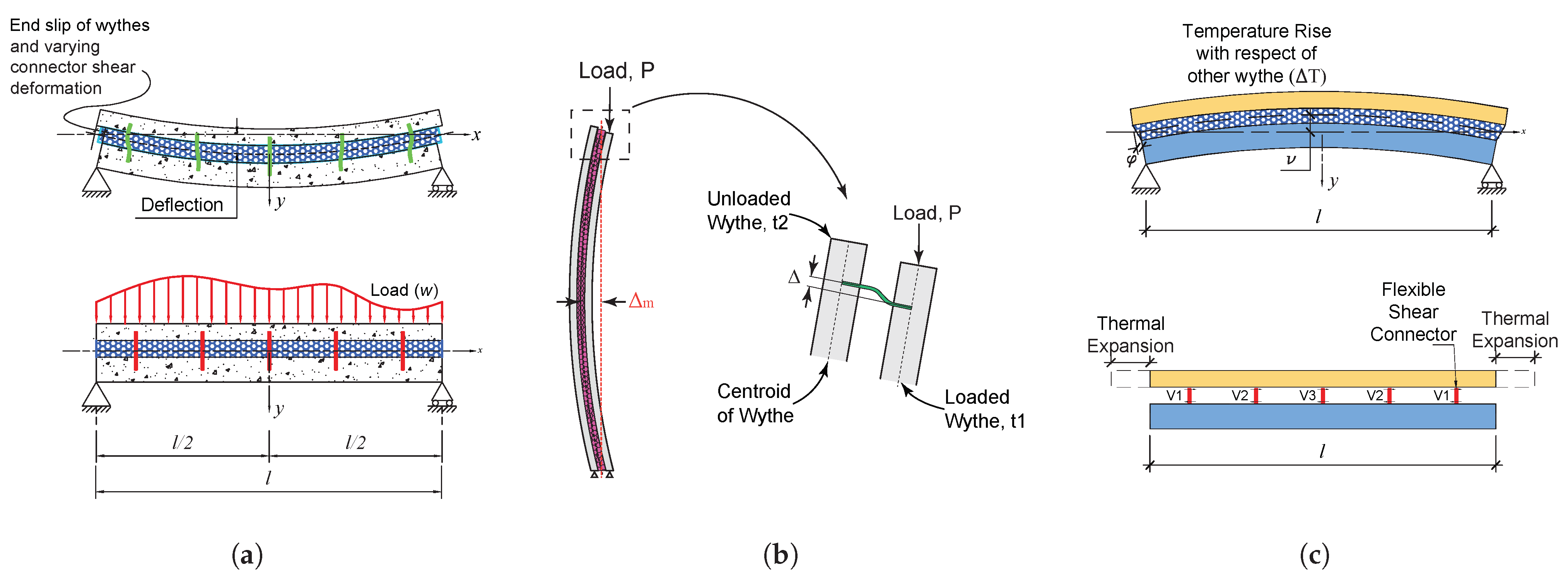
The three most common forms of loads acting in CSWPs are out-of-plane distributed loads [39,86], axial loads [91,92], and temperature loads [93,94]. Other loads, such as blast and impact, are less common but produce a similar effect as the loads mentioned above, with the exception of seismic loads, whose effect on the panel mechanics has not yet been studied. Figure 7a shows a uniformly loaded panel and its corresponding deformed shape. When the deformation occurs, not only the panel deflects but also its concrete wythes displace (slip) relative to the others, making the panel ineligible for the typical assumption that “plane sections remain plane after the deformation” used in designing many composite members. This slip has flexural and axial components, which have been described in detail by Holmberg and Plem [13], Bai and Davidson [38,89], and Al-Rubaye [48]. However, there is still a need for exploring this type of behavior in multi-span panels [95].
Axial loads from the roof and intermediate floors are often applied with significant eccentricity to the panels, generating flexural moments at the floor and roof connections [96]. This loading, as depicted in Figure 7b, produces a P-delta ( δ ) effect on the panel and generates a slip that deforms the connector in a way similar to a panel in flexure. Despite this complexity, much of the testing in the literature has focused on concentrically loaded panels or panels with very small eccentricities, leaving a significant gap to explore [97,98,99,100].
CSWPs also experience thermal deformations due to the temperature gradients formed between the interior and exterior of buildings. Researchers began investigating and explaining these mechanics as early as 1965 [13]; however, this research was not validated until recently [93,101]. When panels deform due to thermal gradients, as shown in Figure 7c, the axial expansion (or contraction) of the panel is restricted by the wythe connectors and, in turn, the panel deforms in an out-of-plane manner. Some industry experts have anecdotally rejected this structural behavior, despite several large-scale tests confirming its existence [94,102,103] and the large strains it imposes on wythe connectors.

4.1.2. Behavior up to Failure

CSWPs are primarily loaded in flexure and, due to their aspect ratio (normally above 2), behave like one-way members. Even when used in structural applications, code-imposed limits on axial loads (typically below 10% of their capacity) ensure they continue to behave like one-way flexural members [86]. In the case of squat sandwich walls, there is still a lack of research and testing to study their behavior and the effect of two-way action on the wythe connectors. The literature identifies three well-characterized panel behaviors: (i) horizontal shear under-designed panels, (ii) horizontal failure-controlled panels, and (iii) concrete wythe failure-controlled panels [24,86,104,105,106,107]. Figure 8 shows the load–displacement curves for each of these behaviors.
In the first case, one of the wythes cracks, leading to a failure of the wythe connectors and a significant drop in load-carrying capacity to well below the panel’s design ultimate strength. The second case exhibits similar behavior, but both concrete wythes crack and the steel reinforcement engages significantly until the connectors fail abruptly, reducing the overall load-carrying capacity. Alternatively, the concrete may crush beforehand, which also results in a brittle failure. In the third case, the panel’s reinforcement fully yields and strain hardens until either the concrete crushes, the steel ruptures, or the connectors fail in horizontal shear.

4.2. Design Loads

4.2.1. Dominant Loads and Load Combinations

In service, CSWPs are primarily subjected to a combination of out-of-plane and in-plane loads, plus thermal gradients [19]. Out-of-plane loads arise from wind and seismic actions, axial loads result from self-weight, dead loads, live loads, and snow, while thermal loads stem from the thermal expansion and contraction of concrete. As mentioned earlier, the out-of-plane loads control the design of these panels, requiring them to be designed for flexure and point loads resulting from the support of roof members.
The load combinations listed in the set of Equation (1) (ASCE 7 load combinations [108]) and any other load combination list typically require the incorporation of “self-straining forces and effects” (e.g., thermal gradients) due to their magnitude and potential adverse effects on structural stability; however, the load factor value is still not known for CSWPs. Firstly, there are few studies dealing with thermal gradients in structures, and secondly, there is a lack of understanding of the thermal effects combined with other loads in CSWPs. Nonetheless, this factor should never be less than 1.0, as recommended in ASCE 7 [108].
1.4 D 1.2 D + 1.6 L + 0.5 L r or S or R 1.2 D + 1.6 L r or S or R + ( L or 0.5 W ) 1.2 D + 1.0 W + L + 0.5 L r or S or R 0.9 D + 1.0 W 1.2 D + E v + E m h + L + 0.2 S 0.9 D E v + E m h
where D is the dead load, E m h is the horizontal seismic load, E v is the vertical seismic load, L is the live load, L r is the roof live load, R is the rain load, S is the snow load, and W is the wind load.
The design of CSWPs is governed by different load combinations depending on the structural role and environmental exposure of the panel. The load combination 1.4 D typically controls gravity-only conditions, such as stripping, lifting, handling, and erection. The combination 1.2 D + 1.6 L + 0.5 ( L r or S or R ) often governs for panels supporting live loads, such as those located at floor levels or supporting occupied roofs. When roof panels are subjected to snow, rain, or roof live loads, particularly in northern climates or high-ceiling warehouses, the combination 1.2 D + 1.6 ( L r or S or R ) + ( L or 0.5 W ) may be controlling. For panels exposed to lateral wind combined with gravity loads, such as those used for the building envelope in wind-prone regions, the combination 1.2 D + 1.0 W + L + 0.5 ( L r or S or R ) tends to govern. In cases where wind suction causes uplift, particularly in roof panels with limited gravity load, the combination 0.9 D + 1.0 W becomes critical for designing the panel connection to the roof and foundations. In seismic regions, the combination 1.2 D + E v + E m h + L + 0.2 S controls the design of panels that contribute to the lateral force-resisting system. Lastly, the combination 0.9 D E v + E m h governs seismic uplift and overturning checks, especially in tall, slender panels or those resisting large seismic forces.

4.2.2. Design Load Challenges

Three common design load challenges arise when designing CSWPs. The first is to design panels for point loads in service (from roofs and intermediate floors) and during lifting [96]. Currently, there is limited information on the behavior of these panels under such loads and guides like PCI-150 [109] rely heavily on construction practices and engineering judgment to estimate these loads and suggest solutions to prevent localized failures. The second design load challenge concerns seismic loading and panel behavior when they are subjected to cyclic loads. Although there is limited information on the behavior of these panels in seismic areas, as discussed later in this article, they are still occasionally used in seismic zones. In such cases, engineers typically use steel rebar and solid concrete sections to transfer large loads between the concrete wythes instead of FRP connectors. This approach ensures load transfer and can improve ductility and strength, but it comes at the expense of thermal performance.
Thermal loads also pose unique challenges, especially for extremely cold or hot regions in a world threatened by climate change. In the authors’ experience as consultants, in regions such as the northern United States and Canada, thermal gradients often reach −40 C in winter and 20 C in summer, causing the flexural moments due to thermal gradients to exceed the design moment for wind. This, in turn, makes a combination of Wind + Dead + Thermal extremely difficult to handle without significantly interrupting the insulation or increasing the thickness of the concrete wythes. However, the former defeats the purpose of building a CSWP due to the generation of thermal bridges and the latter significantly increases the cost and seismic weight of the structure. Therefore, studying CSWPs under the combined effects of thermal, wind, and axial loads is essential to enhance the structural safety of these panels and better understand their mechanics.

4.3. Design Methods

There are many continuous and discrete methods to design CSWPs, most of which have been developed for designing simply supported panels predominantly loaded in flexure. Table 4 shows a list of methods that can be used to design CSWPs in the elastic [13,48,110,111,112,113] and inelastic ranges [19,44,87,88,114,115]. Since precast CSWPs are designed to remain crack-free in service, the accuracy of the elastic methods is paramount to preserve the architectural integrity of these panels. Conversely, methods that accurately capture the non-linear behavior of these panels assist the industry in designing for ultimate loads with minimal concern. However, only the percent composite method and the beam–spring model (BSM), due to its versatility, have been fully implemented in design software such as LECWALL [116] and ERIKSSON WALL [117], as discussed in the following sections.

4.3.1. Beam–Spring Modeling

Beam–spring modeling, as shown in Figure 9, is a discrete methodology used to design CSWPs subjected to any loading type with any support condition that uses beam elements to represent the concrete wythes and spring elements to model the wythe connectors and insulation [20,87,118]. However, using beam and spring elements to model structural behavior is not unique to CSWPs. Many other researchers have implemented this approach to model the loading response of reinforced concrete [119], prestressed concrete [120], steel–concrete composite [121], and timber–concrete composite members [122]. The key parameter in all cases is the stiffness of the spring, which is responsible for transferring interface forces from one element to the other.
In CSWPs, the stiffness of the wythe connector is modeled after a single or double shear test, as discussed in Section 2.2, out of which a backbone curve is built to capture the entire load versus displacement behavior of the wythe connector [30,42,43,123]. The second most relevant parameter is the selection of a proper concrete model to capture the non-linear behavior of the concrete wythes, which are normally lightly reinforced and have tensile and compressive forces acting on each opposite wythe. Many authors have implemented different models to capture the response of concrete wythes. Gombeda et al. [87] used a Linear Tension Softening model to represent the concrete behavior of the wythes [124] and an elastic multi-linear material to model the steel reinforcement. Al-Rubaye [90] recently studied the suitability of different concrete models for accurately predicting the structural response of CSWPs subjected to combined flexure and axial loads, finding out that the model by Torres et al. [125] best reflects the concrete wythes’ behavior post-cracking.
Figure 9. Illustration of a beam–spring model and its parameters [126]. Illustration by the authors.
Sustainability 17 03704 g009

4.3.2. Percent Composite Analogy Method

The percent composite analogy method is a widely used approach for designing CSWPs, based on the idea that a panel’s behavior falls somewhere between the two idealized extremes: fully composite (100% composite action) and non-composite (0% composite action). In reality, panels exhibit a partial degree of composite action, meaning the wythes act together to some extent but not entirely. This relationship is often assumed to be linear, allowing for interpolation between the two extremes to determine the actual degree of composite behavior. Thus, the term “percent composite action” refers to the ratio of a panel’s actual composite behavior relative to these two idealized states.
To apply this concept in design, factors are introduced to convert a sandwich structure into an equivalent solid panel for calculating stresses and deformations, with separate factors for each [9,19]. This method relies on experimentally determined percentages of composite action in both the elastic and inelastic ranges for a given connector concentration per area. However, because the composite action depends on multiple variables, connector manufacturers and precasters often prescribe single values for standardized wythe connector spacings, neglecting the influence of panel length, insulation thickness, and concrete wythe thickness on the overall panel performance.
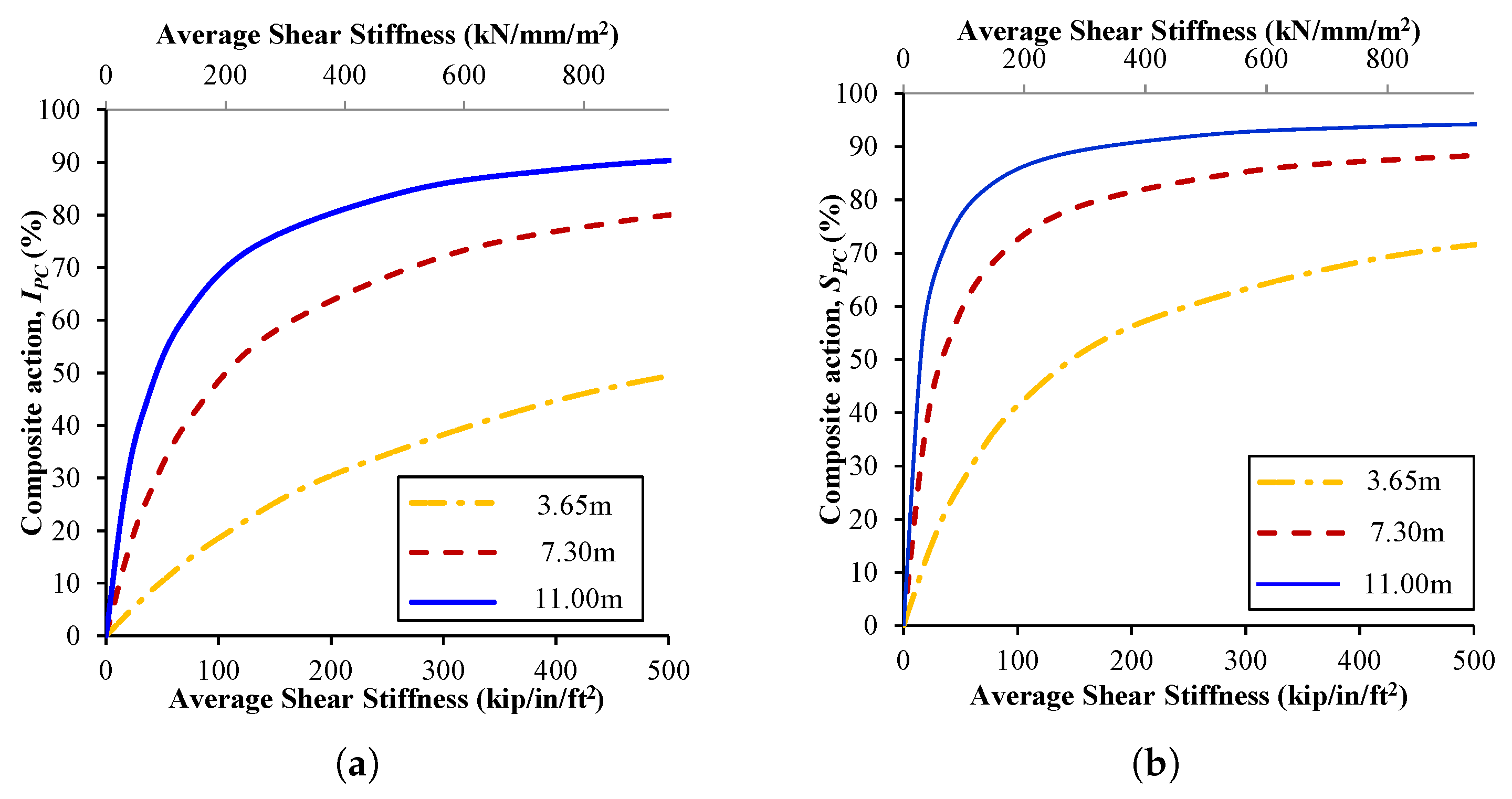
Figure 10 shows the variation of the percentage of composite action as a function of the average shear stiffness per area of the panel (sum of connector shear stiffness divided by the area of the panel) for three different panel lengths with a 75-75-75 configuration and modeled using the BSM. As reflected in both figures, the percentage of composite action varies depending not only on the average shear stiffness but also on the length of the panel, and the percentage of composite action is different for computing deflection versus computing stresses, creating challenges when trying to use this method in a design setting. On the one hand, using different values of the percent composite action for different computations can lead to design errors; on the other hand, using a single value for the percentage composite action for different panel lengths can produce both conservative and unconservative structural designs. Moreover, this analogy prevents engineers from grasping the understanding of the fundamental panel mechanics and the structural behavior.

4.3.3. Other Design Methods

As mentioned earlier, other methods for designing CSWPs exist; however, they are not routinely used in design firms due to limitations related to loading types, support conditions, or simply a lack of public exposure [13,45,59,87,89,101,110,112,115,127]. In fact, most methods have only been developed for simply supported panels and are unable to capture connector behavior over intermediate supports in hyperstatic structures. These methods can be roughly grouped as discrete or continuous and can also be separated by their ability to predict linear or non-linear behavior. Discrete methods model the connectors as individual units spread along the panels, whereas continuous methods consider the wythe connectors as a continuum medium uniformly distributed along the length and width of the panel. On the other hand, linear methods do not have the ability to predict the behavior of the panel beyond cracking, making them unusable for computing cracked-section deformations, which are paramount in the design of structural panels.
Most modern connectors are made of individual FRP or metallic pieces, with the exception of the grid and truss wythe connectors, such as the C-grid system [128] and NU Tie [18]. Therefore, continuous methods like the ones developed by Holmberg and Plem [13], Allen [110], and Timoshenko [113] are unable to capture their behavior accurately. In addition, these methods are also restricted to the linear range and simple span panels. In contrast, discrete methods [48,87,111,112,114,115] can handle any connector type, including continuous ones if their properties are lumped into discretely spaced connectors. However, some of them are exclusively restricted to the linear range [48,112].
These methods also have the limitation of not being verified using large-scale panel testing datasets. This is because much of the testing in the literature restricts access to its data or because researchers often do not sample the wythe connector properties separately before using them in panels. In addition, many tests do not measure the end slip or strains at several locations along the panel, both of which can be used to validate design methods. Although the vertical deflection reflects the level of composite action, it does not capture all the mechanisms that take place during a sandwich structure deformation [13,110,127,129,130,131]. Al-Bayati [132] presented the first study dealing with the problem and identified several shortcomings of both the testing (unpredictable performance) data and linear design methods (high scatter). Al-Bayati [132] also recommended bias factor, coefficient of variation, and probability functions to model the cracking load and deflection at cracking of CSWPs.

4.3.4. Wythe Connector Design Layout

Another important aspect in designing CSWPs is the distribution of wythe connectors, which has been shown to influence composite action and overall panel performance. Most researchers have studied CSWP behavior using uniformly spaced connectors (see Figure 11a), while few studies have explored the effect of lumping the connectors at the end, such as the one displayed in Figure 11b,c.
Gombeda et al. [106] explored hybrid and end-heavy wythe connector distribution strategies to investigate the change in the degree of composite action for a comparable uniformly connected panel. Similarly, Cox et al. [44] implemented an end-heavy wythe connector distribution to study the increase in composite action of the panel. Both of these studies demonstrated the effectiveness of lumping connectors near the ends instead of using them at locations where interface forces are minimal. More research is needed to quantify these effects across other connector types, especially for very stiff connectors due to concerns of concrete breakout failures, as seen in the study by Cox et al. [44].
Although researchers may think this practice is new or novel, eliminating a few connectors near the center of the span of a panel is a typical steel industry practice, for example the steel studs in steel–concrete composite beams are concentrated near the ends of the member. The rationale behind this approach is that shear connectors experience minimal interface forces near the mid-span and maximal ones near the ends of the panels. Only discrete methods can accurately capture this, whereas continuous methods may yield inaccurate results, as shown by Cox et al. [44]. The most common form of dealing with this issue is to implement a discrete method and lump the sum of the stiffness of the wythe connectors in a given row.

4.4. Testing Conducted in the Literature and Its Relation to Industry Needs

The CSWP literature includes many large-scale tests with different boundary conditions, loading types, and span lengths. Table 5 presents a summary of the testing conducted on CSWPs in out-of-plane bending, compression, thermal, and seismic loading. As this table shows, most testing has been conducted on panels in flexure using mild steel, with minimal testing on prestressed concrete panels, although these are some of the most used ones.

4.4.1. Flexural Tests

Much of the testing in the literature has been conducted on short-span panels, with few tests conducted for panels of 10 m long or more [86,133], despite of the fact that most CSWP buildings (at least in North America) are taller than 10 m. The first comprehensive CSWP testing program was conducted by [12] in the 1960s, applying a distributed load with an airbag on panels using steel connectors, such as trusses and grids, and different insulation types. Although these panels were short, they exhibited high degrees of composite action due to the high stiffness of their connectors. After that, many tests were later conducted focusing on prestressed panels using different lengths, connector types, and load application methods (airbags, water bladders, and three-point bending) [28,36,37,39,46,133,134].
Still, researchers and the industry have continued focusing on developing wythe connectors and relating large-scale testing results to percentages of composite action [29,107,135,136,137,138,139], with few studies devoted to developing finite element models and design methods based on panel mechanics paired with large-scale behavior [48,87,104,140,141]. Some notable exceptions to those trends have been the work from Choi et al. [142], who explored the deterioration of the composite level when panels are subjected to cyclic out-of-plane loads, and the study of second-order effects (P- δ ) by Maguire and Al-Rubaye [86]. Still, both cyclic out-of-plane loads and the second-order effects require more exploration from the structural testing and mechanics point of view.

4.4.2. Axial Load Tests

CSWPs are normally loaded in compression with loads from intermediate stories and the roof system. In many cases, these loads can be significant and carry additional loading types, such as out-of-plane point loads and in-plane shear forces from diaphragms. In the literature, most tests have been conducted under pure compression or with very small eccentricity [97,98,99,143], contrasting from the reality of panels, which are loaded either at the center of the wythe (in the case of pocket connections) or at corbels or bracket connections [73,144]. In addition, no tests have been conducted on panels with axial loads applied at different points across their length, simulating multi-story behavior.

4.4.3. Thermal Load Tests

Moreover, minimal testing has been conducted on panels subjected to thermal gradients, with only three large-scale testing programs carried out—those conducted by Post [102], Pozo [145], and Arevalo and Tomlinson [94]. These tests focused exclusively on quantifying deflection, slip, and connector forces due to thermal gradients, encountering significant wythe connector deformations. Outside of that, thermal gradient effects have not been extensively studied nor combined with other loading types, such as axial or out-of-plane loads, which are the load combinations panels experience daily.
Table 5. Summary of testing conducted in the literature, organized in chronological order.
ReferenceSpan Length (m)Reinforcement TypeLoad ApplicationSpecimens
Out-of-Plane Bending
Pfeifer and Hanson [12]1.52MildUniform31
Bush and Stine [36]4.88PrestressingUniform6
Salmon and Einea [37]9.14PrestressingUniform2
Pessik and Mlynarczyk [133]11.28PrestressingUniform4
Frankl et al. [46]3.35PrestressingCombined bending-axial6
Naito et al. [39]3.05Prestressing and MildUniform26
Henin et al. [28]7.77PrestressingThree-point bending3
Trasborg [134]3.05Prestressing, Mild and GFRPUniform15
Chen et al. [135]2.43–2.74MildThree- and Four-point bending8
Choi et al. [29]3.30MildFour-point bending18
Kim and You [136]3.3MildFour-point bending9
Tomlinson and Fam [104]2.63Mild/BFRPFour-point bending7
Teixeira and Fam [140]2.70Mild/BFRPFour-point bending6
Al-Rubaye [48]4.27–4.57MildUniform6
Jiang et al. [107]3.00Welded Wire Mesh/MildFour-point bending4
Zhi and Guo [137]3.00MildFour-point bending4
Huang et al. [138]2.80MildFour-point bending4
Cox et al. [44]3.30–4.20MildUniform6
Hou et al. [139]3.20Welded Wire Mesh/MildUniform4
Huang and Hamed [141]2.14MildFour-point bending8
Gombeda et al. [106]3.05MildUniform5
Hamed et al. [146]2.70MildEccentric3
Luebke et al. [27]6.71MildFour-point bending5
Yaman and Lucier [147]3.66MildCyclic four-point bending2
Al-Rubaye [90]12.12MildCombined bending-axial11
Compressive Axial Load
Benayoune et al. [97]1.40–2.40MildConcentric6
Elkady [144]2.44MildEccentric7
Tomlinson [45]2.7MildEccentric5
Amran et al. [98]3.00MildEccentric8
Serpilli et al. [148]3.00MildEccentric3
Hamed et al. [146]2.70MildEccentric3
Kumar et al. [143]2.24–3.44MildEccentric9
Sorensen et al. [73]2.60MildEccentric12
Barbosa et al. [99]2.60MildEccentric3
Ge et al. [100]2.40–3.00MildConcentric9
Thermal Gradients
Post [102]9.65MildContinuous Heat3
Pozo-Lora and Maguire [103]4.87–6.10MildContinuous Heat2
Arevalo and Tomlinson [94]6.1MildContinuous Heat4
Cyclic In-Plane Loads
Pavese and Bournas [149]2.75MildCyclic11
El Demerdash [150]2.44Mild/Welded wire meshCyclic10
Palermo and Trombetti [151]3.00Mild/Welded wire meshCyclic5
Lameiras et al. [49]2.15FiberCyclic4

4.4.4. Seismic Load Tests

The effects of seismic loading on CSWPs have been explored to a limited extent, primarily through tests on panels 3 m tall or shorter [152]. Several studies have examined the seismic behavior of standard panels—with and without openings—as well as H-shaped and multi-story panels utilizing the 3D-panel system with stainless steel wythe connectors [49,149,150,151]. Common failure modes observed in these tests include bar buckling and concrete crushing at the wall edges, largely due to inadequate confinement and the absence of boundary elements, as well as diagonal shear cracking caused by the panels’ reduced thickness. In panels with openings, strength reductions of up to 48% were reported. To address bar buckling and concrete crushing, El Demerdash [150] recommended incorporating boundary elements similar to those used in special reinforced concrete shear walls [153].

4.5. Connection Design and Detailing

Connection design in CSWPs is challenging due to several reasons. Firstly, panels often employ 50 to 100 mm thick concrete wythes, which makes embeds a concern to practicing engineers. Secondly, floor and roof reaction forces are usually large and complex, challenging designers to provide designs that are outside the scope of the code and rely heavily on educated assumptions on force transfer. Thirdly, there is limited information on thermally efficient connection testing in the literature, with the exception of corbels [32,144], making its codification more challenging. Among the most common connections implemented in the CSWPs, one can encounter:
  • Panel-to-Diaphragm Connections;
  • Panel-to-Panel Connections;
  • Panel-to-Foundation Connections;
  • Cladding panel connections.
Figure 12 shows the ways practicing engineers solve some of these connections, most of which rely heavily on practices that increase thermal bridging and alter the flexural mechanics significantly. Some solutions to these issues are presented in Sorensen [62], but the lack of large-scale testing has hindered their widespread use.

5. Construction Methods and Hardware

This section summarizes the three main methods used to construct CSWP structures: precast, tilt-up, and shotcrete. Industry practices vary considerably depending on the method, but much of the literature tends to overlook these practices due to a disconnection with them.

5.1. Precast

Although precast concrete sandwich wall panels typically consist of the same layout as in the other two construction methods (i.e., an exterior wythe, a layer of insulation, and an interior wythe), the concrete wythes may differ in composition, being made of standard concrete layers, hollow-core slabs, double-tee beams, or any combination thereof [19]. Precast panels are normally prestressed and are fabricated in a precast plant with strict construction tolerances [154,155]. Once the concrete has gained sufficient strength, the panels are stripped, lifted, stored, or shipped to the job site for installation (see Figure 13). The main advantages of precast panels are the inclusion of prestressing to avoid cracking in service, the incorporation of a custom surface finish (as mentioned in Section 3.1), and higher flexural strength compared to other construction methods. In addition, these panels are also built using thin (25–50 mm) UHPC wythes when architectural features or engineering loading requirements necessitate lighter cladding to reduce the seismic weight of the structure [21,156]. Still, the literature lacks large-scale studies using UHPC panels with realistic dimensions.
Typical logistical and design challenges in precast concrete construction include the lifting limitation of crane equipment in the plant, shipping truck capacity and length, and lifting stresses around lifting devices. Unlike tilt-up, which is built on-site and only uses a single crane, moving precast panels from the plant to the job site normally involves overhead cranes, movable gantry cranes (Figure 13b), and derrick cranes (Figure 13c), making the construction process more complex for long and heavy panels. Shipping stresses also play an important role in the design and construction of these panels, imposing additional loads during transportation that can become significant for long panels [157]. Finally, lifting stresses throughout this process impose large forces on the connectors around picking points, complicating the design of panels even further because there are limited testing-based guidelines to account for these forces [109].
The construction hardware used in precast CSWPs can be broadly categorized into three groups: embeds, lifting devices, and bracing equipment [158,159]. Embeds are used to aid the lifting process (anchors and lifting loops) and connect panels to other panels and to other structural components, such as a foundations, slabs-on-ground, joists, and girders. Lifting devices include clutches, chains, and spreader beams. No studies have been carried out to study the effect of lifting stresses on wythe connectors, mainly due to the proprietary nature of most lifting devices and connectors. Lastly, bracing equipment helps maintain stability during construction while the roof and floor members are placed. However, there is no knowledge of how temporary bracing practices affect wythe connector performance.

5.2. Tilt-Up

Tilt-up concrete sandwich wall panels are cast on-site (Figure 14a,b), typically on a prepared casting slab, and then lifted into place using a crane (Figure 14c) [160,161]. They consist of an exterior wythe, a layer of insulation, and an interior wythe; however, they are only reinforced with mild steel as of the writing of this manuscript. Tilt-up construction is widely used for commercial, industrial, and public buildings due to its cost-effectiveness, rapid erection [162,163], and minimal transportation requirements compared to precast methods [164]. Nonetheless, the construction of tilt-up panels can be impacted by atmospheric conditions and seasonal weather, reducing their production window to a limited period of time during a given year.
One of the main advantages of using tilt-up construction is its ability to the minimize logistical complexities associated with shipping large panels from a precast plant. Because the panels are cast on site, there are fewer constraints related to transportation size limits and shipping-induced stresses. This eliminates the need for transporting heavy and bulky precast panels over long distances, reducing transportation costs and CO2 emissions [165]. However, since they are non-prestressed, cracking may occur during lifting [166]. Additionally, tilt-up panels can be customized in terms of finishes and architectural details directly on the casting surface. In addition, this method requires extensive site preparation, including large open areas for casting and careful coordination to ensure proper curing conditions [167].
Despite its advantages, tilt-up construction presents unique challenges, particularly in lifting and erection [168]. Unlike precast panels, which are fabricated under controlled plant conditions, tilt-up panels are subject to variable site conditions that can impact quality control, curing, and finishing, such as humidity variations, rain, and large temperature fluctuations. Additionally, since tilt-up construction relies on a single crane for lifting, panel weight and geometry must be carefully considered to ensure safe erection [166]. Crane reach limitations may also dictate panel size and placement sequences, adding complexity to the construction process.
The construction hardware used in tilt-up CSWPs also includes embeds, lifting inserts, and temporary bracing systems [161,169]. Lifting inserts, such as coil inserts, plate anchors, or proprietary lifting anchors, are embedded in the panels to facilitate hoisting. Temporary bracing systems, including adjustable steel braces, are crucial for stabilizing panels during erection until the system is structurally stable [170]. As with precast panels, the performance of wythe connectors during lifting and bracing remains an area with limited research, particularly regarding the effects of differential movement and temporary loading on insulation and connector integrity.

5.3. Shotcrete

Shotcrete concrete sandwich wall panels are fabricated by pneumatically spraying concrete onto a surface containing insulation and reinforcement [149]. In contrast to precast and tilt-up panels, shotcrete panels are cast in place and suitable for low-rise residential and commercial buildings where the transportation and lifting of CSWPs are limitations [171]. Their construction process involves constructing a foundation with vertical transfer bars, setting the panels in place, placing the rebar, and then shotcreting the surface until it reaches the desired thickness, which is then finished [148].
The construction of shotcrete CSWPs involves several key pieces of hardware, like a pumping system, hoses, and electrical tie-wire guns [150]. Reinforcement is provided by steel rebar, in addition to the wire mesh embedded within the panel to enhance structural capacity and meet the minimum reinforcement requirements set in ACI 318-19 [172]. Wythe connectors made of stainless steel ties are normally used for cast-in-place panels, with no documented use of this system implementing fiber-reinforced polymer (FRP) connectors thus far. These stainless steel connectors are used to secure the insulation layer while connecting the inner and outer wythes (Figure 15a). The shotcrete is applied using high-pressure hoses, ensuring proper adhesion to the reinforcement and insulation while minimizing voids, and the surface is finished manually (Figure 15b).
The main advantage of shotcrete panels is their versatility of form, including curved surfaces, due to being a cast-in-place product. The shotcrete process also allows a continuous surface finish, reducing the number of joints and connections. In addition, this product eliminates the need for lifting devices and cranes that increase the cost of the final product. This makes shotcrete panels an appealing product for residences and partition walls in concrete and steel-framed buildings [173].
However, the system possesses its challenges. Firstly, shotcrete panels are limited to standard floor heights of usually not more than 4 m and concrete strengths below 35 MPa, which are typically the lower bound for precast and tilt-up products. Furthermore, the material may vary depending on the rate of placement, mix design, and environmental conditions affecting the curing of concrete and potentially resulting in shrinkage cracking, which may negatively affect the short- and long-term performance of the structure [174,175,176].

6. Conclusions, Needs, and Future Directions

A large amount of research related to concrete sandwich wall panels has been conducted globally since the 1960s, transitioning from a basic understanding of mechanics to using alternative materials and finally to more refined construction methods. Early research focused on understanding the mechanics of these panels, the development of design methods, and thermal-efficiency-related computations. The use of sandwich panels significantly increased after the introduction of fiber-reinforced plastic wythe connectors due to stricter thermal efficiency requirements in the building code, which keep becoming more severe. These wythe connectors provided a very low thermal conductivity, helping to reduce heat exchange between the building and the environment. Still, many points need to be addressed to improve the design and construction of concrete sandwich wall panels. The purpose of this paper is to serve as a resource document for researchers and design professionals by providing a summary of this research area, its advances, and points where they could work together to improve the sustainability and resilience of concrete sandwich wall panels.
The current needs in CSWP construction are comprised of three main aspects: structural analysis, design provisions, and construction-related topics. These aspects should be worked on hand-in-hand with the industry to provide solutions that are suitable for daily practice and not excessively cumbersome to apply. Firstly, new analysis methods must not conceal the mechanics of CSWPs, so engineers can confidently apply them. These methods should incorporate a P- δ effect and be able to accurately predict cracking moment and cracked deflections. In addition, they should be applicable to any boundary conditions and loading without major modifications or derivations. The analysis methods should also be able to capture the effect of combined loads, such as thermal, out-of-plane wind, and axial loads in the linear and non-linear ranges.
Secondly, design provisions and strength reduction factors must be developed for different limit states so that CSWPs adhere to a uniform safety level, as with other reinforced concrete components. The cyclic loading effect on CSWPs must be addressed to impose safe limits for connectors, especially those made from FRP, in moderately and highly seismic regions. Moreover, stiffness modifiers ( ϕ K ) must be reassessed to determine whether new ϕ K factors should be implemented in the codified design of CSWPs. Addressing these design needs could ultimately aid the incorporation of the design of sandwich panels into building codes.
Thirdly, construction issues like handling complex panel geometries, including panels with openings, should be addressed in research and formally incorporated into analysis methods. Moreover, maintaining edge-to-edge insulation with complex connections is also problem in the industry that does not yet have a solution academically, as engineering solutions increase heat loss and condensation. Finally, the effect of lifting forces on connectors near the picking points must be studied and provisions that accurately reflect this issue developed.
The use of CSWPs will continue to grow as building codes enforce stricter thermal efficiency provisions. This will entail using new insulation materials and thicker insulation to increase thermal efficiency, and new connectors will be needed to bridge this gap. In addition, with the enforcement of target net zero goals by 2050, panels will need to be thinner (lighter) and stronger to meet both durability and equivalent CO2 emissions requirements. Current solutions for these two requirements entail the use of prestressed high-strength concrete and UHPC wythes. Still, very little research has been conducted in this area to identify whether this alters connector behavior and quantifies composite action on long-span panels. In essence, future research directions will be focused on sustainability-driven designs to enhance durability, optimize costs, and protect the planet from global warming.

Author Contributions

Conceptualization, F.F.P.-L., T.J.S., S.A.-R. and M.M.; methodology, F.F.P.-L.; software, F.F.P.-L., T.J.S. and S.A.-R.; validation, F.F.P.-L., T.J.S. and S.A.-R.; formal analysis, F.F.P.-L. and S.A.-R.; investigation, F.F.P.-L., T.J.S., S.A.-R. and M.M.; resources, M.M.; data curation, F.F.P.-L. and S.A.-R.; writing—original draft preparation, F.F.P.-L., T.J.S., S.A.-R. and M.M.; writing—review and editing, F.F.P.-L., T.J.S., S.A.-R. and M.M.; visualization, F.F.P.-L., T.J.S. and S.A.-R.; supervision, M.M.; project administration, F.F.P.-L. All authors have read and agreed to the published version of the manuscript.

Funding

This research received no external funding.

Data Availability Statement

No new data were created or analyzed in this study. Data sharing is not applicable to this article.

Acknowledgments

The authors would like to thank ATMI Precast, Inc., HK Composites, IconX USA L.L.C., Olympus Precast, and SARINCO S.R.L. for allowing the use of their photographs in this manuscript.

Conflicts of Interest

Author Salam Al-Rubaye was employed by the Research and Testing, Dayton Superior Corporation. The remaining authors declare that the research was conducted in the absence of any commercial or financial relationships that could be construed as a potential conflict of interest.

Abbreviations

The following abbreviations and symbols are used in this manuscript:
ACIAmerican Concrete Institute
CSWPConcrete Sandwich Wall Panel
PCIPrecast Concrete Institute
TCATilt-up Concrete Association
ACross-sectional area of the concrete wythe
cConcrete thermal expansion coefficient
DDead load
eLoad eccentricity
E c Modulus of elasticity of concrete
E m h Horizontal seismic load
E v Vertical seismic load
IMoment of inertia
k c o n n Connector stiffness
lSpan length
LLive load
L r Roof live load
PLoad
RRain load
tConcrete wythe thickness
TSelf-straining load (e.g. thermal)
SSnow load
VShear force
WWind load
Δ Wythe connector slip
Δ m Midspan deflection
Δ T Temperature differential
ϕ K Stiffness modifier
υ Out-of-plane deformation due to thermal load

References

  1. The United Nations. Transforming our World: The 2030 Agenda for Sustainable Development. 2015. Available online: https://sdgs.un.org/2030agenda (accessed on 31 December 2024).
  2. Office of the Federal Chief Sustainability Officer. Federal Sustainability Plan: Catalyzing America’s Clean Energy Industries and Jobs. 2021. Available online: https://www.sustainability.gov/federalsustainabilityplan/index.html (accessed on 31 December 2024).
  3. Favier, A.; Scrivener, K.; Habert, G. Decarbonizing the cement and concrete sector: Integration of the full value chain to reach net zero emissions in Europe. IOP Conf. Ser. Earth Environ. Sci. 2019, 225, 012009. [Google Scholar] [CrossRef]
  4. Pade, C.; Guimaraes, M. The CO2 uptake of concrete in a 100 year perspective. Cem. Concr. Res. 2007, 37, 1348–1356. [Google Scholar] [CrossRef]
  5. Andrew, R.M. Global CO2 emissions from cement production, 1928–2018. Earth Syst. Sci. Data 2019, 11, 1675–1710. [Google Scholar] [CrossRef]
  6. Wu, S.; Shao, Z.; Andrew, R.M.; Bing, L.; Wang, J.; Niu, L.; Liu, Z.; Xi, F. Global CO2 uptake by cement materials accounts 1930–2023. Sci. Data 2024, 11, 1409. [Google Scholar] [CrossRef]
  7. Energy Information Administration. Residential Energy Consumption Survey. 2012. Available online: https://www.eia.gov/consumption/residential/data/2009/ (accessed on 31 December 2024).
  8. Oliveira, T.F.; de Carvalho, J.M.F.; Mendes, J.C.; Souza, G.Z.; Carvalho, V.R.; Peixoto, R.A.F. Precast concrete sandwich panels (PCSP): An analytical review and evaluation of CO2 equivalent. Constr. Build. Mater. 2022, 358, 129424. [Google Scholar] [CrossRef]
  9. Maguire, M.; Pozo-Lora, F.F. Partially Composite Concrete Sandwich Wall Panels. Concr. Int. 2020, 42, 47–52. [Google Scholar]
  10. Collins, T.F. Precast Concrete Sandwich Panels for Tilt-Up Construction. J. Am. Concr. Inst. 1954, 50, 149–164. [Google Scholar] [CrossRef]
  11. Leung, A.K.K. Structural Design and Analysis of Concrete Sandwich Panels and Their Practical Applications. Ph.D. Thesis, Memorial University of Newfoundland, St. John’s, NL, Canada, 1984. [Google Scholar]
  12. Pfeifer, D.W.; Hanson, J.A. Precast concrete wall panels: Flexural stiffness of sandwich panels. ACI Symp. Publ. 1965, 11, 67–86. [Google Scholar]
  13. Holmberg, A.; Plem, E. Behaviour of Load-Bearing Sandwich-Type Structures; Byggforskningen: Stockholm, Sweden, 1965. [Google Scholar]
  14. Granholm, H. Om Sammansatta Balkar OCH pelare Med Särskild Hänsyn till Spikade Träkonstruktioner: On Composite Beams and Columns with Particular Regard to Nailed Timber Structures; Chalmers Tekniska Högskola, Elanders Boktryckeri Aktiebolag: Mölndal, Sweden, 1949. [Google Scholar]
  15. Balik, J.S.; Barney, G.B. Thermal Design of Precast Concrete Buildings. PCI J. 1984, 29, 48–98. [Google Scholar] [CrossRef]
  16. McCall, W.C. Thermal Properties of Sandwich Panels. Concr. Int. 1985, 7, 35–41. [Google Scholar]
  17. Einea, A.; Salmon, D.C.; Fogarasi, G.J.; Culp, T.D.; Tadros, M.K. State-of-the-Art of Precast Concrete Sandwich Panels. PCI J. 1991, 36, 78–98. [Google Scholar] [CrossRef]
  18. Einea, A.; Salmon, D.C.D.C.; Tadros, M.K.; Culp, T. A New Structurally and Thermally Efficient Precast Sandwich Panel System. PCI J. 1994, 39, 90–101. [Google Scholar] [CrossRef]
  19. Losch, E.D.; Hynes, P.W.; Jr, R.A.; Browning, R.; Cardone, P.; Devalapura, R.; Donahey, R.; Freedman, S.; Gleich, H.A.; Goettsche, G. State of the Art of Precast/Prestressed Concrete Sandwich Wall Panels. PCI J. 2011, 56, 131–176. [Google Scholar]
  20. Al-Rubaye, S.; Sorensen, T.; Olsen, J.; Maguire, M. Evaluating Elastic Behavior for Partially Composite Precast Concrete Sandwich Wall Panels. PCI J. 2018, 63, 71–88. [Google Scholar] [CrossRef]
  21. Ghazy, M.F.; abd allah Abd Elaty, M.; Sakr, M.A.E.; Arafa, E.M. Thermo-Mechanical Performance of Sustainable Lightweight Sandwich Panels Utilizing Ultra-High-Performance Fiber-Reinforced Concrete. Buildings 2025, 15, 593. [Google Scholar] [CrossRef]
  22. Tawil, H.; Tan, C.G.; Sulong, N.H.R.; Nazri, F.M.; Sherif, M.M.; El-Shafie, A. Mechanical and Thermal Properties of Composite Precast Concrete Sandwich Panels: A Review. Buildings 2022, 12, 1429. [Google Scholar] [CrossRef]
  23. Lee, B.J.; Pessiki, S. Analytical Investigation of Thermal Performance of Precast Concrete Three-Wythe Sandwich Wall Panels. PCI J. 2004, 49, 88–101. [Google Scholar] [CrossRef]
  24. Kim, Y.J.; Allard, A. Thermal response of precast concrete sandwich walls with various steel connectors for architectural buildings in cold regions. Energy Build. 2014, 80, 137–148. [Google Scholar] [CrossRef]
  25. Woltman, G.; Noel, M.; Fam, A. Experimental and numerical investigations of thermal properties of insulated concrete sandwich panels with fiberglass shear connectors. Energy Build. 2017, 145, 22–31. [Google Scholar] [CrossRef]
  26. O’Hegarty, R.; Reilly, A.; West, R.; Kinnane, O. Thermal investigation of thin precast concrete sandwich panels. J. Build. Eng. 2020, 27, 100937. [Google Scholar] [CrossRef]
  27. Luebke, J.; Pozo-Lora, F.F.; Al-Rubaye, S.; Maguire, M. Out-of-Plane Flexural Behavior of Insulated Wall Panels Constructed with Large Insulation Thicknesses. Materials 2023, 16, 4160. [Google Scholar] [CrossRef] [PubMed]
  28. Henin, E.; Morcous, G.; Tadros, M.K. Precast/Prestressed Concrete Sandwich Panels for Thermally Efficient Floor/Roof Applications. Pract. Period. Struct. Des. Constr. 2014, 19. [Google Scholar] [CrossRef]
  29. Choi, I.; Kim, J.; Kim, H.R. Composite Behavior of Insulated Concrete Sandwich Wall Panels Subjected to Wind Pressure and Suction. Materials 2015, 8, 1264–1282. [Google Scholar] [CrossRef]
  30. Syndergaard, P.; Tawadrous, R.; Al-Rubaye, S.; Maguire, M. Comparing Testing Methods of Partially Composite Sandwich Wall Panel Glass Fiber–Reinforced Polymer Connectors. J. Compos. Constr. 2022, 26. [Google Scholar] [CrossRef]
  31. Woltman, G.; Tomlinson, D.; Fam, A. Investigation of Various GFRP Shear Connectors for Insulated Precast Concrete Sandwich Wall Panels. J. Compos. Constr. 2013, 17, 711–721. [Google Scholar] [CrossRef]
  32. Sorensen, T.J.; Dorafshan, S.; Thomas, R.J.; Maguire, M. Thermal Bridging in Concrete Sandwich Walls. Concr. Int. 2018, 40, 45–49. [Google Scholar]
  33. Pantelides, C.P.; Surapaneni, R.; Reaveley, L.D. Structural Performance of Hybrid GFRP/Steel Concrete Sandwich Panels. J. Compos. Constr. 2008, 12, 570–576. [Google Scholar] [CrossRef]
  34. Tomlinson, D.; Fam, A. Experimental Investigation of Precast Concrete Insulated Sandwich Panels with Glass Fiber-Reinforced Polymer Shear Connectors. ACI Struct. J. 2014, 111. [Google Scholar] [CrossRef]
  35. Tomlinson, D.G.; Teixeira, N.; Fam, A. New Shear Connector Design for Insulated Concrete Sandwich Panels Using Basalt Fiber-Reinforced Polymer Bars. J. Compos. Constr. 2016, 20, 04016003. [Google Scholar] [CrossRef]
  36. Bush, T.D.; Stine, G.L. Flexural Behavior of Composite Precast Concrete Sandwich Panels With Continuous Truss Connectors. PCI J. 1994, 39, 112–121. [Google Scholar] [CrossRef]
  37. Salmon, D.C.; Einea, A. Partially Composite Sandwich Panel Deflections. J. Struct. Eng. 1995, 121, 778–783. [Google Scholar] [CrossRef]
  38. Bai, F.; Davidson, J.S. Analysis of partially composite foam insulated concrete sandwich structures. Eng. Struct. 2015, 91, 197–209. [Google Scholar] [CrossRef]
  39. Naito, C.; Hoemann, J.; Beacraft, M.; Bewick, B. Performance and Characterization of Shear Ties for Use in Insulated Precast Concrete Sandwich Wall Panels. J. Struct. Eng. 2012, 138, 52–61. [Google Scholar] [CrossRef]
  40. International Code Council. 2024 International Energy Conservation Code (IECC); ICC: Washington, DC, USA, 2024. [Google Scholar]
  41. ASTM. Standard Test Methods for Strength of Anchors in Concrete Elements. 2022. Available online: https://store.astm.org/e0488_e0488m-22.html (accessed on 13 April 2025).
  42. Pozo-Lora, F.F.; Maguire, M. Determination of the Mechanical Properties of Flexible Connectors for Use in Insulated Concrete Wall Panels. JoVE 2022, e64292. [Google Scholar] [CrossRef]
  43. Gombeda, M.J.; Naito, C.J.; Quiel, S.E. Development and performance of a ductile shear tie for precast concrete insulated wall panels. J. Build. Eng. 2020, 28, 101084. [Google Scholar] [CrossRef]
  44. Cox, B.; Syndergaard, P.; Al-Rubaye, S.; Pozo-Lora, F.F.; Tawadrous, R.; Maguire, M. Lumped GFRP star connector system for partial composite action in insulated precast concrete sandwich panels. Compos. Struct. 2019, 229, 111465. [Google Scholar] [CrossRef]
  45. Tomlinson, D.G. Behaviour of Partially Composite Precast Concrete Sandwich Panels Under Flexural and Axial Loads. Ph.D. Thesis, Queen’s University Kingston, Kingston, ON, Canada, 2015. [Google Scholar]
  46. Frankl, B.A.; Lucier, G.W.; Hassan, T.K.; Rizkalla, S.H. Behavior of precast, prestressed concrete sandwich wall panels reinforced with CFRP shear grid. PCI J. 2011, 56, 42–54. [Google Scholar] [CrossRef]
  47. Morcous, G.; Kodsy, A.; El-Khier, M.A. Flexural Behavior of Composite Ultrahigh-Performance Concrete Sandwich Wall Panels. J. Archit. Eng. 2024, 30. [Google Scholar] [CrossRef]
  48. Al-Rubaye, S. Experimental and Simplified Analytical Investigation of Full Scale Sandwich Panel Walls. Master’s Thesis, Utah State University, Logan, UT, USA, 2017. [Google Scholar]
  49. Lameiras, R.; Barros, J.A.; Valente, I.B.; Poletti, E.; Azevedo, M.; Azenha, M. Seismic behaviour of precast sandwich wall panels of steel fibre reinforced concrete layers and fibre reinforced polymer connectors. Eng. Struct. 2021, 237, 112149. [Google Scholar] [CrossRef]
  50. O’Hegarty, R.; Kinnane, O.; Grimes, M.; Newell, J.; Clifford, M.; West, R. Development of thin precast concrete sandwich panels: Challenges and outcomes. Constr. Build. Mater. 2021, 267, 120981. [Google Scholar] [CrossRef]
  51. Shutt, C.A. Wall Panels Aid Sustainability, In Ascent Magazine, Sustainability; 2009; pp. 26–33. Available online: https://www.pci.org/PCI_Docs/Publications/Ascent%20Magazine/2008/Summer/Sustainability.pdf (accessed on 13 April 2025).
  52. McCarter, W.J. Influence of Surface Finish on Sorptivity on Concrete. J. Mater. Civ. Eng. 1993, 5, 130–136. [Google Scholar] [CrossRef]
  53. Hooton, R.D.; Bickley, J.A. Design for durability: The key to improving concrete sustainability. Constr. Build. Mater. 2014, 67, 422–430. [Google Scholar] [CrossRef]
  54. Aitcin, P. The durability characteristics of high performance concrete: A review. Cem. Concr. Compos. 2003, 25, 409–420. [Google Scholar] [CrossRef]
  55. Neville, A. Consideration of durability of concrete structures: Past, present, and future. Mater. Struct. 2001, 34, 114–118. [Google Scholar] [CrossRef]
  56. Daskiran, M.M.; Daskiran, E.G.; Gencoglu, M. Mechanical and durability performance of textile reinforced cementitious composite panels. Constr. Build. Mater. 2020, 264, 120224. [Google Scholar] [CrossRef]
  57. PCI. Architectural Precast Concrete Color & Texture, 2nd ed.; Precast Concrete Institute: Chicago, IL, USA, 2008. [Google Scholar]
  58. PCI. Architectural Precast Concrete, 3rd ed.; Precast/Prestressed Concrete Institute: Chicago, IL, USA, 2007; p. 609. [Google Scholar]
  59. Taylor, J. Exposed Aggregate Concrete – what is Washed Concrete? 2024. Available online: https://www.habitusliving.com/articles/exposed-aggregate-concrete-what-is-washed-concrete (accessed on 13 April 2025).
  60. The Brick Industry Association. Technical Notes on Brick Construction 28C: Thin Brick Veneer. 2014. Available online: https://www.gobrick.com/media/file/28c-thin-brick-veneer.pdf (accessed on 13 April 2025).
  61. O’Hegarty, R.; Kinnane, O. Review of precast concrete sandwich panels and their innovations. Constr. Build. Mater. 2020, 233, 117145. [Google Scholar] [CrossRef]
  62. Sorensen, T.J. Reducing Thermal Bridging and Understanding Second-Order Effects in Concrete Sandwich Wall Panels. Ph.D. Thesis, Utah State University, Logan, UT, USA, 2019. [Google Scholar]
  63. Colombo, I.; Colombo, M.; di Prisco, M.; Salvalai, G.; Sesana, M. TRC Sandwich Panel for Energy Retrofitting Exposed to Environmental Thermal Actions. In Proceedings of the SP-326: Durability and Sustainability of Concrete Structures (DSCS-2018), Moscow, Russia, 6–7 June 2018. [Google Scholar] [CrossRef]
  64. Colombo, I.G.; Colombo, M.; di Prisco, M. Precast TRC sandwich panels for energy retrofitting of existing residential buildings: Full-scale testing and modelling. Mater. Struct. 2019, 52, 104. [Google Scholar] [CrossRef]
  65. Tushar, Q.; Zhang, G.; Bhuiyan, M.A.; Navaratnam, S.; Giustozzi, F.; Hou, L. Retrofit of Building Façade Using Precast Sandwich Panel: An Integrated Thermal and Environmental Assessment on BIM-Based LCA. Buildings 2022, 12, 2098. [Google Scholar] [CrossRef]
  66. ASHRAE Standing Standard Project Committee 90. 1. ANSI/ASHRAE/IES Standard 90.1-2016: Energy Standard for Buildings Except Low-Rise Residential Buildings; American Society of Heating, Refrigerating and Air-Conditioning Engineers: Peachtree Corners, GA, USA, 2016. [Google Scholar]
  67. ASHRAE Handbook Committee. ASHRAE Handbook Fundamentals; American Society of Heating, Refrigerating and Air-Conditioning Engineers: Peachtree Corners, GA, USA, 2013. [Google Scholar]
  68. Lee, B.J.; Pessiki, S. Development of a Precast Prestressed Concrete Three-Wythe Sandwich Wall Panel. Technical Report ATLSS Report No. 03-05; Lehigh University: Bethlehem, PA, USA, 2003. [Google Scholar]
  69. Lee, Y.J.; Pessiki, S. Development of the Characteristic Section Method to Estimate R-Values of Precast Concrete Sandwich Wall Panels; Technical Report ATLSS Report No. 03-06; Lehigh University: Bethlehem, PA, USA, 2003. [Google Scholar]
  70. Department of Environmental Quality. Climate Change in Montana: Climate Change & The Data. 2013. Available online: https://web.archive.org/web/20130728191103/http://deq.mt.gov/ClimateChange/Data/FAQData.mcpx (accessed on 28 July 2013).
  71. ASHRAE. Standard 90.1 User’s Manual: ANSI/ASHRAE/IES Standard 90.1-2016 Energy Standard for Buildings Except Low-Rise Residential Buildings; American Society of Heating, Refrigerating and Air-Conditioning Engineers: Peachtree Corners, GA, USA, 2017. [Google Scholar]
  72. Yu, S.; Liu, Y.; Wang, D.; Ma, C.; Liu, J. Theoretical, experimental and numerical study on the influence of connectors on the thermal performance of precast concrete sandwich walls. J. Build. Eng. 2022, 57, 104886. [Google Scholar] [CrossRef]
  73. Sorensen, T.; Tawadrous, R.; Maguire, M. Thermally efficient corbel connections for insulated sandwich wall panels. J. Build. Eng. 2022, 45, 103424. [Google Scholar] [CrossRef]
  74. Sorensen, T.; Dorafshan, S.; Maguire, M. Thermal Evaluation of Common Locations of Heat Loss in Sandwich Wall Panels. In Proceedings of the Congress on Technical Advancement 2017, Duluth, MN, USA, 22–24 November 2017; p. 9. [Google Scholar] [CrossRef]
  75. Report, C.S. Defects Found in Precast (Prefabricated) Concrete Facades; Technical Report; Collaborative Reporting for Safer Structures US: Reston, VA, USA, 2023. [Google Scholar]
  76. Garhwal, A.; Sharma, S.; B, D.R.A. Performance of Expanded Polystyrene (EPS) sandwiched concrete panels subjected to accelerated corrosion. Structures 2022, 43, 1057–1072. [Google Scholar] [CrossRef]
  77. Dong, X.; Lu, Y.; Xiao, H.; Liao, J. Effects of various connectors on the whole-life-cycle energy consumption of sandwich wall panels in five thermal zones of China. Energy Build. 2023, 280, 112733. [Google Scholar] [CrossRef]
  78. Jiang, H.; Guo, Z.; Liu, J.; Liu, H. The Shear Behavior of Precast Concrete Sandwich Panels with W-shaped SGFRP Shear Connectors. KSCE J. Civ. Eng. 2018, 22, 3961–3971. [Google Scholar] [CrossRef]
  79. Lu, X.; Lu, T.; Penttala, V.; Lehtinen, T. Study of heat and moisture transport for concrete sandwich panel wall construction. Build. Serv. Eng. Res. Technol. 2004, 25, 89–98. [Google Scholar] [CrossRef]
  80. Fedorik, F.; Malaska, M.; Hannila, R.; Haapala, A. Improving the thermal performance of concrete-sandwich envelopes in relation to the moisture behaviour of building structures in boreal conditions. Energy Build. 2015, 107, 226–233. [Google Scholar] [CrossRef]
  81. Stirmer, N.; Pečur, B.; Milovanovic, B. Life cycle assessment of energy efficient recycled concrete sandwich facade panel. In Proceedings of the Concrete Research Driving Profit and Sustainability, UKIERI Concrete Congress-Concrete Research Driving Profit and Sustainability, Jalandhar, India, 2–5 November 2015. [Google Scholar]
  82. Al-Ameen, E.; Blanco, A.; Cavalaro, S. Comparative life cycle assessment of sprayed-UHPC sandwich panels over brick & block cavity construction. Eng. Struct. 2024, 303, 117492. [Google Scholar] [CrossRef]
  83. Vasishta, T.; Mehany, M.H.; Killingsworth, J. Comparative life cycle assesment (LCA) and life cycle cost analysis (LCCA) of precast and cast–in–place buildings in United States. J. Build. Eng. 2023, 67, 105921. [Google Scholar] [CrossRef]
  84. Demertzi, M.; Silvestre, J.; Durão, V. Life cycle assessment of the production of composite sandwich panels for structural floor’s rehabilitation. Eng. Struct. 2020, 221, 111060. [Google Scholar] [CrossRef]
  85. Sah, T.P.; Lacey, A.W.; Hao, H.; Chen, W. Prefabricated concrete sandwich and other lightweight wall panels for sustainable building construction: State-of-the-art review. J. Build. Eng. 2024, 89, 109391. [Google Scholar] [CrossRef]
  86. Maguire, M.; Al-Rubaye, S. Tilt-Up Partially Composite Insulated Wall Panels; Technical Report; University of Nebraska—Lincoln: Lincoln, Nebraska, 2022. [Google Scholar] [CrossRef]
  87. Gombeda, M.J.; Trasborg, P.; Naito, C.J.; Quiel, S.E. Simplified model for partially-composite precast concrete insulated wall panels subjected to lateral loading. Eng. Struct. 2017, 138, 367–380. [Google Scholar] [CrossRef]
  88. Hamed, E. Modeling, Analysis, and Behavior of Load-Carrying Precast Concrete Sandwich Panels. J. Struct. Eng. 2016, 142, 04016036. [Google Scholar] [CrossRef]
  89. Bai, F.; Davidson, J.S. Theory for composite sandwich structures with unsymmetrical wythes and transverse interaction. Eng. Struct. 2016, 116, 178–191. [Google Scholar] [CrossRef]
  90. Al-Rubaye, S.A. Second Order Effects in Concrete Insulated Wall Panels. Ph.D. Thesis, University of Nebraska-Lincoln, Lincoln, Nebraska, 2024. [Google Scholar]
  91. Tomlinson, D.; Fam, A. Axial Load-Bending Moment Interaction Diagram of Partially Composite Precast Concrete Sandwich Panels. ACI Struct. J. 2018, 115, 1515–1528. [Google Scholar] [CrossRef]
  92. Benayoune, A.; Samad, A.; Ali, A.A.; Trikha, D. Response of pre-cast reinforced composite sandwich panels to axial loading. Constr. Build. Mater. 2007, 21, 677–685. [Google Scholar] [CrossRef]
  93. Pozo-Lora, F.; Maguire, M. Thermal bowing of concrete sandwich panels with flexible shear connectors. J. Build. Eng. 2020, 29, 101124. [Google Scholar] [CrossRef]
  94. Arevalo, S.; Tomlinson, D. Experimental thermal bowing response of precast concrete insulated wall panels with stiff shear connectors and simple supports. J. Build. Eng. 2020, 30, 101319. [Google Scholar] [CrossRef]
  95. Elbelbisi, A.; El-Sisi, A.; Elgholmy, L.; Helal, Z.; Elemam, H.; Saucier, A.; Salim, H. Experimental study on non-load bearing multi-span sandwich wall panels for blast mitigation. J. Build. Eng. 2024, 98, 110968. [Google Scholar] [CrossRef]
  96. Al-Maabreh, A.; Pozo, F.F.; Maguire, M. Design of Wythe Connectors for Concentrated Out-of-Plane Loading of Insulated Walls. In Proceedings of the PCI Convention at The Precast Show, Columbus, OH, USA; 2023; pp. 1–14. [Google Scholar]
  97. Benayoune, A.; Samad, A.A.A.; Trikha, D.; Ali, A.A.A.; Ashrabov, A. Structural behaviour of eccentrically loaded precast sandwich panels. Constr. Build. Mater. 2006, 20, 713–724. [Google Scholar] [CrossRef]
  98. Amran, Y.M.; Ali, A.A.; Rashid, R.S.; Hejazi, F.; Safiee, N.A. Structural behavior of axially loaded precast foamed concrete sandwich panels. Constr. Build. Mater. 2016, 107, 307–320. [Google Scholar] [CrossRef]
  99. Barbosa, K.; Silva, W.T.M.; Silva, R.; Vital, W.; Bezerra, L.M. Experimental Investigation of Axially Loaded Precast Sandwich Panels. Buildings 2023, 13, 1993. [Google Scholar] [CrossRef]
  100. Ge, Q.; Liu, P.; Li, Y.; Zuo, W.; Xiong, F.; Li, W.; Xue, Y.; Deng, X. Structural performance of precast concrete sandwich panels with bolt-steel plate connection subjected to axial loading. J. Build. Eng. 2024, 96, 110531. [Google Scholar] [CrossRef]
  101. Bai, F.; Sun, Y.; Liu, X.; Li, X. A theoretical perspective on the effective distribution of shear connectors in sandwich structures. Compos. Struct. 2021, 272, 114139. [Google Scholar] [CrossRef]
  102. Post, A.W. Thermal and Fatigue Testing of Fiber Reinforced Polymer Tie Connectors Used in Concrete Sandwich Walls. Master’s Thesis, Iowa State University, Ames, IA, USA, 2006. [Google Scholar]
  103. Pozo-Lora, F.; Maguire, M. Thermal Bowing Testing of Precast Concrete Sandwich Wall Panels; Technical Report 3621; Utah State University: Logan, UT, USA, 2019. [Google Scholar]
  104. Tomlinson, D.; Fam, A. Flexural behavior of precast concrete sandwich wall panels with basalt FRP and steel reinforcement. PCI J. 2015, 60, 51–71. [Google Scholar] [CrossRef]
  105. Naito, C.J.; Hoemann, J.; Shull, J.; Saucier, A.; Salim, H.; Bewick, B. Precast/Prestressed Concrete Experiments Performance on Non-load Bearing Sandwich Wall Panels; Technical Report AFRL-RX-TY-TR-2011-0021; Air Force Research Laboratory, United States Air Force: Tyndall Air Force Base, FL, USA, 2011. [Google Scholar]
  106. Gombeda, M.J.; Naito, C.J.; Quiel, S.E. Flexural performance of precast concrete insulated wall panels with various configurations of ductile shear ties. J. Build. Eng. 2021, 33, 101574. [Google Scholar] [CrossRef]
  107. Jiang, H.; Guo, Z.; Liu, J. Composite Behavior of Sandwich Panels with W-Shaped SGFRP Connectors. KSCE J. Civ. Eng. 2018, 22, 1889–1899. [Google Scholar] [CrossRef]
  108. ASCE. ASCE 7-22: Minimum Design Loads and Associated Criteria for Buildings and Other Structures; American Society of Civil Engineers: Reston, VA, USA, 2021. [Google Scholar] [CrossRef]
  109. PCI. PCI 150-24: Specification for the Design of Precast Concrete Insulated Wall Panels; Precast/Prestressed Concrete Institute: Chicago, IL, USA, 2024; p. 40. [Google Scholar] [CrossRef]
  110. Allen, H.G. Analysis and Design of Structural Sandwich Panels; Elsevier: Amsterdam, The Netherlands, 1969. [Google Scholar] [CrossRef]
  111. Al-Rubaye, S.; Sorensen, T.; Maguire, M. Iterative and Simplified Sandwich Beam Theory for Partially Composite Concrete Sandwich Wall Panels. J. Struct. Eng. 2021, 147, 4021143. [Google Scholar] [CrossRef]
  112. Jensen, K.; Al-Rubaye, S.; Thomas, R.J.; Maguire, M. Mechanics-Based model for elastic Bending, Axial, thermal Deformations, and asymmetry of concrete composite sandwich wall panels. Structures 2020, 23, 459–471. [Google Scholar] [CrossRef]
  113. Timoshenko, S. Strength of Materials: Pt. 1. Elementary Theory and Problems; Van Nostrand: New York, NY, USA, 1950; Volume 1. [Google Scholar]
  114. Tomlinson, D.; Fam, A. Analysis and Parametric Study of Partially Composite Precast Concrete Sandwich Panels under Axial Loads. J. Struct. Eng. 2016, 142, 04016086. [Google Scholar] [CrossRef]
  115. Egbon, B.; Tomlinson, D. Simplified load-deflection analytical model for partially composite insulated concrete wall panels under flexural loading. Eng. Struct. 2024, 304, 117637. [Google Scholar] [CrossRef]
  116. LECWAll. LECWAll 3—Tilt-up or Precast Concrete Insulated Wall Panel and Column Design Program. 2024. Available online: https://www.loschsoft.net/downloads/LECWallDoc.pdf (accessed on 13 April 2025).
  117. Eriksson Software. Eriksson Wall. Eriksson Software: Temple Terrace, FL, USA, 2024.
  118. Al-Rubaye, S.; Sorensen, T.; Thomas, R.J.; Maguire, M. Generalized beam–spring model for predicting elastic behavior of partially composite concrete sandwich wall panels. Eng. Struct. 2019, 198, 109533. [Google Scholar] [CrossRef]
  119. Lowes, L.N.; Moehle, J.P.; Govindjee, S. Concrete-Steel Bond Model for Use in Finite Element Modeling of Reinforced Concrete Structures. ACI Struct. J. 2004, 101, 501–511. [Google Scholar] [CrossRef]
  120. Ayoub, A.; Filippou, F.C. Finite-Element Model for Pretensioned Prestressed Concrete Girders. J. Struct. Eng. 2010, 136, 401–409. [Google Scholar] [CrossRef]
  121. Majdi, Y.; Hsu, C.T.T.; Zarei, M. Finite element analysis of new composite floors having cold-formed steel and concrete slab. Eng. Struct. 2014, 77, 65–83. [Google Scholar] [CrossRef]
  122. Tao, H.; Yang, H.; Zhang, J.; Ju, G.; Xu, J.; Shi, B. Nonlinear finite element analysis on timber-concrete composite beams. J. Build. Eng. 2022, 51, 104259. [Google Scholar] [CrossRef]
  123. Sevil-Yaman, T.; Lucier, G. Shear Transfer Mechanism between CFRP Grid and EPS Rigid Foam Insulation of Precast Concrete Sandwich Panels. Buildings 2023, 13, 928. [Google Scholar] [CrossRef]
  124. Yassin, M.H.M. Nonlinear Analysis of Prestressed Concrete Structures Under Monotonic and Cyclic Loads. Ph.D. Thesis, University of California, Berkeley, CA, USA, 1994. [Google Scholar]
  125. Torres, L.; López-Almansa, F.; Bozzo, L.M. Tension-Stiffening Model for Cracked Flexural Concrete Members. J. Struct. Eng. 2004, 130, 1242–1251. [Google Scholar] [CrossRef]
  126. Pozo-Lora, F.F.; Maguire, M. Flexural Behavior of Continuous Non-Loadbearing Insulated Wall Panels. In Proceedings of the PCI Committee Days and Technical Conference, Rosemont, IL, USA, 25–28 September 2019; pp. 1–15. [Google Scholar]
  127. Girhammar, U.A.; Gopu, V.K.A. Composite Beam-Columns with Interlayer Slip—Exact Analysis. J. Struct. Eng. 1993, 119, 1265–1282. [Google Scholar] [CrossRef]
  128. Bunn, W. CFRP Grid/Rigid Foam Shear Transfer Mechanism for Precast, Prestressed Concrete Sandwich Wall Panels. Master’s Thesis, North Carolina State University, Raleigh, NC, USA, 2011. [Google Scholar]
  129. Stüssi, F. Zusammengesetzte vollwandträger. IABSE Publ. 1947, 8, 249–269. [Google Scholar] [CrossRef]
  130. Newmark, N.M. Test and analysis of composite beam with incomplete interaction. Proc. Soc. Exp. Stress Anal. 1951, 9, 75–92. [Google Scholar]
  131. Foraboschi, P. Analytical Solution of Two-Layer Beam Taking into Account Nonlinear Interlayer Slip. J. Eng. Mech. 2009, 135, 1129–1146. [Google Scholar] [CrossRef]
  132. Al-Bayati, M. Meta-Analysis of Insulated Concrete Wall Panel Design Methods for Shear and Flexure Behavior. Master’s Thesis, University of Nebraska-Lincoln, Lincoln, NE, USA, 2023. [Google Scholar]
  133. Pessik, S.; Mlynarczyk, A. Experimental Evaluation of the Composite Behavior of Precast Concrete Sandwich Wall Panels. PCI J. 2003, 48, 54–71. [Google Scholar] [CrossRef]
  134. Trasborg, P.A. Analytical and Experimental Evaluation of Precast Sandwich Wall Panels Subjected to Blast, Breach, and Ballistic Demands. Ph.D. Thesis, Lehigh University, Bethlehem, PA, USA, 2014. [Google Scholar]
  135. Chen, A.; Norris, T.G.; Hopkins, P.M.; Yossef, M. Experimental investigation and finite element analysis of flexural behavior of insulated concrete sandwich panels with FRP plate shear connectors. Eng. Struct. 2015, 98, 95–108. [Google Scholar] [CrossRef]
  136. Kim, J.; You, Y.C. Composite Behavior of a Novel Insulated Concrete Sandwich Wall Panel Reinforced with GFRP Shear Grids: Effects of Insulation Types. Materials 2015, 8, 899–913. [Google Scholar] [CrossRef]
  137. Zhi, Q.; Guo, Z. Experimental evaluation of precast concrete sandwich wall panels with steel–glass fiber–reinforced polymer shear connectors. Adv. Struct. Eng. 2017, 20, 1476–1492. [Google Scholar] [CrossRef]
  138. Huang, J.; Jiang, Q.; Chong, X.; Ye, X.; Wang, D. Experimental study on precast concrete sandwich panel with cross-shaped GFRP connectors. Mag. Concr. Res. 2018, 72, 149–162. [Google Scholar] [CrossRef]
  139. Hou, H.; Ji, K.; Wang, W.; Qu, B.; Fang, M.; Qiu, C. Flexural behavior of precast insulated sandwich wall panels: Full-scale tests and design implications. Eng. Struct. 2019, 180, 750–761. [Google Scholar] [CrossRef]
  140. Teixeira, N.; Fam, A. Fatigue Behavior of Partially Composite Insulated Concrete Sandwich Walls. ACI Struct. J. 2017, 114, 125–136. [Google Scholar] [CrossRef]
  141. Huang, Q.; Hamed, E. Nonlinear finite element analysis of composite precast concrete sandwich panels made with diagonal FRP bar connectors. Compos. Struct. 2019, 212, 304–316. [Google Scholar] [CrossRef]
  142. Choi, I.; Kim, J.; You, Y.C. Effect of cyclic loading on composite behavior of insulated concrete sandwich wall panels with GFRP shear connectors. Compos. Part B Eng. 2016, 96, 7–19. [Google Scholar] [CrossRef]
  143. Kumar, S.; Chen, B.; Xu, Y.; Dai, J.G. Axial-flexural behavior of FRP grid-reinforced geopolymer concrete sandwich wall panels enabled with FRP connectors. J. Build. Eng. 2022, 47, 103907. [Google Scholar] [CrossRef]
  144. Elkady, M. Precast Concrete Insulated Wall Panel Corbels without Thermal Bridging. Master’s Thesis, University of Nebraska-Lincoln, Lincoln, NE, USA, 2013. [Google Scholar]
  145. Pozo, F. On Thermal Bowing of Concrete Sandwich wall Panels with Flexible Shear Connectors. Master’s Thesis, Utah State University, Logan, UT, USA, 2018. [Google Scholar]
  146. Hamed, E.; Negru, D.; Yalda, R. Structural Performance of Precast Concrete Sandwich Panels Made with FRP Vierendeel Truss–Like Connectors. J. Compos. Constr. 2022, 26. [Google Scholar] [CrossRef]
  147. Yaman, T.S.; Lucier, G. Cyclic Lateral Loading Behavior of Thin-Shell Precast Concrete Wall Panels. Buildings 2023, 13, 2750. [Google Scholar] [CrossRef]
  148. Serpilli, M.; Clementi, F.; Lenci, S. An experimental and numerical study on the in-plane axial and shear behavior of sprayed in-situ concrete sandwich panels. Eng. Struct. 2021, 232, 111814. [Google Scholar] [CrossRef]
  149. Pavese, A.; Bournas, D.A. Experimental assessment of the seismic performance of a prefabricated concrete structural wall system. Eng. Struct. 2011, 33, 2049–2062. [Google Scholar] [CrossRef]
  150. El Demerdash, I.M. Structural Evaluation of Sustainable Orthotropic Threedimensional Sandwich Panel System. Ph.D. Thesis, University of California-Irvine, Irvine, CA, USA, 2013. [Google Scholar]
  151. Palermo, M.; Trombetti, T. Experimentally-validated modelling of thin RC sandwich walls subjected to seismic loads. Eng. Struct. 2016, 119, 95–109. [Google Scholar] [CrossRef]
  152. Ding, R.; Sun, Y.T.; Nie, X.; Chen, D.Q. Experimental study on seismic behaviour of an unreinforced precast wall-slab structure based on UHPC sandwich panels. J. Build. Eng. 2023, 68, 106197. [Google Scholar] [CrossRef]
  153. Abdullah, S.A.; Wallace, J.W. Drift capacity of reinforced concrete structural walls with special boundary elements. ACI Struct. J. 2019, 116, 183. [Google Scholar] [CrossRef]
  154. PCI. MNL135—Tolerance Manual for Precas; Technical Report; Precast Concrete Institute: Chicago, IL, USA, 2000. [Google Scholar]
  155. PCI. DN-24 Designer’s Notebooks: Envelope Tolerances; Technical Report; Precast Concrete Institute: Chicago, IL, USA, 2012. [Google Scholar]
  156. Sylaj, V.; Fam, A. UHPC sandwich panels with GFRP shear connectors tested under combined bending and axial loads. Eng. Struct. 2021, 248, 113287. [Google Scholar] [CrossRef]
  157. PCI Handbook Committee. PCI Design Handbook: Precast and Prestressed Concrete, 7th ed.; Precast Concrete Institute: Chicago, IL, USA, 2010. [Google Scholar]
  158. Leviat. Meadow Burke Technical Manual: Precast; Technical Report; Leviat: Anaheim, CA, USA, 2024. [Google Scholar]
  159. Superior, D. Tilt-Up Handbook; Technical Report; Dayton Superior Corp.: Dayton, OH, USA, 2024. [Google Scholar]
  160. Lawson, J.W.; Lai, J. Concrete Slender Wall Design—Back to the Future. In Proceedings of the SEAOC 2010 Convention Proceedings, Rosemont, IL, USA, 10–12 July 2010; pp. 1–9. [Google Scholar]
  161. Mays, T.W.; Steinbicker, J.J.; Association, T.U.C. Engineering Tilt-Up; Tilt-Up Concrete Association: Mt Vernon, IA, USA, 2013. [Google Scholar]
  162. Silungwe, C.; Luwaya, F. Feasibility Assessment of Tilt-Up Construction in Commercial Buildings. J. Eng. Proj. Prod. Manag. 2020, 10, 141–146. [Google Scholar] [CrossRef]
  163. Lentzkow, M. Composite Concrete Panels—The Future for Tilt-Up Walls? 2017. Available online: https://tilt-up.org/tilt-uptoday/2017/08/08/composite-concrete-panels-the-future-for-tilt-up-walls/ (accessed on 13 April 2025).
  164. Crompton, R.E. Tilt-Up Construction. Master’s Thesis, University of Florida, Gainesville, FL, USA, 1992. [Google Scholar]
  165. Aigbavboa, C.; Oke, A.; Thole, Y. Sustainability of Tilt-up Construction Method. Procedia Manuf. 2017, 7, 518–522. [Google Scholar] [CrossRef]
  166. Palikhe, S.; Kim, S.; Kim, J.J. Evaluating precast concrete column tilt-up methods to examine erection safety. Proc. Inst. Civ. Eng. Struct. Build. 2020, 173, 63–75. [Google Scholar] [CrossRef]
  167. Ruhnke, J.; Schexnayder, C.J. Description of Tilt-Up Concrete Wall Construction. Pract. Period. Struct. Des. Constr. 2002, 7, 103–110. [Google Scholar] [CrossRef]
  168. Bono, M.P. Tilt-up Concrete Panels: An Investigation of Flexural Stresses and Punching Shear During Lifting. Ph.D. Thesis, Massachusetts Institute of Technology, Cambridge, MA, USA, 2011. [Google Scholar]
  169. ACI Committee 551. Guide to Tilt-Up Concrete Construction; Technical Report; American Concrete Institute: Farmington Hills, MI, USA, 2014. [Google Scholar]
  170. Engelland, D.J. An Analysis of slabs-on-Grade as an Anchorage System for Tilt-Up Concrete Panel Temporary Braces. Master’s Thesis, Kansas State University, Manhattan, KS, USA, 2021. [Google Scholar]
  171. Fouad, F.; Farrell, J.; Heath, M.; Shalaby, A.; Vichare, A. Behavior of the MR Sandwich Panel in Flexure. ACI Symp. Publ. 2009, 260, 73–88. [Google Scholar] [CrossRef]
  172. ACI Committee 318. ACI 318-19 Building Code Requirements for Structural Concrete (ACI 318-19) and Commentary (ACI 318R-19); American Concrete Institute: Farmington Hills, MI, USA, 2019. [Google Scholar]
  173. Hashemi, S.J.; Razzaghi, J.; Lourenço, P.B. In-plane Behavior of Concrete Sandwich Panels Bounded by Steel Frames: A Numerical Analysis Approach. Int. J. Civ. Eng. 2022, 20, 885–905. [Google Scholar] [CrossRef]
  174. Mohajerani, A.; Rodrigues, D.; Ricciuti, C.; Wilson, C. Early-Age Strength Measurement of Shotcrete. J. Mater. 2015, 2015, 1–10. [Google Scholar] [CrossRef]
  175. Kabancev, O.V.; Simakov, O.A. Direct Tensile Test Method for Shotcrete. Buildings 2024, 14, 3713. [Google Scholar] [CrossRef]
  176. Trujillo, P.B.; Jolin, M.; Massicotte, B.; Bissonnette, B. Bond strength of reinforcing bars encased with shotcrete. Constr. Build. Mater. 2018, 169, 678–688. [Google Scholar] [CrossRef]
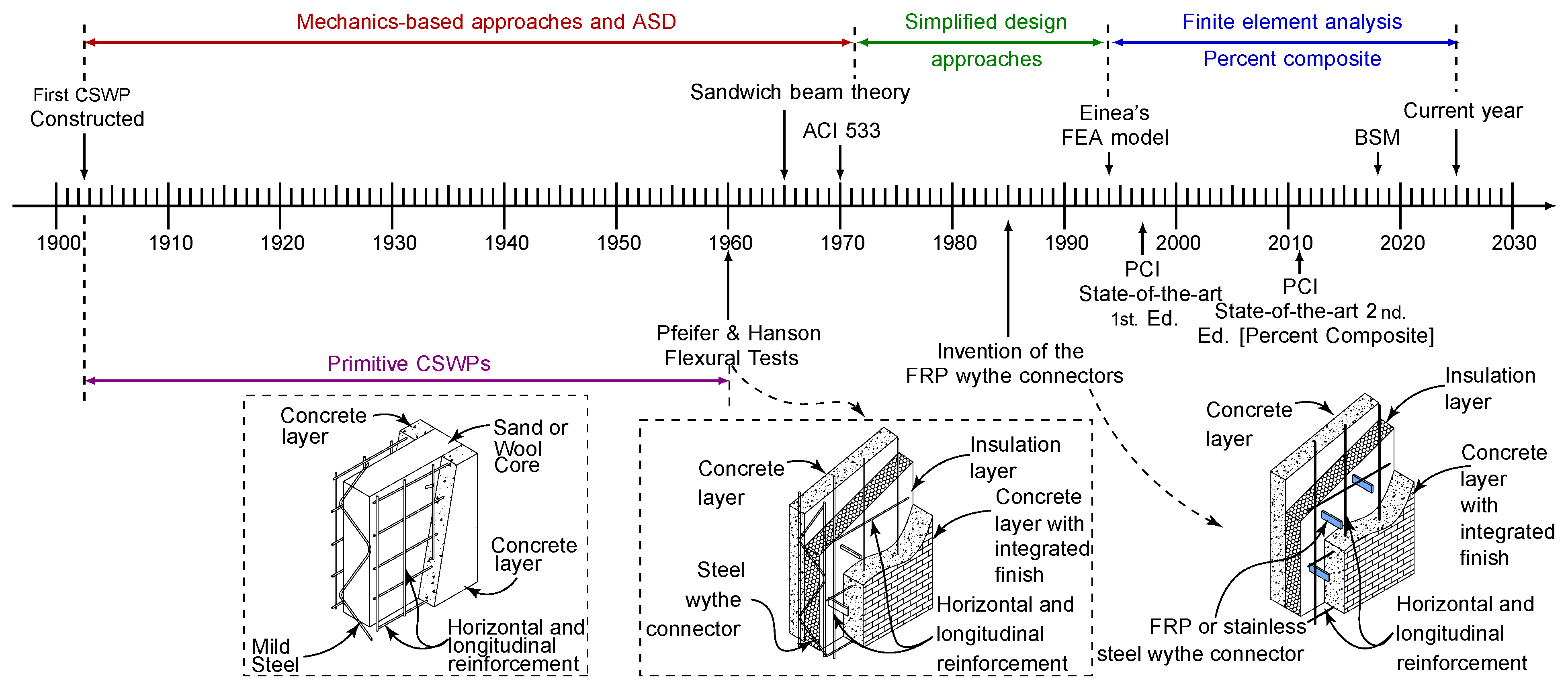
Figure 1. Timeline of the evolution of CSWPs since their invention. Illustration by the authors.
Sustainability 17 03704 g001
Figure 2. Examples of buildings constructed with concrete sandwich wall panels: figures (ac) showcase storage and data center buildings (reproduced with permission from ATMI Precast), figures (df) show recreational, office, and school buildings constructed using tilt-up concrete (reproduced with permission from HK Composites), and figures (gi) show cast-in-place panels used as partition or load-bearing walls, for residences, and for industrial buildings (reproduced with permission from Isotex Dominicana). All rights reserved ©.
Sustainability 17 03704 g002
Figure 3. Testing of CSWP wythe connectors: (a) mechanics of the single-shear test, (b) mechanics of the double-shear test, and (c) corresponding load-versus-displacement results, as described in Ref. [30]. In the illustration, P is the applied load, M is the moment generated due to the eccentricity of the applied load, e is the eccentricity, and y is the vertical distance between the wythe connectors. Illustration by the authors.
Sustainability 17 03704 g003
Figure 4. Finishing types applied to CSWPs: (a) as-cast surface, (b) acid etch, (c) exposed aggregate, and (d) abrasive blast. Photos courtesy of Olympus Precast, all rights reserved ©.
Sustainability 17 03704 g004
Figure 5. Electric circuit analogy for determination of thermal resistance using: (a) parallel-path method, (b) isothermal-planes method, (c) zone/modified zone method, and (d) characteristic section method. Gray represents concrete, pink represents insulation, and blue represents an alternate bridging material (e.g., connector, filler, etc.). Illustration by the authors.
Sustainability 17 03704 g005
Figure 7. Illustration of the mechanics of a CSWP under out-of-plane (a), axial (b), and thermal (c) loads. In panel (a), the out-of-plane load deforms the panel, generating relative displacement of the wythes (slip); in (b), the axial load (P) applied on the loaded wythe ( t 1 ), with its eccentricity with respect to the centroid of the section, bends the panel, generating a relative displacement of the wythes; and in (c), a rise in the temperature of one wythe generates thermal expansion, which is prevented by the wythe connectors and in turn causes panel bowing. Illustration by the authors.
Sustainability 17 03704 g007
Figure 8. Illustration of the behavior of CSWPs under combined flexure and compression observed by Al-Rubaye [90]. Illustration by the authors.
Sustainability 17 03704 g008
Figure 10. Illustration of the elastic percent composite variation versus the stiffness of the connecting medium for the 75-75-75 panel shown in Ref. [9]: (a) Composite action I P C versus average shear stiffness, (b) composite action S P C versus average shear stiffness. Reprinted from Ref. [9] with permission from the American Concrete Institute (ACI) Copyright 2020.
Sustainability 17 03704 g010
Figure 11. Details of CSWP connector layouts: uniform layout (a), linearly variable layout (b), and end-heavy layout (c). Illustration by the authors.
Sustainability 17 03704 g011
Figure 12. Typical thermally efficient and inefficient details used in the construction of CSWPs [32,62,74]. (ac) show beam-to-panel, slab-to-panel, and joist-to-panel connections; (df) illustrate corner panel-to-panel connections; and (gi) present side-by-side panel-to-panel connections.
Sustainability 17 03704 g012
Figure 13. Precast CSWP construction process: plant precast (a), lifting in the yard (b), and erecting the panel at the job site (c). Reproduced with permission from ATMI Precast. All Rights Reserved ©.
Sustainability 17 03704 g013
Figure 14. Tilt-up CSWP construction process: workers placing insulation with wythe connectors at the job site (a), concrete cast on second wythe (b), and erecting the panel in place (c). Reproduced with permission from ICONXUSA L.L.C. All Rights Reserved ©.
Sustainability 17 03704 g014
Figure 15. Shotcrete CSWP construction process: panel preparation prior to concrete placement (a), panel state after one pass of shotcrete (b), and finished surface (c). Reproduced with permission from Isotex Dominicana, all rights reserved ©.
Sustainability 17 03704 g015
Table 1. Different insulation types used in CSWP construction, along with their R-value and symbol representing their cost relative to the baseline insulation (EPS).
Insulation
Type
R-Value per 1 in
(ft2 · F·h/BTU)
R-Value per 25 mm
(m2 · K/W)
Relative
Cost
EPS4.223.8Baseline (X)
XPS5.028.42X
Polyiso6.034.13X
Table 2. Different connector brands, material, and type of composite action achieved by different connector types.
MaterialShapeComposite Action LevelProprietaryTypeKnown Brands
CFRP, GFRP, BFRPGRIDPartialYesContinuousC-GRID
CFRP, GFRP, BFRPRound BarPartialNoDiscreteN/A
GFRPContinuous Bent BarPartialYesContinuousNU Tie
GFRPPinNon-Composite *NoDiscreteHK ST, Sigma DG, Thermomass MC
GFRPRectangular BarPartialNoDiscreteThermomass CC
GFRPUnique GeometryPartialYesDiscreteDelta Tie
GFRPX-PinPartialNoDiscreteSigma DG
GFRP and CFRPUnique GeometryPartialYesDiscreteIconX USA
Reinforced ConcreteSolid ZoneNear FullNoDiscrete/ContinuousN/A
Stainless Steel3D PanelPartialNoContinuousTIPS
SteelPerforated PlatePartialNoDiscreteN/A
SteelPipePartialNoDiscreteN/A
SteelRound BarPartial/Near FullNoDiscreteN/A
SteelTrussPartial/Near FullNoContinuousMeadow Burke, MetRock
ThermoplasticUnique GeometryPartialYesDiscreteHK CA
† There is no specific brand for a perforated plate, round pipe, or steel bar used as a wythe connector. * Non-composite connectors provide a small amount of composite action that is neglected during design.
Table 3. Variation of the R-value for winter and summer as a function of the insulation thickness for a CSWP with 75 mm thick wythes and different insulation thicknesses. Adapted from Luebke et al. [27].
Insulation
Thickness (mm)
Total Panel
Thickness (mm)
R winter R summer
(m2 ·K/W)(m2 ·K/W)
Solid Panel1500.230.24
502002.192.2
1002504.144.16
1503006.16.11
2003508.068.07
25040010.0110.03
Table 4. Summary of methods that can be used for the linear and non-linear design of CSWPs.
MethodType of SolutionType of ModelUse in Industry/SoftwareReferences
AllenClosed-FormLinearNo evidence[110]
BSMNumericalNon-LinearLECWALL, ERIKSSON WALL[20,44,87,116,117]
HamedClosed-FormNon-LinearNo evidence[88]
Holmberg and PlemClosed-FormLinearNo evidence[13]
ISBTIterativeLinearLECWALL[111]
MBMIterativeLinearIn spreadsheet form[112]
Percent CompositeClosed-FormNon-LinearIn spreadsheet form[19]
Shear FlowClosed-FormLinearIn spreadsheet form[19]
SLDAMIterativeNon-LinearNo evidence[115]
SMPCIPIterativeNon-LinearNo evidence[87]
SSBTIterativeLinearIconX USA [until 2023][48]
Timoshenko–EhrenfestClosed-FormLinearNo evidence[113]
TomlinsonIterativeNon-LinearNo evidence[45]
Disclaimer/Publisher’s Note: The statements, opinions and data contained in all publications are solely those of the individual author(s) and contributor(s) and not of MDPI and/or the editor(s). MDPI and/or the editor(s) disclaim responsibility for any injury to people or property resulting from any ideas, methods, instructions or products referred to in the content.