Abstract
Grid-connected photovoltaic (PV) systems require a power converter to extract maximum power and deliver high-quality electricity to the grid. Traditional control methods, such as proportional-integral (PI) control for DC-link voltage regulation, often struggle under abnormal operating conditions, resulting in voltage fluctuations and instability in the maximum power point tracker (MPPT). This paper proposes a synergistic control strategy that combines a musical chairs algorithm (MCA) MPPT with sliding mode control (SMC) together for the boost converter DC-link control. This approach enhances DC-link voltage stability by switching the MPPT to SMC of the boost converter when the DC-link voltage exceeds the predefined limit. This strategy enhances the stability of the DC-link voltage and allows for a smaller DC-link capacitor, thereby reducing system cost and improving the power quality of PV systems. A phase-locked loop (PLL) further ensures effective grid synchronization. The reduction in DC-link voltage overshoot (from 570 V to 522 V) improved stability under varying irradiance conditions. Moreover, a 48 V reduction in overshoot voltage and a 66% decrease in DC-link voltage ripple (standard deviation from 17.93 V to 5.92 V) occurred. Simulation and experimental results demonstrate the superiority of the proposed strategy compared to the case without coordination between the DC-DC converter and inverter controllers, particularly under challenging conditions.
1. Introduction
The increase in energy demand and the scarcity of fossil fuels force the world to increase its use of renewable energy sources such as wind and solar energies [1]. There are many challenges in interconnecting photovoltaic (PV) energy sources with electric utility. One of these challenges is the power quality of the generated power from PV systems during normal and abnormal operating conditions. The PV arrays should be controlled via a DC-DC converter to track the maximum power point (MPP) during all operating conditions using maximum power point trackers (MPPT) algorithms. Due to the multiple peaks generated in the power-voltage characteristics of the PV array with partial shading conditions (PSCs) modern MPPT algorithms based on metaheuristics have been intensively used, such as particle swarm optimization (PSO) [2], grey wolf optimization (GWO) [3], and musical chairs algorithm (MCA) [4]. The metaheuristic algorithms outperform the conventional MPPT algorithms, such as hill climbing [5] and perturb and observe (P&O) [6], in tracking the MPP in PSCs. The main problem of the metaheuristic algorithms in the use of MPPT of PV systems is its long convergence time. This limitation has been avoided through a gradual reduction in the search agents, which has been introduced in the MCA [4] and modified PSO [2].
The DC-link capacitor functions as an energy reservoir, smoothing out voltage fluctuations. It absorbs excess energy during surges and releases it during dips, stabilizing the DC-link voltage. This ensures a reliable and consistent power supply to the inverter. While larger capacitors offer superior ripple reduction, they also introduce conduction losses due to their inherent equivalent series resistance (ESR). Moreover, using large capacitors increases the PV system cost and forces the designers to use electrolyte capacitors instead of thin film ones which have a short lifetime [7]. Designers must carefully select an optimal capacitor value, balancing system requirements, load profiles, budget constraints, voltage ripple limits, system size, and inverter switching frequency. Various approaches have been proposed to determine the optimal capacitor size for DC-link voltage regulation [8,9]. Moreover, several studies have been introduced to enhance the stability of the DC-link voltage through the use of modern control techniques for the three-phase PWM inverters [10,11,12,13,14]. The instability problem of the DC-link voltage of the PV system contributes to the distortion of the output power, which is overlooked in most of the MPPT studies [15,16]. Many other techniques have been used to enhance the stability of the DC-link voltage such as the sliding mode control (SMC) strategy [17,18,19], proportional-integral (PI) controllers [20,21], fuzzy logic controller (FLC) [22,23], sigma-delta modulation control [24], observer-based backstepping technique [25], and neural network-integrated with an adaptive backstepping framework [26]. A detailed comparison between the use of the direct sliding mode controller DSMC and PI controller used to regulate the DC-link voltage is introduced in [7]. Hybrid control techniques between two of these controllers have been used to improve their performances, such as the use of the SMC and FLC [21], and the use of SMC with the proportional-integral differentiator (PID) controllers [27]. Backstepping-based super-twisting SMC MPPT control with differential flatness-oriented observer design for PV systems [28,29]. Another study used SMC of the bidirectional converter connected to a battery storage system with a stand-alone PV system to enhance the stability of the DC-link [11].
The application of PI and PID controllers to DC-link voltage control can lead to suboptimal performance characterized by steady-state oscillations and transient overshoot [12]. Seo and Choi [30] pioneered the application of fractional-order PID control to boost converters, leveraging input inductance and output capacitance to match the closed-loop transfer function to a first-order system. Their findings demonstrated superior performance compared to traditional integer-order PID controllers. Subsequent research explored adaptive control [31] and quantitative feedback theory [32] to address the challenges of boost converter voltage regulation, further enhancing stability and robustness. Van et al. [33] introduced a phase-shift full-bridge topology with PI control, achieving improved performance over conventional DC-DC converters.
To derive a control parameter, linearization around a specific operating point is necessary. This limitation restricts the boost converter’s operational range. To address this, nonlinear controllers, often employing intelligent control techniques, have been proposed [21,26]. Nizami and Chakravarty [26] presented a neural network-based adaptive backstepping approach for output voltage control in a boost converter. Their results demonstrated rapid parameter estimation and satisfactory output voltage tracking performance.
A comprehensive comparison of SMC-FLC and traditional PID controllers for boost converter applications is presented in [21]. The SMC-FLC approach effectively leverages the strengths of FLC and SMC, offering superior transient response and robustness. The study underscores the SMC-FLC’s ability to outperform PID controllers, particularly in terms of response time and stability under dynamic operating conditions [21].
Reference [34] introduced a novel observer-based backstepping sliding mode control (OBSMC) strategy for regulating the output voltage of a boost converter in DC microgrids. The OBSMC addressed the challenges posed by fluctuations in temperature and solar irradiance, which can impact the converter’s output voltage. By employing an observer to estimate system states without requiring additional sensors, the OBSMC effectively combined backstepping and SMC techniques to ensure robust voltage regulation under varying conditions and load changes [34]. The main shortcoming of this control strategy is the lack of coordination between the control of the boost converter and the PWM inverter to enhance the stability of the DC-link voltage, which has been avoided in the control strategy used in this paper.
1.1. Sliding Mode Control
SMC is a robust control technique that uses switching between different control laws to ensure system stability and performance despite uncertainties and disturbances. It forces the system’s state variables to follow a predefined sliding surface, achieving desired performance even in nonlinear systems. While offering advantages like robustness, simplicity, and fast response, SMC can also have drawbacks such as high-frequency switching, potential instability, and parameter-tuning challenges. The study shown in [7] proposed a novel DSMC to enhance the performance and reliability of standalone PV systems. By replacing bulky electrolytic capacitors with smaller film capacitors, the DSMC effectively regulated DC-link voltage while improving system dynamics. The controller’s ability to maintain stable system operation under varying load conditions, including rapid load changes, was demonstrated through hardware-in-the-loop experiments and simulations. The system’s mode alternation strategy and MPPT capability further contributed to its overall robustness and efficiency [7].
The study shown in [13] highlighted the importance of DC-link capacitance in ensuring the stable operation of three-phase PV inverters. While traditional electrolytic capacitors are commonly used, the study explored the potential benefits of using film capacitors, despite their higher cost. By analyzing the control dynamics of PV inverters and identifying a right-half-plane pole, the paper developed design rules to minimize required DC-link capacitance while maintaining system stability [13]. The study introduced in [35] proposed a model-based MPPT technique for two-stage grid-connected PV systems. By integrating constant power generation (CPG) and an adaptive DC-link controller, the system enhances power regulation and transient behavior. A finite-set model predictive control algorithm optimizes active and reactive power exchange with the grid while minimizing switching losses. The proposed approach effectively addresses the challenges of irradiance and temperature variations while improving overall system performance [35]. The study introduced in [36] proposed a SMC to maximize power output from a PV array under changing conditions. The SMC tracks the ideal voltage for maximum power from the PV panel, relying on a previously developed design and using a P&O MPPT algorithm to determine the reference voltage. The system includes the PV panel, a boost converter, and a DC load. The SMC is designed to be insensitive to variations in the system and precisely follows the reference voltage provided by the MPPT algorithm. Compared to a traditional PID controller, the SMC performs better. The study adjusts the error signal obtained from MPPT using the SMC to ensure the effectiveness of the MPPT without controlling the DC-link voltage [36]. Similar studies used the SMC as an MPPT of the PV systems [37]. The study [38] discussed the design of SMC for PV systems to enhance MPPT efficiency. It highlighted the difficulties in predicting the optimal voltage and current due to the nonlinear behavior of PV arrays affected by environmental conditions. The study reviewed existing MPPT solutions like incremental conductance (IC) and P&O, emphasizing their implementation simplicity and tracking efficiency. The proposed SMC design accounts for all elements required for stable PV system operation, including MPPT algorithm requirements and environmental perturbations. The proposed design is compared with existing solutions, highlighting its ability to ensure stable sliding regime, appropriate settling time, and overshoot for the PV voltage required by MPPT algorithms. This study aims to provide a comprehensive solution for efficient power tracking in PV systems by addressing the limitations of previous approaches. It compares the performance of SMC based on different settling times, showcasing graphs for overshoot and energy losses [38]. The study introduced in [37] presented a new solution for MPPT in PV systems using SMC. The paper highlighted the benefits of using SMC over traditional linear controllers, particularly in handling oscillations and ensuring system stability across the PV panel’s operation range. A SMC-based PV voltage control surface is proposed to track voltage references and mitigate bulk voltage oscillations without relying on linearized models. The effectiveness of the proposed solution is validated through simulations, demonstrating its superior performance in tracking the voltage reference and mitigating perturbations compared to existing methods. Another interesting strategy [14] regulated the overvoltage problem in the DC-link of grid-connected PV systems in the event of faults. It proposes a novel control scheme for boost converters to improve the low-voltage ride-through (LVRT) capability without additional hardware costs. In another study [14], a control strategy that detects the DC-link voltage during normal operation disables the MPPT controller when the threshold is exceeded, and employs a PI controller to keep the DC-link voltage within the specified limit was introduced. The proposed control scheme has a positive effect on the transient stability of power systems and prevents shutdowns during faults [14]. The IC MPPT used in this study may not effectively track the MPP under PSCs, leading to significant power losses in the PV system. This problem is solved in the proposed study by using the MCA optimization algorithm [4]. In addition, the PI controller used in the DC-link controller suffers from the common drawbacks of PI controllers, such as limited operating range, severe overshoot, and slow response to rapid changes in operating conditions. This problem is very important in such a study as it may occur frequently when the DC-link voltage becomes higher than the reference voltage due to the frequent use of the PI controller. A similar strategy introduced the LVRT capability used with hybrid PV and wind energy systems [39]. A control strategy is proposed to improve the stability of the DC-link voltage by modifying the hybrid system’s control during grid faults. During grid faults, the system is adjusted to protect equipment and maintain power delivery in the proposed system [39]. During grid faults, the MPPT technique of the boost converter is disabled. Concurrently, the voltage source inverter (VSI) is utilized to inject reactive power, enhancing the LVRT capability of the PV station [39].
The study introduced in [40] proposed a sensorless DC-link voltage control for a grid-connected PV system, enhancing system stability and dynamic response under variable irradiance conditions. The proposed scheme reduced the cost and size of the PV system by eliminating the need for a high-voltage sensor. The study focused on the modeling, control, and testing of grid-connected PV micro-inverters. However, it only discussed the effect of solar irradiance variation on DC-link stability and did not address the performance of the MPPT and whole control system with phase shift controllers [40,41].
A detailed comparison between the PV system integration control strategies discussed above is shown in Table 1. This table shows that there is no strategy introduced having coordination between the DC-DC converter and VSI in controlling the DC-link voltage while maintaining the MPP tracking in uniform and PSCs. This table compares ten control strategies in the literature for PV systems with the proposed control strategy, focusing on key components and techniques such as MPPT, DC-link control, BESS integration, inverter control, and overall coordination [36,38]. The results illustrate how different strategies prioritize control objectives in both on-grid and off-grid scenarios. Most on-grid studies (e.g., [39,40], and proposed strategy) employ advanced controllers like SMC or PI controllers to maintain operational efficiency and stability under variable solar irradiance conditions. In off-grid scenarios (e.g., [12,36]), the control strategies prioritize standalone operations reflecting their autonomy from external synchronization constraints. All strategies used are conventional P&O [7,35], IC [39], and SMC [36,38]. While the ten strategies rely on conventional MPPT techniques that are less effective under PSCs, the proposed strategy’s use of the MCA offers a significant advantage. MCA is capable of efficiently locating the global MPP, even in complex shading scenarios, thereby maximizing energy harvesting.

Table 1.
A comparison between different control strategies of PV systems.
Many strategies used SMC in DC-link control [12,38], and the proposed strategy due to its ability to maintain stability and efficiency in both on-grid and off-grid systems. Some other strategies used PI controllers such as [39,40], and PI controllers are preferred for their simplicity and ease of integration in grid-connected systems. However, they may lack the robustness needed for systems exposed to high uncertainties. The only study used constant power generation (CPG) [35] which switches the MPPT control to the CPG when the DC-link voltage becomes greater than the predefined value for the purpose of coordination.
Three strategies [7,37] used the BESS for extra-coordination to enhance the stability and reliability of the DC link voltage. Due to the high cost and other complications of the BESS that can be avoided, especially with the on-grid system, most of the studies did not prefer to use it and, for this reason, it has not been included in the proposed system.
Many studies did not concentrate on the inverter control techniques and concentrated only on the boost converter, such as [12,36]. The other strategies showed in detail how the inverter control participates in controlling the DC-link voltage by controlling the output active and reactive powers to the grid [38,39,40], and the proposed strategy.
It is clear from Table 1 that the systems with coordination between the DC-DC converter and the inverter control are [35,37] to optimize interactions between the inverter, MPPT, and other controllers to enhance the overall efficiency and stability of DC-link voltage. This shows great merit for these strategies but the main problem is their use of conventional MPPT strategies or conventional control strategies for the DC-link voltage such as PI or CPG control strategies. These limitations have been avoided in the proposed strategy by using the MCA to effectively track the MPP during the PSCs and the SMC to effectively and swiftly control the DC-link voltage.
Based on the comparison study introduced in Table 1, the proposed strategy offers a compelling solution by combining advanced MPPT using MCA and robust DC-link control using SMC. This integrated approach enables efficient power extraction, stable operation, and enhanced system performance, particularly in dynamic and uncertain environments.
1.2. Key Contributions of the Paper
This paper presents a novel control strategy for three-phase grid-connected PV systems. Combining the MCA for MPPT with SMC in the boost converter can enhance the coordination with the VSI, the proposed strategy offers several contributions:
- Enhanced DC-link voltage stability under varying solar irradiance, improving overall system reliability.
- Improved power quality using a synergistic control approach leads to better power quality by reducing voltage fluctuations and harmonics.
- Reduced system cost and size by enhancing DC-link voltage stability.
- Increasing the resiliency of the system against disturbances and uncertainties by the coordination of the boost converter and VSI controllers.
These contributions highlight the innovative and practical nature of the proposed control strategy for three-phase grid-connected PV systems.
1.3. Study Outlines
Section 1 of this paper provides a comprehensive literature review, highlighting the limitations of conventional control techniques in addressing power quality and stability issues. Section 2 introduces a detailed description of the proposed system, presented in Section 2, which comprises a PV array, a DC-DC boost converter, a DC-link capacitor, and a VSI. The control strategy, presented in Section 3, employs the MCA for efficient MPPT and SMC for robust DC-link voltage regulation. Moreover, the mathematical models developed to accurately represent the dynamics of the system components are introduced in Section 3. Rigorous simulations under diverse solar irradiance conditions, as presented in Section 4, demonstrate the superior performance of the proposed strategy in terms of DC-link voltage stability, power quality, and overall system reliability compared to conventional approaches. The concluding section summarizes the key findings and outlines potential avenues for future research, including the integration of energy storage systems and the exploration of advanced control techniques shown in Section 5.
2. System Description
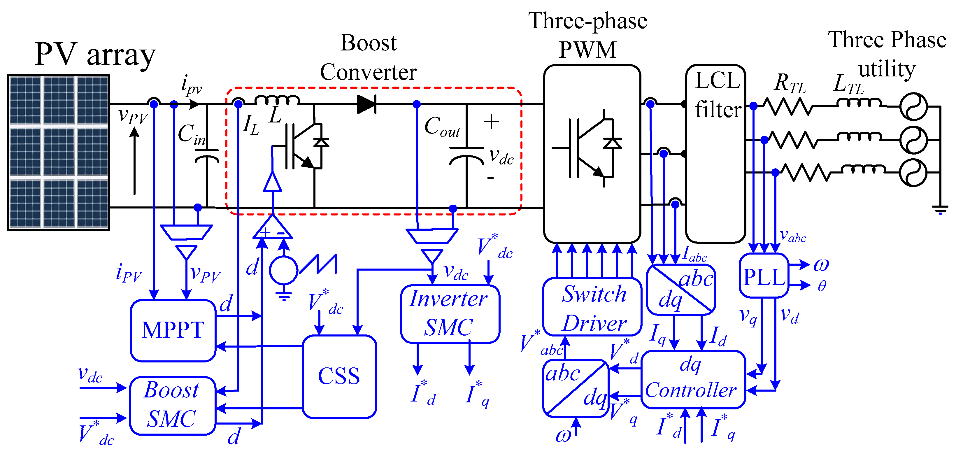
A typical PV system comprises a PV array, a DC-DC boost converter, a DC-link capacitor, and a three-phase VSI as shown in Figure 1. The boost converter is crucial for maximizing power extraction from the PV array by operating it at its MPP. This is typically achieved using optimization algorithms, such as the MCA. However, while MCA excels at MPP tracking, it lacks direct control over the DC-link voltage. Traditionally, the DC-link voltage is regulated solely by the inverter’s control system, often employing SMC [7,10]. This approach works well under normal operating conditions. However, during disturbances or abnormal conditions, the system may struggle to maintain DC-link voltage stability. This can lead to excessive voltage levels, potentially damaging the DC-link capacitor, or the injection of low-frequency harmonics into the grid, degrading power quality. To address this limitation, this paper proposes a novel control strategy that shares the responsibility of DC-link voltage control between the boost converter and the VSI. This synergistic approach enhances the system’s robustness and performance.
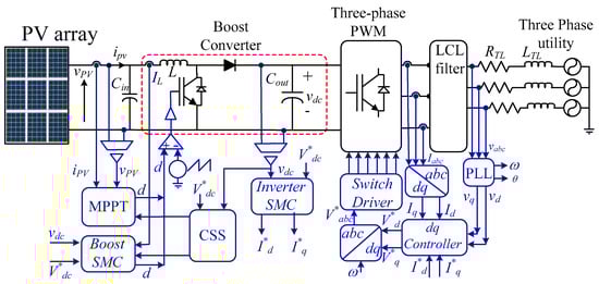
Figure 1.
Power and control circuits of the proposed control strategy.
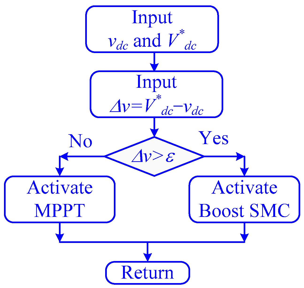
The proposed strategy uses the MCA controls of the boost converter to track the MPP and leave the control of the DC-link on the VSI controller exclusively. Meanwhile, during abnormal operation, the DC-link voltage exceeds a predefined threshold, and the control of the DC-DC controller is transferred to SMC to rapidly stabilize the DC-link voltage synergistically with the VSI controller. Once the voltage is returned to lower than this limit, the control is returned to the MCA for MPPT. This strategy is called the control selection strategy (CSS);the logic is shown in Figure 2.
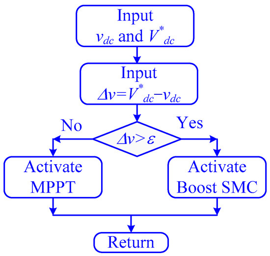
Figure 2.
The schematic of the control selected strategy.
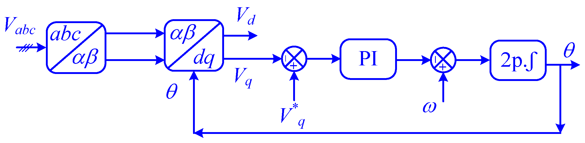
By effectively coordinating the control actions of both the boost converter and the VSI, this strategy ensures stable DC-link voltage, minimizes power quality issues, and reduces the required size of the DC-link capacitor, leading to a more cost-effective and efficient PV system. The VSI employs a phase-locked loop (PLL) to synchronize with the grid voltage and an SMC d-q controller to regulate active and reactive power flow, as shown in Figure 3 [39].
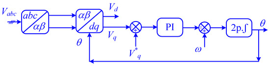
Figure 3.
Block diagram of the PLL controller.
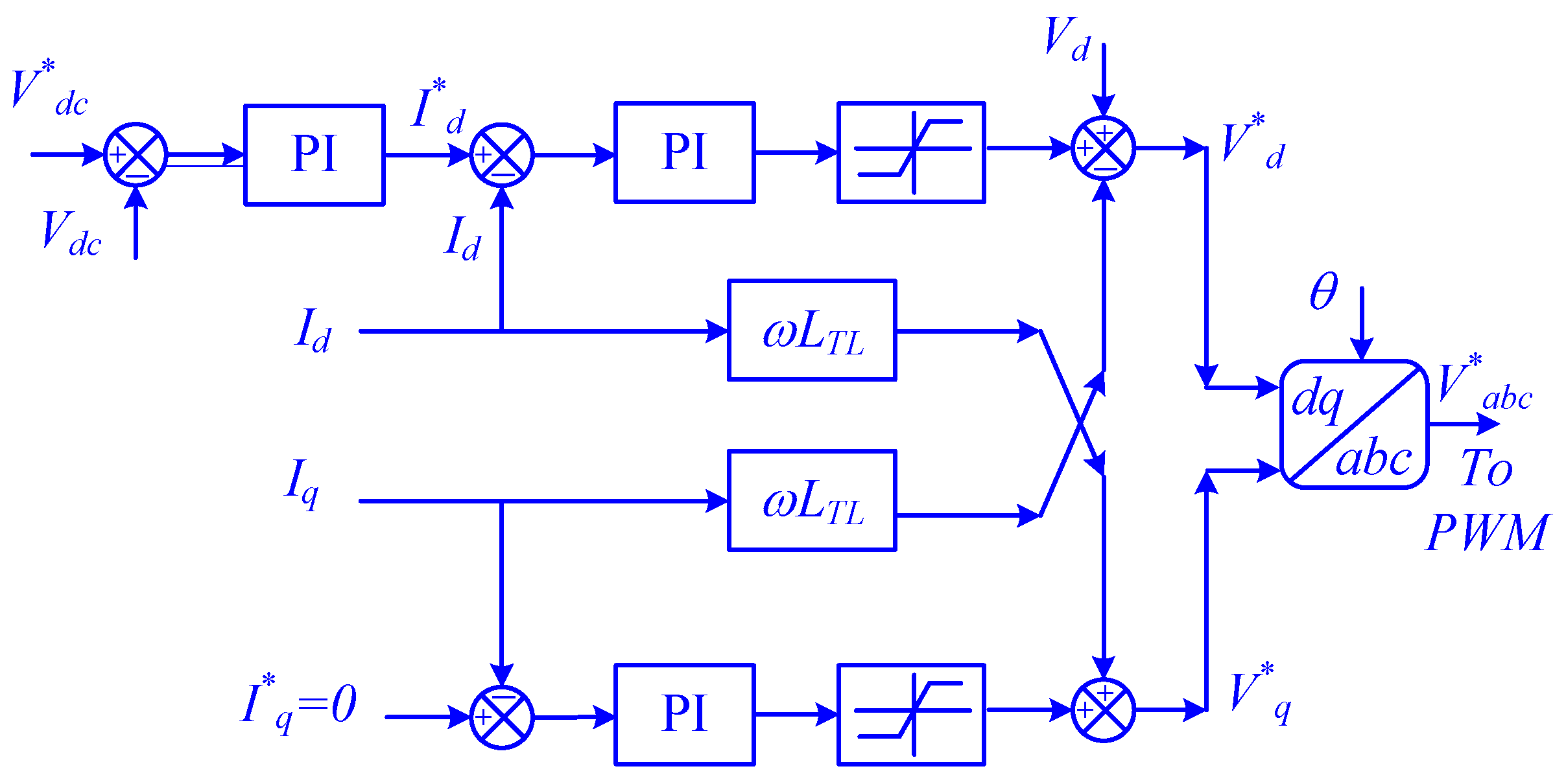
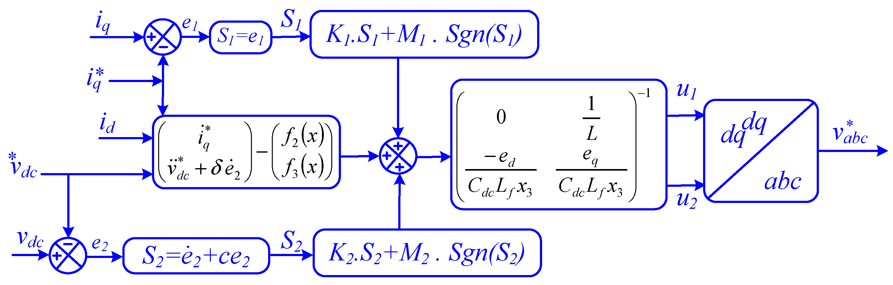
The d-q controller of the VSI also contributes to DC-link voltage regulation by adjusting the power injection into the grid. The d-q controller controls the d-q components to inject more power during high DC-link voltage and vice versa, as shown in Figure 4. The proposed control strategy offers a significant improvement in the performance and reliability of PV systems. By sharing the responsibility of the DC-link voltage regulation, the system becomes more resilient to disturbances and can operate more efficiently.

Figure 4.
The schematic diagram of the d-q controller.
3. System Modeling
3.1. Mathematical Model of the Boost Converter
The mathematical model showing the dynamics of the boost converter is detailed in the following subsection based on the studies shown in [42,43,44]. The state space equations of the boost converter are listed in the following equations:
where vPV and iPV are the PV terminal voltage and current, iL is the inductor current, vdc is the DC-link voltage, idco is the output current from the DC-link capacitor, and u is the switching state of the boost converter. All these symbols are also defined in the list of symbols table.
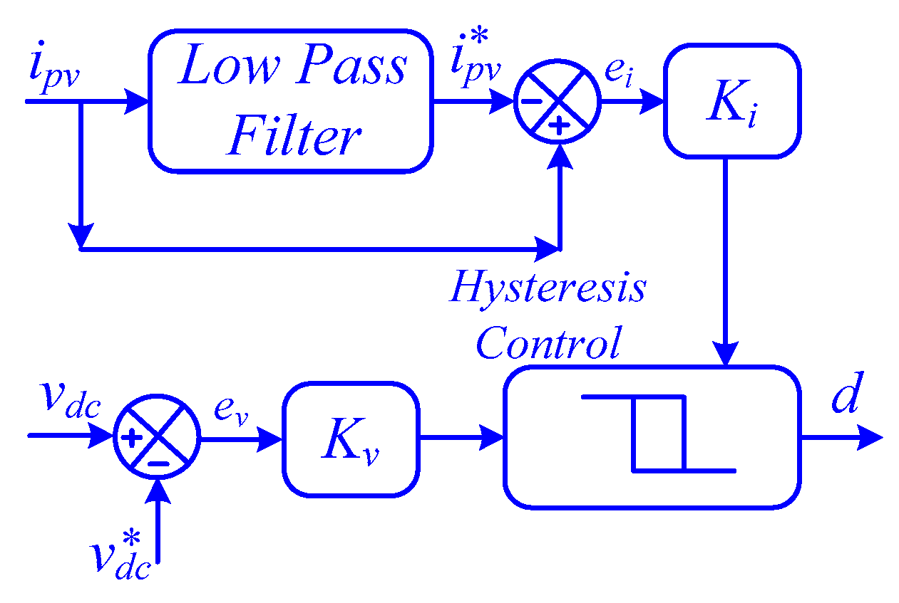
Selecting the appropriate state variables for the SMC of a boost converter is crucial. Typically, these variables are determined by the desired control strategy. To control the DC-link voltage, the inductor current and DC-link voltage deviations are chosen as state variables. However, the fluctuating inductor current made it difficult to set a suitable reference value. To address this, the fundamental component of the inductor current using a low-pass filter is extracted, as shown in Figure 5 [45]. This modification significantly enhanced the dynamic stability of the SMC, particularly during abnormal operating conditions. By incorporating the filtered current reference as a state variable, as shown in the following equation, the time derivative from Equation (6) can be obtained [45].
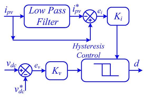
Figure 5.
Sliding mode control of boost converter.
Let , , and [45], the state space equations of the boost converter can be reformulated, as shown in (4) to (6).
The three state equations shown above can be rewritten in the matrix form as shown in the following equation:
where , .
The sliding surface σ of the proposed SMC can be obtained from (8), as follows:
where u is the switching state, which can be obtained from Equation (9), .
To ensure the system is stable and sliding well through the sliding surface, the Lyapunov stability criteria should be applied as shown in the following equation [45]:
where η is a large positive number.
Based on the stability analysis shown in [45], the value of g should be between the values shown in (12). Similarly, the time constant of the low-pass filter can be obtained from Equation (13) [45].
where Dmin and Dmax are the minimum and maximum allowable duty ratio of the boost converter.
3.2. Mathematical Model of the Three-Phase VSI
The state space equation at the output of the three-phase VSI is shown in the following equation [46]:
where VI is the vector of the inverter output voltage as shown in (15), I is the inverter output current which can be obtained from (16), E is the vector of electric utility vector which can be obtained from (17)
where va, vb, vc are the inverter output voltages, ia, ib, ic are the three-phase output currents, ea, eb, ec are the grid three-phase voltages.
By using park transformation, the three-phase rotating frame can be transferred to d-q reference frame with phase angle θ = ωL, which can be obtained from the PLL as shown in the following equation:
where ed and eq are the park’s transformations of the grid voltages, vd and vq are the park’s transformations of the voltages at the output of the three-phase inverter, and id and iq are the park’s transformations of the grid voltages.
By neglecting the switching losses of the three-phase VSI, the output power from the DC-link capacitor is equal to the three-phase power at the output terminal from the inverter, as shown in (19).
The voltage variation in the DC-link capacitor in function of its input and output currents can be determined from (20).
Substituting the value of idco from Equation (19) into (20), the voltage variation equation of the DC-link can be obtained as shown in (21).
The state space model of the inverter can be obtained from (18) and (21) can be written as shown in (22) [46].
where , , and , .
The proposed SMC is designed to effectively control the DC-link voltage (x3 = vdc) and the reactive power to the grid using the variable x2 = iq. The two variables are considered in the proposed SMC and for this reason, the output variables are y = (y1, y2) = (x1, x3)T = (iq, vdc)T. Based on this the error signals are defined as the following [46]:
Based on the error signals shown above the sliding surface can be chosen as shown in the following:
Substituting (25) into (22) the relation between the input and output of SMC is shown in the following equation [46]:
Based on the values obtained from the above equation the SMC can be proposed as the following:
The detailed description of the SMC used with the three-phase PWM inverter is shown in Figure 6 [46].

Figure 6.
Sliding mode control of three-phase inverter [46].
4. Simulation Work
4.1. System Parameters
The simulation work introduced in this study is implemented in Matlab/Simulink. Matlab/Simulink was chosen for its robust toolboxes for power electronics and control systems, its widespread acceptance in academia and industry, and its ability to accurately model complex systems like PV inverters. This is now clarified in the text. The boost converter parameters are selected based on the design strategy introduced in [10,47]. The PV modules used in this study version 2024 are Canadian solar CS5P-220M, Canadian solar, Guelph, ON, Canada [48] with electrical data shown in Table 2. The I-V and P-V characteristics in different solar irradiances and 25 °C of the PV module are shown in Figure 7. The proposed system is 100 kW in size, so 92 parallel strings, each one containing five series modules that are used to construct the PV array of the proposed system. The PV system is connected to the grid through a transmission line, with values shown in Table 3.
Table 2.
The electrical characteristics of PV module.
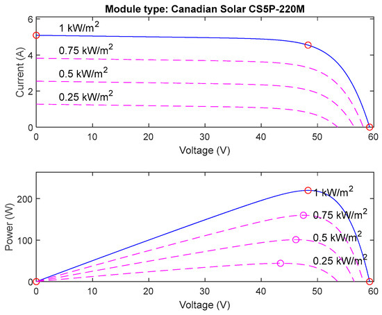
Figure 7.
The I-V and P-V characteristics in different solar irradiances and 25 °C of the PV module.
Table 3.
The parameters of the proposed system.
System ratings (100 kW), temperature effects (±5% efficiency loss at 50 °C), and load-dependent efficiency (94–97%).
Two different studies are introduced in this simulation work. The first one is to study the effect of sudden and gradual changes in solar irradiance on the performance of PV systems without CSS. The second study is performed to examine the performance of the PV system when the CSS is used. These two studies are illustrated in the following subsections.
4.2. Simulation Results
- i.
- Without DC-Link Coordination (Without CSS)
To evaluate the effectiveness of the proposed control strategy, a comprehensive simulation study was conducted. Various solar irradiance profiles were applied to the system: constant, gradual change, and sudden change.
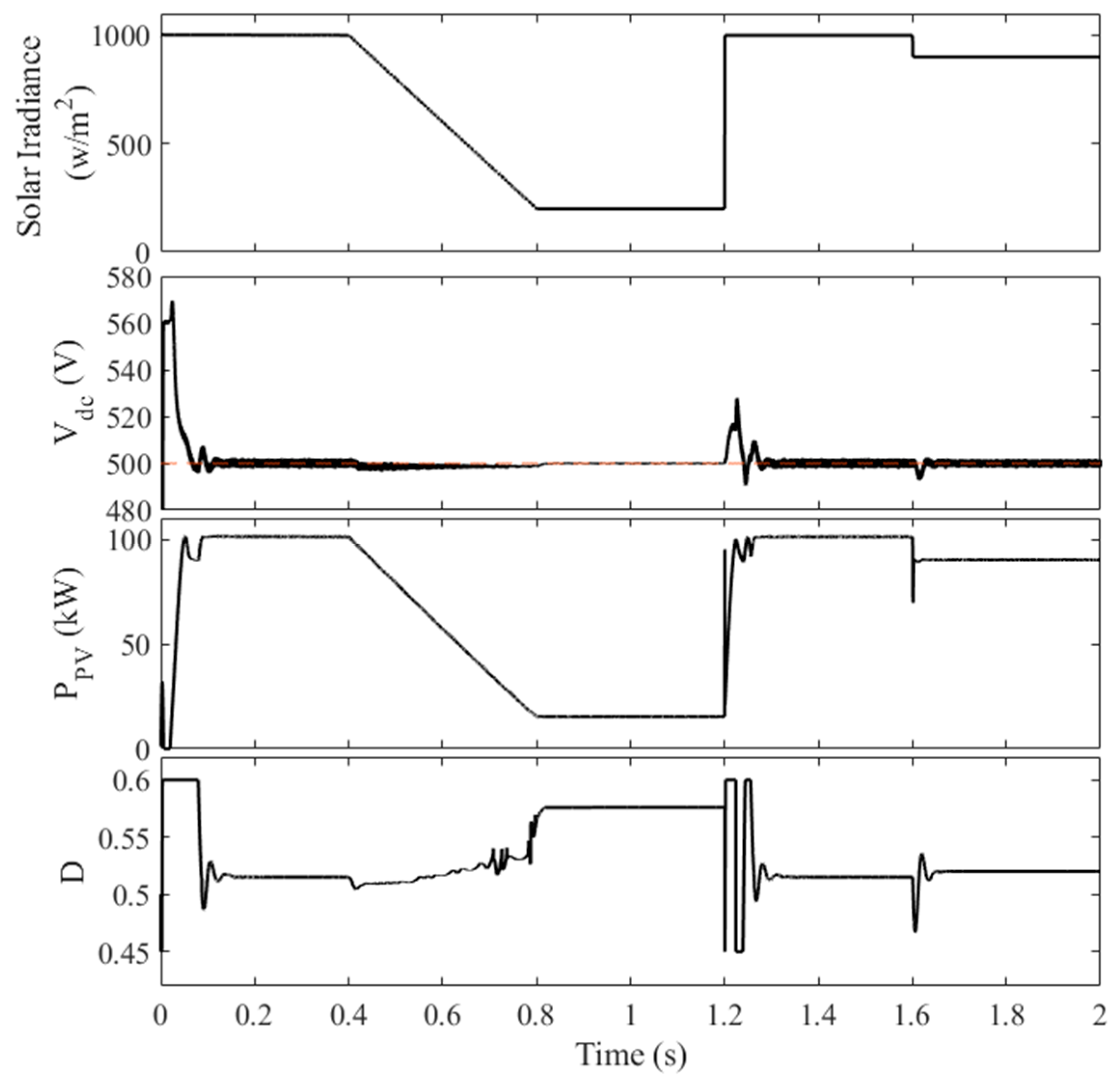
Figure 8 illustrates the system’s performance when the MPPT algorithm (MCA) is used without DC-link voltage coordination. The simulation was carried out over 2 s, with the following irradiance profile:

Figure 8.
The performance of the PV system without the CSS.
- 0–0.4 s: Constant irradiance of 1000 W/m2
- 0.4–0.8 s: decrease in irradiance from 1000 W/m2 to 200 W/m2
- 0.8–1.2 s: Constant irradiance of 200 W/m2
- 1.2–1.6 s: Constant irradiance of 1000 W/m2
- 1.6–2.0 s: Constant irradiance of 900 W/m2
The selection of such an irradiance pattern is performed to show high, low, gradual, and sudden changes in solar irradiance on the performance of the PV system. As shown in Figure 8, the system exhibits a significant overshoot in the DC-link voltage (up to 570 V) during the initial 50 ms. This overshoot occurs due to the rapid increase in solar power generation, which the VSI controller struggles to accommodate. The subsequent decrease in irradiance causes a voltage dip, further highlighting the limitations of the traditional approach. The lack of coordination between the MPPT and the VSI controller results in poor DC-link voltage regulation, potentially leading to damage to the DC-link capacitor and increased harmonic distortion in the grid-side voltage and current waveforms. This can be easily concluded from the high DC-link voltage at t = 1.2 s where its value increased to 525 V.
In contrast, the proposed control strategy effectively addresses these issues by sharing the responsibility of DC-link voltage regulation between the two controllers. This ensures a more stable and reliable operation of the PV system, even under dynamic operating conditions.
- ii.
- With DC-Link Coordination (with CSS)
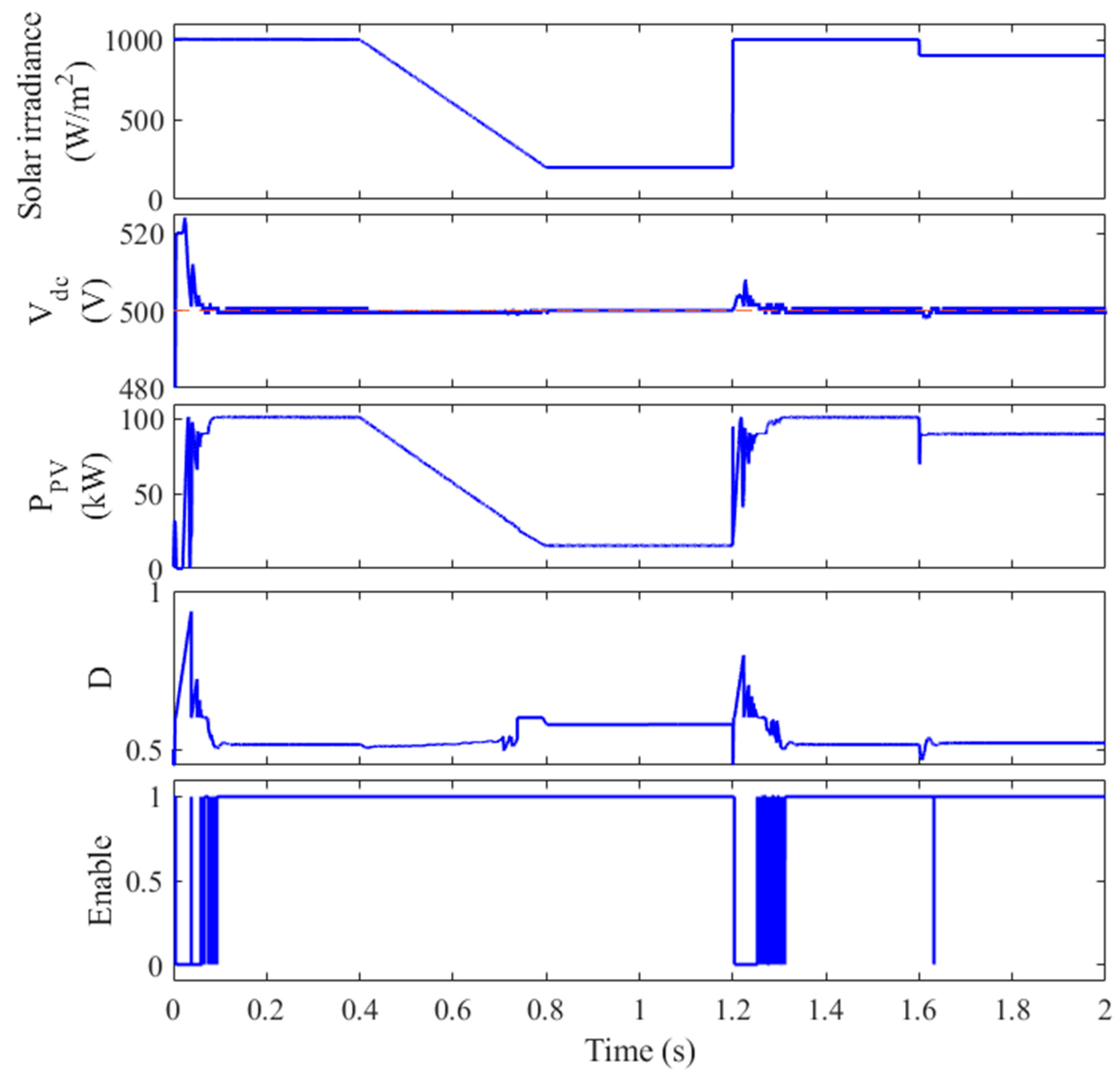
The proposed strategy facilitates seamless coordination between the boost converter controller and the VSI controller to maintain a stable DC-link voltage. The MCA is employed for MPPT until the DC-link voltage reaches a predefined threshold (502 V). Subsequently, control is transferred to the SMC to reduce the power drawn from the PV array, thereby limiting the increase in DC-link voltage to synergistically work with the VSI control to fasten the reduction in the DC-link voltage. In this study, the SMC is activated when the DC-link voltage exceeds 502 V, which corresponds to a 0.4% increase over the reference voltage of 500 V. As illustrated in Figure 9, the peak overshoot voltage is significantly reduced to 522 V, compared to 570 V in the case without SMC. The enable signal for the SMC is activated during the initial transient period, effectively mitigating the initial overshoot. Additionally, when the irradiance abruptly increases at t = 1.2 s, the SMC is triggered to limit the voltage rise to 504.3 V, instead of the 525 V observed in the previous case without CSS. This demonstrates a substantial reduction in transient voltage fluctuations, ensuring a more stable and reliable system operation.
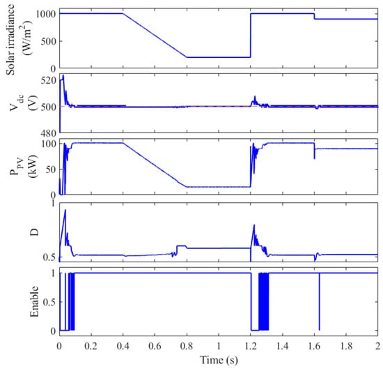
Figure 9.
The performance of the PV system with the CSS.
- iii.
- Comparison between with and without CSS
To further illustrate the benefits of the proposed coordination strategy (CSS), a comparative analysis of the DC-link voltage waveforms for both cases (with and without coordination) is presented in Figure 10. As evident from the figure, the overshoot voltage is significantly reduced from 570 V to 522 V, and the peak voltage at t = 1.2 s is lowered from 525 V to 504.3 V. These results unequivocally demonstrate the superior performance of the coordinated control strategy. Moreover, the DC-link voltage in the coordinated case (CSS) exhibits a significantly lower ripple, with a standard deviation of 5.92 V compared to 17.93 V in the uncoordinated case. This reduction in voltage fluctuations contributes to improved system stability and reduced stress on the DC-link capacitor.
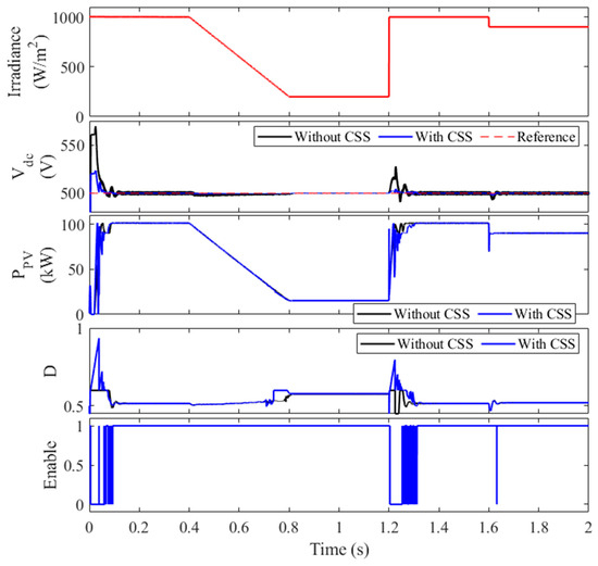
Figure 10.
Performance comparison of coordinated and uncoordinated control strategies.
A summary of the key performance metrics for both cases is provided in Table 4. The table clearly highlights the substantial improvement in DC-link voltage regulation achieved through the proposed coordination strategy. The uncoordinated control results, also presented in Table 4, further underscores the benefits of coordination, with all control methods showing improved performance under the coordinated scheme.
Table 4.
Performance comparison of coordinated and uncoordinated control strategies.
- iv.
- Comparison between SMC, Droop Power Control, and Predictive Control
This section evaluates the performance of SMC, Droop Power Control (DPC) [49], and Model Predictive Control (MPC) [35] within a coordinated control framework involving a boost converter and Voltage Source Inverter (VSI). The analysis focuses on transient and steady-state performance, specifically DC-link voltage regulation and power extraction.
SMC demonstrates superior performance across all metrics compared to DPC and MPC. As detailed in Table 4, SMC exhibits the lowest overshoot in DC-link voltage (523 V), closely followed by MPC (526 V) and DPC (537 V) under coordinated control. Furthermore, at a disturbance time of 1.2 s, SMC maintains the DC-link voltage at 504.3 V, indicating enhanced robustness against sudden disturbances, compared to 509.6 V for DPC and 507.4 V for MPC.
The standard deviation of the DC-link voltage, a measure of voltage stability, is significantly lower for SMC (5.92 V) compared to DPC (10.2 V) and MPC (8.17 V), highlighting its improved voltage regulation. Additionally, SMC achieves the highest average power output (70.3 kW), demonstrating its efficiency in power extraction.
Due to the lowest disturbance in the DC-link voltage, the harmonic associated with the SMC is much lower than the ones associated with the DPC and MPC techniques as shown in Table 4. The highest total harmonic distortion (THD) associated with MPC is 2.43% compared to 2.73% and 2.48% for DPC and MPC, respectively.
These results demonstrate that SMC, when implemented within a coordinated control framework, provides the most robust and efficient performance, characterized by lower overshoot, improved voltage stability, and higher power extraction compared to DPC and MPC.
Although the current work does not simulate grid disturbances such as voltage sags or phase imbalance, prior studies suggest that the SMC employed here provides a robust dynamic response under such scenarios due to its inherent insensitivity to system uncertainties [28,36]. Moreover, the coordination between the SMC of the boost converter and the VSI provides more confidence to the dynamic robustness of the proposed strategy to handle the disturbances of such scenarios.
5. Conclusions
In this study, a synergistic control strategy for three-phase grid-connected PV systems, combining a musical chairs algorithm (MCA) for maximum power point tracking (MPPT) with sliding mode control (SMC) for both the boost converter and the three-phase voltage source inverter (VSI) is proposed. This approach effectively enhances the stability of the DC-link voltage and improves the overall power quality of the PV system. The proposed strategy enables the MPPT to effectively track the MPP when the voltage is lower than the maximum allowable voltage. Meanwhile, in case the voltage goes above this value, the proposed strategy switched the control from the MPPT to the SMC of the boost converter to synergistically work with the VSI controller to reduce the DC-link voltage. The simulation results demonstrate that the proposed strategy significantly reduces voltage fluctuations and improves the transient response of the DC-link voltage under varying solar irradiance and grid conditions. By sharing the responsibility of maintaining the DC-link voltage between the boost converter and the VSI, the system achieves better performance and reliability. Furthermore, the proposed strategy reduces the size and cost of the DC-link capacitor, making the PV system more cost-effective and efficient. The use of SMC in both the boost converter and the VSI ensures robust control and stability, even under challenging operating conditions. Overall, the synergistic control strategy presented in this paper offers a promising solution for enhancing the power quality and stability of three-phase grid-connected PV systems.
Future research directions include integrating energy storage systems like batteries or supercapacitors to enhance system performance and reliability. Additionally, exploring advanced control techniques such as adaptive or fuzzy logic control can improve the system’s adaptability to varying conditions. Real-time implementation of FPGAs or DSPs is also a promising avenue for further development. By addressing these areas, the proposed control strategy can be optimized and applied to a wider range of PV system applications.
The proposed control strategy is scalable and can be extended to larger PV systems by tuning the SMC parameters accordingly and ensuring proper grid synchronization. Future work includes a detailed cost–benefit analysis to evaluate the trade-offs in system complexity, capacitor sizing, and control implementation costs.
Author Contributions
Conceptualization, Z.A.A. and A.M.E.; Methodology, Z.A.A. and A.M.E.; Software, Z.A.A. and A.M.E.; Validation, Z.A.A. and A.M.E.; Formal analysis, Z.A.A. and A.M.E.; Investigation, Z.A.A. and A.M.E.; Resources, Z.A.A. and A.M.E.; Data curation, A.M.E.; Writing—original draft, Z.A.A. and A.M.E.; Writing—review and editing, A.M.E.; Visualization, A.M.E.; Supervision, A.M.E.; Project administration, Z.A.A.; Funding acquisition, Z.A.A. All authors have read and agreed to the published version of the manuscript.
Funding
The authors extend their appreciation to the King Saud University for funding this work through the Researchers Supporting Project number (RSPD2025R596), King Saud University, Riyadh, Saudi Arabia.
Institutional Review Board Statement
Not applicable.
Informed Consent Statement
Not applicable.
Data Availability Statement
The data that support the findings of this study are available from the corresponding author upon reasonable request.
Conflicts of Interest
The authors declare no conflicts of interest.
Abbreviations
List of Abbreviations
| Abb. | Full Form | Abb. | Full Form |
| CPG | Constant Power Generation | P&O | Perturb and Observe |
| CSS | Control Selection Strategy | PI | Proportional-Integral |
| DSMC | Direct SMC | PLL | Phase-Locked Loop |
| ESR | Equivalent Series Resistance | PSCs | Partial Shading Conditions |
| FLC | Fuzzy Logic Controller | PSO | Particle Swarm Optimization |
| GWO | Grey Wolf Optimization | PV | Photovoltaic |
| LVRT | Low-Voltage Ride-Through | PWM | Pulse Width Modulation |
| MCA | Musical Chairs Algorithm | SMC | Sliding Mode Control |
| MPPT | Maximum Power Point Tracker | SMCI | SMC with Integral action |
| OBSMC | Observer-based Backstepping SMC | VSI | Voltage Source Inverter |
List of Symbols
| Symbol | Definition | Symbol | Definition |
| vPV | Terminal PV voltage | ed, eq | Park’s transformation of the grid voltages |
| iPV | PV current | va, vb, vc | Inverter output voltages |
| Cin | Input capacitor | ia, ib, ic | Three-phase output currents |
| Cout | DC-link capacitor | ea, eb, ec | Grid three phase voltages |
| vdc | DC-link voltage | Reference of d and q voltages | |
| L | Inductance of boost inductor | Reference of d and q currents | |
| RTL | Transmission line resistance | Parks transformation of the voltages at the output of the three-phase inverter. | |
| LTL | Transmission line inductance | Parks transformation of the grid currents | |
| d | Duty ratio of boost converter | idco | Output current from the DC-link capacitor |
| Reference DC-link voltage | iL | Inductor current of boost converter | |
| Three-phase grid voltages | fs | Switching frequency of the boost converter | |
| Three-phase grid currents | u | Switching state of the boost converter | |
| Reference of the grid voltages | Dmin, Dmax | Minimum and maximum allowable duty ratio of the boost converter | |
| ω | Angular velocity | VI | Vector of the inverter output voltage |
| θ | Phase angle | I | Inverter output current vector |
| ε | Predefined tolerance for change in the DC voltage | E | Vector of electric utility vector |
| ev | Error in DC-link voltage | x1, x2, x3 | State space variables of the SMC |
| ei | Error in PV current | σ | Sliding surface of the SMC |
References
- Raimi, D.; Zhu, Y.; Newell, R.G.; Prest, B.C.; Bergman, A. Global energy outlook 2023: Sowing the seeds of an energy transition. Resour. Future 2023, 1, 1–44. [Google Scholar]
- Baatiah, A.O.; Eltamaly, A.M.; Alotaibi, M.A. Improving photovoltaic MPPT performance through PSO dynamic swarm size reduction. Energies 2023, 16, 6433. [Google Scholar] [CrossRef]
- Guo, K.; Cui, L.; Mao, M.; Zhou, L.; Zhang, Q. An improved gray wolf optimizer MPPT algorithm for PV system with BFBIC converter under partial shading. IEEE Access 2020, 8, 103476–103490. [Google Scholar] [CrossRef]
- Eltamaly, A.M. A novel musical chairs algorithm applied for MPPT of PV systems. Renew. Sustain. Energy Rev. 2021, 146, 111135. [Google Scholar] [CrossRef]
- Rezk, H.; Eltamaly, A.M. A comprehensive comparison of different MPPT techniques for photovoltaic systems. Sol. Energy 2015, 112, 1–11. [Google Scholar] [CrossRef]
- Femia, N.; Petrone, G.; Spagnuolo, G.; Vitelli, M. Optimization of perturb and observe maximum power point tracking method. IEEE Trans. Power Electron. 2005, 20, 963–973. [Google Scholar] [CrossRef]
- Al-Wesabi, I.; Fang, Z.; Wei, Z.; Dong, H. Direct sliding mode control for dynamic instabilities in DC-link voltage of standalone photovoltaic systems with a small capacitor. Electronics 2022, 11, 133. [Google Scholar] [CrossRef]
- Memon, M.A.; Bhutto, G.M.; Buriro, E.A. Sizing of dc-link capacitor for a grid connected solar photovoltaic inverter. Indian J. Sci. Technol 2020, 13, 2272–2281. [Google Scholar] [CrossRef]
- Sangwongwanich, A.; Shen, Y.; Chub, A.; Liivik, E.; Vinnikov, D.; Wang, H.; Blaabjerg, F. Design for accelerated testing of DC-link capacitors in photovoltaic inverters based on mission profiles. IEEE Trans. Ind. Appl. 2020, 57, 741–753. [Google Scholar] [CrossRef]
- Kumar, N.B.; Urundady, V. Sliding mode controller with integral action for dc-link voltage control of grid-integrated domestic photovoltaic systems. Arab. J. Sci. Eng. 2020, 45, 6583–6600. [Google Scholar] [CrossRef]
- Bhattacharyya, S.; Samanta, S. DC link voltage control based power management scheme for standalone PV systems. In Proceedings of the 2018 IEEE International Conference on Power Electronics, Drives and Energy Systems (PEDES), Chennai, India, 18–21 December 2018; pp. 1–5. [Google Scholar]
- Thammasiriroj, W.; Nuchkrua, T.; Ruayariyasub, S. Sliding mode control for stabilizing DC-link of DC-DC converter in photovoltaic systems. In Proceedings of the The 2nd International Symposium on Power Electronics for Distributed Generation Systems, Hefei, China, 16–18 June 2010; pp. 347–351. [Google Scholar]
- Messo, T.; Jokipii, J.; Puukko, J.; Suntio, T. Determining the value of DC-link capacitance to ensure stable operation of a three-phase photovoltaic inverter. IEEE Trans. Power Electron. 2013, 29, 665–673. [Google Scholar] [CrossRef]
- Mohamed, S.R.; Jeyanthy, P.A.; Devaraj, D.; Shwehdi, M.H.; Aldalbahi, A. DC-link voltage control of a grid-connected solar photovoltaic system for fault ride-through capability enhancement. Appl. Sci. 2019, 9, 952. [Google Scholar] [CrossRef]
- Kermadi, M.; Salam, Z.; Eltamaly, A.M.; Ahmed, J.; Mekhilef, S.; Larbes, C.; Berkouk, E. Recent developments of MPPT techniques for PV systems under partial shading conditions: A critical review and performance evaluation. IET Renew. Power Gener. 2020, 14, 3401–3417. [Google Scholar] [CrossRef]
- Eltamaly, A.M. Performance of MPPT techniques of photovoltaic systems under normal and partial shading conditions. In Advances in Renewable Energies and Power Technologies; Elsevier: Amsterdam, The Netherlands, 2018; pp. 115–161. [Google Scholar]
- Laabidi, H.; Jouini, H.; Mami, A. Sliding mode control for PV-wind hybrid system connected to grid. In Proceedings of the International Conference on Green Energy & Environmental Engineering (GEEE-2018), Proceeding of Engineering and technology-PET, Sousse, Tunisia, 28–30 April 2018; pp. 39–44. [Google Scholar]
- Snoussi, J.; Elghali, S.B.; Outbib, R.; Mimouni, M.F. Sliding mode control for frequency-based energy management strategy of hybrid storage system in vehicular application. In Proceedings of the International Symposium on Power Electronics, Electrical Drives, Automation and Motion (SPEEDAM), Capri, Italy, 22–24 June 2016; pp. 1109–1114. [Google Scholar]
- Benadli, R.; Sellami, A. Sliding mode control of a photovoltaic-wind hybrid system. In Proceedings of the 2014 International Conference on Electrical Sciences and Technologies in Maghreb (CISTEM), Tunis, Tunisia, 3–6 November 2014; pp. 1–8. [Google Scholar]
- Anto, E.K.; Asumadu, J.A.; Okyere, P.Y. PID control for improving P&O-MPPT performance of a grid-connected solar PV system with Ziegler-Nichols tuning method. In Proceedings of the IEEE 11th Conference on Industrial Electronics and Applications (ICIEA), Hefei, China, 5–7 June 2016; pp. 1847–1852. [Google Scholar]
- Guo, L.; Hung, J.Y.; Nelms, R.M. Comparative evaluation of sliding mode fuzzy controller and PID controller for a boost converter. Electr. Power Syst. Res. 2011, 81, 99–106. [Google Scholar] [CrossRef]
- Eltamaly, A.M. Modeling of fuzzy logic controller for photovoltaic maximum power point tracker. In Proceedings of the Solar Future 2010 Conference, Istanbul, Turkey, 11–12 February 2010. [Google Scholar]
- Chakraborty, S.; Weiss, M.D.; Simoes, M.G. Distributed intelligent energy management system for a single-phase high-frequency AC microgrid. IEEE Trans. Ind. Electron. 2007, 54, 97–109. [Google Scholar] [CrossRef]
- Sira-Ramírez, H.; Silva-Ortigoza, R. Sliding Mode∑-Δ Modulation Control of the Boost Converter. Asian J. Control 2005, 7, 349–355. [Google Scholar] [CrossRef]
- Viswambharan, A.; Errouissi, R.; Debouza, M.; Shareef, H. Experimental Verification of Disturbance Observer-Based Backstepping Control for DC–DC Boost Converter. IEEE Trans. Circuits Syst. I Regul. Pap. 2023, 70, 5520–5533. [Google Scholar] [CrossRef]
- Nizami, T.K.; Chakravarty, A. Neural network integrated adaptive backstepping control of DC-DC boost converter. IFAC-PapersOnLine 2020, 53, 549–554. [Google Scholar] [CrossRef]
- Abouda, S.; Essounbouli, N.; Chaari, A.; Koubaa, Y. PID and Sliding Mode Control-SMC for a Motor-pump Voltage in a Photovoltaic-PV System based on MPPT Controller. Int. J. Comput. Appl. 2013, 73, 44–49. [Google Scholar] [CrossRef]
- Khan, R.; Khan, L.; Ullah, S.; Sami, I.; Ro, J.-S. Backstepping based super-twisting sliding mode MPPT control with differential flatness oriented observer design for photovoltaic system. Electronics 2020, 9, 1543. [Google Scholar] [CrossRef]
- Idrissi, R.E.; Abbou, A.; Mokhlis, M. Backstepping Integral Sliding Mode Control Method for Maximum Power Point Tracking for Optimization of PV System Operation Based on High-Gain Observer. Int. J. Intell. Eng. Syst. 2020, 13, 133–144. [Google Scholar] [CrossRef]
- Seo, S.-W.; Choi, H.H. Digital implementation of fractional order PID-type controller for boost DC–DC converter. IEEE Access 2019, 7, 142652–142662. [Google Scholar] [CrossRef]
- Johnson, R.S.; Altin, B.; Sanfelice, R.G. Hybrid Adaptive Control for the DC-DC Boost Converter. IFAC-PapersOnLine 2021, 54, 73–78. [Google Scholar] [CrossRef]
- Kobaku, T.; Jeyasenthil, R.; Sahoo, S.; Ramchand, R.; Dragicevic, T. Quantitative feedback design-based robust PID control of voltage mode controlled DC-DC boost converter. IEEE Trans. Circuits Syst. II Express Briefs 2020, 68, 286–290. [Google Scholar] [CrossRef]
- Van, T.H.; Le Van, T.; Thi, T.M.N.; Duong, M.Q.; Sava, G.N. Improving the output of DC-DC converter by phase shift full bridge applied to renewable energy. Rev. Roum. Des Sci. Tech.—Sér. Électrotech. Énerg. 2021, 66, 175–180. [Google Scholar]
- Muktiadji, R.F.; Ramli, M.A.M.; Bouchekara, H.R.E.H.; Milyani, A.H.; Rawa, M.; Seedahmed, M.M.A.; Budiman, F.N. Control of boost converter using observer-based backstepping sliding mode control for DC microgrid. Front. Energy Res. 2022, 10, 828978. [Google Scholar] [CrossRef]
- Ahmed, M.; Harbi, I.; Kennel, R.; Rodriguez, J.; Abdelrahem, M. Model-based maximum power point tracking algorithm with constant power generation capability and fast DC-link dynamics for two-stage PV systems. IEEE Access 2022, 10, 48551–48568. [Google Scholar] [CrossRef]
- Gohar Ali, H.; Vilanova Arbos, R.; Herrera, J.; Tobón, A.; Peláez-Restrepo, J. Non-linear sliding mode controller for photovoltaic panels with maximum power point tracking. Processes 2020, 8, 108. [Google Scholar] [CrossRef]
- Montoya, D.G.; Paja, C.A.R.; Giral, R. A new solution of maximum power point tracking based on sliding mode control. In Proceedings of the IECON 2013-39th Annual Conference of the IEEE Industrial Electronics Society, Vienna, Austria, 10–13 November 2013; pp. 8350–8355. [Google Scholar]
- Montoya, D.G.; Ramos-Paja, C.A.; Giral, R. Improved design of sliding-mode controllers based on the requirements of MPPT techniques. IEEE Trans. Power Electron. 2015, 31, 235–247. [Google Scholar] [CrossRef]
- Noureldeen, O.; Ibrahim, A.M.A. Low-voltage ride-through capability enhancement of a grid-connected photovoltaic/wind hybrid power system. In Proceedings of the Nineteenth International Middle East Power Systems Conference (MEPCON), Cairo, Egypt, 19–21 December 2017; pp. 786–795. [Google Scholar]
- Kumar, V.; Singh, M. Sensorless DC-link control approach for three-phase grid integrated PV system. Int. J. Electr. Power Energy Syst. 2019, 112, 309–318. [Google Scholar] [CrossRef]
- Dhouib, B.; Zdiri, M.A.; Alaas, Z.; Hadj Abdallah, H. Fault Analysis of a Small PV/Wind Farm Hybrid System Connected to the Grid. Appl. Sci. 2023, 13, 1743. [Google Scholar] [CrossRef]
- Trejos, A.; Gonzalez, D.; Ramos-Paja, C.A. Modeling of step-up grid-connected photovoltaic systems for control purposes. Energies 2012, 5, 1900–1926. [Google Scholar] [CrossRef]
- Bianconi, E.; Calvente, J.; Giral, R.; Mamarelis, E.; Petrone, G.; Ramos-Paja, C.A.; Spagnuolo, G.; Vitelli, M. Perturb and observe MPPT algorithm with a current controller based on the sliding mode. Int. J. Electr. Power Energy Syst. 2013, 44, 346–356. [Google Scholar] [CrossRef]
- Bianconi, E.; Calvente, J.; Giral, R.; Mamarelis, E.; Petrone, G.; Ramos-Paja, C.A.; Spagnuolo, G.; Vitelli, M. A fast current-based MPPT technique employing sliding mode control. IEEE Trans. Ind. Electron. 2012, 60, 1168–1178. [Google Scholar] [CrossRef]
- Spiazzi, G.; Mattavelli, P. Sliding-mode control of switched-mode power supplies. In The Power Electronics Handbook; CRC Press: Boca Raton, FL, USA, 2018; pp. 8-1–8-24. [Google Scholar]
- Touil, S.A.; Boudjerda, N.; Boubakir, A.; El Khamlichi Drissi, K. A sliding mode control and artificial neural network based MPPT for a direct grid-connected photovoltaic source. Asian J. Control 2019, 21, 1892–1905. [Google Scholar] [CrossRef]
- Chen, Y.-M.; Chang, C.-H.; Wu, H.-C. DC-link capacitor selections for the single-phase grid-connected PV system. In Proceedings of the International Conference on Power Electronics and Drive Systems (PEDS), Taipei, Taiwan, 2–5 November 2009; pp. 72–77. [Google Scholar]
- Solar, C. CS5P-220M. Available online: https://www.pvxchange.com/Solar-Modules/Canadian-Solar/CS5P-220M_1-2103721 (accessed on 10 December 2024).
- Paspatis, A.G.; Konstantopoulos, G.C. Voltage support under grid faults with inherent current limitation for three-phase droop-controlled inverters. Energies 2019, 12, 997. [Google Scholar] [CrossRef]


Disclaimer/Publisher’s Note: The statements, opinions and data contained in all publications are solely those of the individual author(s) and contributor(s) and not of MDPI and/or the editor(s). MDPI and/or the editor(s) disclaim responsibility for any injury to people or property resulting from any ideas, methods, instructions or products referred to in the content. |
© 2025 by the authors. Licensee MDPI, Basel, Switzerland. This article is an open access article distributed under the terms and conditions of the Creative Commons Attribution (CC BY) license (https://creativecommons.org/licenses/by/4.0/).