
CO2 Employment as Refrigerant Fluid with a Low Environmental Impact. Experimental Tests on Arugula and Design Criteria for a Test Bench


Abstract
:1. Introduction
1.1. Law and Technical Aspects Regarding Greenhouse Gas Emissions of Refrigerant Fluids

| Regulation (EC) n. | Year | Standard/requirements |
|---|---|---|
| 842 | 2006 | Containment, use, recovery and destruction of fluorinated greenhouse gases listed in attachment I; labeling and disposal of products and equipment containing those gases; communication of information on those gases. |
| 516 | 2007 | Leakage checking requirements for stationary refrigeration, air-conditioning and heat pumps. |
| 1797 | 2007 | Leakage checking requirements for stationary fire protection system containing certain fluorinated greenhouse gases. |
| 303–306 | 2008 | Minimum requirements and conditions for mutual identification for the certification of companies and personnel in regard to: stationary refrigeration, air-conditioning and heat pumps, stationary fire protection system and fire extinguishers, containing certain fluorinated greenhouse gases. |
| 307 | 2008 | Requirements for training programs for personnel in regards to air-conditioning systems containing certain fluorinated gases. |
| 517 | 2014 | Conditions placed on the trade of products and equipment that contain fluorinated greenhouses gases; conditions for use of greenhouses gases; limits placed on the trade of hydrofluorocarbons; institution of a quota market for the trade of hydrofluorocarbons; prevention of emissions, leakage checks, installation of leak detection (automatic) systems, registry, of F-Gases. |
- (1)
- Studying the creation of new synthetic refrigerant fluids that can satisfy plant and environmental needs; and
- (2)
- Studying how to adapt plants and machinery to the new fluids, in particular natural ones.
- high latent heat value during phase transition at evaporation temperature, which, combined with a high density, guarantees the necessity of suitable capacity at the same required refrigerating power;
- capacity to evaporate and condensate at temperatures and pressures that are suitable to the field of use;
- solubility, in the gaseous phase, and miscibility, in the liquid phase, with lubricating oil; and
- ratio between condensation and evaporation pressure, which should not be too high, so as to reduce the consumption of energy used for compression.
| Harmless to the ozone layer |
|---|
| GWP = 1 (considering CO2 as recycled or recovered component from industrial by-production) |
| Non-flammable and non-toxic except in the case of high concentrations and poorly ventilated rooms |
| Compatible with all common materials |
| Corrosive only in the presence of water, except for stainless steel |
| Volumetric refrigerating effect at low temperatures greater than other fluids |
| Lower compressor flow rate, but higher pressure (even at low temperatures) |
| High thermal conductivity, both in liquid and steam phases |
| High specific heat guarantees |
| High thermal exchange coefficients in heat exchangers |
| Critical temperature of 31 °C |
| Subcritical refrigeration cycle comparable to that of other fluids |
- low toxicity and flammability in air;
- chemical inertia to the most commonly used materials in refrigeration circuits;
- low ODP (Ozone Depletion Potential); and
- low GWP (Global Warming Potential) or TEWI (Total Equivalent Warming Impact), a more complete version of GWP, which depends on the type of fluid and on the plant. In fact, apart from taking into consideration the direct effect the fluid has when released into the atmosphere (following its use in the plant), it also qualifies its indirect effect, which is caused by carbon dioxide emissions created by the production of the energy consumed by the plant during lifecycle. Then it is evident that, optimizing energetic consumption of a refrigeration plant means reducing TEWI [3,4,5].

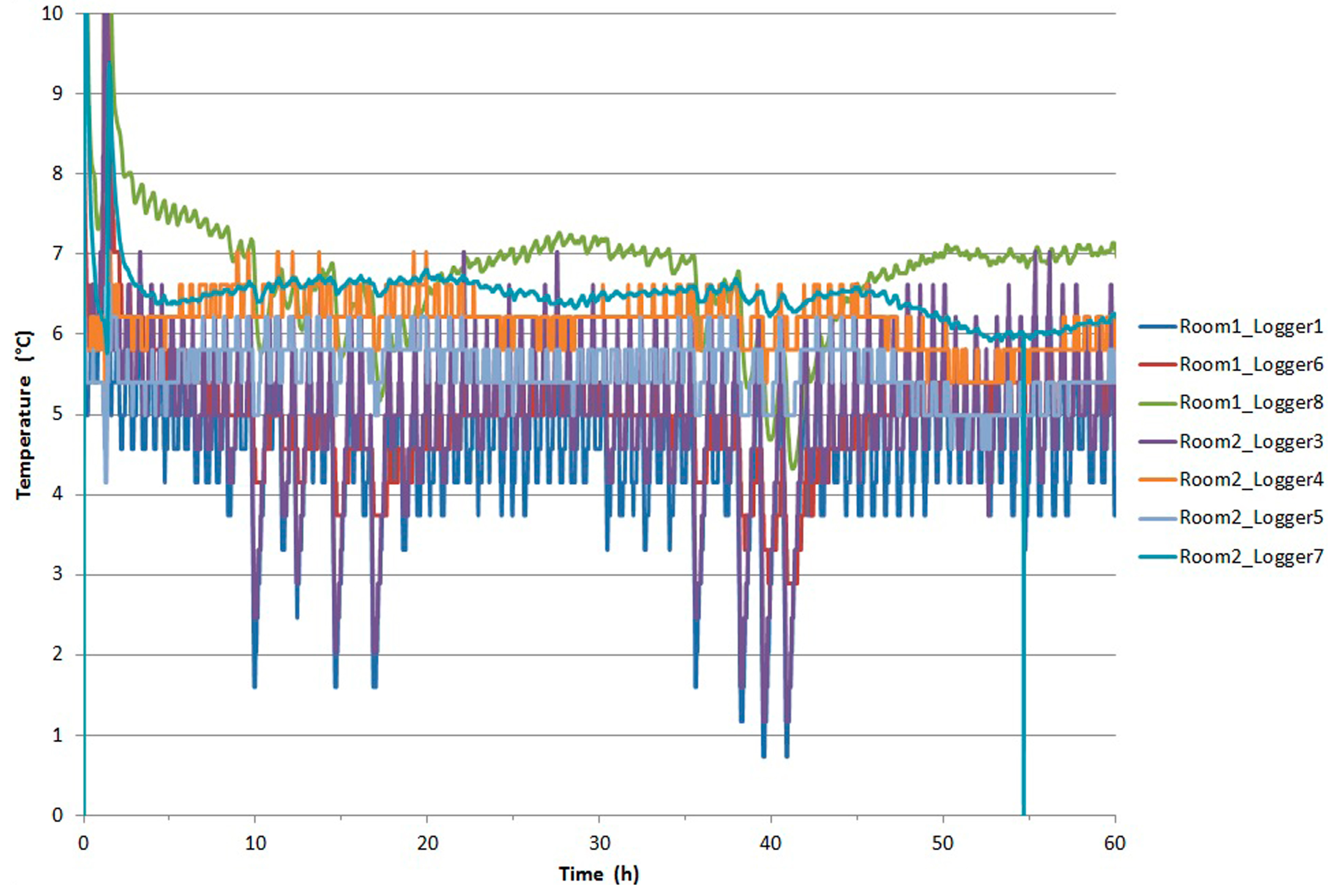
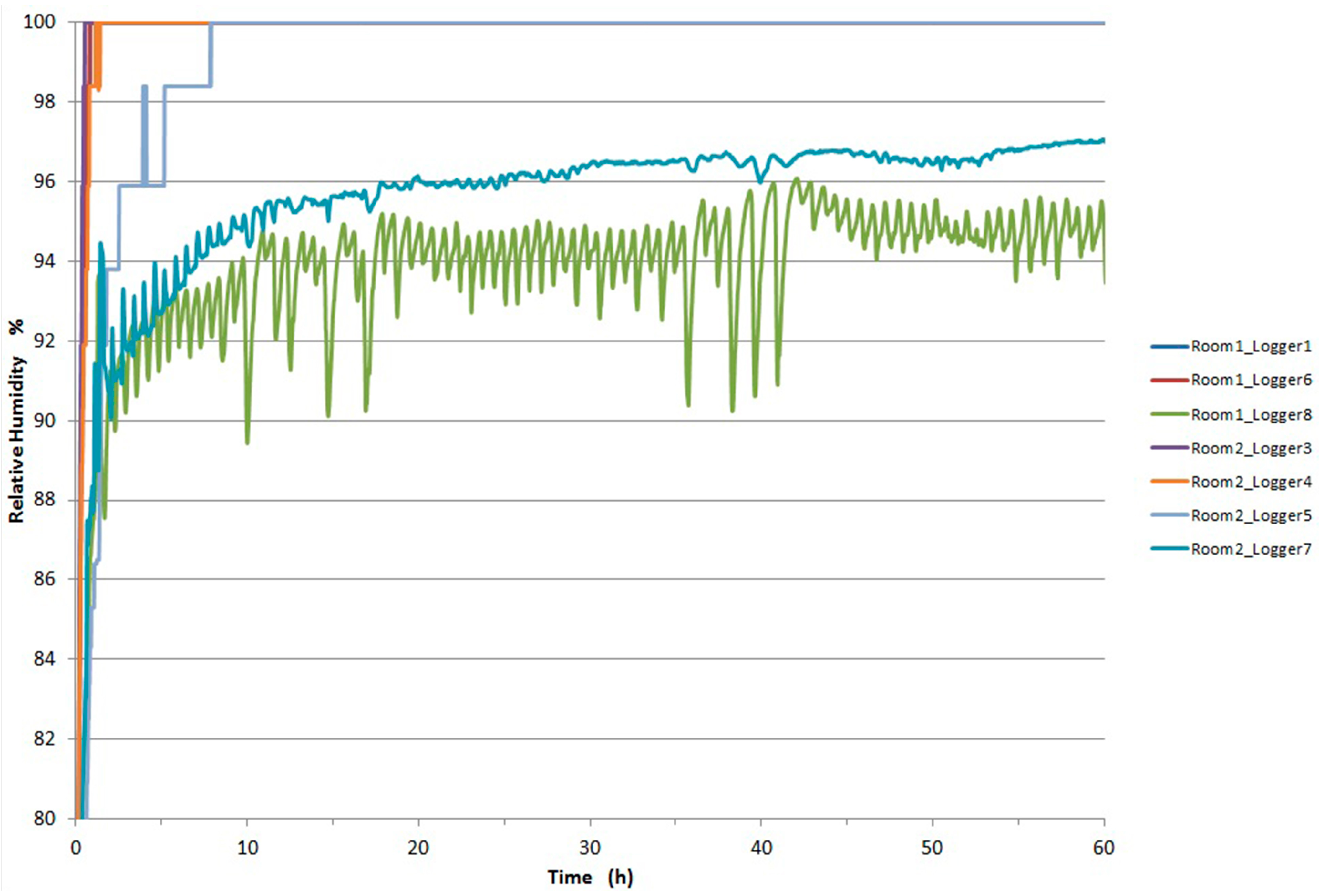
1.2. Control of Temperature and RH during Food Storage
| Time | Temperature (°C) | Relative humidity (%) |
|---|---|---|
| Draining | ||
| Day 1 | 22 | 65 |
| Day 2 | 21 | 70 |
| Day 3 | 20 | 75 |
| Day 4 | 19 | 80 |
| Drying | ||
| Day 1 | 19.5 | 60 |
| Day 2 | 17.5 | 65 |
| Day 3 | 15.5 | 70 |
| Day 4 | 14.5 | 75 |
| Day 5 | 13.5 | 80 |
| Day 6 | 12.5 | 80 |
| Aging | ||
| Total time: 120 days | 12.5 | 80 |
| Storage | 4 | - |
2. Experimental Section
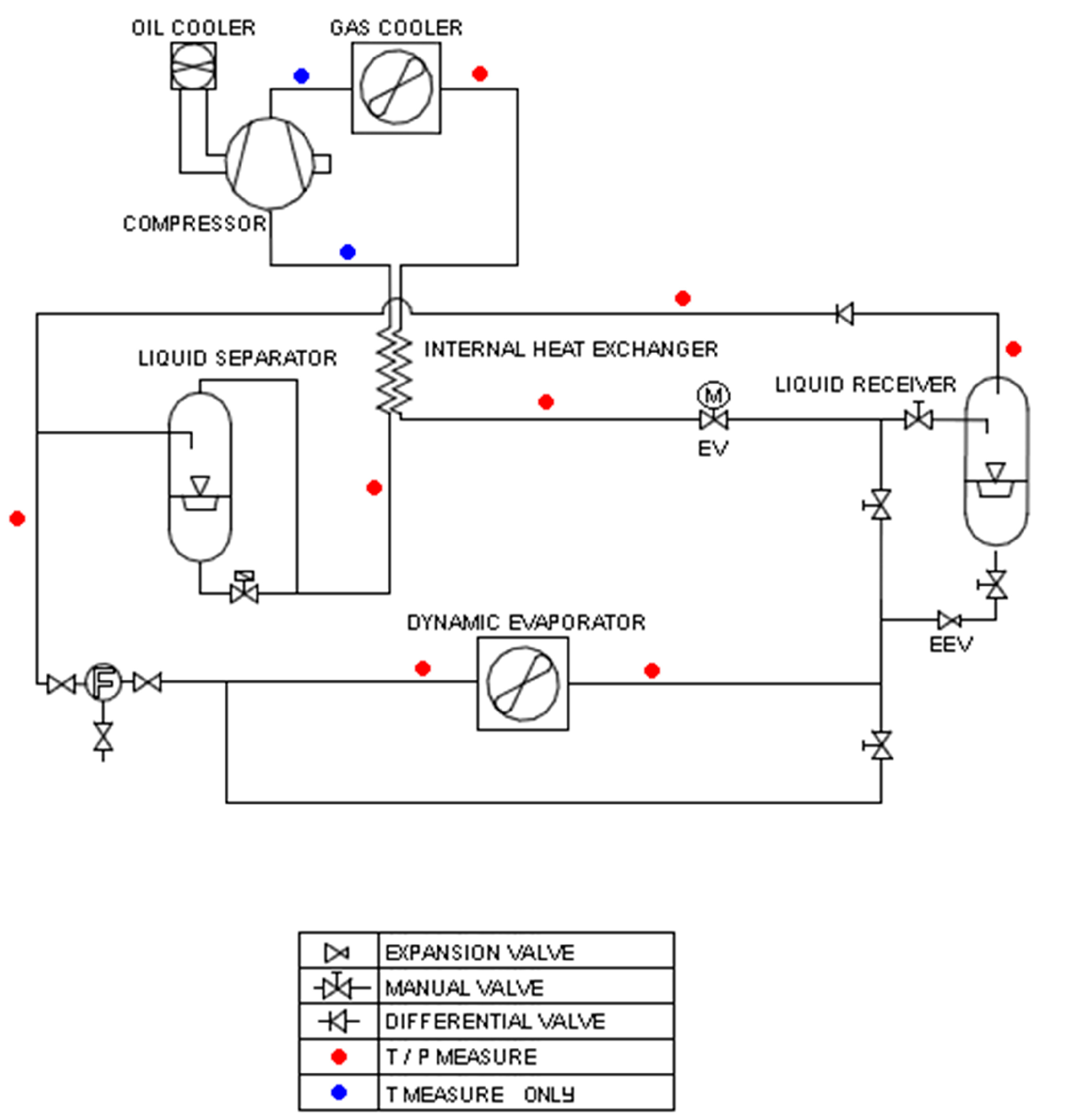
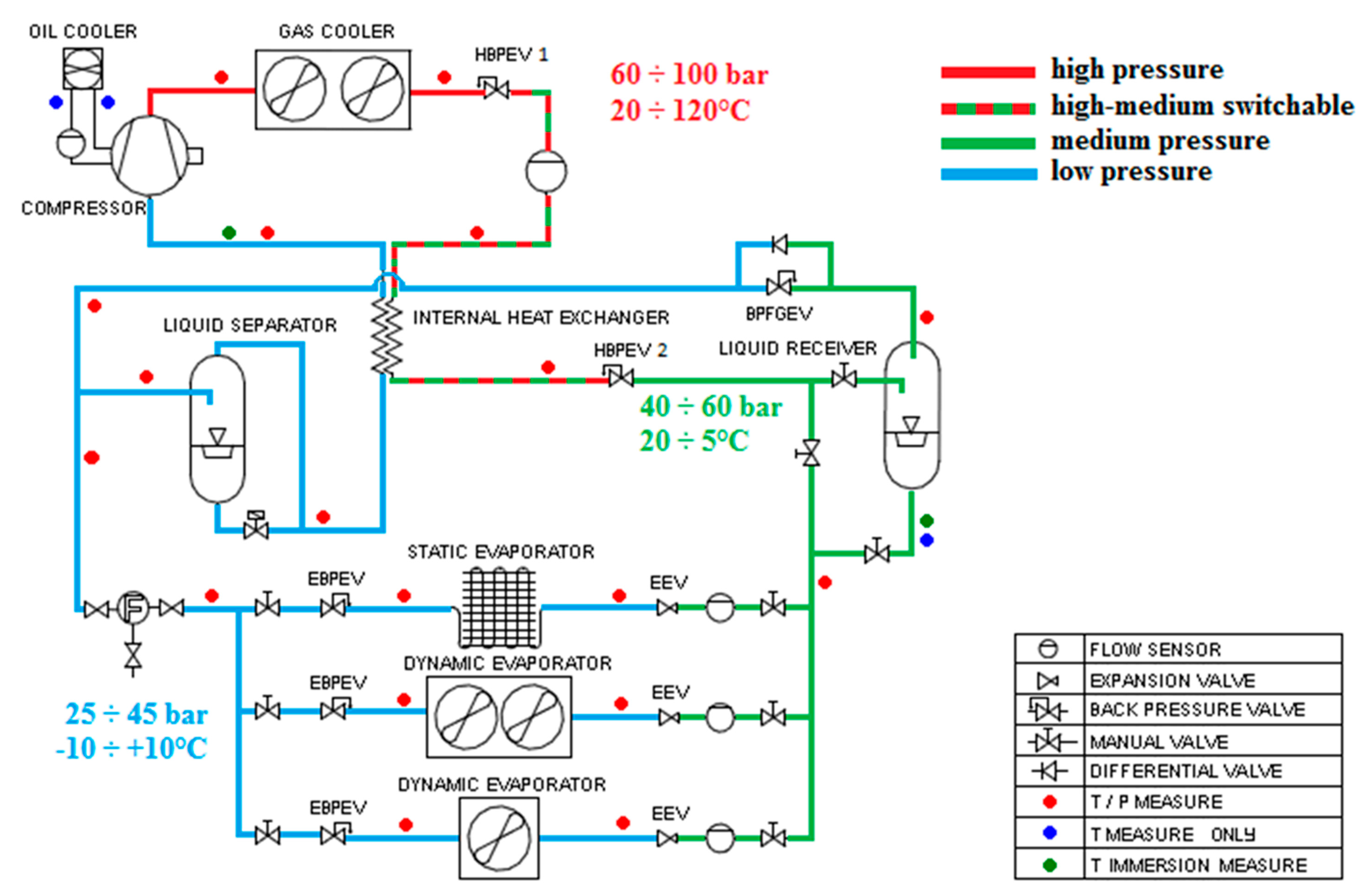
2.1. Basic Experimental CO2 Plant

- R22 is quite efficient, but it cannot no longer be used;
- R134A and R410A, substitutes of R22, are as efficient as R22; and
- R744 (CO2) is a little less efficient than all the previous fluids (COPR744 ≈ 0.7 COPR134A), but it is characterized by a quite higher density (ρR744 > 3 ρR410A) allowing the use of quite smaller compressors.

| Fluid | COP | Density (ρ) (kg/m3) |
|---|---|---|
| R22 | 7.22 | 24.0 |
| R134A | 7.31 | 16.7 |
| R410A | 7.03 | 33.8 |
| R744 | 5.21 | 107 |
2.2. Experimental Tests

- CO2 based plant test with proposals for improvements;
- system test used for data acquisition and significant CO2 plant parameters control; and
- temperature stratification (CO2 modules).
- appearance (sensorial evaluation) using a scale from 5 (excellent) to 1 (very poor, inedible);
- color, valued through hyperspectral images acquired by a spectral scanner and later processed for the L*,a* and b* CIE parameter calculation using a specific software. Data were expressed as ΔE* = [(L0* – L*) + (a0* – a*) + (b0* – b*)]1/2 where L0*, a0* and b0* are the color parameters of the fresh sample; weight loss percentage over time; and shear strength to evaluate turgidity losses using a Instron Universal Testing Machine equipped with a Kramer shear cell, and measuring the maximum force required by 5 blades to advance through a 5 grams sample of arugula at 0.8 mm/s.
Statistical Analysis
3. Results and Discussion
3.1. Results and Discussion of Experimental Tests
| ΔE * | Weight loss (%) | Texture (N) | ||||
|---|---|---|---|---|---|---|
| Storage condition | ||||||
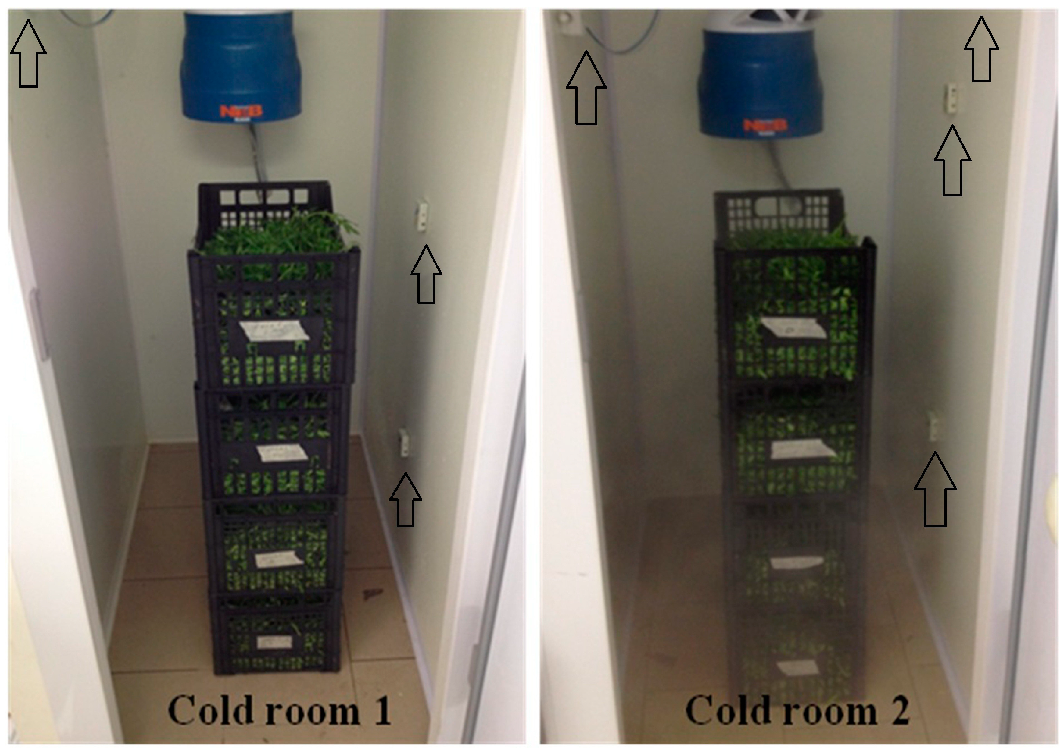
| COLD Room 1 | 15.03 | b | −2.33 | b | 165.16 | b |
| COLD Room 2 | 15.37 | b | −1.22 | b | 191.08 | a |
| CTRL Room | 20.77 | a | 8.86 | a | 212.41 | a |
| Storage time | ||||||
| 4 days | 8.22 | C | 1.12 | AB | 178.63 | |
| 7 days | 20.64 | B | 0.61 | B | 190.97 | |
| 11 days | 22.31 | A | 3.31 | A | 199.05 | |
| Storage condition | **** | **** | **** | |||
| Storage time | **** | * | ns | |||
| Storage condition × storage time | **** | ns | ns | |||


- (1)
- The correct behavior of the devices specially designed for the fluid used and conditioning needs have ensured the required plant performance, in relation to the recommended storage conditions, of the rocket leaves.
- (2)
- With regard to thermodynamic problems that characterize CO2 based plants, the condensing section of the refrigeration system has given extremely significant results including in the external temperature critical condition.
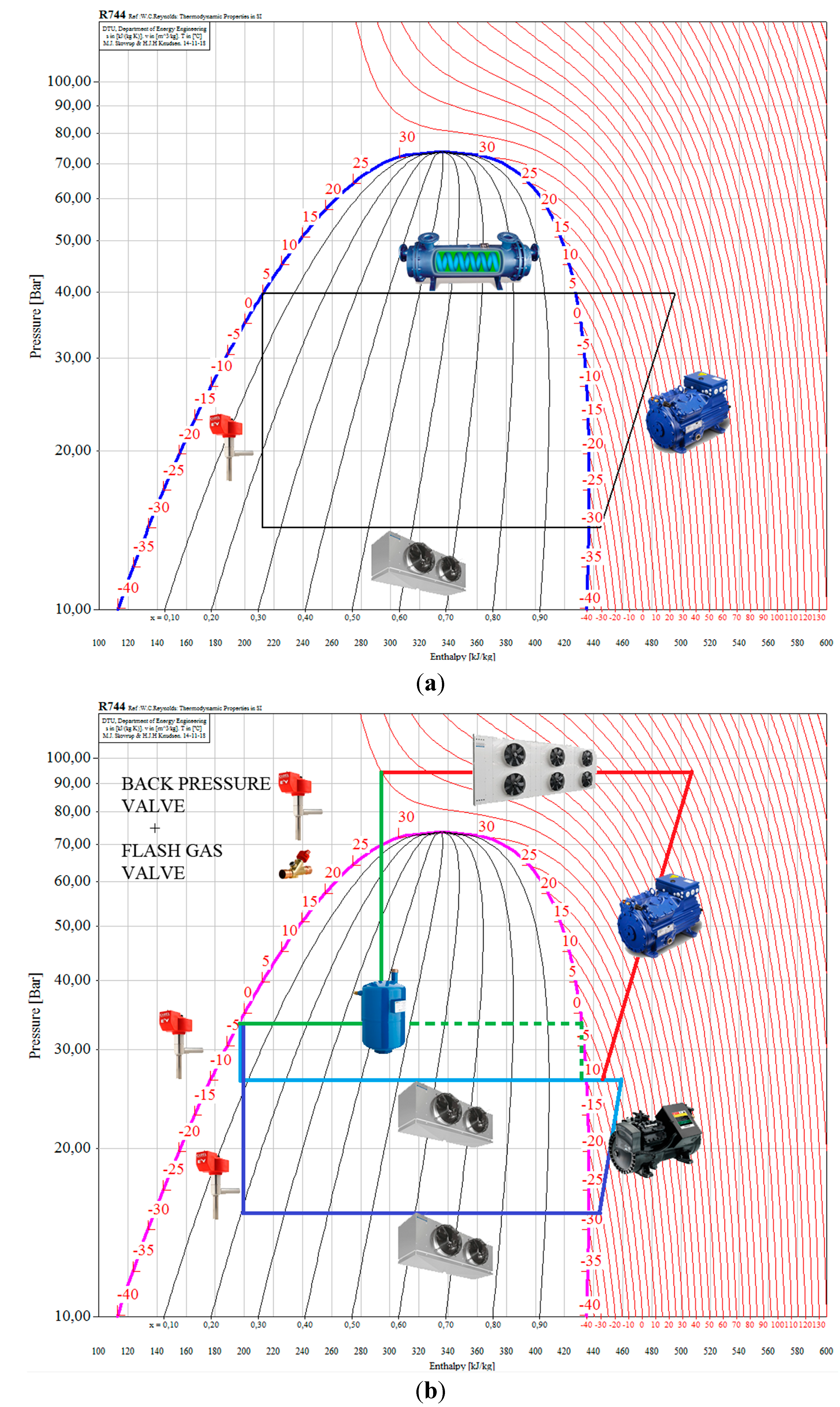
- control of the dew point immediately after the evaporative coil followed by an air heating system by controlling the evaporation pressure independently from the other components; and
- separate control of the pressure in the condensing–gas cooler section to achieve the optimal value of the global efficiency of the plant.
- (a)
- solenoid valve insertion upstream of each evaporator with the possibility to stop a refrigeration circuit independently from the other, improving cold room flexibility;
- (b)
- measurements of CO2 concentration contained in the cold room air, with the aim to control the microclimatic condition during preparation of meat based products;
- (c)
- system for internal air replacement of cooling rooms; and
- (d)
- insertion of an air heating system to integrate the independent temperature and humidity control, which is helpful during drying and maturing phases for which only a refrigeration plant is insufficient, due to particular humidity values and specifics requirements on the base of the conserved product type.
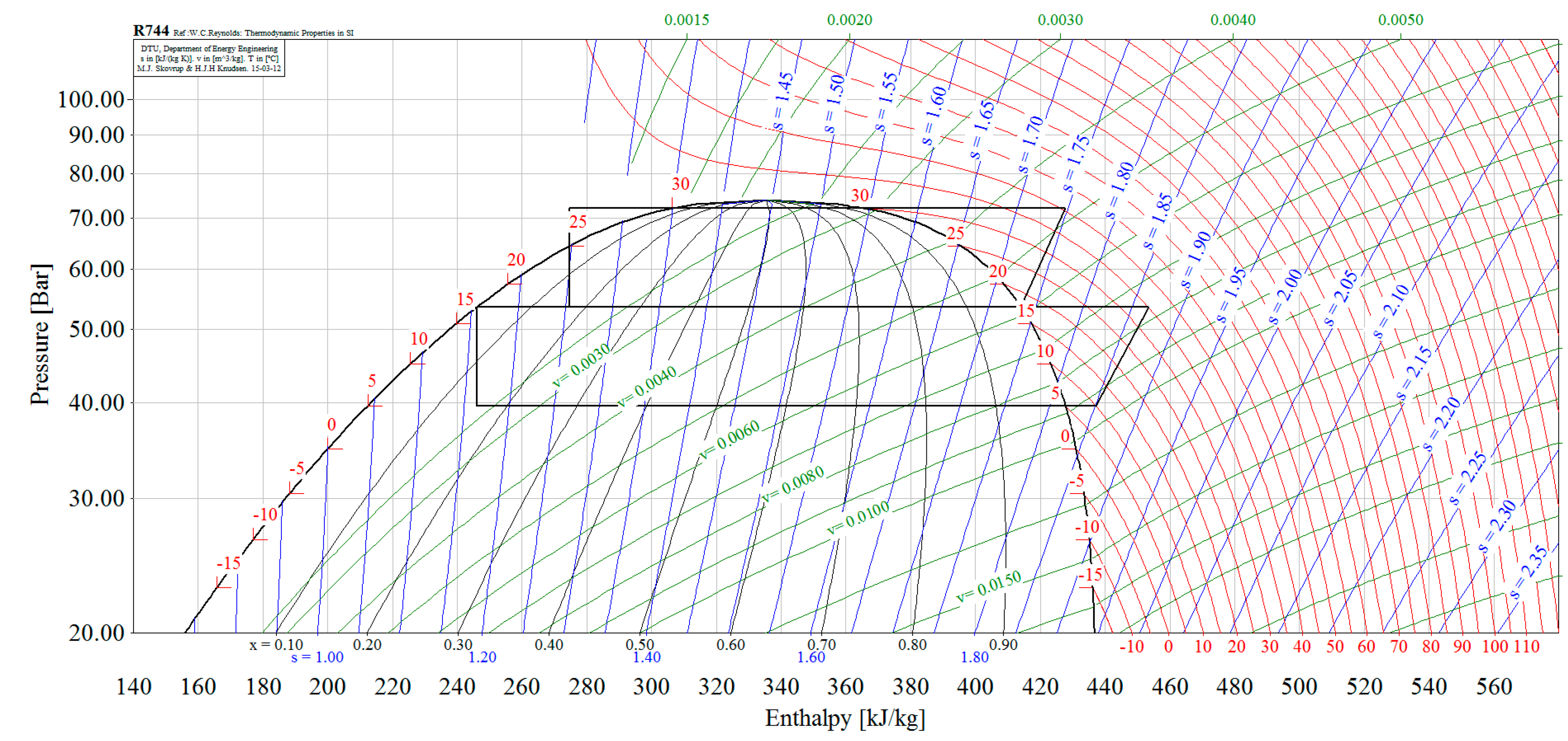
3.2. Optimization of Plant Configuration

4. Conclusions
- •
- COP maximization, to obtain the minimum energetic impact with a uniform cold produced;
- •
- high pressure heat recovery;
- •
- map plant fluid evolution in a multi-dimensional space variable, which can be monitored and controlled; and
- •
- optimization of the plant, also in function of TEWI index.
Acknowledgments
Author Contributions
Conflicts of Interest
References
- Hummel, K.E.; Nelson, T.P.; Thompson, P.A. Survey of the use and emissions of chlorofluorocarbons from large chillers. ASHRAE Trans. 1991, 97, 416–421. [Google Scholar]
- Sand, J.R.; Fischer, S.K.; Baxter, V.D. Energy and Global Warming Impacts of HFC Refrigerants and Emerging Technologies; Oak Ridge National Laboratory: Oak Ridge, TN, USA, 1997; pp. 5–60. [Google Scholar]
- Refrigeranti a basso GWP. Available online: http://www.associazioneatf.org/newsletter%20AREA/AREA%20-%20PP%20Low%20GWP%20refrigerants%20(110629)_ITA.pdf (accessed on 14 March 2015).
- Calm, J.M. The next generation of refrigerants—Historical review, considerations, and outlook. Int. J. Refrig. 2008, 31, 1123–1133. [Google Scholar] [CrossRef]
- Sârbu, I.; Valea, E.S. Past, present and future perspectives of refrigerants in air-conditioning, refrigeration and heat pump applications. WSEAS Trans. Heat Mass Transf. 2014, 9, 27–38. [Google Scholar]
- Suamir, I.N.; Tassou, S.A.; Marriott, D. Integration of CO2 refrigeration and trigeneration systems for energy and GHG emission savings in supermarkets. Int. J. Refrig. 2012, 35, 407–417. [Google Scholar] [CrossRef]
- Fernandez, N.; Hwang, Y.; Radermacher, R. Comparison of CO2 heat pump water heater performance with baseline cycle and two high COP cycles. Int. J. Refrig. 2010, 33, 635–644. [Google Scholar] [CrossRef]
- Sánchez, D.; Patiño, J.; Sanz-Kock, C.; Llopis, R.; Cabello, R. Energetic evaluation of a CO2 refrigeration plant working in supercritical and subcritical conditions. Appl. Therm. Eng. 2014, 66, 227–238. [Google Scholar] [CrossRef]
- Calm, J.M. Emissions and environmental impacts from air-conditioning and refrigeration systems. Int. J. Refrig. 2002, 25, 293–305. [Google Scholar] [CrossRef]
- Abed, A.M.; Sopian, K.; Alghoul, M.A.; Al-Shamani, A.N.; Ruslan, M.; Mat, S. Parametric study of single effect combined absorption-ejector cooling system. WSEAS Trans. Heat Mass Transf. 2014, 9, 95–101. [Google Scholar]
- Minetto, S.; Girotto, S.; Rossetti, A.; Marinetti, S. Experience with ejector work recovery and auxiliary compressors in CO2 refrigeration systems. Technological aspects and application perspectives. In Proceedings of the Ammonia Refrigeration Technology International Conference, Ohrid, Macedonia, 16–18 April 2015. in press.
- Bansal, P. A review e Status of CO2 as a low temperature refrigerant: Fundamentals and R&D opportunities. Appl. Therm. Eng. 2012, 41, 18–29. [Google Scholar] [CrossRef]
- Elbel, S. Historical and present developments of ejector refrigeration systems with emphasis on transcritical carbon dioxide air-conditioning applications. Int. J. Refrig. 2011, 34, 1545–1561. [Google Scholar] [CrossRef]
- Manjili, F.E.; Yavari, M.A. Performance of a new two-stage multi-intercooling transcritical CO2 ejector refrigeration cycle. Appl. Therm. Eng. 2012, 40, 202–209. [Google Scholar] [CrossRef]
- Sarkar, J.; Agrawal, N. Performance optimization of transcritical CO2 cycle with parallel compression economization. Int. J. Refrig. 2011, 49, 838–843. [Google Scholar]
- Ge, Y.T.; Tassou, S.A. Thermodynamic analysis of transcritical CO2 booster refrigeration systems in supermarket. Energy Convers. Manag. 2011, 52, 1868–1875. [Google Scholar] [CrossRef]
- Calm, J.M. Comparative efficiencies and implications for greenhouse gas emissions of chiller refrigerants. Int. J. Refrig. 2006, 29, 833–841. [Google Scholar] [CrossRef]
- Sánchez, D.; Cabello, R.; Llopis, R.; Torrella, E. Development and validation of a finite element model for water—CO2 coaxial gas-coolers. Appl. Energy 2012, 93, 637–647. [Google Scholar] [CrossRef]
- Del Caro, A.; Piga, A.; Vacca, V.; Agabbio, M. Changes of flavonoids, vitamin C and antioxidant capacity in minimally processed citrus segments and juices during storage. Food Chem. 2004, 84, 99–105. [Google Scholar] [CrossRef]
- Cortés, C.; Torregrosa, F.; Esteve, M.J.; Frígola, A. Carotenoid profile modification during refrigerated storage in untreated and pasteurized orange juice and orange juice treated with high intensity pulsed electric fields. J. Agric. Food Chem. 2006, 54, 6247–6254. [Google Scholar] [CrossRef] [PubMed]
- Di Nicola, G.; Polonara, F.; Stryjek, R.; Arteconi, A. Performance of cascade cycles working with blends of CO2 + natural refrigerants. Int. J. Refrig. 2011, 34, 1436–1445. [Google Scholar] [CrossRef]
- Bell, I.H.; Wronski, J.; Quoilin, S.; Lemort, V. Pure and Pseudo-pure fluid thermophysical property evaluation and the open-source thermophysical property library coolprop. Ind. Eng. Chem. Res. 2014, 53, 2498–2508. [Google Scholar] [CrossRef] [PubMed] [Green Version]
- Løkke, M.M.; Seefeldt, H.F.; Edelenbos, M. Freshness and sensory quality of packaged wild rocket. Postharvest Biol. Technol. 2012, 73, 99–106. [Google Scholar] [CrossRef]
- Kader, A.A. Postharvest Biology and Technology: An Overwiew. In Postharvest Technology of Horticultural Crops; Kader, A.A., Ed.; Univesity of California Agriculture & Natural Resources: Oakland, CA, USA, 2002; pp. 39–47. [Google Scholar]
- Amodio, M.L.; Derossi, A.; Mastrandrea, L.; Colelli, G. A study of the estimated shelf life of fresh rocket using a non-linear model. J. Food Eng. 2015, 150, 19–28. [Google Scholar] [CrossRef]
- Kader, A.A.; Rolle, R.S. Post-harvest Management Procedures that are Critical to Maintaining the Quality and Safety of Horticultural Crops. In The Role of Post-Harvest Management in Assuring the Quality and Safety of Horticultural; FAO: Rome, Italy, 2004. [Google Scholar]
- Nakagawa, M.; Marasigan, A.R.; Matsukawa, T. Experimental analysis on the effect of internal heat exchanger in transcritical CO2 refrigeration cycle with two-phase ejector. Int. J. Refrig. 2011, 34, 1577–1586. [Google Scholar] [CrossRef]
© 2015 by the authors; licensee MDPI, Basel, Switzerland. This article is an open access article distributed under the terms and conditions of the Creative Commons Attribution license (http://creativecommons.org/licenses/by/4.0/).
Share and Cite
Bianchi, B.; Cavone, G.; Cice, G.; Tamborrino, A.; Amodio, M.; Capotorto, I.; Catalano, P. CO2 Employment as Refrigerant Fluid with a Low Environmental Impact. Experimental Tests on Arugula and Design Criteria for a Test Bench. Sustainability 2015, 7, 3734-3752. https://doi.org/10.3390/su7043734
Bianchi B, Cavone G, Cice G, Tamborrino A, Amodio M, Capotorto I, Catalano P. CO2 Employment as Refrigerant Fluid with a Low Environmental Impact. Experimental Tests on Arugula and Design Criteria for a Test Bench. Sustainability. 2015; 7(4):3734-3752. https://doi.org/10.3390/su7043734
Chicago/Turabian StyleBianchi, Biagio, Giuseppe Cavone, Gianpaolo Cice, Antonia Tamborrino, Marialuisa Amodio, Imperatrice Capotorto, and Pasquale Catalano. 2015. "CO2 Employment as Refrigerant Fluid with a Low Environmental Impact. Experimental Tests on Arugula and Design Criteria for a Test Bench" Sustainability 7, no. 4: 3734-3752. https://doi.org/10.3390/su7043734
APA StyleBianchi, B., Cavone, G., Cice, G., Tamborrino, A., Amodio, M., Capotorto, I., & Catalano, P. (2015). CO2 Employment as Refrigerant Fluid with a Low Environmental Impact. Experimental Tests on Arugula and Design Criteria for a Test Bench. Sustainability, 7(4), 3734-3752. https://doi.org/10.3390/su7043734