
Energy Retrofit Strategies for Residential Building Envelopes: An Italian Case Study of an Early-50s Building


Abstract
:1. Introduction
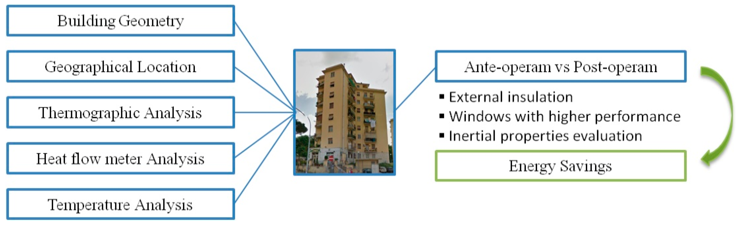
2. Methodology

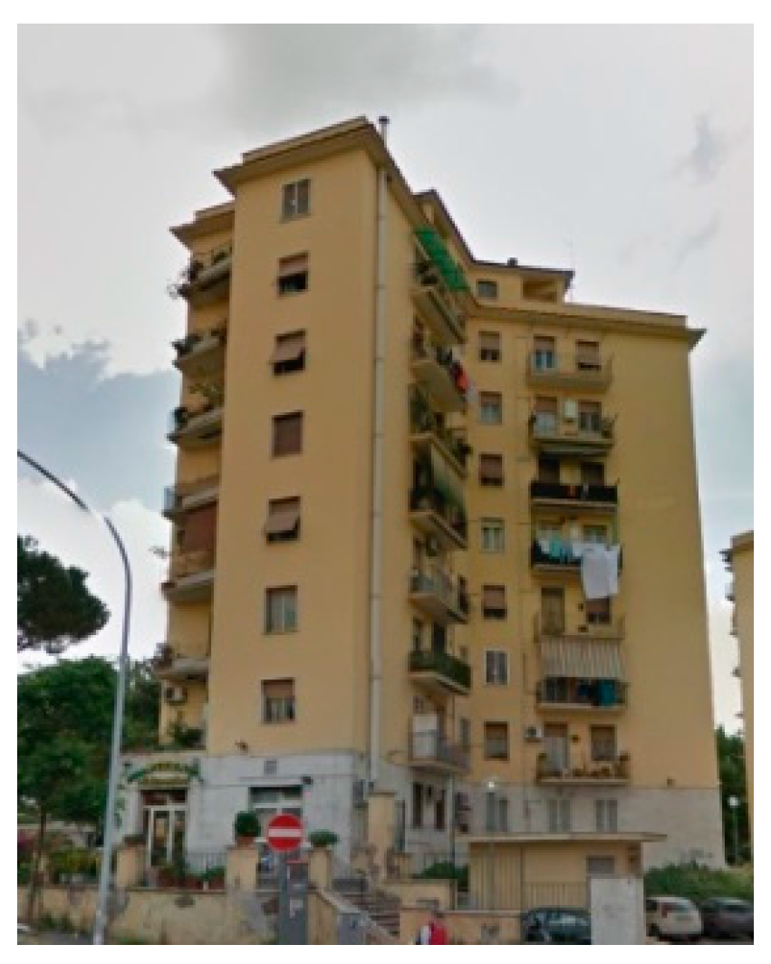
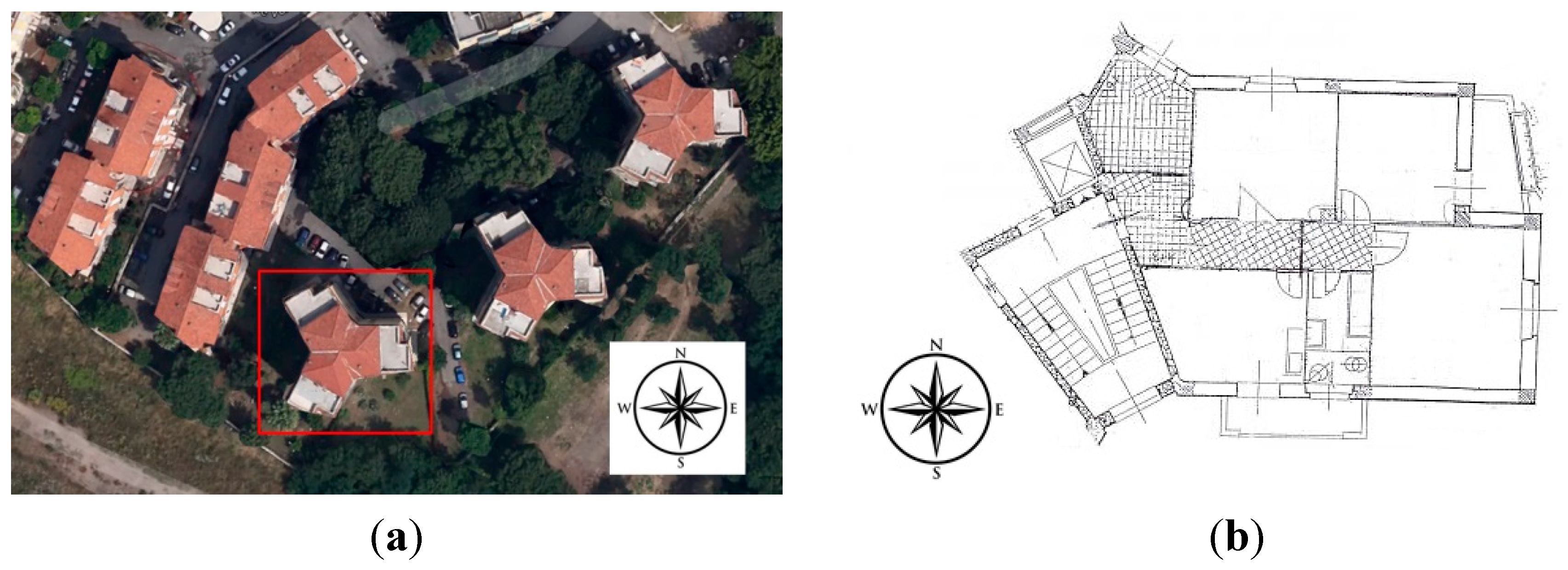
3. The Case Study
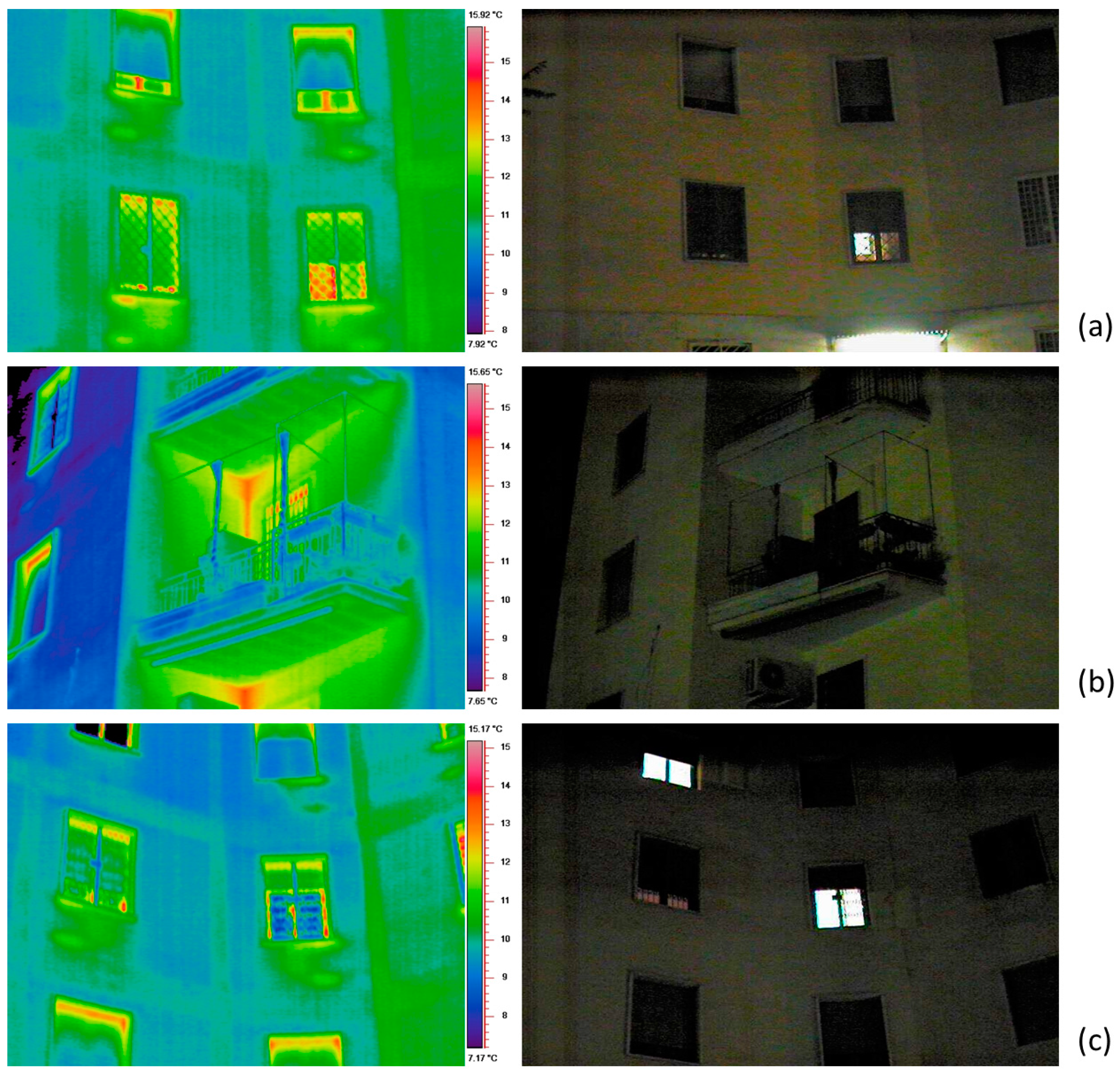
3.1. Building Characteristics


| Building’s characteristics | Values |
|---|---|
| Building Volume [m3] | 6984 |
| Building Total Surface [m2] | 2948.4 |
| Surface-Volume ratio | 0.42 |
| Opaque Surface Area [m2] | 2594.16 |
| Transparent Surface Area [m2] | 354.24 |
| Residential Units | 24 |
| Climatic Zone | D |
| Latitude | 41°54′39″24 N |
| Longitude | 12°28′54″48 E |


| Thermal Conductivity [W/mK] | Specific Heat Capacity [J/kgK] | Mass Density [kg/m3] | Thickness [m] | |
|---|---|---|---|---|
| Internal side | ||||
| Plasterboard | 0.350 | 840 | 1000 | 0.010 |
| Hollow Bricks | 0.589 | 840 | 700 | 0.370 |
| Concrete | 0.510 | 1000 | 1500 | 0.120 |
| Plasterboard | 0.350 | 840 | 1000 | 0.010 |
| External side | ||||
| Total Thickness | 0.51 | |||
| U-value | 0.918 W/m2K |
| Thermal Conductivity [W/mK] | Specific Heat Capacity [J/kgK] | Mass Density [kg/m3] | Thickness [m] | |
|---|---|---|---|---|
| Internal side | ||||
| Plasterboard | 0.350 | 840 | 1000 | 0.010 |
| Hollow Bricks | 0.589 | 840 | 700 | 0.240 |
| Cement Mortar | 1.250 | 1700 | 2000 | 0.050 |
| Waterproof Membrane | 0.220 | 840 | 343 | 0.005 |
| Cement Mortar | 1.250 | 1700 | 2000 | 0.050 |
| External side | ||||
| Total Thickness | 0.355 | |||
| U-value | 1.411 W/m2K |
| Thermal Transmittance [W/m2K] | g-value | |
|---|---|---|
| Frame | 2.27 | - |
| Single Glass 4 mm | 5.38 | 0.855 |

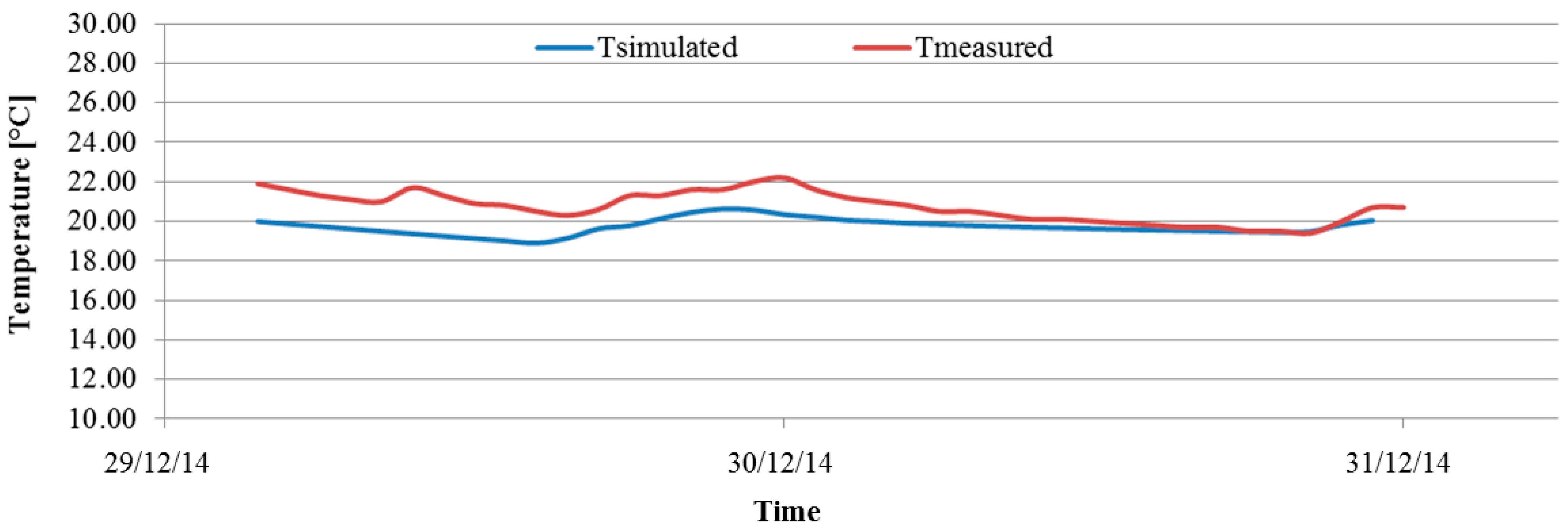
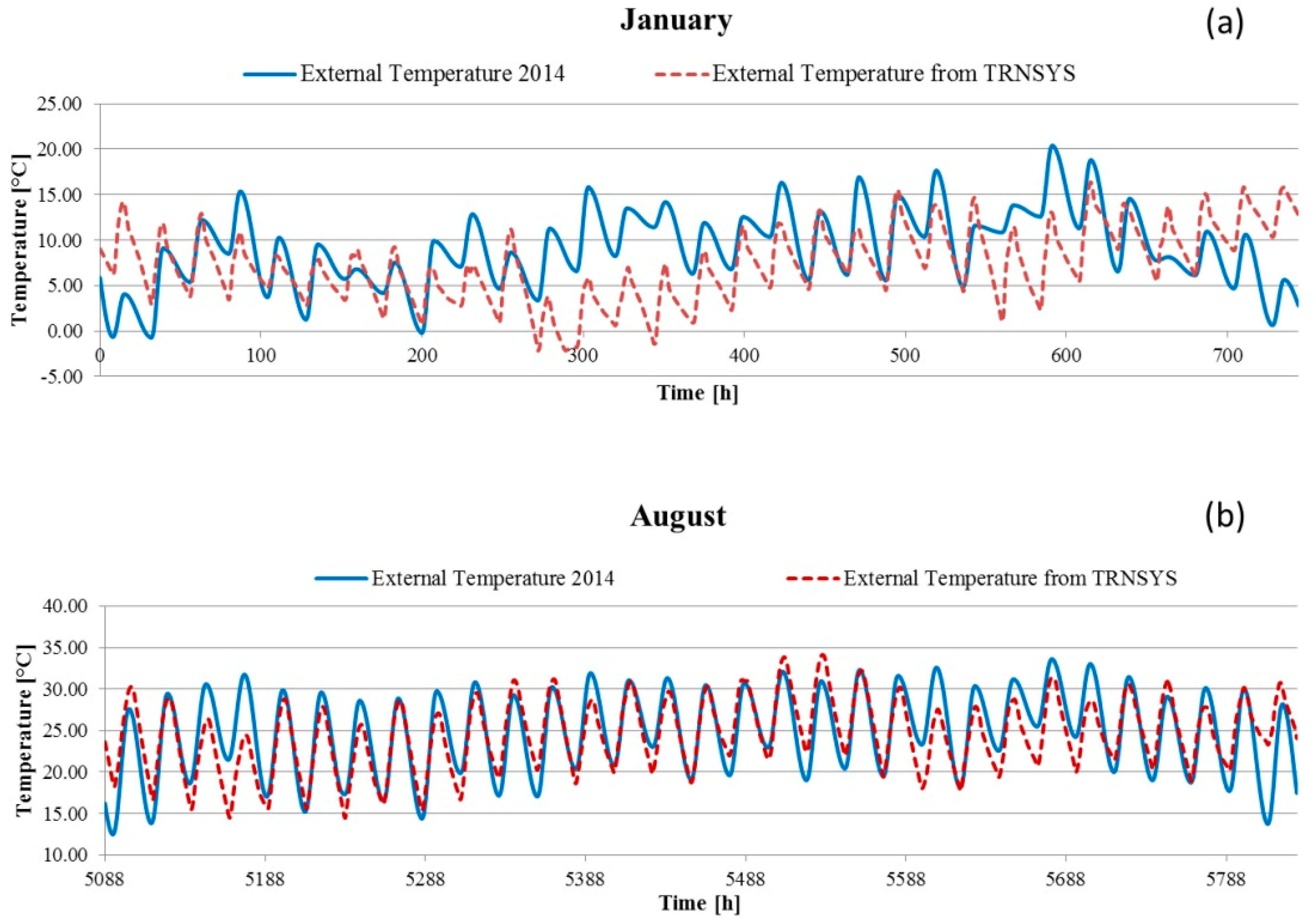
3.2. Building Modeling
| Walls | |
| Surface mass | 439 kg/m2 |
| Dynamic thermal transmittance | 0.157 W/m2K |
| Thermal attenuation | 0.172 |
| Thermal lag | 12.86 h |
| Roof | |
| Surface mass | 369.7 kg/m2 |
| Dynamic thermal transmittance | 0.507 W/m2K |
| Thermal attenuation | 0.344 |
| Thermal lag | 9.29 h |


3.3 Retrofit Strategies
| Structure [mm] | Thermal Transmittance [W/m2K] | g-value | Thermal Transmittance Limit (Climatic Zone D) | |
|---|---|---|---|---|
| Frame | - | 2.27 | - | - |
| Double Glaze-AIR | 4/16/4 | 2.83 | 0.755 | × |
| Double Glaze-ARGON | 4/16/4 | 1.40 | 0.589 | √ |
| Double Glaze-AIR (Low g) | 6/16/4 | 2.54 | 0.440 | × |
| Element | Thermal Transmittance [W/m2K] | Thermal Transmittance Limit (Climatic Zone D) |
|---|---|---|
| Insulated Roof – EPS 13 cm | 0.253 | √ |
| Wall - Coating 2 cm | 0.629 | × |
| Wall - Coating 4 cm | 0.478 | × |
| Wall - Coating 6 cm | 0.386 | × |
| Wall – Coating 8 cm | 0.324 | × |
| Wall – Coating 10 cm | 0.278 | √ |
| Base Case Walls | Wall-Coating 2 cm | Wall-Coating 4 cm | Wall-Coating 6 cm | Wall-Coating 8 cm | Wall-Coating 10 cm | |
|---|---|---|---|---|---|---|
| Surface mass | 439 kg/m2 | 439.5 kg/m2 | 440 kg/m2 | 440.5 kg/m2 | 441 kg/m2 | 441.5 kg/m2 |
| Dynamic thermal transmittance | 0.157 W/m2K | 0.044 W/m2K | 0.025 W/m2K | 0.018 W/m2K | 0.013 W/m2K | 0.011 W/m2K |
| Thermal attenuation | 0.172 | 0.070 | 0.052 | 0.045 | 0.042 | 0.039 |
| Thermal lag | 12.86 h | 14.41 h | 14.71 h | 14.9 h | 15.08 h | 15.28 h |
| Base Case Roof | Roof-13 cm EPS | |||||
| Surface mass | 369.7 kg/m2 | 372.9 kg/m2 | ||||
| Dynamic thermal transmittance | 0.507 W/m2K | 0.022 W/m2K | ||||
| Thermal attenuation | 0.344 | 0.085 | ||||
| Thermal lag | 9.29 h | 12.69 h |
4. Results and Discussion
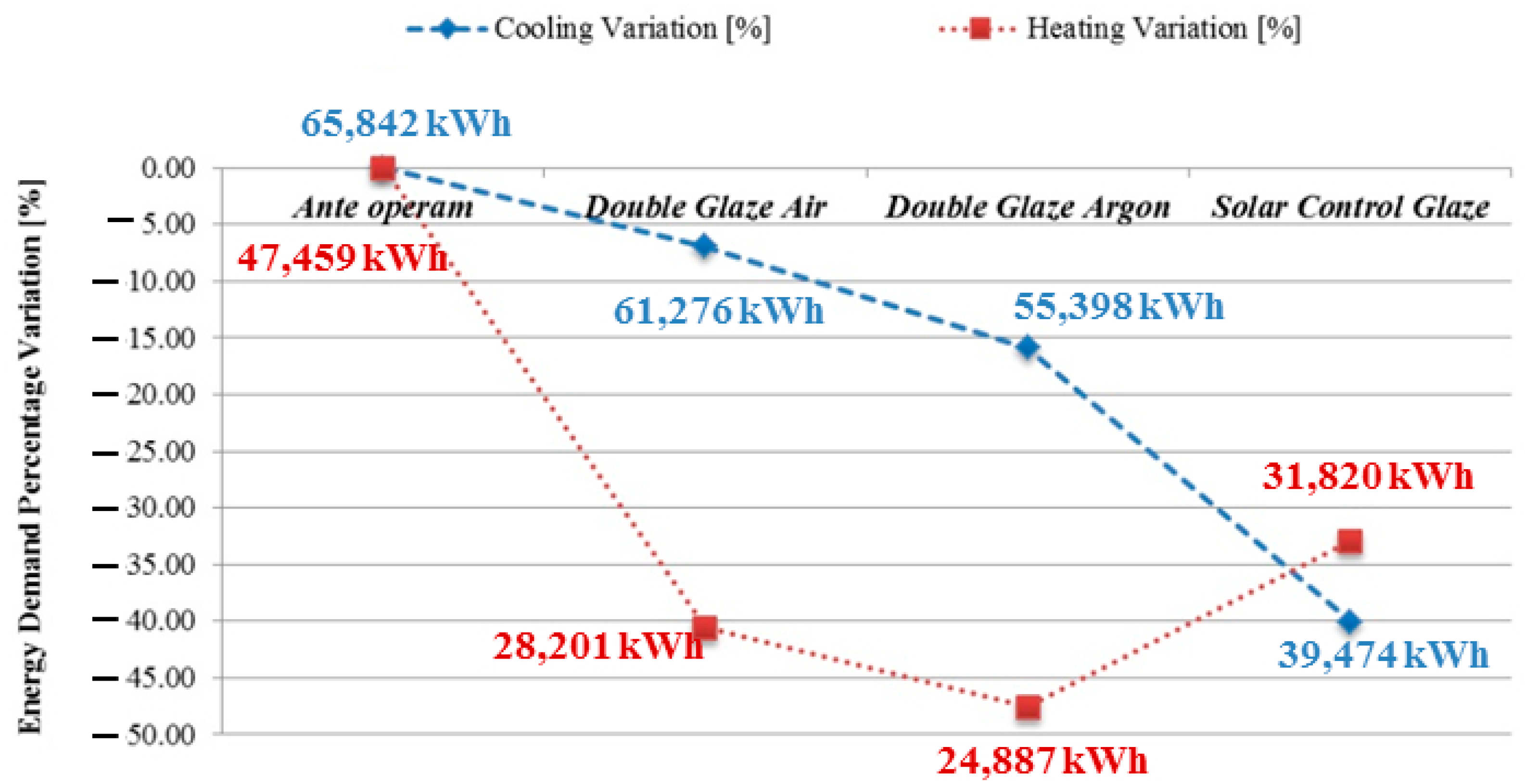
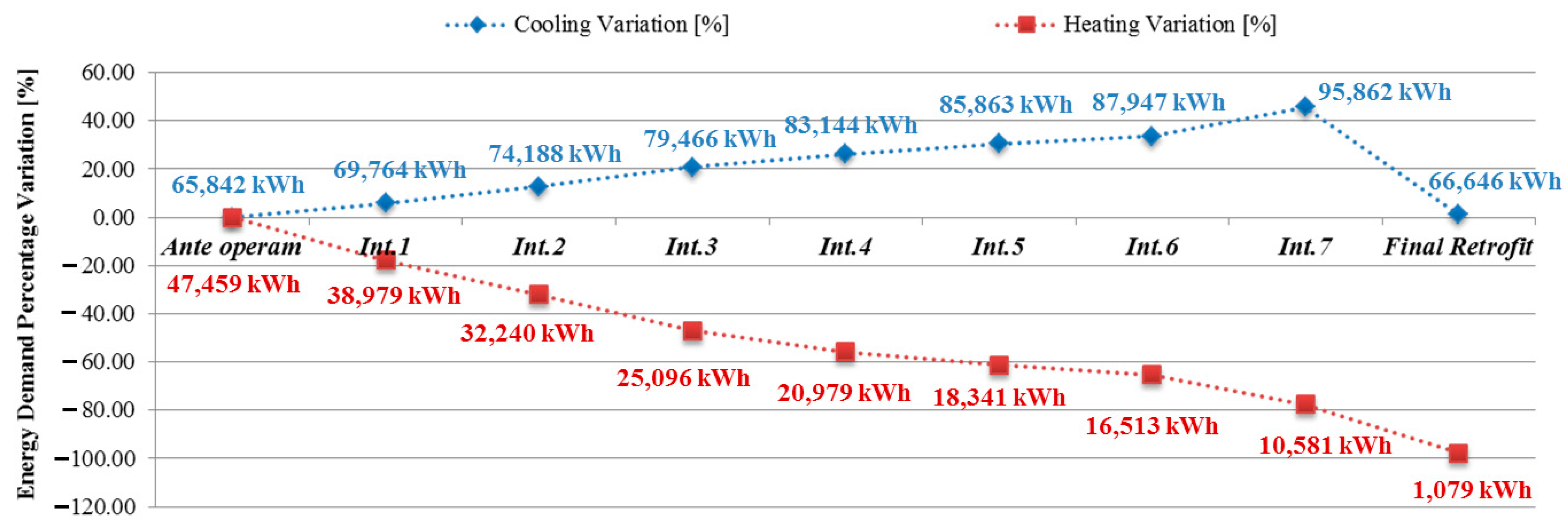
4.1. Retrofit Evaluation through Dynamic Simulations

| Name | Description |
|---|---|
| Ante Operam | Base case |
| Int. 1 | Insulated Roof—EPS 13 cm |
| Int. 2 | Wall—Coating 2 cm |
| Int. 3 | Wall—Coating 4 cm |
| Int. 4 | Wall—Coating 6 cm |
| Int. 5 | Wall—Coating 8 cm |
| Int. 6 | Wall—Coating 10 cm |
| Int. 7 | Wall (Coating 10 cm) + Roof (EPS 13 cm) |
| Final Retrofit | Wall (Coating 10 cm) + Roof (EPS 13 cm) + Double glaze with air (low g) |

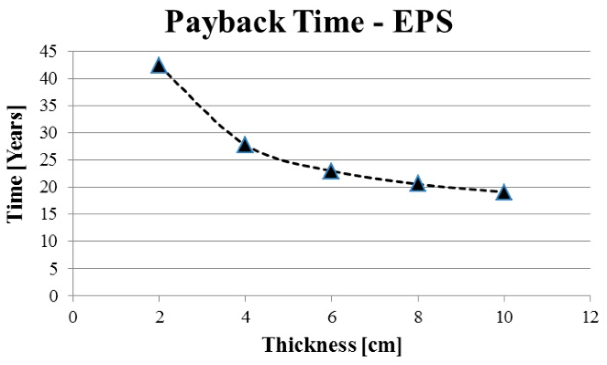
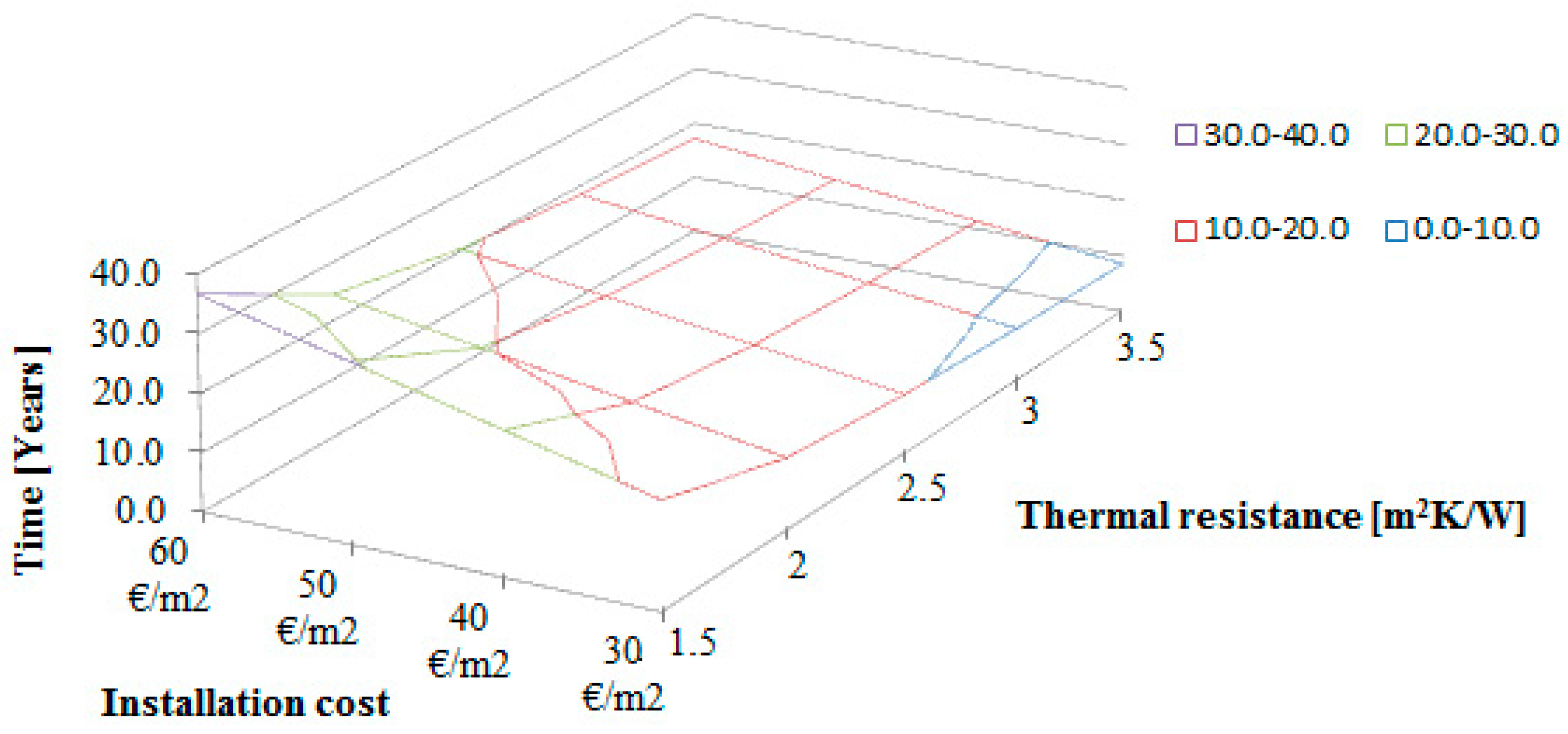
4.2. Payback Time


5. Conclusions
Author Contributions
Conflicts of Interest
References
- Salata, F.; de Lieto Vollaro, A.; Ferraro, A. An economic perspective on the reliability of lighting systems in building with highly efficient energy: A case study. Energy Convers. Manag. 2014, 84, 623–632. [Google Scholar] [CrossRef]
- Salata, F.; de Lieto Vollaro, A.; de Lieto Vollaro, R. A case study of technical and economic comparison among energy production systems in a complex of historic buildings in Rome. Energy Procedia 2014, 45, 482–491. [Google Scholar] [CrossRef]
- Salata, F.; de Lieto Vollaro, A.; de Lieto Vollaro, R.; Mancieri, L. Method for energy optimization with reliability analysis of a trigeneration and teleheating system on urban scale: A case study. Energy Build. 2015, 86, 118–136. [Google Scholar] [CrossRef]
- Ascione, F.; Bianco, N.; de Masi, R.F.; de’Rossi, F.; Vanoli, G.P. Energy retrofit of an educational building in the ancient center of Benevento. Feasibility study of energy savings and respect of the historical value. Energy Build. 2015, 95, 172–183. [Google Scholar] [CrossRef]
- Pisello, A.L.; Rossi, F.; Cotana, F. Summer and winter effect of innovative cool roof tiles on the dynamic thermal behavior of buildings. Energies 2014, 7, 2343–2361. [Google Scholar] [CrossRef]
- Friedman, C.; Becker, N.; Erell, E. Energy retrofit of residential building envelopes in Israel: A cost benefit analysis. Energy 2014, 77, 183–193. [Google Scholar] [CrossRef]
- Evangelisti, L.; Battista, G.; Guattari, C.; Basilicata, C.; de Lieto Vollaro, R. Influence of the thermal inertia in the European simplified procedures for the assessment of buildings’ energy performance. Sustainability 2014, 6, 4514–4524. [Google Scholar] [CrossRef]
- Foucquier, A.; Robert, S.; Suard, F.; Stéphan, L.; Jay, A. State of the art in building modelling and energy performances prediction: A review. Renew. Sustain. Energy Rev. 2013, 23, 272–288. [Google Scholar] [CrossRef]
- Fumo, N. A review on the basics of building energy estimation. Renew. Sustain. Energy Rev. 2014, 31, 53–60. [Google Scholar] [CrossRef]
- Baldinelli, G.; Asdrubali, F.; Baldassarri, C.; Bianchi, F.; D’Alessandro, F.; Schiavoni, S.; Basilicata, C. Energy and environmental performance optimization of a wooden window: A holistic approach. Energy Build. 2014, 79, 114–131. [Google Scholar] [CrossRef]
- Baldinelli, G.; Bianchi, F. Windows thermal resistance: Infrared thermography aided comparative analysis among finite volumes simulations and experimental methods. Appl. Energy 2014, 136, 250–258. [Google Scholar] [CrossRef]
- Asdrubali, F.; D’Alessandro, F.; Schiavoni, S. A review of unconventional sustainable building insulation materials. Sustain. Mater. Technol. 2015, 4, 1–17. [Google Scholar] [CrossRef]
- Peruzzi, L.; Salata, F.; de Lieto Vollaro, A.; de Lieto Vollaro, R. The reliability of technological systems with high energy efficiency in residential buildings. Energy Build. 2014, 68, 19–24. [Google Scholar] [CrossRef]
- ISO. Thermal Insulation—Building Elements—In-Situ Measurement of Thermal Resistance and Thermal Transmittance; ISO 9869–1; ISO: Geneva, Switzerland, 2014. [Google Scholar]
- Asdrubali, F.; D’Alessandro, F.; Baldinelli, G.; Bianchi, F. Evaluating in situ thermal transmittance of green buildings masonries—A case study. Case Stud. Constr. Mater. 2014, 1, 53–59. [Google Scholar] [CrossRef]
- De Lieto Vollaro, R.; Guattari, C.; Evangelisti, L.; Battista, G.; Carnielo, E.; Gori, P. Building energy performance analysis: A case study. Energy Build. 2015, 87, 87–94. [Google Scholar] [CrossRef]
- Asdrubali, F.; Baldinelli, G.; Bianchi, F.; Sambuco, S. A comparison between environmental sustainability rating systems LEED and ITACA for residential buildings. Build. Environ. 2015, 86, 98–108. [Google Scholar] [CrossRef]
- Evangelisti, L.; Battista, G.; Guattari, C.; Basilicata, C.; de Lieto Vollaro, R. Analysis of two models for evaluating energy performance of different buildings. Sustainability 2014, 6, 5311–5321. [Google Scholar] [CrossRef]
- De Lieto Vollaro, R.; Evangelisti, L.; Carnielo, E.; Battista, G.; Gori, P.; Guattari, C.; Fanchiotti, A. An Integrated Approach for an Historical Buildings Energy Analysis in a Smart Cities Perspective. Energy Procedia 2014, 45, 372–378. [Google Scholar] [CrossRef]
- TRNSYS. A Transient Systems Simulation Program. Available online: http://sel.me.wisc.edu/trnsys (accessed on 7 January 2015).
- Mitalas, G.P. Transfer function method of calculating cooling loads, heat extraction and space temperature. ASHRAE J. 1973, 14, 54–56. [Google Scholar] [CrossRef]
- De Lieto Vollaro, R.; Evangelisti, L.; Battista, G.; Gori, P.; Guattari, C.; Fanchiotti, A. Bus for urban public transport: Energy performance optimization. Energy Procedia 2014, 48, 731–738. [Google Scholar] [CrossRef]
- De Lieto Vollaro, R.; Calvesi, M.; Battista, G.; Evangelisti, L.; Botta, F. Calculation model for optimization design of the low impact energy systems for the buildings. Energy Procedia 2014, 48, 1459–1467. [Google Scholar] [CrossRef]
- Battista, G.; Evangelisti, L.; Guattari, C.; Basilicata, C.; de Lieto Vollaro, R. Buildings energy efficiency: Interventions analysis under a smart cities approach. Sustainability 2014, 6, 4694–4705. [Google Scholar] [CrossRef]
- Lam, K.P.; Zhao1, J.; Ydstie, E.B.; Wirick, J.; Qi, M.; Park, J. An energy plus whole building energy model calibration method for office buildings using occupant behavior data mining and empirical data. In Proceedings of the 2014 ASHRAE/IBPSA-USA Building Simulation Conference, Atlanta, GA, USA, 10–12 September 2014.
- American Society of Heating, Refrigerating and Air Conditioning Engineers. Guideline 14-2002: Measurement of Energy and Demand Savings; ASHRAE: Atlanta, GA, USA, 2002. [Google Scholar]
- Moncef, K. Weatherization and Energy Efficiency Improvement for Existing Homes: An Engineering Approach; CRC Press: Boca Raton, FL, USA, 2012; pp. 133–134. [Google Scholar]
- TESTO 435–2—Strumento multifunzione. Available online: http://www.testo.it/dettagli_prodotto/0563+4352/testo-435-2-Strumento-multifunzione (accessed on 7 January 15).
- UNI TS 11300–1, Determination of the Buildings Energy Demand for the Air-Conditioning in Summer and Winter. Available online: www.uni.com (assessed on 28 July 2015). (In Italian)
- Ministry of Economic Development. Available online: http://www.sviluppoeconomico.gov.it/ (assessed on 28 July 2015). (In Italian)
- Masoso, O.T.; Grobler, L.J. A new and innovative look at anti-insulation behaviour in building energy consumption. Energy Build. 2008, 40, 1889–1894. [Google Scholar] [CrossRef]
© 2015 by the authors; licensee MDPI, Basel, Switzerland. This article is an open access article distributed under the terms and conditions of the Creative Commons Attribution license (http://creativecommons.org/licenses/by/4.0/).
Share and Cite
Evangelisti, L.; Guattari, C.; Gori, P. Energy Retrofit Strategies for Residential Building Envelopes: An Italian Case Study of an Early-50s Building. Sustainability 2015, 7, 10445-10460. https://doi.org/10.3390/su70810445
Evangelisti L, Guattari C, Gori P. Energy Retrofit Strategies for Residential Building Envelopes: An Italian Case Study of an Early-50s Building. Sustainability. 2015; 7(8):10445-10460. https://doi.org/10.3390/su70810445
Chicago/Turabian StyleEvangelisti, Luca, Claudia Guattari, and Paola Gori. 2015. "Energy Retrofit Strategies for Residential Building Envelopes: An Italian Case Study of an Early-50s Building" Sustainability 7, no. 8: 10445-10460. https://doi.org/10.3390/su70810445