An Accurate Method to Correct Atmospheric Phase Delay for InSAR with the ERA5 Global Atmospheric Model


Abstract
:
1. Introduction
2. Methodology
2.1. Traditional Methods Based on GAM
2.2. Drawbacks of the ZTD Approach
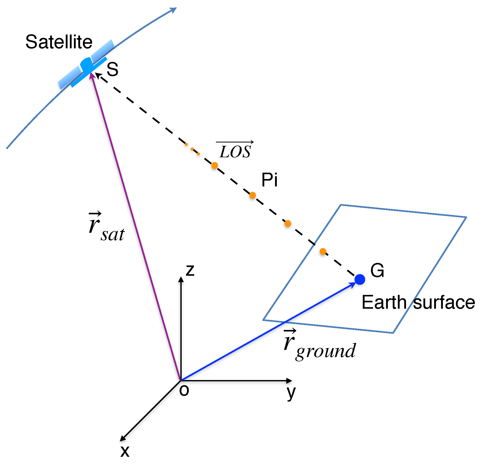
2.3. Precise LOS Phase Delay Calculation
3. Test Sites, Datasets, and SAR Data Processing
3.1. Tenerife Island, Spain
3.2. Crete, Greece
3.3. Almería, Spain
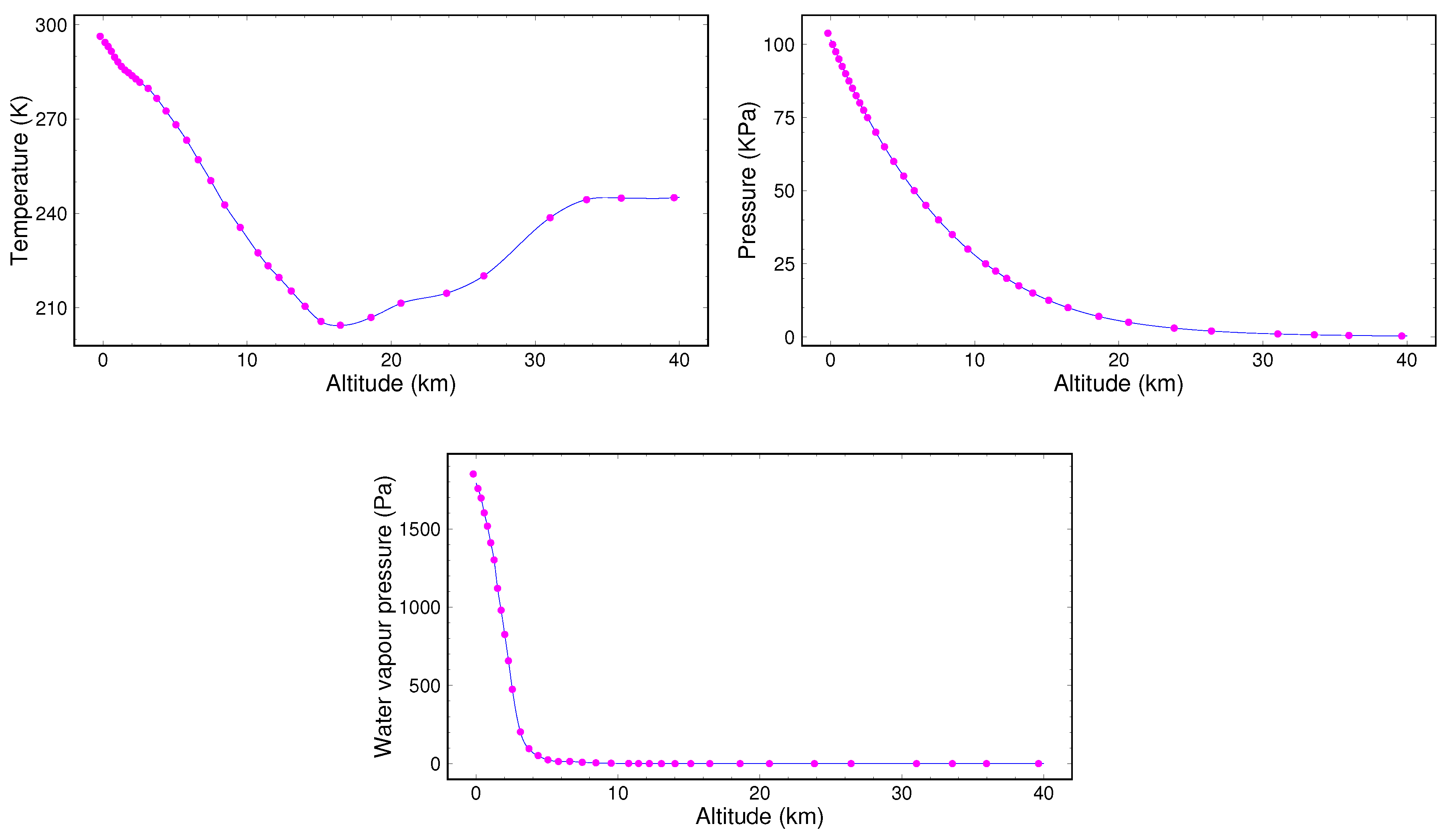
3.4. European Center for Medium-Range Weather Forecasts (ECMWF) Datasets
3.5. SAR Datasets and Data Processing
4. Algorithm Validation in Tenerife Island
4.1. Implementation of the Improved Method
4.2. Case Study Discussion of Tenerife Island, Spain
4.3. Statistical Analyses Discussion
5. Applications to Different Sites
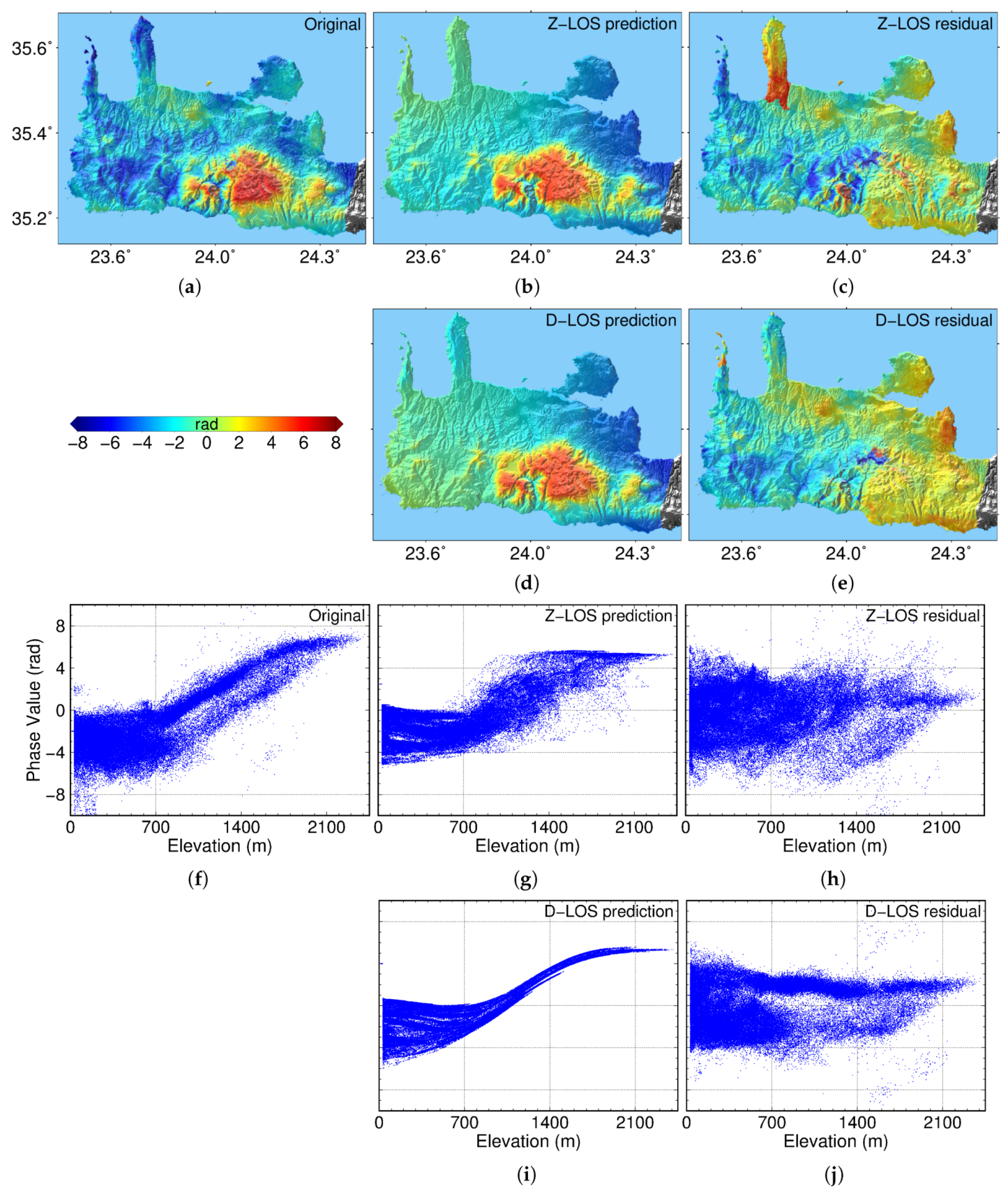
5.1. Results and Discussion in Crete, Greece
5.2. Results and Discussion in Almería, Spain
6. Discussion
7. Conclusions
Author Contributions
Funding
Acknowledgments
Conflicts of Interest
References
- Wright, T.J.; Lu, Z.; Wicks, C. Source model for the Mw 6.7, 23 October 2002, Nenana Mountain Earthquake (Alaska) from InSAR. Geophys. Res. Lett. 2003, 30, 1974. [Google Scholar] [CrossRef]
- Delouis, B.; Nocquet, J.M.; Vallée, M. Slip distribution of the February 27, 2010 Mw = 8.8 Maule earthquake, central Chile, from static and high-rate GPS, InSAR, and broadband teleseismic data. Geophys. Res. Lett. 2010, 37, L17305. [Google Scholar] [CrossRef]
- Polcari, M.; Montuori, A.; Bignami, C.; Moro, M.; Stramondo, S.; Tolomei, C. Using multi-band InSAR data for detecting local deformation phenomena induced by the 2016–2017 Central Italy seismic sequence. Remote Sens. Environ. 2017, 201, 234–242. [Google Scholar] [CrossRef]
- Cavalié, O.; Lasserre, C.; Doin, M.P.; Peltzer, G.; Sun, J.; Xu, X.; Shen, Z.K. Measurement of interseismic strain across the Haiyuan fault (Gansu, China), by InSAR. Earth Planet. Sci. Lett. 2008, 275, 246–257. [Google Scholar] [CrossRef]
- Biggs, J.; Amelung, F.; Gourmelen, N.; Dixon, T.H.; Kim, S.W. InSAR observations of 2007 Tanzania rifting episode reveal mixed fault and dyke extension in an immature continental rift. Geophys. J. Int. 2009, 179, 549–558. [Google Scholar] [CrossRef] [Green Version]
- Lu, Z.; Freymueller, J.T. Synthetic aperture radar interferometry coherence analysis over Katmai volcano group, Alaska. J. Geophys. Res. Solid Earth 1998, 103, 29887–29894. [Google Scholar] [CrossRef]
- Chaussard, E.; Amelung, F.; Aoki, Y. Characterization of open and closed volcanic systems in Indonesia and Mexico using InSAR time series. J. Geophys. Res. Solid Earth 2013, 118, 3957–3969. [Google Scholar] [CrossRef]
- Massonnet, D.; Briole, P.; Arnaud, A. Deflation of Mount Etna monitored by spaceborne radar interferometry. Nature 1995, 375, 567–570. [Google Scholar] [CrossRef]
- Singleton, A.; Li, Z.; Hoey, T.; Muller, J.P. Evaluating sub-pixel offset techniques as an alternative to D-InSAR for monitoring episodic landslide movements in vegetated terrain. Remote Sens. Environ. 2014, 147, 133–144. [Google Scholar] [CrossRef] [Green Version]
- Massonnet, D.; Feigl, K.L. Radar interferometry and its application to changes in the Earth’s surface. Rev. Geophys. 1998, 36, 441–500. [Google Scholar] [CrossRef]
- Amelung, F.; Galloway, D.L.; Bell, J.W.; Zebker, H.A.; Laczniak, R.J. Sensing the ups and downs of Las Vegas: InSAR reveals structural control of land subsidence and aquifer-system deformation. Geology 1999, 27, 483–486. [Google Scholar] [CrossRef]
- Chaussard, E.; Wdowinski, S.; Cabral-Cano, E.; Amelung, F. Land subsidence in central Mexico detected by ALOS InSAR time-series. Remote Sens. Environ. 2014, 140, 94–106. [Google Scholar] [CrossRef]
- Rucci, A.; Ferretti, A.; Guarnieri, A.M.; Rocca, F. Sentinel 1 SAR interferometry applications: The outlook for sub millimeter measurements. Remote Sens. Environ. 2012, 120, 156–163. [Google Scholar] [CrossRef]
- Ferretti, A.; Colombo, D.; Fumagalli, A.; Novali, F.; Rucci, A. InSAR data for monitoring land subsidence: Time to think big. Proc. Int. Assoc. Hydrol. Sci. 2015, 372, 331. [Google Scholar] [CrossRef]
- Spaans, K.; Hooper, A. InSAR processing for volcano monitoring and other near-real time applications. J. Geophys. Res. Solid Earth 2016, 121, 2947–2960. [Google Scholar] [CrossRef] [Green Version]
- Goldstein, R. Atmospheric limitations to repeat-track radar interferometry. Geophys. Res. Lett. 1995, 22, 2517–2520. [Google Scholar] [CrossRef] [Green Version]
- Zebker, H.A.; Rosen, P.A.; Hensley, S. Atmospheric effects in interferometric synthetic aperture radar surface deformation and topographic maps. J. Geophys. Res. Solid Earth 1997, 102, 7547–7563. [Google Scholar] [CrossRef]
- Hanssen, R.F. Radar Interferometry: Data Interpretation and Error Analysis; Springer Science & Business Media: Berlin/Heidelberg, Germany, 2001; Volume 2. [Google Scholar]
- Ferretti, A.; Prati, C.; Rocca, F. Permanent scatterers in SAR interferometry. IEEE Trans. Geosci. Remote Sens. 2001, 39, 8–20. [Google Scholar] [CrossRef]
- Berardino, P.; Fornaro, G.; Lanari, R.; Sansosti, E. A new algorithm for surface deformation monitoring based on small baseline differential SAR interferograms. IEEE Trans. Geosci. Remote Sens. 2002, 40, 2375–2383. [Google Scholar] [CrossRef] [Green Version]
- Lanari, R.; Mora, O.; Manunta, M.; Mallorquí, J.J.; Berardino, P.; Sansosti, E. A small-baseline approach for investigating deformations on full-resolution differential SAR interferograms. IEEE Trans. Geosci. Remote Sens. 2004, 42, 1377–1386. [Google Scholar] [CrossRef]
- Blanco-Sanchez, P.; Mallorquí, J.J.; Duque, S.; Monells, D. The coherent pixels technique (CPT): An advanced DInSAR technique for nonlinear deformation monitoring. Pure Appl. Geophys. 2008, 165, 1167–1193. [Google Scholar] [CrossRef]
- Liu, S. Satellite Radar Interferometry: Estimation of Atmospheric Delay. Ph.D. Thesis, TU Delft, Delft University of Technology, Delft, The Netherlands, 2012. [Google Scholar]
- Gong, W.; Meyer, F.J.; Liu, S.; Hanssen, R.F. Temporal filtering of InSAR data using statistical parameters from NWP models. IEEE Trans. Geosci. Remote Sens. 2015, 53, 4033–4044. [Google Scholar] [CrossRef]
- Knospe, S.H.; Jonsson, S. Covariance estimation for dInSAR surface deformation measurements in the presence of anisotropic atmospheric noise. IEEE Trans. Geosci. Remote Sens. 2010, 48, 2057–2065. [Google Scholar] [CrossRef]
- Beauducel, F.; Briole, P.; Froger, J.L. Volcano-wide fringes in ERS synthetic aperture radar interferograms of Etna (1992–1998): Deformation or tropospheric effect? J. Geophys. Res. Solid Earth 2000, 105, 16391–16402. [Google Scholar] [CrossRef]
- Cavalié, O.; Doin, M.P.; Lasserre, C.; Briole, P. Ground motion measurement in the Lake Mead area, Nevada, by differential synthetic aperture radar interferometry time series analysis: Probing the lithosphere rheological structure. J. Geophys. Res. Solid Earth 2007, 112, B03403. [Google Scholar] [CrossRef]
- Elliott, J.; Biggs, J.; Parsons, B.; Wright, T. InSAR slip rate determination on the Altyn Tagh Fault, northern Tibet, in the presence of topographically correlated atmospheric delays. Geophys. Res. Lett. 2008, 35, L12309. [Google Scholar] [CrossRef]
- Doin, M.P.; Lasserre, C.; Peltzer, G.; Cavalié, O.; Doubre, C. Corrections of stratified tropospheric delays in SAR interferometry: Validation with global atmospheric models. J. Appl. Geophys. 2009, 69, 35–50. [Google Scholar] [CrossRef]
- Lin, Y.n.N.; Simons, M.; Hetland, E.A.; Muse, P.; DiCaprio, C. A multiscale approach to estimating topographically correlated propagation delays in radar interferograms. Geochem. Geophys. Geosyst. 2010, 11, Q09002. [Google Scholar] [CrossRef]
- Bekaert, D.; Hooper, A.; Wright, T. A spatially variable power law tropospheric correction technique for InSAR data. J. Geophys. Res. Solid Earth 2015, 120, 1345–1356. [Google Scholar] [CrossRef]
- Hu, Z.; Mallorquí, J.J.; Fan, H. Atmospheric artifacts correction with a covariance-weighted linear model over mountainous regions. IEEE Trans. Geosci. Remote Sens. 2018, 56, 6995–7008. [Google Scholar] [CrossRef]
- Williams, S.; Bock, Y.; Fang, P. Integrated satellite interferometry: Tropospheric noise, GPS estimates and implications for interferometric synthetic aperture radar products. J. Geophys. Res. 1998, 103, 27051–27067. [Google Scholar] [CrossRef]
- Onn, F.; Zebker, H. Correction for interferometric synthetic aperture radar atmospheric phase artifacts using time series of zenith wet delay observations from a GPS network. J. Geophys. Res. Solid Earth 2006, 111, B09102. [Google Scholar] [CrossRef]
- Löfgren, J.S.; Björndahl, F.; Moore, A.W.; Webb, F.H.; Fielding, E.J.; Fishbein, E.F. Tropospheric correction for InSAR using interpolated ECMWF data and GPS zenith total delay from the Southern California integrated GPS network. In Proceedings of the 2010 IEEE International Geoscience and Remote Sensing Symposium, Honolulu, HI, USA, 25–30 July 2010; pp. 4503–4506. [Google Scholar]
- Yu, C.; Penna, N.T.; Li, Z. Generation of real-time mode high-resolution water vapor fields from GPS observations. J. Geophys. Res. Atmos. 2017, 122, 2008–2025. [Google Scholar] [CrossRef]
- Li, Z.; Fielding, E.J.; Cross, P.; Muller, J.P. Interferometric synthetic aperture radar atmospheric correction: Medium resolution imaging spectrometer and advanced synthetic aperture radar integration. Geophys. Res. Lett. 2006, 33, L06816. [Google Scholar] [CrossRef]
- Li, Z.; Muller, J.P.; Cross, P.; Albert, P.; Fischer, J.; Bennartz, R. Assessment of the potential of MERIS near-infrared water vapor products to correct ASAR interferometric measurements. Int. J. Remote Sens. 2006, 27, 349–365. [Google Scholar] [CrossRef]
- Delacourt, C.; Briole, P.; Achache, J. Tropospheric corrections of SAR interferograms with strong topography. Application to Etna. Geophys. Res. Lett. 1998, 25, 2849–2852. [Google Scholar] [CrossRef]
- Foster, J.; Brooks, B.; Cherubini, T.; Shacat, C.; Businger, S.; Werner, C. Mitigating atmospheric noise for InSAR using a high resolution weather model. Geophys. Res. Lett. 2006, 33, L16304. [Google Scholar] [CrossRef]
- Cong, X.; Balss, U.; Eineder, M.; Fritz, T. Imaging geodesy—Centimeter-level ranging accuracy with TerraSAR-X: An update. IEEE Geosci. Remote Sens. Lett. 2012, 9, 948–952. [Google Scholar] [CrossRef]
- Cong, X. SAR Interferometry for Volcano Monitoring: 3D-PSI Analysis and Mitigation of Atmospheric Refractivity. Ph.D. Thesis, Technische Universität München, München, Germany, 2014. [Google Scholar]
- Jolivet, R.; Agram, P.S.; Lin, N.Y.; Simons, M.; Doin, M.P.; Peltzer, G.; Li, Z. Improving InSAR geodesy using global atmospheric models. J. Geophys. Res. Solid Earth 2014, 119, 2324–2341. [Google Scholar] [CrossRef]
- Yu, C.; Li, Z.; Penna, N.T. Interferometric synthetic aperture radar atmospheric correction using a GPS-based iterative tropospheric decomposition model. Remote Sens. Environ. 2018, 204, 109–121. [Google Scholar] [CrossRef]
- Hersbach, H.; Dee, D. ERA5 reanalysis is in production. ECMWF Newslett. 2016, 147, 5–6. [Google Scholar]
- Jolivet, R.; Grandin, R.; Lasserre, C.; Doin, M.P.; Peltzer, G. Systematic InSAR tropospheric phase delay corrections from global meteorological reanalysis data. Geophys. Res. Lett. 2011, 38, L17311. [Google Scholar] [CrossRef]
- Cong, X.; Balss, U.; Rodriguez Gonzalez, F.; Eineder, M. Mitigation of Tropospheric Delay in SAR and InSAR Using NWP Data: Its Validation and Application Examples. Remote Sens. 2018, 10, 1515. [Google Scholar] [CrossRef]
- Bekaert, D.; Walters, R.; Wright, T.; Hooper, A.; Parker, D. Statistical comparison of InSAR tropospheric correction techniques. Remote Sens. Environ. 2015, 170, 40–47. [Google Scholar] [CrossRef] [Green Version]
- Yu, C.; Li, Z.; Penna, N.T.; Crippa, P. Generic atmospheric correction model for Interferometric Synthetic Aperture Radar observations. J. Geophys. Res. Solid Earth 2018, 123, 9202–9222. [Google Scholar] [CrossRef]
- Smith, E.K.; Weintraub, S. The constants in the equation for atmospheric refractive index at radio frequencies. Proc. IRE 1953, 41, 1035–1037. [Google Scholar] [CrossRef]
- Perissin, D.; Pichelli, E.; Ferretti, R.; Rocca, F.; Pierdicca, N. The MM5 numerical model to correct PSInSAR atmospheric phase screen. In Proceedings of the FRINGE, Frascati, Italy, 30 November–4 December 2009. [Google Scholar]
- SUHET. Sentinel-1 User Handbook; European Space Agency: Paris, France, 2013. Available online: https: //sentinel.esa.int/.
- Solana, M. Evaluación de la Peligrosidad Volcánica en Tenerife a Partir de la Reconstrucción de Cuatro Erupciones Históricas. Ph.D. Thesis, Universidad Complutense de Madrid, Madrid, Spain, 1998. [Google Scholar]
- Fernández, J.; Yu, T.T.; Rodrıguez-Velasco, G.; González-Matesanz, J.; Romero, R.; Rodrıguez, G.; Quirós, R.; Dalda, A.; Aparicio, A.; Blanco, M. New geodetic monitoring system in the volcanic island of Tenerife, Canaries, Spain. Combination of InSAR and GPS techniques. J. Volcanol. Geotherm. Res. 2003, 124, 241–253. [Google Scholar] [CrossRef]
- Fernández, J.; Romero, R.; Carrasco, D.; Tiampo, K.F.; Rodríguez-Velasco, G.; Aparicio, A.; Araña, V.; González-Matesanz, F. Detection of displacements on Tenerife Island, Canaries, using radar interferometry. Geophys. J. Int. 2005, 160, 33–45. [Google Scholar] [CrossRef]
- Fernández, J.; Tizzani, P.; Manzo, M.; Borgia, A.; González, P.; Martí, J.; Pepe, A.; Camacho, A.; Casu, F.; Berardino, P.; et al. Gravity-driven deformation of Tenerife measured by InSAR time series analysis. Geophys. Res. Lett. 2009, 36, L04306. [Google Scholar] [CrossRef]
- Eff-Darwich, A.; Pérez, J.C.; Fernández, J.; García-Lorenzo, B.; González, A.; González, P.J. Using a mesoscale meteorological model to reduce the effect of tropospheric water vapor from DInSAR data: A case study for the island of Tenerife, Canary Islands. Pure Appl. Geophys. 2012, 169, 1425–1441. [Google Scholar] [CrossRef]
- Skamarock, W.C.; Klemp, J.B.; Dudhia, J.; Gill, D.O.; Barker, D.M.; Wang, W.; Powers, J.G. A Description of the Advanced Research WRF Version 3; NCAR Technical note-475+ STR; Mesoscale and Microscale Meteorology Division, NCAR: Boulder, CO, USA, 2008. [Google Scholar]
- Rieger, S. Regional-Scale, Natural Persistent Scatterer Interferometry, Island of Crete (Greece), and Comparison to Vertical Surface Deformation on the Millennial-, and Million-Year Time-Scales. Ph.D. Thesis, LMU, München, Germany, 2015. [Google Scholar]
- Adam, N. Algorithmic PSI Improvement in Mountainous Areas by Atmosphere Mitigation; Terrafirma (ESA) Technical Note; 2013. [Google Scholar]
- Pulido-Bosch, A.; Delgado, J.; Sola, F.; Vallejos, Á.; Vicente, F.; López-Sánchez, J.M.; Mallorquí, J.J. Identification of potential subsidence related to pumping in the Almería basin (SE Spain). Hydrol. Processes 2012, 26, 731–740. [Google Scholar] [CrossRef]
- Chen, C.W.; Zebker, H.A. Phase unwrapping for large SAR interferograms: Statistical segmentation and generalized network models. IEEE Trans. Geosci. Remote Sens. 2002, 40, 1709–1719. [Google Scholar] [CrossRef]


| Ifg. No. | SLC1 | SLC2 | Baseline | Phase SD | ||
|---|---|---|---|---|---|---|
| Original | Z-LOS Residual | D-LOS Residual | ||||
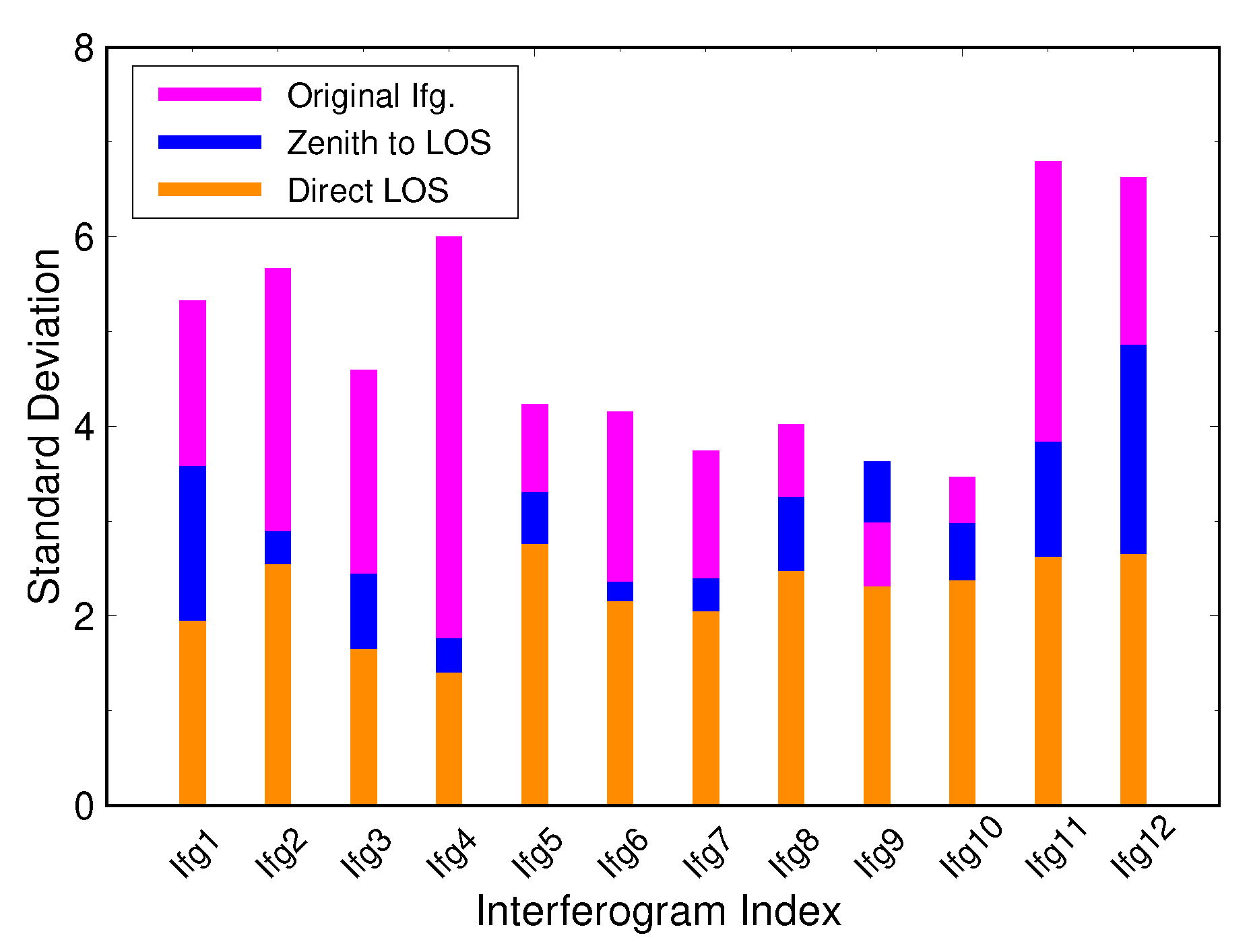
| Ifg1 | 25/09/2015 | 07/10/2015 | 18.2 m | 5.32 | 3.57 (33%) | 1.94 (64%) |
| Ifg2 | 07/10/2015 | 12/11/2015 | −29.7 m | 5.66 | 2.89 (49%) | 2.54 (55%) |
| Ifg3 | 12/11/2015 | 18/12/2015 | 20.5 m | 4.59 | 2.44 (47%) | 1.65 (64%) |
| Ifg4 | 06/12/2015 | 11/01/2016 | −14.1 m | 5.99 | 1.75 (71%) | 1.40 (77%) |
| Ifg5 | 23/01/2016 | 04/02/2016 | 10.6 m | 4.23 | 3.30 (22%) | 2.75 (35%) |
| Ifg6 | 28/02/2016 | 11/03/2016 | 20.0 m | 4.15 | 2.36 (43%) | 2.14 (48%) |
| Ifg7 | 11/03/2016 | 16/04/2016 | −11.6 m | 3.74 | 2.39 (36%) | 2.04 (45%) |
| Ifg8 | 04/04/2016 | 10/05/2016 | 44.9 m | 4.01 | 3.25 (19%) | 2.47 (38%) |
| Ifg9 | 10/05/2016 | 15/06/2016 | −12.2 m | 2.98 | 3.62 (-) | 2.30 (23%) |
| Ifg10 | 15/06/2016 | 09/07/2016 | 19.9 m | 3.46 | 2.97 (14%) | 2.37 (32%) |
| Ifg11 | 21/07/2016 | 14/08/2016 | 17.5 m | 6.79 | 3.83 (44%) | 2.62 (61%) |
| Ifg12 | 26/08/2016 | 07/09/2016 | 21.7 m | 6.62 | 4.85 (27%) | 2.64 (60%) |
| Mean | (37%) | (50%) |
| Ifg. No. | SLC1 | SLC2 | Baseline | Phase SD | ||
|---|---|---|---|---|---|---|
| Original | Z-LOS Residual | D-LOS Residual | ||||
| Ifg1 | 24/04/2017 | 06/05/2017 | −15.8 m | 5.12 | 3.30 (36%) | 1.31 (74%) |
| Ifg2 | 06/05/2017 | 11/06/2017 | −21.6 m | 4.20 | 2.17 (48%) | 2.08 (50%) |
| Ifg3 | 11/06/2017 | 29/07/2017 | 40.9 m | 4.04 | 3.82 (5%) | 3.43 (15%) |
| Ifg4 | 17/07/2017 | 22/08/2017 | −52.8 m | 5.14 | 4.78 (7%) | 4.33 (16%) |
| Ifg5 | 22/08/2017 | 03/09/2017 | −28.1 m | 4.66 | 4.17 (11%) | 3.12 (33%) |
| Ifg6 | 27/09/2017 | 09/10/2017 | −37.4 m | 4.80 | 3.69 (23%) | 2.89 (40%) |
| Ifg7 | 21/10/2017 | 02/11/2017 | −12.8 m | 5.63 | 4.13 (27%) | 3.01 (47%) |
| Ifg8 | 26/11/2017 | 08/12/2017 | 44.0 m | 2.88 | 2.34 (19%) | 2.07 (28%) |
| Mean | (22%) | (38%) |
| Ifg. No. | SLC1 | SLC2 | Baseline | Phase SD | ||
|---|---|---|---|---|---|---|
| Original | Z-LOS Residual | D-LOS Residual | ||||
| Ifg1 | 17/12/2016 | 10/01/2017 | 81.5 m | 4.19 | 4.09 (2%) | 3.52 (16%) |
| Ifg2 | 22/01/2017 | 27/02/2017 | −43.1 m | 4.13 | 3.81 (8%) | 3.46 (16%) |
| Ifg3 | 27/02/2017 | 11/03/2017 | 28.4 m | 5.38 | 6.28 (-) | 3.29 (39%) |
| Ifg4 | 11/03/2017 | 28/04/2017 | −12.4 m | 5.13 | 4.28 (17%) | 3.86 (25%) |
| Ifg5 | 04/04/2017 | 10/05/2017 | −14.1 m | 4.37 | 4.01 (8%) | 3.68 (16%) |
| Ifg6 | 28/05/2017 | 09/06/2017 | 33.8 m | 5.93 | 4.23 (29%) | 3.25 (45%) |
| Ifg7 | 09/06/2017 | 03/07/2017 | −31.8 m | 4.60 | 5.20 (-) | 3.22 (30%) |
| Ifg8 | 27/07/2017 | 08/08/2017 | −19.4 m | 6.12 | 4.71 (23%) | 3.54 (42%) |
| Ifg9 | 08/08/2017 | 01/09/2017 | 43.0 m | 7.53 | 6.97 (7%) | 5.52 (27%) |
| Ifg10 | 01/09/2017 | 07/10/2017 | −25.3 m | 4.66 | 3.50 (25%) | 3.17 (32%) |
| Ifg11 | 31/10/2017 | 24/11/2017 | 22.3 m | 2.95 | 2.71 (8%) | 1.79 (39%) |
| Ifg12 | 12/11/2017 | 06/12/2017 | −49.5 m | 2.54 | 2.33 (8%) | 2.00 (21%) |
| Mean | (14%) | (29%) |
© 2019 by the authors. Licensee MDPI, Basel, Switzerland. This article is an open access article distributed under the terms and conditions of the Creative Commons Attribution (CC BY) license (http://creativecommons.org/licenses/by/4.0/).
Share and Cite
Hu, Z.; Mallorquí, J.J. An Accurate Method to Correct Atmospheric Phase Delay for InSAR with the ERA5 Global Atmospheric Model. Remote Sens. 2019, 11, 1969. https://doi.org/10.3390/rs11171969
Hu Z, Mallorquí JJ. An Accurate Method to Correct Atmospheric Phase Delay for InSAR with the ERA5 Global Atmospheric Model. Remote Sensing. 2019; 11(17):1969. https://doi.org/10.3390/rs11171969
Chicago/Turabian StyleHu, Zhongbo, and Jordi J. Mallorquí. 2019. "An Accurate Method to Correct Atmospheric Phase Delay for InSAR with the ERA5 Global Atmospheric Model" Remote Sensing 11, no. 17: 1969. https://doi.org/10.3390/rs11171969