Integrating Stereo Images and Laser Altimeter Data of the ZY3-02 Satellite for Improved Earth Topographic Modeling


Abstract
1. Introduction
2. Materials and Methods
2.1. Specifications and Geometric Modeling of ZY3-02 Stereo Images and Laser Altimeter Data
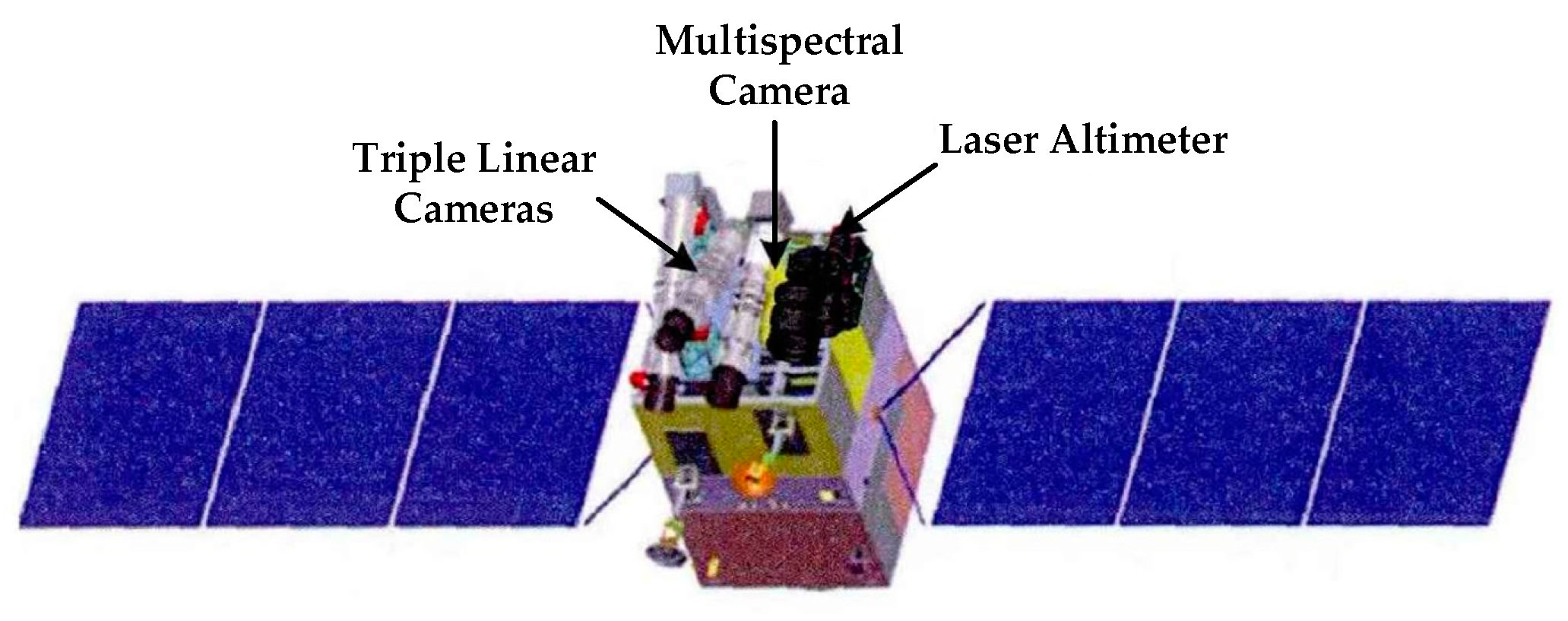
2.1.1. Specifications of ZY3-02
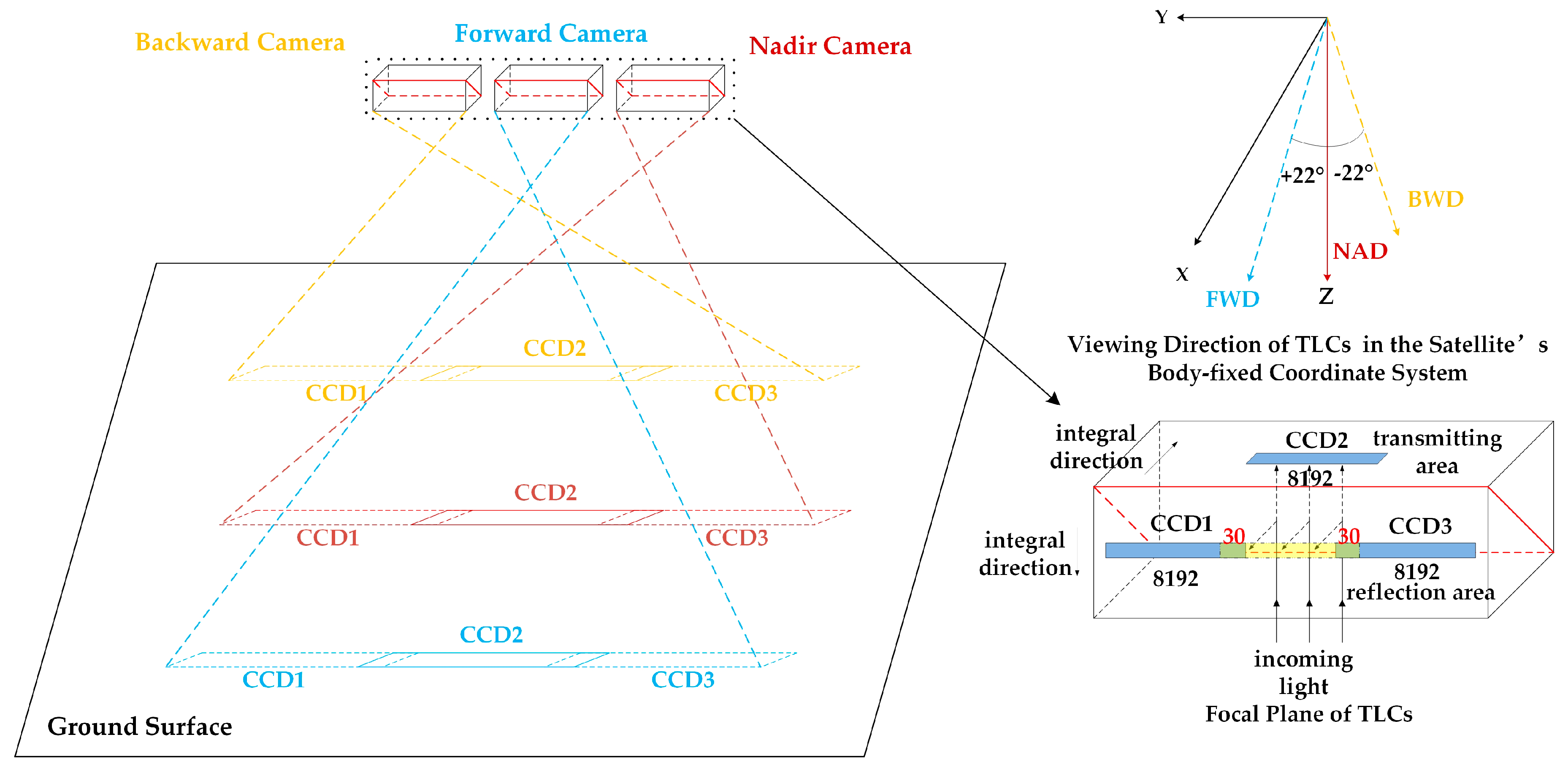
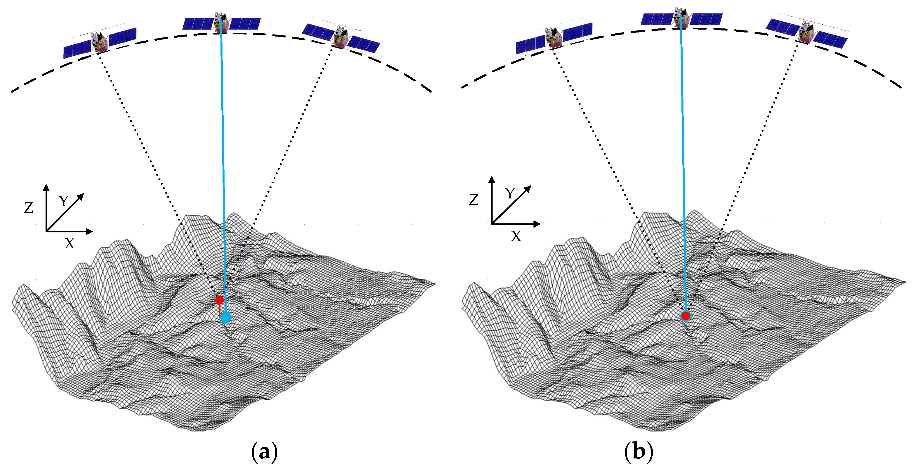
2.1.2. Geometric Model of TLCs
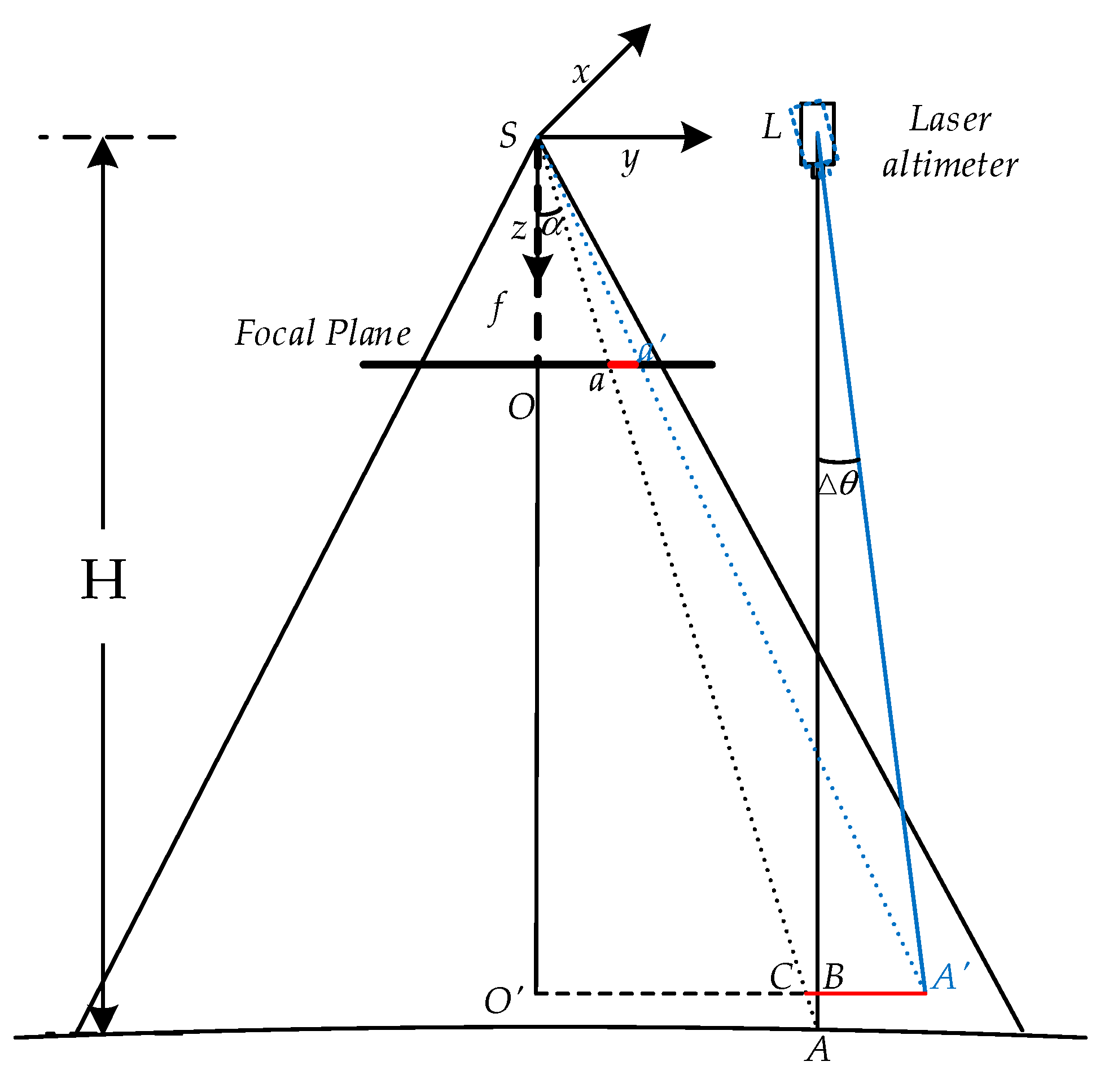
2.1.3. Geometric Model for the Laser Altimeter
2.2. Integration of Stereo Images and Laser Altimeter Data for ZY3-02 Satellite
2.2.1. Overview of the Approach
- (1)
- Based on the initial orientation parameters, the geometric models of stereo images and laser altimeter data are built respectively;
- (2)
- Obtain the tie points of stereo images by image registration and their ground coordinates through space intersection;
- (3)
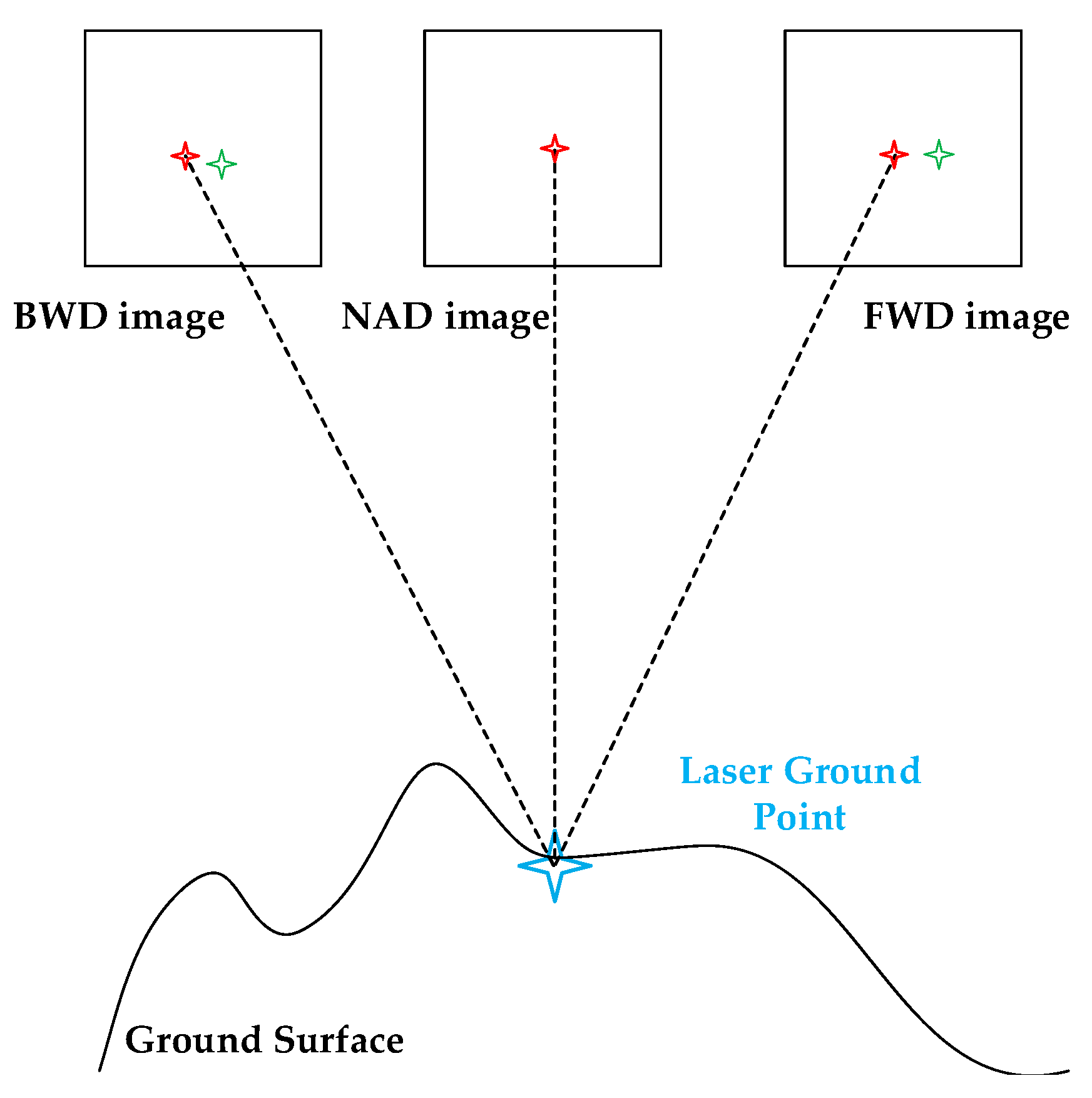
- Calculate the ground coordinates of LAPs and obtain the corresponding image coordinates in stereo images by back-projection; by using the laser points projected on the NAD camera image as references, obtain the LAPs on the BWD and FWD camera images by registration; the discrepancies between these two image coordinates are defined as the constraint in the combined adjustment;
- (4)
- Establish the observation equations for the combined adjustment model with the constraint in image space and solve the adjustment parameters;
- (5)
- Iterate steps (2)–(4) until the residuals of the adjustment parameters meet the threshold;
- (6)
- Generate the improved topographical model with the refined image orientation parameters and laser ground points.
2.2.2. Constraints in the Combined Adjustment Model
2.2.3. Combined Adjustment Model
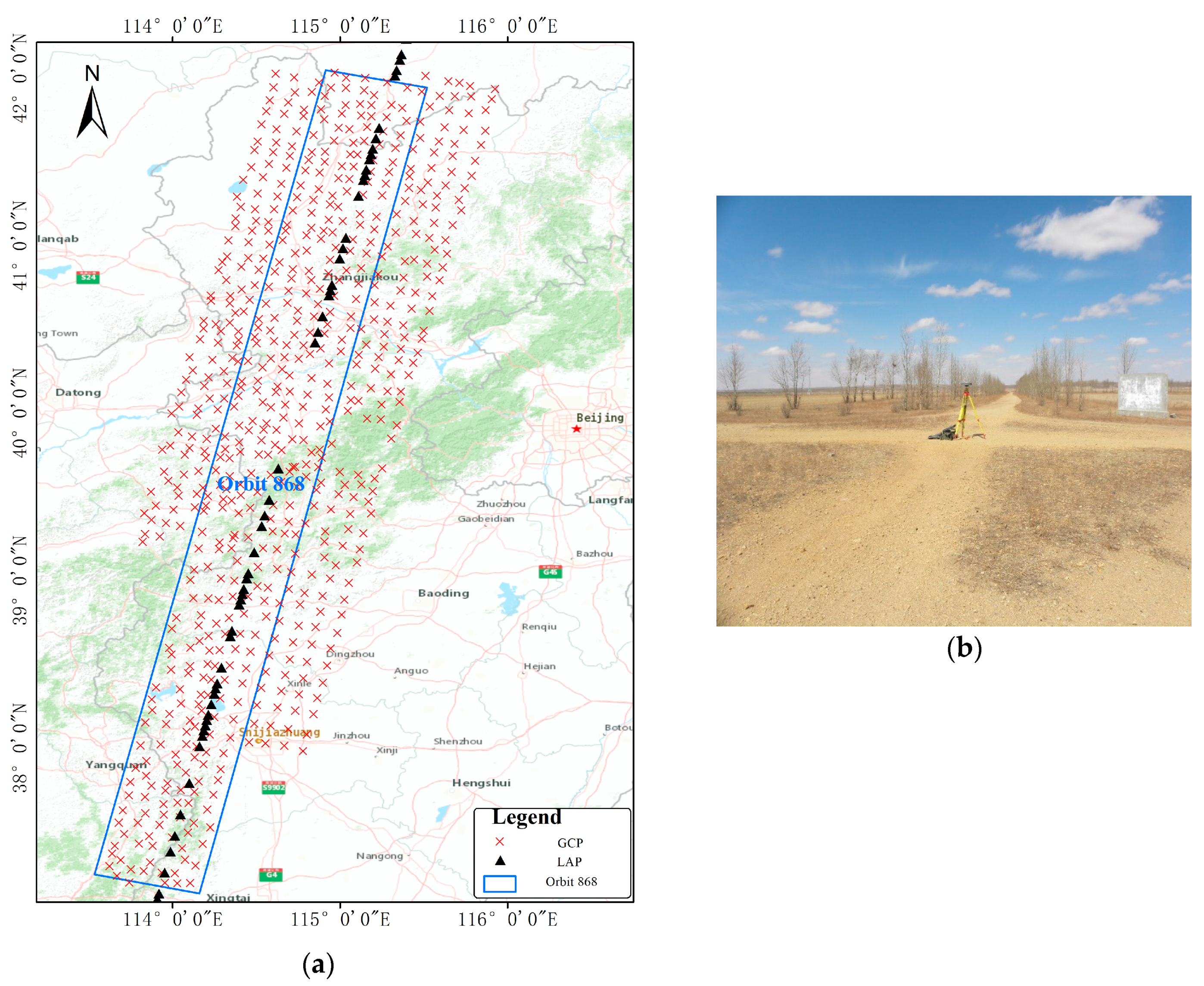
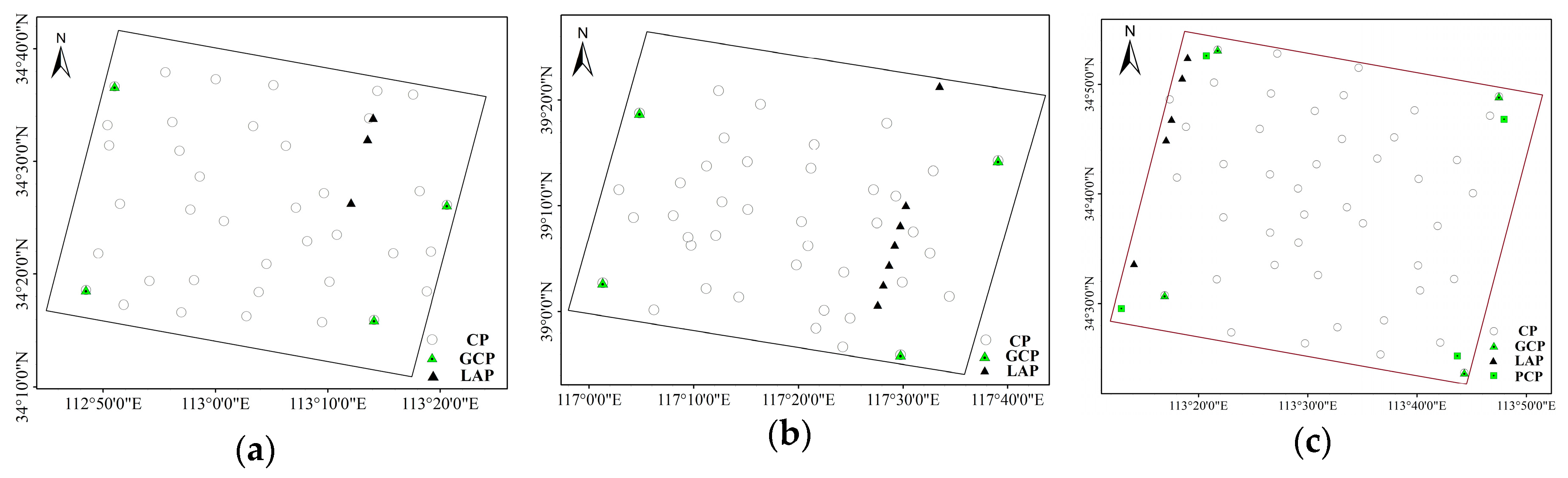
2.3. Introduction to the Experimental Area and Data Sources
- 1.
- Calculate the ground coordinates in the geocentric Cartesian coordinate system for laser footprint based on the geometric model of laser altimeter, and convert the coordinates in the geocentric Cartesian coordinate system to the coordinates in the geographical coordinate system;
- 2.
- Second, extract the elevation value that can be directly interpolated in SRTM data according to the plane coordinates of the laser footprint. It is noted that the should be converted to the same height Datum with the elevation ;
- 3.
- Compare elevation of the laser footprint with the elevation value of SRTM to calculate the , and eliminate the laser points satisfying the condition , is the absolute elevation accuracy of SRTM data.
3. Results
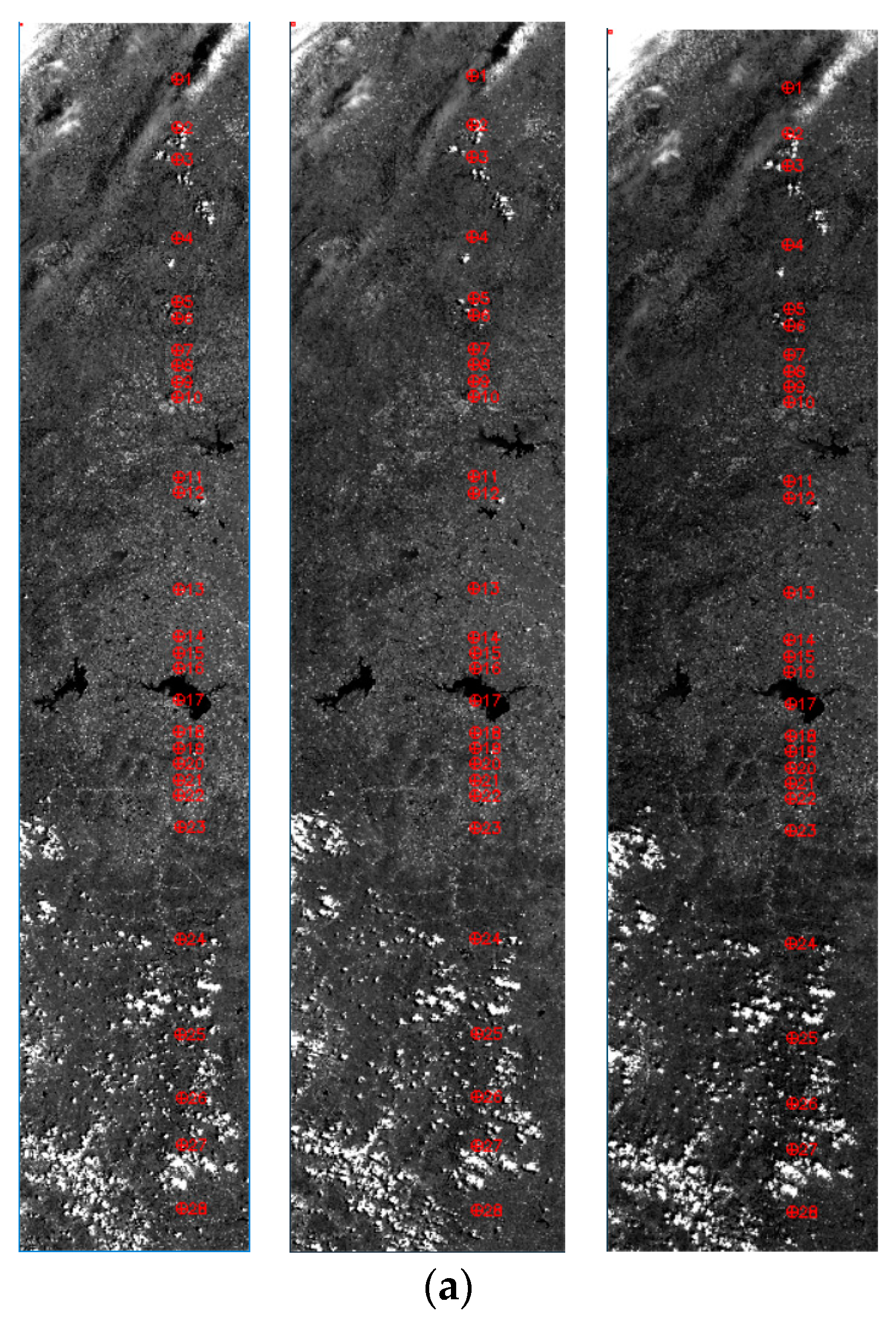
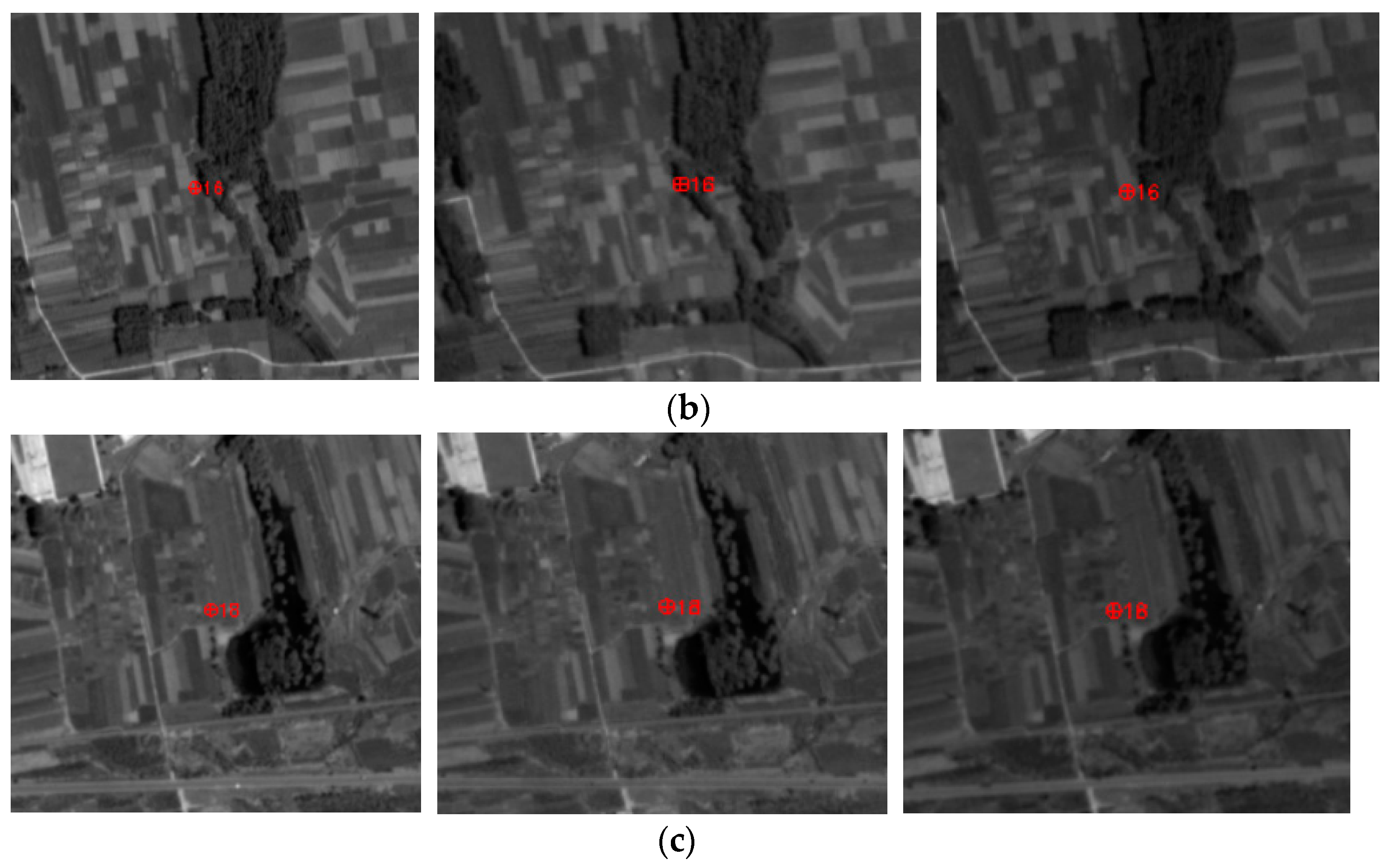
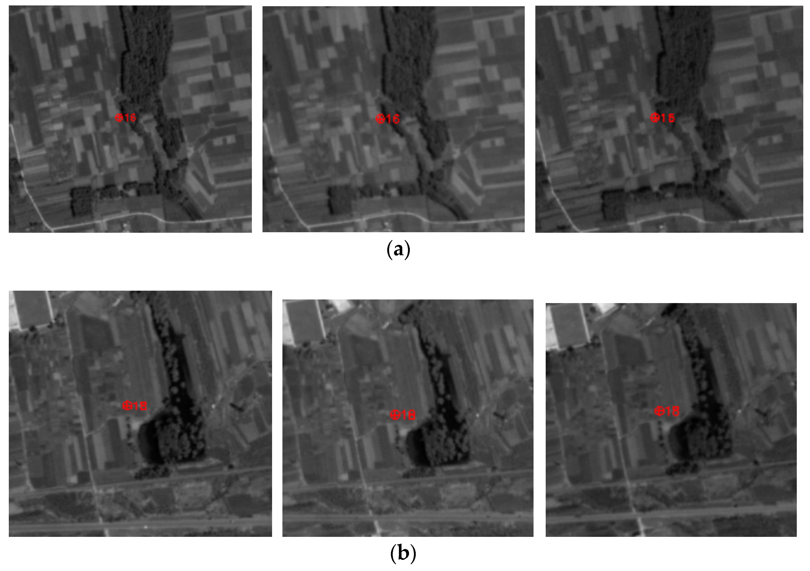
3.1. Inconsistency between ZY3-02 Stereo Camera Images and Laser Ranging Data
3.2. Validation of the Proposed Combined Adjustment Model
3.2.1. Validation Using the Standard Scene
- 1.
- Plan 1: the free-net block adjustment without GCPs;
- 2.
- Plan 2: block adjustment with four GCPs distributed at four corners of the research area;
- 3.
- Plan 3: proposed combined adjustment using one LAP located in the middle of the research area;
- 4.
- Plan 4: proposed combined adjustment using two LAPs located in the middle and start or end of the research area;
- 5.
- Plan 5: proposed combined adjustment using all of the available LAPs in the research area.
- 6.
- Plan 6: proposed combined adjustment using the additional PCPs in the research area;
- 7.
- Plan 7: proposed combined adjustment using all of the available LAPs and the additional PCPs simultaneously in the research area.
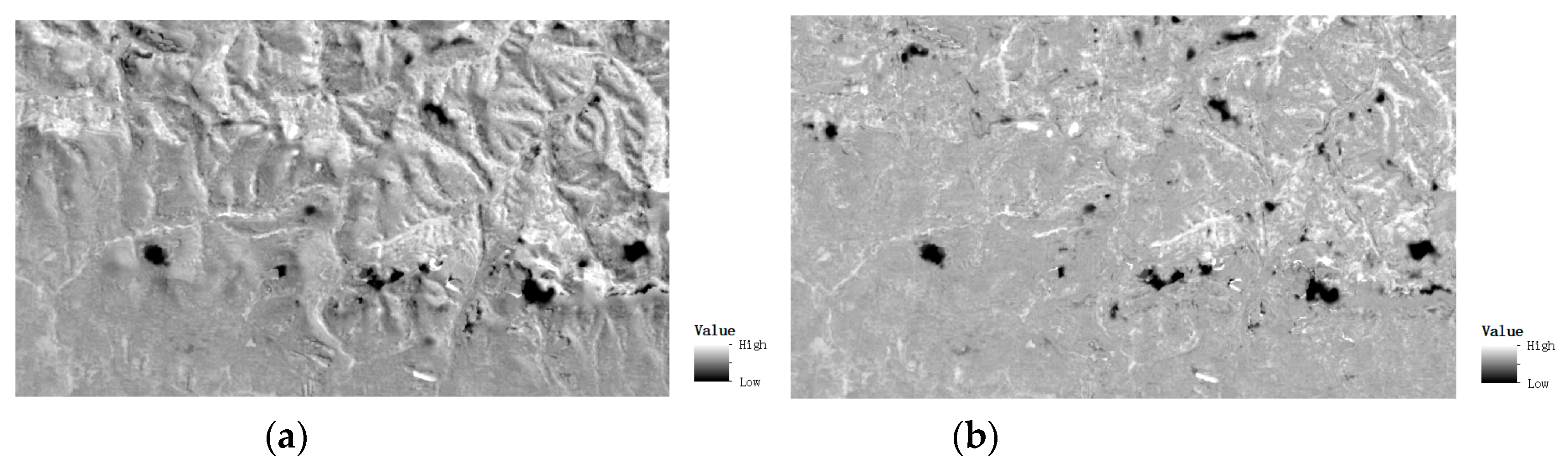
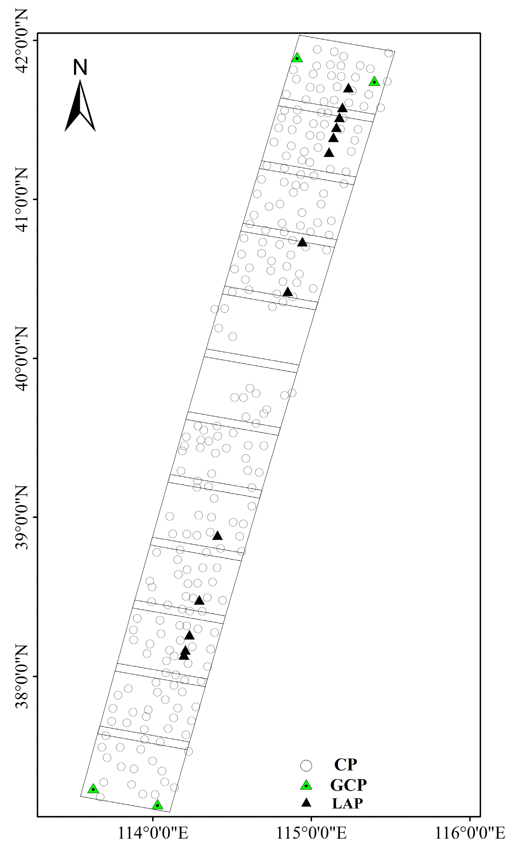
3.2.2. Validation at the TaiHang Area
4. Discussion
5. Conclusions
- (1)
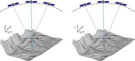
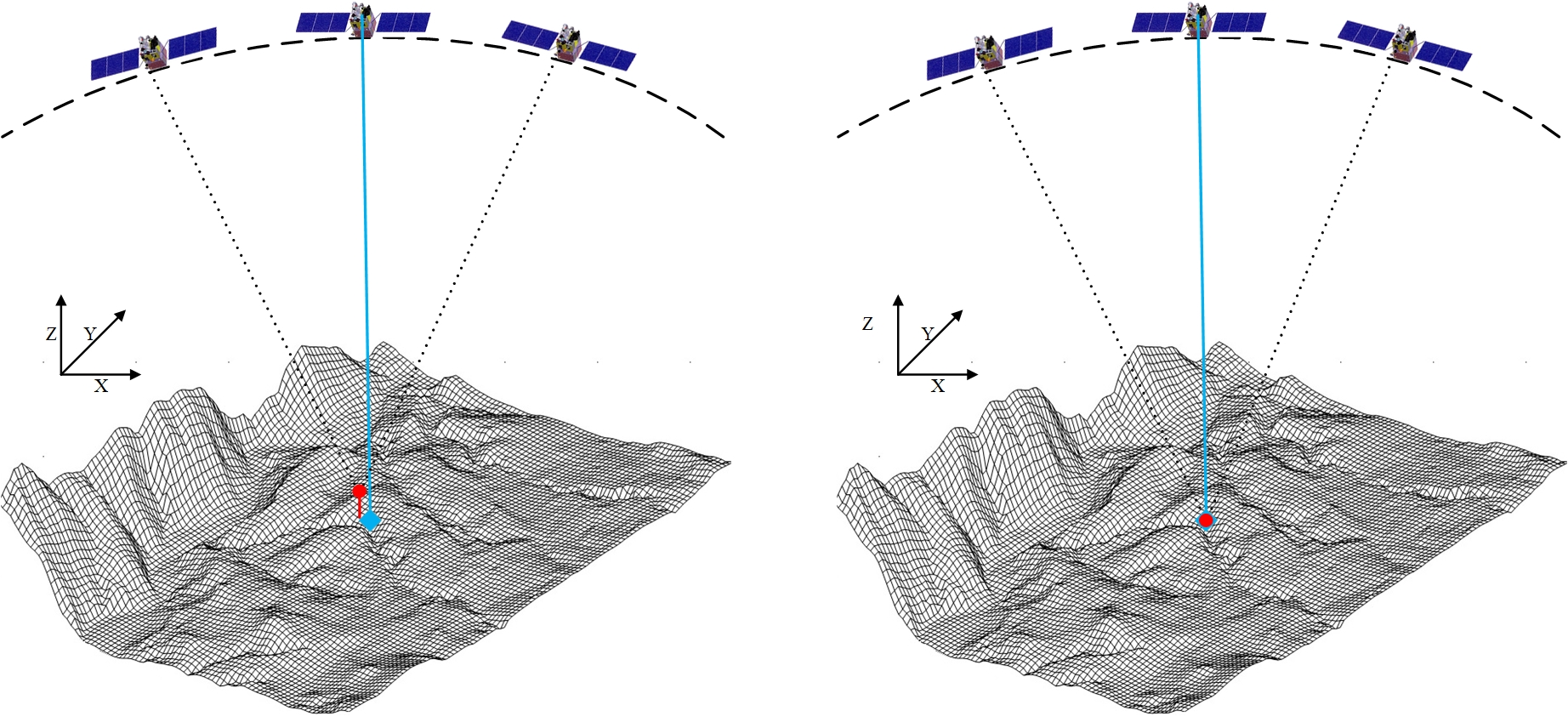
- Inconsistencies exist between the stereo images and laser altimeter data for the ZY3-02 satellite. For the same LAP overlaid on the NAD, BWD, and FWD images, the image points on three-view images are not the homologous points, and this is mainly caused by the errors of orientation parameters. The proposed combined adjustment utilizes the laser range with high accuracy for correcting the orientation parameters and eliminating these inconsistencies.
- (2)
- After applying the proposed combined adjustment, a superior elevation accuracy can be achieved. Experiments demonstrated that the height accuracy can be improved significantly to the extent of that obtained from block adjustment with four GCPs. Validation work further proved that the improved height accuracy is insensitive to the number of LAPs and locations of LAPs in relation to stereo images. It is suggested that all of the available LAPs in the research area should be involved in the processing of the combined adjustment to obtain results with high reliability.
- (3)
- By introducing the additional PCPs engaged in the combined adjustment, the planimetric accuracy can be improved along with the elevation accuracy. In the Dengfeng area experiment, the adjustment results derived by using LAPs and additional four LAPs were slightly lower than the results from the block adjustment with four GCPs.
Author Contributions
Funding
Acknowledgments
Conflicts of Interest
References
- Tang, X.M.; Xie, J.F.; Wang, X.; Jiang, W.S. High-Precision Attitude Post-Processing and Initial Verification for the ZY-3 Satellite. Remote Sens. 2015, 7, 111–134. [Google Scholar] [CrossRef]
- Kubik, P.; Latry, C.; Lebegue, L. PLEIADES-HR 1A&1B image quality commissioning: Innovative radiometric calibration methods and results. In Proceedings of the SPIE 8866, Earth Observing Systems XVIII, San Diego, CA, USA, 23 September 2013; pp. 886610–886611. [Google Scholar]
- Bouillon, A.; Breton, E.; Lussy, F.D.; Gachet, R. SPOT5 geometric image quality. In Proceedings of the 2003 IEEE International Geoscience and Remote Sensing Symposium, IGARSS ′03, Toulouse, France, 21–25 July 2003; pp. 303–305. [Google Scholar]
- Abshire, J.B.; Sun, X.L.; Riris, H.; Sirota, M.; McGarry, J.; Palm, S.; Ketchum, E.A.; Follas, R.B. Geoscience laser altimeter system (GLAS) on the ICESat mission: Pre-launch and on-orbit measurement performance. In Proceedings of the IGARSS 2003, 2003 IEEE International Geoscience and Remote Sensing Symposium (IEEE Cat. No.03CH37477), Toulouse, France, 21–25 July 2003; pp. 1534–1536. [Google Scholar]
- Schutz, B.E.; Zwally, H.J.; Shuman, C.A.; Hancock, D.; DiMarzio, J.P. Overview of the ICESat Mission. Geophys. Res. Lett. 2005, 32. [Google Scholar] [CrossRef]
- Abshire, J.B.; Sun, X.L.; Afzal, R.S. Mars Orbiter Laser Altimeter: Receiver model and performance analysis. Appl. Opt. 2000, 39, 2449–2460. [Google Scholar] [CrossRef] [PubMed]
- Shan, J.; Yoon, J.S.; Lee, D.S.; Kirk, R.L.; Neumann, G.A.; Acton, C.H. Photogrammetric Analysis of the Mars Global Surveyor Mapping Data. Photogramm. Eng. Remote Sens. 2005, 71, 97–108. [Google Scholar] [CrossRef]
- Cheng, A.F.; Cole, T.D.; Zuber, M.T.; Smith, D.E.; Guo, Y.P.; Davidson, F. In-Flight Calibration of the Near Earth Asteroid Rendezvous Laser Rangefinder. Icarus 2000, 148, 572–586. [Google Scholar] [CrossRef]
- Buratti, B.J.; Hillier, J.K.; Wang, M. The Lunar Opposition Surge: Observations by Clementine. Icarus 1996, 124, 490–499. [Google Scholar] [CrossRef]
- Ouyang, Z.Y.; Jiang, J.S.; LI, C.L.; Sun, H.X.; Zou, Y.L.; Liu, J.Z.; Liu, J.J.; Zhao, B.C.; Ren, X.; Yang, J.F.; et al. Preliminary Scientific Results of Chang’E-1 Lunar Orbiter: Based on Payloads Detection Data in the First Phase. Chin. J. Space Sci. 2008, 28, 361–379. [Google Scholar] [CrossRef]
- Ping, J.S.; Huang, Q.; Yan, J.G.; Cao, J.F.; Tang, G.S.; Shu, R. Lunar topographic model CLTM-s01 from Chang’E-1 laser altimeter. Sci. China Ser. G Phys. Mech. Astron. 2009, 52, 1105–1114. [Google Scholar] [CrossRef]
- Li, R.X.; Niu, X.T.; Liu, C.; Wu, B.; Deshpande, S. Impact of Imaging Geometry on 3D Geopositioning Accuracy of Stereo Ikonos Imagery. Photogramm. Eng. Remote Sens. 2009, 75, 1119–1125. [Google Scholar] [CrossRef]
- Anderson, S.F.; Parker, T.J. Characterization of MER Landing Sites Using MOC and MOLA. In Proceedings of the 33rd Lunar and Planetary Science Conference, League City, TX, USA, 11–15 March 2002; pp. 11–15. [Google Scholar]
- Yoon, J.S.; Shan, J. Combined Adjustment of MOC Stereo Imagery and MOLA Altimetry Data. Photogramm. Eng. Remote Sens. 2005, 71, 1179–1186. [Google Scholar] [CrossRef]
- Spiegel, M. Improvement of interior and exterior orientation of the three line camera HRSC with a simultaneous adjustment. In Proceedings of the ISPRS Technical Commission III Symposium, Photogrammetric Image Analysis, Munich, Germany, 19–21 September 2007. [Google Scholar]
- Spiegel, M.; Schmidt, R.; Stilla, U.; Neukum, G. Improvement of Exterior Orientation of Mars Express HRSC Imagery Using a Photogrammetric Block. In Proceedings of the 38th Lunar and Planetary Science Conference, Lunar and Planetary Science XXXVIII, League City, TX, USA, 12–16 March 2007; p. 1608. [Google Scholar]
- Rosiek, M.R.; Kirk, R.L.; Howington-Kraus, E. Combining Lunar Photogrammetric Topographic Data with Clementine LIDAR Data. In Proceedings of the ISPRS WG IV/9: Extraterrestrial Mapping Workshop “Planetary Mapping 2001”, Flagstaff, AZ, USA, 14–15 October 2001. [Google Scholar]
- Di, K.C.; Yue, Z.Y.; Peng, M.; Liu, Z.Q. Co-registration of chang’e-1 stereo images and laser altimeter data for 3d mapping of lunar surface. In Proceedings of the Symposium of ISPRS Technical Commission IV & AutoCartoin Conjunction with ASPRS/CaGIS 2010 Fall Specialty Conference, Orlando, FL, USA, 15–19 November 2010; Volume 38. [Google Scholar]
- Besl, P.J.; McKay, N.D. A method for registration of 3-D shapes. IEEE Trans. Pattern Anal. Mach. Intell. 1992, 14, 239–256. [Google Scholar] [CrossRef]
- Di, K.C.; Hu, W.M.; Liu, Y.L.; Peng, M. Co-registration of Chang’E-1 stereo images and laser altimeter data with crossover adjustment and image sensor model refinement. Adv. Space Res. 2012, 50, 1615–1628. [Google Scholar] [CrossRef]
- Wu, B.; Guo, J.; Zhang, G.; King, B.A.; Li, Z.; Chen, L. Integration of Chang’E-1 Imagery and Laser Altimeter Data for Precision Lunar Topographic Modeling. IEEE Trans. Geosci. Remote Sens. 2011, 49, 4889–4903. [Google Scholar] [CrossRef]
- Zwally, H.J.; Schutz, B.; Abdalati, W.; Abshire, J.; Bentley, C.; Brenner, A.; Bufton, J.; Dezio, J.; Hancock, D.; Harding, D.; et al. ICESat’s laser measurements of polar ice, atmosphere, ocean, and land. J. Geodyn. 2002, 34, 405–445. [Google Scholar] [CrossRef]
- Teo, T.; Chen, L.; Liu, C.; Tung, Y.; Wu, W. DEM-Aided Block Adjustment for Satellite Images with Weak Convergence Geometry. IEEE Trans. Geosci. Remote Sens. 2010, 48, 1907–1918. [Google Scholar] [CrossRef]
- Yamanokuchi, T.; Doi, K.; Shibuya, K. Combined use of InSAR and ICESat/GLAS data for high accuracy DEM generation on antarctica. In Proceedings of the 2007 IEEE International Geoscience and Remote Sensing Symposium, Barcelona, Spain, 23–28 July 2007; pp. 1229–1231. [Google Scholar]
- Tang, X.M.; Xie, J.F.; Fu, X.K.; Mo, F.; Li, S.N.; Dou, X.H. ZY3-02 Laser Altimeter On-orbit Geometrical Calibration and Test. Acta Geod. Cartogr. Sin. 2017, 46, 714–723. [Google Scholar] [CrossRef]
- Xie, J.F.; Tang, X.M.; Mo, F.; Tang, H.Z.; Wang, Z.M.; Wang, X.; Liu, Y.X.; Tian, S.Q.; Liu, R.; Xia, X.F. In-orbit geometric calibration and experimental verification of the ZY3-02 laser altimeter. Photogramm. Rec. 2018, 33, 341–362. [Google Scholar] [CrossRef]
- Li, G.Y.; Tang, X.M.; Gao, X.M.; Wang, X.; Fan, W.F.; Chen, J.Y.; Mo, F. Integration of ZY3-02 Satellite Laser Altimetry Data and Stereo Images for High-Accuracy Mapping. Photogramm. Eng. Remote Sens. 2018, 84, 569–578. [Google Scholar] [CrossRef]
- Li, D.R. China’s First Civilian Three-line-array Stereo Mapping Satellite: ZY-3. Acta Geod. Cartogr. Sin. 2012, 41, 317–322. [Google Scholar]
- Xu, K.; Jiang, Y.H.; Zhang, G.; Zhang, Q.J.; Wang, X. Geometric Potential Assessment for ZY3-02 Triple Linear Array Imagery. Remote Sens. 2017, 9, 658. [Google Scholar] [CrossRef]
- Zhang, G.; Li, S.; Huang, W.; Li, D. Geometric Calibration and Validation of ZY3-02 Satellite Laser Altimeter System. Geomat. Inf. Sci. Wuhan Univ. 2017, 42, 1589–1596. [Google Scholar] [CrossRef]
- Tang, X.M.; Zhang, G.; Zhu, X.Y.; Pan, H.B.; Jiang, Y.H.; Zhou, P. Triple linear-array image geometry model of ZiYuan-3 surveying satellite and its validation. Int. J. Image Data Fusion 2012, 4, 33–51. [Google Scholar] [CrossRef]
- Poli, D.; Toutin, T. Review of developments in geometric modelling for high resolution satellite pushbroom sensors. Photogramm. Rec. 2012, 27, 58–73. [Google Scholar] [CrossRef]
- Wu, Q.B.; Zhao, C.M.; Zhu, G.B.; Wei, Z.B. Rapid Precision Orbit Determination Based on Dual-Frequency GPS Receiver for ZY3-02 Satellite. J. Geod. Geodyn. 2018, 38, 73–77. [Google Scholar] [CrossRef]
- Zhang, G.; Jiang, Y.H.; Li, D.R.; Huang, W.C.; Pan, H.B.; Tang, X.M.; Zhu, X.Y. In-Orbit Geometric Calibration and Validation Of ZY-3 Linear Array Sensors. Photogramm. Rec. 2014, 29, 68–88. [Google Scholar] [CrossRef]
- Takaku, J.; Tadono, T. PRISM On-Orbit Geometric Calibration and DSM Performance. IEEE Trans. Geosci. Remote Sens. 2009, 47, 4060–4073. [Google Scholar] [CrossRef]
- Tang, X.M.; Xie, J.F.; Gao, X.M.; Mo, F.; Feng, W.; Liu, R. The In-Orbit Calibration Method Based on Terrain Matching with Pyramid-Search for the Spaceborne Laser Altimeter. IEEE J. Sel. Top. Appl. Earth Obs. Remote Sens. 2019, 12, 1053–1062. [Google Scholar] [CrossRef]
- Deng, M.J.; Zhang, G.; Zhao, R.S.; Zhang, Q.J.; Li, D.R.; Li, J.S. Assessment of the geolocation accuracy of YG-13A high-resolution SAR data. Remote Sens. Lett. 2018, 9, 101–110. [Google Scholar] [CrossRef]
- Dial, G.; Grodecki, J. Test ranges for metric calibration and validation of high-resolution satellite imaging systems. In Proceedings of the International Workshop on Radiometric and Geometric Calibration, Gulfport, MI, USA, 2–5 December 2003. [Google Scholar]
- Hirschmuller, H. Stereo Processing by Semiglobal Matching and Mutual Information. IEEE Trans. Pattern Anal. Mach. Intell. 2008, 30, 328–341. [Google Scholar] [CrossRef]


| Parameters | Designed Value |
|---|---|
| Laser pulse width | 7 ns |
| Repetitive frequency | 2 Hz |
| power consumption | 45 W |
| Weight | 40 kg |
| Single pulse energy | 200 mJ |
| Effective distance | 480~520 km |
| Laser footprint size | >75 m |
| center wavelength | 1064 nm |
| Instantaneous emission field of view | 0.1 mrad |
| Instantaneous receiving field of view | 0.5 mrad |
| Detection probability | ≥95% (flat area @ 500 km) |
| False alarm probability | ≤5 × 10⁻⁴ (flat area @ 500 km) |
| Ranging accuracy | 1 m (3σ, slope < 2°) |
| Area | Stereo Images | Laser Altimeter Data | |||
|---|---|---|---|---|---|
| Acquisition Date | Elevation Range (m) | Acquisition Date | Track ID | * Location | |
| Songshan | 26 July 2016 | (123, 1491) | 31 July 2016 | Orbit 944 | Center-right |
| Taihang | 26 July 2016 | (75, 2750) | Center-right | ||
| Dengfeng | 3 October 2016 | (−1, 778) | Left | ||
| Tianjin | 30 August 2016 | (−7, 0) | 4 September 2016 | Orbit 1476 | Center-right |
| Area. | * GSD of DOM (m) | Planimetric Accuracy of the DOM RMS (m) | Height Accuracy of the DEM RMS (m) | Center Latitude and Longitude |
|---|---|---|---|---|
| Tianjin | 0.5 | 1 | 1.5 | 38.00° N, 112.52° E |
| Songshan | 0.5 | 1 | 1.5 | 34.65° N, 113.55° E |
| Dengfeng | 0.2 | 0.4 | 0.7 | 34.45° N, 113.07° E |
| Area | Plan | No. of LAPs/PPCs | No. of GCPs/CPs | RMSE of CPs (m) | * CE90 (m) | * LE90 (m) | ||
|---|---|---|---|---|---|---|---|---|
| East | North | Height | ||||||
| Songshan | P1 | 0/0 | 0/40 | 13.84 | 1.96 | 13.93 | 15.80 | 16.73 |
| P2 | 0/0 | 4/36 | 1.61 | 1.46 | 2.37 | 3.36 | 3.95 | |
| P3 | 1/0 | 0/40 | 13.30 | 2.02 | 2.33 | 15.03 | 3.79 | |
| P4 | 2/0 | 0/44 | 13.31 | 2.05 | 2.35 | 15.31 | 3.76 | |
| P5 | 3/0 | 0/26 | 13.30 | 2.02 | 2.34 | 15.31 | 3.77 | |
| Tianjin | P1 | 0/0 | 0/40 | 26.35 | 7.84 | 18.51 | 28.90 | 20.51 |
| P2 | 0/0 | 4/36 | 1.42 | 1.24 | 1.86 | 2.91 | 1.64 | |
| P3 | 1/0 | 0/4 | 25.38 | 7.99 | 1.59 | 28.00 | 2.49 | |
| P4 | 2/0 | 0/40 | 25.34 | 8.00 | 2.03 | 27.97 | 1.81 | |
| P5 | 7/0 | 0/40 | 25.43 | 7.98 | 1.72 | 28.05 | 2.29 | |
| Dengfeng | P1 | 0/0 | 0/45 | 16.91 | 12.01 | 20.99 | 21.89 | 23.01 |
| P2 | 0/0 | 4/41 | 1.57 | 0.98 | 1.58 | `2.78 | 2.01 | |
| P3 | 1/0 | 0/45 | 16.93 | 12.04 | 1.60 | 21.91 | 2.65 | |
| P4 | 2/0 | 0/45 | 16.93 | 12.05 | 1.66 | 21.91 | 2.55 | |
| P5 | 5/0 | 0/45 | 16.93 | 12.04 | 1.63 | 21.92 | 2.60 | |
| P6 | 0/4 | 0/45 | 1.97 | 1.48 | 14.45 | 3.47 | 16.42 | |
| P7 | 5/4 | 0/45 | 2.01 | 1.42 | 1.61 | 3.45 | 2.63 | |
| Area | Terrain | Plan | Minimum (m) | Maximum (m) | MEAN (m) | RMSE (m) |
|---|---|---|---|---|---|---|
| Dengfeng area1 | Mountainous | P6 | −24.29 | 61.70 | 22.94 | 5.58 |
| P7 | −54.30 | 40.22 | 3.61 | 4.42 | ||
| Dengfeng area2 | Hilly | P6 | −8.48 | 61.20 | 24.64 | 4.98 |
| P7 | −23.23 | 30.12 | 1.02 | 4.53 | ||
| Dengfeng area3 | Plain | P6 | −0.32 | 51.80 | 22.96 | 3.53 |
| P7 | −23.55 | 26.44 | 1.76 | 2.98 |
| Area | Plan | No. of LAPs | No. of PCPs | No. of GCPs/CPs | RMSE of CPs (m) | CE90 (m) | LE90 (m) | ||
|---|---|---|---|---|---|---|---|---|---|
| East | North | Height | |||||||
| Taihang | P1 | 0 | 0 | 0/245 | 12.28 | 2.21 | 8.29 | 14.69 | 10.51 |
| P2 | 0 | 0 | 4/241 | 1.83 | 2.00 | 2.48 | 4.13 | 2.15 | |
| P3 | 1 | 0 | 0/245 | 12.02 | 2.55 | 2.79 | 14.43 | 2.79 | |
| P4 | 2 | 0 | 0/245 | 12.01 | 2.55 | 2.57 | 14.41 | 3.04 | |
| P5 | 13 | 0 | 0/245 | 11.98 | 2.55 | 2.01 | 14.39 | 2.87 | |
© 2019 by the authors. Licensee MDPI, Basel, Switzerland. This article is an open access article distributed under the terms and conditions of the Creative Commons Attribution (CC BY) license (http://creativecommons.org/licenses/by/4.0/).
Share and Cite
Zhang, G.; Xu, K.; Jia, P.; Hao, X.; Li, D. Integrating Stereo Images and Laser Altimeter Data of the ZY3-02 Satellite for Improved Earth Topographic Modeling. Remote Sens. 2019, 11, 2453. https://doi.org/10.3390/rs11202453
Zhang G, Xu K, Jia P, Hao X, Li D. Integrating Stereo Images and Laser Altimeter Data of the ZY3-02 Satellite for Improved Earth Topographic Modeling. Remote Sensing. 2019; 11(20):2453. https://doi.org/10.3390/rs11202453
Chicago/Turabian StyleZhang, Guo, Kai Xu, Peng Jia, Xiaoyun Hao, and Deren Li. 2019. "Integrating Stereo Images and Laser Altimeter Data of the ZY3-02 Satellite for Improved Earth Topographic Modeling" Remote Sensing 11, no. 20: 2453. https://doi.org/10.3390/rs11202453
APA StyleZhang, G., Xu, K., Jia, P., Hao, X., & Li, D. (2019). Integrating Stereo Images and Laser Altimeter Data of the ZY3-02 Satellite for Improved Earth Topographic Modeling. Remote Sensing, 11(20), 2453. https://doi.org/10.3390/rs11202453